WO2019116545A1 - スクリーン印刷機 - Google Patents
スクリーン印刷機 Download PDFInfo
- Publication number
- WO2019116545A1 WO2019116545A1 PCT/JP2017/045136 JP2017045136W WO2019116545A1 WO 2019116545 A1 WO2019116545 A1 WO 2019116545A1 JP 2017045136 W JP2017045136 W JP 2017045136W WO 2019116545 A1 WO2019116545 A1 WO 2019116545A1
- Authority
- WO
- WIPO (PCT)
- Prior art keywords
- mask
- tension
- substrate
- measuring device
- screen printing
- Prior art date
- Legal status (The legal status is an assumption and is not a legal conclusion. Google has not performed a legal analysis and makes no representation as to the accuracy of the status listed.)
- Ceased
Links
Images



Classifications
-
- B—PERFORMING OPERATIONS; TRANSPORTING
- B41—PRINTING; LINING MACHINES; TYPEWRITERS; STAMPS
- B41F—PRINTING MACHINES OR PRESSES
- B41F15/00—Screen printers
- B41F15/08—Machines
- B41F15/0881—Machines for printing on polyhedral articles
-
- B—PERFORMING OPERATIONS; TRANSPORTING
- B41—PRINTING; LINING MACHINES; TYPEWRITERS; STAMPS
- B41F—PRINTING MACHINES OR PRESSES
- B41F15/00—Screen printers
- B41F15/14—Details
- B41F15/34—Screens, Frames; Holders therefor
- B41F15/36—Screens, Frames; Holders therefor flat
-
- B—PERFORMING OPERATIONS; TRANSPORTING
- B23—MACHINE TOOLS; METAL-WORKING NOT OTHERWISE PROVIDED FOR
- B23K—SOLDERING OR UNSOLDERING; WELDING; CLADDING OR PLATING BY SOLDERING OR WELDING; CUTTING BY APPLYING HEAT LOCALLY, e.g. FLAME CUTTING; WORKING BY LASER BEAM
- B23K3/00—Tools, devices or special appurtenances for soldering, e.g. brazing, or unsoldering, not specially adapted for particular methods
- B23K3/06—Solder feeding devices; Solder melting pans
- B23K3/0607—Solder feeding devices
- B23K3/0638—Solder feeding devices for viscous material feeding, e.g. solder paste feeding
-
- B—PERFORMING OPERATIONS; TRANSPORTING
- B41—PRINTING; LINING MACHINES; TYPEWRITERS; STAMPS
- B41F—PRINTING MACHINES OR PRESSES
- B41F15/00—Screen printers
- B41F15/14—Details
- B41F15/44—Squeegees or doctors
-
- H—ELECTRICITY
- H05—ELECTRIC TECHNIQUES NOT OTHERWISE PROVIDED FOR
- H05K—PRINTED CIRCUITS; CASINGS OR CONSTRUCTIONAL DETAILS OF ELECTRIC APPARATUS; MANUFACTURE OF ASSEMBLAGES OF ELECTRICAL COMPONENTS
- H05K3/00—Apparatus or processes for manufacturing printed circuits
- H05K3/30—Assembling printed circuits with electric components, e.g. with resistors
- H05K3/32—Assembling printed circuits with electric components, e.g. with resistors electrically connecting electric components or wires to printed circuits
- H05K3/34—Assembling printed circuits with electric components, e.g. with resistors electrically connecting electric components or wires to printed circuits by soldering
-
- H—ELECTRICITY
- H05—ELECTRIC TECHNIQUES NOT OTHERWISE PROVIDED FOR
- H05K—PRINTED CIRCUITS; CASINGS OR CONSTRUCTIONAL DETAILS OF ELECTRIC APPARATUS; MANUFACTURE OF ASSEMBLAGES OF ELECTRICAL COMPONENTS
- H05K3/00—Apparatus or processes for manufacturing printed circuits
- H05K3/30—Assembling printed circuits with electric components, e.g. with resistors
- H05K3/32—Assembling printed circuits with electric components, e.g. with resistors electrically connecting electric components or wires to printed circuits
- H05K3/34—Assembling printed circuits with electric components, e.g. with resistors electrically connecting electric components or wires to printed circuits by soldering
- H05K3/3452—Solder masks
-
- B—PERFORMING OPERATIONS; TRANSPORTING
- B23—MACHINE TOOLS; METAL-WORKING NOT OTHERWISE PROVIDED FOR
- B23K—SOLDERING OR UNSOLDERING; WELDING; CLADDING OR PLATING BY SOLDERING OR WELDING; CUTTING BY APPLYING HEAT LOCALLY, e.g. FLAME CUTTING; WORKING BY LASER BEAM
- B23K2101/00—Articles made by soldering, welding or cutting
- B23K2101/36—Electric or electronic devices
- B23K2101/42—Printed circuits
-
- B—PERFORMING OPERATIONS; TRANSPORTING
- B41—PRINTING; LINING MACHINES; TYPEWRITERS; STAMPS
- B41P—INDEXING SCHEME RELATING TO PRINTING, LINING MACHINES, TYPEWRITERS, AND TO STAMPS
- B41P2215/00—Screen printing machines
- B41P2215/50—Screen printing machines for particular purposes
-
- H—ELECTRICITY
- H05—ELECTRIC TECHNIQUES NOT OTHERWISE PROVIDED FOR
- H05K—PRINTED CIRCUITS; CASINGS OR CONSTRUCTIONAL DETAILS OF ELECTRIC APPARATUS; MANUFACTURE OF ASSEMBLAGES OF ELECTRICAL COMPONENTS
- H05K2203/00—Indexing scheme relating to apparatus or processes for manufacturing printed circuits covered by H05K3/00
- H05K2203/01—Tools for processing; Objects used during processing
- H05K2203/0104—Tools for processing; Objects used during processing for patterning or coating
- H05K2203/0139—Blade or squeegee, e.g. for screen printing or filling of holes
-
- H—ELECTRICITY
- H05—ELECTRIC TECHNIQUES NOT OTHERWISE PROVIDED FOR
- H05K—PRINTED CIRCUITS; CASINGS OR CONSTRUCTIONAL DETAILS OF ELECTRIC APPARATUS; MANUFACTURE OF ASSEMBLAGES OF ELECTRICAL COMPONENTS
- H05K2203/00—Indexing scheme relating to apparatus or processes for manufacturing printed circuits covered by H05K3/00
- H05K2203/16—Inspection; Monitoring; Aligning
- H05K2203/163—Monitoring a manufacturing process
Definitions
- the present invention relates to a screen printing machine capable of measuring the tension of a mask in the machine.
- a substrate is placed under a mask in which printing pattern holes are formed, and cream solder is spread on the upper surface of the mask. Then, the cream solder is applied to the substrate through the print pattern holes, whereby printing according to the print pattern is performed on the substrate. At this time, if the separation of the printing plate after printing is not appropriate, printing defects such as blurring of the printing pattern occur. As the cause, the tension of the mask used repeatedly may be loosened, and the degree of adhesion between the mask and the substrate may be disturbed.
- Patent Document 1 listed below describes the measurement of mask tension.
- a tension measurement rod provided in the print head is used, and the reaction force generated at this time is measured by the load cell by pressurizing the measurement portion of the mask with a predetermined thrust.
- the tension actual reaction force is measured by the monitoring means by the recognition camera.
- Patent Document 2 discloses a mask tension measuring device for measuring the displacement amount of the mask as an external device of the screen printing machine.
- the tension measuring device is such that a weight for applying a constant load to the mask supported at the left and right ends is placed, and the displacement amount at that time is measured by the gap sensor as the tension of the mask.
- the apparatus configured as an external device of the screen printing machine has disadvantages such as not only being costly, but also the substrate manufacturing line being enlarged. Moreover, how to apply a load to a mask using a weight is inconvenient in its handling and load adjustment.
- this invention aims at providing the screen printer which can measure the tension of a mask in in-machine in order to solve this subject.
- a screen printing machine includes a mask holding device for holding a mask, a substrate device for positioning a substrate from below with respect to the mask held by the mask holding device, and cream solder on the upper surface of the mask
- a squeegee device for spreading, a mask pressing device for pressing the mask with a set pressure by a pusher mounted on an upper traveling device or a lower traveling device for the mask, the upper traveling device or lower side opposite to the pusher It has a mask measuring device which is mounted on a traveling device and measures the height of the mask, and a tension measuring device which calculates the tension of the mask based on the measurement value of the mask measuring device.
- the mask is pressed by the set pressure from the upper side or the lower side of the mask by the pusher of the mask pressing device, and the height of the deflected mask from the side opposite to the pusher Is measured by the mask measuring device, and based on the measured value, a value regarding the tension of the mask is calculated by the tension measuring device.
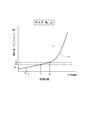
- FIG. 1 is a block diagram schematically showing a control system of a screen printing machine. It is a figure showing the main composition of a mask tension measuring device. It is a figure showing a tension prediction line of a mask. It is the figure which showed the tension line in case the bending of a mask rose sharply contrary to the tension prediction line.
- FIG. 1 is a view simply showing the internal structure of the screen printing machine, which is shown from the machine width direction which is the transport direction of the substrate.
- FIG. 2 is a block diagram simply showing a control system of the screen printing machine.
- the screen printing machine 1 prints cream solder on a substrate, and for example, constitutes a circuit board production line together with a solder inspection machine which inspects a printing state, a component mounting machine which mounts an electronic component on the substrate, etc. It is.
- the substrate is sequentially transported to each machine, and in the screen printing machine 1, the substrate 10 is carried in and out in the machine width direction penetrating the drawing.
- the machine longitudinal direction of the screen printing machine 1 will be described as the Y-axis direction, the machine width direction as the X-axis direction, and the machine height direction as the Z-axis direction.
- the substrate 10 is conveyed under the mask 20 installed in the machine, and the cream solder passes from the upper surface side of the mask 20 through the print pattern holes, and applied to the lower substrate 10 to form a print pattern. Be done. Therefore, the mask 20 is held on the upper side inside the screen printing machine 1 by the pair of mask holders 3 arranged in the machine width direction via the frame 44.
- a squeegee device 4 is installed on the upper side of the mask holder 3 and attached so as to be movable in the longitudinal direction of the machine body.
- a backup device 7 or the like for moving up and down is assembled to the lifting device 8.
- the lifting device 8 includes a lifting platform 12 which slides along a vertical guide rail 11, and the lifting platform 12 is connected to a lifting motor 14 via a ball screw mechanism 13.
- the substrate transfer device 5 and the clamp device 6 are mounted on the elevating table 12 via the support table 15.
- a pair of mask supports 21 are provided on the support base 15 in the longitudinal direction (Y-axis direction) of the machine, and a mask support plate 211 which is in contact with the mask 20 is fixed on the upper surface.
- a ball screw mechanism 22 is formed on the mask support 21 on the right side of the drawing, and adjustment of the distance to the mask support 21 on the left side of the drawing is possible by the mask support motor 24.
- the clamp device 6 has a pair of side frames 25 in the longitudinal direction of the machine orthogonal to the transfer direction of the substrate 10 and is assembled on the support 23.
- a ball screw mechanism 26 is formed on the side frame 25 on the right side of the drawing, and the substrate clamping motor 29 can adjust the distance to the side frame 25 on the left side of the drawing.
- a clamp portion 27 is formed at the upper end portion of the pair of side frames 25 so that the substrate 10 can be gripped by shortening the distance between the clamp portions 27. Then, inside the side frame 25, a substrate transfer device 5 composed of a conveyor belt 28 is assembled.
- a backup device 7 for supporting the substrate 10 is provided between the pair of side frames 25.
- the backup device 7 is configured such that a backup table 31 provided with a plurality of backup pins 32 is supported via a ball screw mechanism and moved up and down by a backup motor 34.
- the support 23 is supported by a ball screw mechanism and configured to be lifted and lowered by a lifting motor 33.
- the support 15 of the clamp device 6 and the backup device 7 can be adjusted in position in the X direction, the Y direction, and the ⁇ direction on the XY plane with respect to the elevator 12.
- a pair of squeegees are mounted on a traveling platform 35 via a lifting device such as a cylinder.
- the carriage 35 is slidably assembled to a guide rod 36 extending in the longitudinal direction of the machine, and is attached via a ball screw mechanism including a screw shaft 37 parallel to the guide rod 36. Therefore, the squeegee device 4 can move linearly in the longitudinal direction of the machine by driving the squeegee motor 38 connected to the screw shaft.
- a camera 41 for picking up an image of a substrate mark, a mask mark and the like is provided between the mask 20 and the clamp device 6.
- the camera 41 is fixed to a Y-axis slide 43 sliding on the Y-axis rail 42, and can move in the longitudinal direction of the machine.
- the X-axis slide 45 is fixed to both ends of the Y-axis rail 42, and the Y-axis rail 42 is bridged to two X-axis rails 46 disposed in the machine width direction via the X-axis slide 45.
- the Y-axis slide 43 is moved by driving a ball screw mechanism (not shown) by the Y-axis motor 47, and the X-axis slide 45 is moved by the linear motor 48. Therefore, the camera 41 can move on the XY plane.
- FIG. 3 is a view showing the main configuration of the mask tension measuring device in the internal structure of the screen printing machine 1. Specifically, an air cylinder 51 as a pusher for pressing the mask 20 downward and a laser displacement gauge 52 as a mask measuring device for measuring the height of the lower surface of the mask 20.
- the air cylinder 51 is mounted on the carriage 35 on the mask, and the laser displacement gauge 52 is mounted on the Y-axis slide 43 below the mask.
- the air cylinder 51 has a pressing member made of resin at the end of the piston rod 511, and the piston rod 511 is attached so as to be extended and contracted in the vertical direction.
- the air cylinder 51 is a single-acting cylinder which is biased by a spring in a direction to contract and which is extended by air pressure applied to the piston from the head side. Therefore, an air pipe 53 is connected to the air cylinder 51 so that air from a compressor (not shown) is supplied to the head side, and the air pipe 53 is provided with a regulator 55 and a three-way solenoid valve 56.
- the control device 9 is connected to the regulator 55 and the three-way solenoid valve 56, and drive control of each is performed. Therefore, in the mask tension measuring device, the air of the set pressure is supplied to the air cylinder 51 by the control of the regulator 55, and the air is supplied to the air cylinder 51 by the control of the three-way solenoid valve 56. It is possible to switch between air release to the atmosphere.
- the laser displacement meter 52 is also connected to the control device 9, and measurement data of the height of the mask 20 is transmitted to the control device 9.
- the screen printing machine 1 is equipped with a control device 9 that controls the overall drive.
- a microprocessor (CPU) 61 centrally controls the entire control device
- the ROM 62 stores system programs executed by the CPU 61, control parameters and the like
- the RAM 63 stores temporary calculation data, display data and the like.
- a touch panel type operation display device 67 is attached to the front surface portion of the screen printing machine 1 so that data input by the operator and display of work contents and numerical values can be performed.
- the operation display device 67 is connected to the control device 9 through the I / O port 65.
- Various other motors are connected to the I / O port 65 through drivers.
- Servomotors are used for the various motors illustrated, and information (signals) on the amount of rotation of the servomotor can be transmitted to the control device 9 from an encoder incorporated therein.
- a laser displacement meter 52, a regulator 55 and a three-way solenoid valve 56 are connected to the I / O port 65, and a mask tension measuring device in the screen printing machine 1 is configured.
- the non-volatile memory 64 of the control device 9 stores information necessary for the process performed by the CPU 61, stores a print control program of the screen printer 1 described below, and executes the print process on the substrate 10 by execution thereof. It is supposed to be. Further, in the present embodiment, a tension measurement program for controlling the mask tension measurement apparatus, a usage prediction calculation program for calculating the appropriate usage prediction number of the mask 20, and the like are also stored.
- the operation of the screen printing machine 1 will be described.
- the substrate 10 is transported between the side frames 25 and lifted by the backup pins 32, the substrate 10 is sandwiched and held by the pair of clamp portions 27.
- the substrate 10 and the upper surface of the mask support plate 211 are aligned by the elevation of the clamp device 6, and the mark attached to the substrate 10 is imaged by the camera 41.
- the positional deviation amount of the relative position between the substrate 10 and the mask 20 in the X, Y, and ⁇ directions is calculated, and positional deviation correction with respect to the support table 15 is performed.
- the cream solder is applied to the mask 20 by the squeegee device 4.
- the mask 20 is pressed against the substrate 10 in a bending manner, and the rolled cream solder is pushed into the print pattern holes of the mask 20.
- the substrate 10 is lowered at a predetermined speed, plate separation is performed, and cream solder is applied to the substrate 10 in accordance with the print pattern to complete printing.
- the quality may be degraded in such printing, and one of the factors is looseness of the mask tension. This is because when the tension of the mask 20 is loosened, the degree of adhesion between the mask 20 and the substrate 10 does not conform to the plate separation control. Therefore, in the screen printing machine 1 of the present embodiment, when the mask 20 is attached by setup replacement, tension determination based on the tension measurement program is automatically performed when printing preparation such as closing the machine cover is completed.
- an information management unit for managing information of each of the plurality of masks 20 stored in the stocker is configured. For example, in addition to the print pattern of the mask 20, usage information (the number of times of printing on the substrate 10), use date, tension measurement information of the mask 20, measurement date, etc. are stored in the management information portion. Such information is derived by
- tension measurement for pressing the mask 20 is performed by the air cylinder 51 which is a pusher.
- the measurement position with respect to the mask 20 is determined in accordance with the specification of the mask 20 described above. Since the printing pattern is different for each mask 20, an appropriate position is set such that the printing pattern is deviated from the pattern hole. Therefore, the traveling table 35 is moved by the drive control of the squeegee motor 38, and the air cylinder 51 is disposed at the measurement position of the corresponding mask 20.
- drive control with respect to the movement of the Y-axis slide 43 is performed also below the mask 20, and the laser displacement meter 52 is moved and disposed so as to be positioned directly below the air cylinder 51.
- the piston rod 511 is operated to extend by the supplied air, and the measurement point of the mask 20 is pushed down by the pressing member at the tip as shown in FIG.
- the air cylinder 51 can always push the mask 20 with a constant pressing force.
- the pressing force of the air cylinder 51 can be arbitrarily changed by adjusting the regulator 55 by the input operation of the operation display device 67.
- the mesh 20 made of polyester is stretched on the rectangular frame 44 made of aluminum alloy so that the mask 20 projects into the frame, and the lower surface outer peripheral portion is attached to the mesh 49 using an adhesive. It is done. Therefore, the mask 20 is held inside the frame 44 so as to be pulled outward by the mesh 49, but the mesh 49 and the adhesive are extremely thin, and the pulling force is caused by cleaning of the mask 20 or aging. I will fall. Then, as described above, the degree of adhesion between the mask 20 and the substrate 10 does not conform to the plate separation control, which causes a printing failure. Therefore, as shown in FIG. 3, measurement is performed near the end of the mask 20 which is near the mesh 49. In the present embodiment, the tension of the mask 20 refers to the tension of the entire portion supported by the frame 44 including the mesh 49.
- the measurement of the lower surface height of the mask 20 by the laser displacement meter 52 is performed before and after the air cylinder 51 is pressed and bent.
- the value of the lower surface height of the mask 20 in a bent state is used for measuring the tension, and in the present embodiment, the tension determination is performed based on the amount of bending D of the mask 20.
- the amount of deflection D is small when the tension of the mask 20 is sufficient, but is large when it is loose. Therefore, the lower surface of the frame 44 held by the mask holder 3 is defined as the reference height Z0, and the difference between it and the lower surface height Z1 of the mask 20 measured at the position pressed by the air cylinder 51 is calculated as the deflection amount D.
- the value is displayed on the operation display device 67 on the front of the machine.
- the tension measurement when the deflection amount D of the mask 20 has reached the threshold value, notification to the operator is performed.
- a threshold for the amount of deflection D from the operation display device 67.
- a plurality of threshold values can be set and input according to the purpose, such as a pre-replacement threshold for prompting preparation for replacement to a new mask 20, and a mask 20 causing printing defects and requiring replacement.
- the pre-replacement threshold is a value within a tolerance that allows appropriate printing even if the mask 20 is loose, and the replacement threshold is a value exceeding the tolerance.
- the notification to the worker is performed by the operation display unit 67 serving as a warning means to perform warning display or voice guidance, or when there is a warning means such as a signal tower, by the operation of the warning means.
- the tension measurement program when the deflection amount D exceeds the replacement-required threshold and replacement of the mask 20 is required, the signal is canceled even if the operator presses the print start button together with notification of the fact. Ru. That is, the drive of the screen printing machine 1 is regulated, and printing using the inappropriate mask 20 with loose tension is avoided.
- a display such as “preparation for mask replacement” is performed on the operation display device 67.
- the life prediction of the mask 20 that has been switched is displayed on the operation display device 67.
- the information management unit of the control device 9 counts and stores the number of times of printing on the substrate 10, that is, the number of times the squeegee has bent the mask 20.
- FIG. 4 is a diagram in which the relationship between the number of times of use and the deflection amount D for a certain mask 20 is made a graph (tension prediction line L).
- a tension prediction line is created by the usage prediction calculation program.
- the tension measurement is performed as described above to obtain the deflection amount Dx, and the value reaches the pre-replacement threshold D1 or the replacement-requiring threshold D2
- a determination is made as to whether the If the threshold has not been reached, the number of printings from the tension prediction line L until reaching the replacement requiring threshold D 2 which needs to be replaced is calculated and displayed on the operation display unit 67.
- the number of times of use Tx for the amount of deflection Dx and the number of times of actual use of the mask 20 do not match, and an error may occur.
- correction processing in which the tension prediction line L is slid to the corrected prediction line Ls as shown by a two-dot chain line is performed, and the number of times of use until the replacement necessity threshold D2 is reached is calculated. Then, the difference between the number of times of use T2 requiring replacement and the actual number of times of use Tn is determined, and the value is displayed as the number of remaining uses in the mask 20 until it is necessary to replace.
- the operator can determine the timing for ordering a new mask 20 from the usage plan and the displayed remaining number of times of use.
- the comparison target may be the number of uses T1 corresponding to the pre-replacement threshold D1 for which replacement preparation is required, and the difference between the pre-replacement threshold D1 and the actual number of uses Tn may be obtained and displayed.
- the mask tension measuring device including the air cylinder 51 and the laser displacement gauge 52 is incorporated in the screen printing machine 1, the tension measurement of the mask 20 is possible inside the machine.
- the substrate manufacturing line can be made compact because a dedicated device for measuring the mask tension is not required.
- the air cylinder 51 and the laser displacement meter 52 are assembled to the carriage 35 and the Y-axis slide 43, a conventional screen printing machine can be used as it is.
- An air cylinder 51 is used as a pusher, and pressure on the mask 20 can be set by adjusting the pressure of the regulator 55. In particular, the pressure adjustment of the regulator 55 and the setting of the measurement position with respect to the mask 20 can be easily performed by the input operation of the operation display device 67.
- the screen printing machine 1 measures tension in the machine, the screen printing machine 1 is not driven and printing on the substrate 10 is avoided even if the worker erroneously attaches the defective mask 20. Can.
- the measurement of the tension performed in the machine may be performed not only at the time of the setup change with the mask 20 attached but also at every predetermined number of printing. For example, when there is a flaw in the mesh 49, as shown in FIG. In such a case, if measurement is performed every predetermined number of times of printing, an error occurs in the mask 20 when the difference ⁇ D in the values of deflection amount at the number of times of use T3 and T4 exceeds a predetermined value. Can be notified to the worker.
- traceability management for each production substrate can be performed.
- the substrate 10 can be specified from the imaging data, and the substrate 10 can be associated with the deflection amount D of the mask 20 at the time of printing on the substrate 10. it can.
- Such information can also be used to set the cause pursuit of the print non-defective product and to set the pre-replacement threshold D1 and the replacement-requiring threshold D2 to appropriate values.
- the data of the number of times of printing and the amount of deflection D can also be used to create the tension prediction line L shown in FIG. 4, and more accurate information can be obtained by increasing the number of times of measurement.
- the air cylinder 51 is used as the pusher in the embodiment, an electric cylinder may be used, and the pressing force on the mask 20 may be adjusted by torque control of the servomotor.
- the mask 20 is pressed from above, but the air cylinder 51 and the laser displacement gauge 52 may be pressed from the bottom by reversing the assembly of the carriage 35 and the Y-axis slide 43.
- the mask measuring apparatus may be the camera 41 instead of the laser displacement meter 52 mentioned in the above embodiment, and the height of the mask 20 may be obtained by image analysis of the imaging data.
- the tension prediction line is created by the usage prediction calculation program in the control device 9, the computer that can communicate with the control device 9 and is provided outside the screen printing machine 1 is the tension prediction You may create a line.
- an externally provided computer communicates with the control device 9 to receive data on the number of times of use and the amount of deflection D, and create a tension prediction line using the usage prediction calculation program stored in itself. Good.
Landscapes
- Engineering & Computer Science (AREA)
- Mechanical Engineering (AREA)
- Manufacturing & Machinery (AREA)
- Microelectronics & Electronic Packaging (AREA)
- Screen Printers (AREA)
- Electric Connection Of Electric Components To Printed Circuits (AREA)
Abstract
機内においてマスクのテンション測定を可能にするクリーン印刷機であり、マスクを保持するマスク保持装置と、前記マスク保持装置に保持されたマスクに対して下方から基板を位置決めする基板装置と、前記マスクの上面にクリームはんだを塗り延ばしするスキージ装置と、前記マスクに対する上側走行装置又は下側走行装置に搭載されたプッシャにより前記マスクを設定圧力で押圧するマスク押圧装置と、前記プッシャとは反対の前記上側走行装置又は下側走行装置に搭載され、前記マスクの高さを測定するマスク測定装置と、前記マスク測定装置の測定値に基づき前記マスクのテンションについて算出するテンション測定装置とを有する。
Description
本発明は、機内においてマスクのテンション測定が可能なスクリーン印刷機に関する。
スクリーン印刷機では、印刷パターン孔が形成されたマスクの下に基板が配置され、そのマスク上面にクリームはんだが塗り延ばしされる。そして、クリームはんだが印刷パターン孔を通って基板に塗布されることにより、基板に対して印刷パターンに従った印刷が行われる。その際、印刷後の版離れが適切でなければ、印刷パターンが滲んでしまうなどの印刷不良が生じる。その原因としては、繰り返し使用されるマスクのテンションが緩んでしまい、マスクと基板との密着度に狂いが生じてしまうことがある。この点について、下記特許文献1にはマスクのテンション測定に関する記載がある。具体的には、印刷ヘッドに備えたテンション計測用ロッドが使用され、マスクの測定箇所を所定の推力で加圧することにより、このとき発生する反力がロードセルによって測定されるというものである。また、同文献には、認識カメラによる監視手段によってテンション実反力を計測する記載もある。
前記特許文献1の従来例は、マスクテンションについて判定を行うための手段として、マスクをロッドで押したときの反力測定が行われている。しかし、基板の版離れはマスクの撓み量に起因するため、反力測定の値に基づいて印刷後の版離れが適切に制御できない。この点、上記特許文献2には、スクリーン印刷機の外部装置としてマスクの変位量を測定するマスクのテンション測定装置が開示されている。そのテンション測定装置は、左右両端で支持されたマスクに対して一定荷重を加えるための分銅が載せられ、そのときの変位量がマスクのテンションとしてギャップセンサによって測定されるというものである。しかし、同従来例のように、スクリーン印刷機の外部装置として構成されたものは、コストがかかってしまうだけではなく、基板製造ラインを大型化させてしまうなどの欠点がある。また、分銅を使用したマスクに対する荷重のかけ方は、その取扱いや荷重調整が不便である。
そこで、本発明は、かかる課題を解決すべく、機内においてマスクのテンション測定が可能なスクリーン印刷機を提供することを目的とする。
本発明の一態様におけるスクリーン印刷機は、マスクを保持するマスク保持装置と、前記マスク保持装置に保持されたマスクに対して下方から基板を位置決めする基板装置と、前記マスクの上面にクリームはんだを塗り延ばしするスキージ装置と、前記マスクに対する上側走行装置又は下側走行装置に搭載されたプッシャにより前記マスクを設定圧力で押圧するマスク押圧装置と、前記プッシャとは反対の前記上側走行装置又は下側走行装置に搭載され、前記マスクの高さを測定するマスク測定装置と、前記マスク測定装置の測定値に基づき前記マスクのテンションについて算出するテンション測定装置とを有する。
前記構成によれば、スクリーン印刷機の機内で、マスクの上側又は下側からマスク押圧装置のプッシャによって当該マスクが設定圧力で押圧され、そのプッシャとは反対側から、撓んだマスクの高さがマスク測定装置によって測定され、その測定値に基づきテンション測定装置によってマスクのテンションに関する値が算出される。
次に、本発明に係るスクリーン印刷機の一実施形態について、図面を参照しながら以下に説明する。図1は、スクリーン印刷機の内部構造を簡易的に示した図であり、基板の搬送方向である機体幅方向から示したものである。また、図2は、スクリーン印刷機の制御システムを簡易的に示したブロック図である。スクリーン印刷機1は、基板に対してクリームはんだを印刷するものであり、例えば印刷状態を検査するはんだ検査機や基板に電子部品の装着を行う部品装着機などと共に回路基板生産ラインを構成するものである。回路基板生産ラインでは、各機械に対して基板が順番に搬送され、このスクリーン印刷機1では、図面を貫く機体幅方向に基板10が搬入および搬出される。なお、本実施形態では、スクリーン印刷機1の機体前後方向をY軸方向、機体幅方向をX軸方向、そして機体高さ方向をZ軸方向として説明する。
スクリーン印刷機1は、機内に設置されたマスク20の下に基板10が搬送され、マスク20の上面側から印刷パターン孔をクリームはんだが通り、下側の基板10に塗布されて印刷パターンが形成される。そこで、スクリーン印刷機1の機内上部側には、機体幅方向に配置された一対のマスクホルダ3に、枠体44を介してマスク20が保持される。マスクホルダ3の上方側にはスキージ装置4が設置され、機体前後方向に移動可能な状態で取り付けられている。一方、マスクホルダ3の下方側には、基板10を機体幅方向に搬入及び搬出させる基板搬送装置5、基板10を機体前後方向にクランプするためのクランプ装置6、そして基板10をクランプ位置へと上下させるバックアップ装置7などが昇降装置8に組み付けられている。
昇降装置8は、垂直なガイドレール11に沿って摺動する昇降台12を備え、その昇降台12がボールネジ機構13を介して昇降用モータ14に連結されている。昇降台12の上には、支持台15を介して基板搬送装置5やクランプ装置6などが搭載されている。支持台15には機体前後方向(Y軸方向)に一対のマスクサポート21が設けられ、それぞれ上面にマスク20に接触するマスク支持プレート211が固定されている。図面右側のマスクサポート21にはボールネジ機構22が構成され、マスクサポート用モータ24によって図面左側のマスクサポート21との距離の調整が可能となっている。
クランプ装置6は、基板10の搬送方向と直行する機体前後方向に一対のサイドフレーム25があり、支持台23上に組み付けられている。図面右側のサイドフレーム25にボールネジ機構26が構成され、基板クランプ用モータ29によって図面左側のサイドフレーム25との距離の調整が可能となっている。一対のサイドフレーム25には、その上端部にクランプ部27が形成され、クランプ部27同士の距離が縮まることによって基板10が把持できるようになっている。そして、サイドフレーム25の内側には、コンベアベルト28からなる基板搬送装置5が組み付けられている。
一対のサイドフレーム25の間には、基板10を支持するバックアップ装置7が設けられている。バックアップ装置7は、複数のバックアップピン32を備えたバックアップテーブル31がボールネジ機構を介して支持され、バックアップ用モータ34によって昇降するよう構成されている。支持台23がボールネジ機構によって支持され、昇降用モータ33によって昇降するよう構成されている。クランプ装置6やバックアップ装置7の支持台15は、昇降台12に対してX-Y平面上のX方向及びY方向とθ方向に位置調整が可能な構成となっている。
スキージ装置4は、走行台35に対して一対のスキージがシリンダなどの昇降装置を介して搭載されている。その走行台35は、機体前後方向に延びるガイドロッド36に対して摺動可能に組み付けられ、ガイドロッド36と平行なネジ軸37からなるボールネジ機構を介して取り付けられている。従って、スキージ装置4は、ネジ軸に連結されたスキージ用モータ38の駆動により、機体前後方向の直線移動が可能となっている。
一方、マスク20の下方には、そのマスク20とクランプ装置6との間に基板マークやマスクマークなどを撮像するためのカメラ41が設けられている。カメラ41は、Y軸レール42を摺動するY軸スライド43に固定され、機体前後方向に移動が可能である。また、Y軸レール42は、両端部にX軸スライド45が固定され、そのX軸スライド45を介して機体幅方向に配置された2本のX軸レール46に架設されている。Y軸スライド43は、不図示のボールネジ機構をY軸モータ47で駆動させることにより移動し、X軸スライド45は、リニアモータ48によって移動する。よって、カメラ41がXY平面上の移動が可能になっている。
スクリーン印刷機1には、このようにマスク20の上下にスキージ装置4やカメラ41を移動させるための移動機構が設けられている。そこで、本実施形態のスクリーン印刷機1は、マスク20のテンションを算出するためのマスクテンション測定装置が、こうしたマスク上下の移動機構を利用して構成されている。図3は、スクリーン印刷機1の内部構造のうち、マスクテンション測定装置の主要な構成を示した図である。具体的には、マスク20を下方に向けて押圧するプッシャとしてのエアシリンダ51と、マスク20の下面高さを測定するマスク測定装置としてのレーザ変位計52である。そして、エアシリンダ51はマスク上の走行台35に搭載され、レーザ変位計52はマスク下のY軸スライド43に搭載されている。
エアシリンダ51は、ピストンロッド511の先端に樹脂からなる押圧部材を有し、そのピストンロッド511が下向きになって鉛直方向に伸縮作動するよう取り付けられている。エアシリンダ51は、収縮作動する方向にスプリングによってピストンが付勢され、そのピストンにヘッド側から加わるエア圧によって伸長作動する単動シリンダである。そのため、エアシリンダ51にはヘッド側に図示しないコンプレッサからのエアが供給されるようにエアパイプ53が接続され、そのエアパイプ53にはレギュレータ55や3方電磁弁56が設けられている。
レギュレータ55や3方電磁弁56には制御装置9が接続され、各々の駆動制御が行われるよう構成されている。よって、マスクテンション測定装置では、レギュレータ55の制御によってエアシリンダ51に対して設定圧のエアが供給され、3方電磁弁56の制御により、エアシリンダ51に対するエアの送り込みと、エアシリンダ51内のエアの大気放出とが切り換えられるようになっている。一方、レーザ変位計52も制御装置9に接続され、マスク20の高さの測定データが制御装置9へと送信されるようになっている。
スクリーン印刷機1は、全体の駆動を制御する制御装置9が搭載されている。制御装置9は、マイクロプロセッサ(CPU)61、ROM62、RAM63、不揮発性メモリ64がバスラインを介して接続されている。CPU61は、制御装置全体を統括制御するものであり、ROM62には、CPU61が実行するシステムプログラムや制御パラメータ等が格納され、RAM63には、一時的な計算データや表示データ等が格納される。
スクリーン印刷機1の機体前面部にはタッチパネル型の操作表示装置67が取り付けられ、作業者によるデータ入力や作業内容および数値の表示などが可能になっている。制御装置9にはI/Oポート65を介してその操作表示装置67が接続されている。I/Oポート65にはその他にも各種モータがドライバを介して接続されている。図示した各種モータにはサーボモータが使用され、内部に組み込まれたエンコーダから自身の回転量に関する情報(信号)が制御装置9に対して送信可能となっている。
更に、I/Oポート65にはレーザ変位計52、レギュレータ55および3方電磁弁56が接続され、スクリーン印刷機1内のマスクテンション測定装置が構成されている。制御装置9の不揮発性メモリ64には、CPU61が行う処理に必要な情報が記憶され、次に説明するスクリーン印刷機1の印刷制御プログラムが格納され、その実行により基板10に対する印刷処理が行われるようになっている。そして、本実施形態では、マスクテンション測定装置を制御するためのテンション測定プログラムや、マスク20の適切な使用予測回数を算出する使用予測算出プログラムなども格納されている。
続いて、スクリーン印刷機1の作用について説明する。スクリーン印刷機1では、基板10がサイドフレーム25の間に搬送され、バックアップピン32によって持ち上げられた後、一対のクランプ部27に挟み込まれて保持される。クランプ装置6の上昇により基板10とマスク支持プレート211の上面とが揃えられ、カメラ41によって基板10に付されたマークが撮像される。基板10とマスク20はX,Y,θ方向の相対的位置の位置ズレ量が算出され、支持台15に対する位置ズレ補正が行われる。そして、昇降台12が上昇して基板10がマスク20に対して位置決めされた後、マスク20にはスキージ装置4によるクリームはんだの塗り延ばしが行われる。そのときマスク20は、撓むようにして基板10に押し付けられ、ローリングされたクリームはんだがマスク20の印刷パターン孔へと押し込まれる。
その後、基板10を所定速度で下降させる版離れが行われ、印刷パターンに応じてクリームはんだが基板10に塗布されて印刷が完了する。しかし、このような印刷において品質が低下することがあり、要因の一つとしてマスクテンションの緩みがある。マスク20のテンションが緩むことにより、マスク20と基板10との密着度が版離れ制御に適合しなくなるからである。そこで、本実施形態のスクリーン印刷機1では、段取り替えによってマスク20が取り付けられると、機体カバーを閉じるなど印刷準備が完了した時点で、テンション測定プログラムに基づくテンション判定が自動で行なわれる。
先ず、製造する回路基板に応じて異なる印刷パターンのマスク20が複数用意されているため、その中から該当するマスク20がスクリーン印刷機1へ取り付けられる。そして、マスク20に付された識別子がカメラ41によって撮像され、その撮像データからマスク20が特定される。一方、制御装置9のRAM63には、ストッカに保管されている複数のマスク20について、各々の情報を管理するための情報管理部が構成されている。例えば、その管理情報部にはマスク20の印刷パターンのほか、使用情報(基板10への印刷回数)および使用日時、マスク20のテンション測定情報および測定日時などが格納されるため、マスク20の特定によってそうした情報が引き出される。
次に、プッシャであるエアシリンダ51によってマスク20を押圧するテンション測定が行われる。その際、前述したマスク20の特定に従ってマスク20に対する測定位置が決定される。マスク20毎に印刷パターンが異なるため、そのパターン孔から外れた位置にするなど、各々適切な位置が設定されている。そこで、スキージ用モータ38の駆動制御により走行台35が移動し、該当するマスク20の測定位置へとエアシリンダ51が配置される。一方、マスク20の下方でもY軸スライド43の移動に対する駆動制御が行われ、エアシリンダ51の真下に位置するようにレーザ変位計52が移動して配置される。
測定位置に配置されたエアシリンダ51は、供給されたエアによってピストンロッド511が伸長作動し、図3に示すように先端の押圧部材によってマスク20の測定箇所が押し下げられる。このときエアシリンダ51に供給されるエアはレギュレータ55によって圧力が調整されているため、エアシリンダ51は常に一定の押圧力でマスク20を押すことができる。ただし、エアシリンダ51の押圧力は、操作表示装置67の入力操作によってレギュレータ55を調整することで任意に変更が可能である。
ところでマスク20は、アルミニウム合金製の四角い枠体44に対し、枠内に張り出すようにしてポリエステル製のメッシュ49が張られ、そのメッシュ49に対して下面外周部が接着剤を用いて貼り付けられている。従って、マスク20は、メッシュ49によって外側に引っ張られるようにして枠体44の内側に保持されているが、そのメッシュ49や接着剤は極めて薄く、マスク20の洗浄や経年変化などによって引っ張る力が落ちてしまう。すると、前述したように、マスク20と基板10との密着度が版離れ制御に適合しなくなり、印刷不良を引き起こすこととなる。そこで、図3に示すようにメッシュ49の近傍であるマスク20の端部付近で測定が行われる。なお、本実施形態においてマスク20のテンションとは、メッシュ49を含む枠体44に支持された部分全体のテンションのことをいう。
一方、レーザ変位計52によるマスク20の下面高さの測定が、エアシリンダ51に押さえ付けられて撓む前と後について行われる。テンションの測定には撓んだ状態のマスク20の下面高さの値が使用され、本実施形態ではマスク20の撓み量Dによってテンション判定が行なわれる。その撓み量Dは、マスク20のテンションが十分な場合は値が小さいが、緩んでしまった場合は値が大きくなる。そこで、マスクホルダ3に保持された枠体44の下面を基準高さZ0とし、エアシリンダ51によって押え付けられた位置で測定されたマスク20の下面高さZ1との差が撓み量Dとして算出され、その値が機体前面部の操作表示装置67に表示される。
テンション測定の結果、マスク20の撓み量Dが閾値に達している場合には、作業者に対する報知が行われる。本実施形態では、操作表示装置67から撓み量Dに対する閾値の設定入力が可能である。閾値に関しては、新しいマスク20への交換準備を促すための交換前閾値や、印刷不良を引き起こすマスク20であって交換が必要となる交換要閾値など、目的に応じて複数の閾値が設定入力できる。交換前閾値は、マスク20が緩んでいたとしても、そのテンションが適切な印刷を可能にする許容範囲内の値であり、交換要閾値はその許容値を超えた値である。
作業者への報知は、操作表示装置67が警報手段となって警告表示や音声案内が行われ、あるいはシグナルタワーなど警報手段がある場合には、そうした警報手段の作動によって行われる。また、テンション測定プログラムでは、撓み量Dが交換要閾値を超えてマスク20の交換を必要とする場合には、当該事実の報知とともに作業者が印刷開始ボタンを押したとしてもその信号がキャンセルされる。つまりスクリーン印刷機1の駆動が規制され、テンションの緩い不適切なマスク20を使用した印刷が回避される。一方、撓み量Dが交換前閾値を超えているような場合には、操作表示装置67に「マスク交換準備」などの表示が行われる。
更に、本実施形態では、段取り替えしたマスク20の寿命予測が操作表示装置67に表示される。前述したように、制御装置9の情報管理部には基板10に対する印刷回数、すなわちスキージがマスク20を撓ませた回数がカウントされ記憶されている。ここで、図4は、あるマスク20に関する使用回数と撓み量Dとの関係をグラフ(テンション予測ラインL)にした図である。制御装置9では使用予測算出プログラムによってテンション予測ラインが作成される。
図示するテンション予測ラインLのマスク20がスクリーン印刷機1に取り付けられると、前述したようにテンション測定が行われて撓み量Dxが求められ、その値が交換前閾値D1または交換要閾値D2に達しているか否かの判定が行なわれる。いずれの閾値にも達していない場合には、テンション予測ラインLから交換が必要な交換要閾値D2に達するまでの印刷回数が算出され、操作表示装置67に表示される。ただし、このとき撓み量Dxに対する使用回数Txとマスク20の実際の使用回数Tnとが一致せず、誤差が生じている場合がある。
そのような場合には、テンション予測ラインLが二点鎖線で示すように修正予測ラインLsへとスライドさせた補正処理が行われ、交換要閾値D2に達するまでの使用回数が算出される。そして、交換が必要な使用回数T2と実際の使用回数Tnとの差が求められ、その値が当該マスク20における交換が必要なるまでの残りの使用回数として表示される。作業者は、使用計画とその表示された残りの使用回数から新しいマスク20を発注するタイミングなどを決定することができる。なお、比較対象を交換準備が必要となる交換前閾値D1に対応した使用回数T1とし、その交換前閾値D1と実際の使用回数Tnとの差を求めて表示するようにしてもよい。
従って、本実施形態によれば、スクリーン印刷機1にエアシリンダ51やレーザ変位計52などからなるマスクテンション測定装置が組み込まれているため、機内でマスク20のテンション測定が可能である。マスクテンションを測定するための専用装置を必要としないため、基板製造ラインをコンパクトにすることができる。また、エアシリンダ51やレーザ変位計52が走行台35やY軸スライド43に組み付けられるため、従来のスクリーン印刷機をそのまま使用することができる。プッシャにはエアシリンダ51が使用され、レギュレータ55の圧力調整によってマスク20への押圧力を設定することができる。特に、操作表示装置67の入力操作によってレギュレータ55の圧力調整や、マスク20に対する測定位置の設定を容易に行うことができる。
更にスクリーン印刷機1は、機内でテンションの測定が行われるため、作業者が間違って不良のマスク20を取り付けてしまったとしても、スクリーン印刷機1が駆動せず基板10に対する印刷を回避することができる。ところで、機内で行うテンションの測定は、マスク20を取り付けた段取り替えの時だけではなく、所定の印刷回数ごとに行うようにしてもよい。例えば、メッシュ49にキズがあるような場合には、図5に示すように急激な撓み量Dの上昇つまり急にテンションが下がることがある。そのような場合に、所定の印刷回数ごとに測定が行われるようにすれば、使用回数T3,T4での撓み量の値の差ΔDが所定値を超えた場合に、マスク20に異常が生じていると判断して作業者に報知させることができる。
また、所定の印刷回数ごとに測定を行い、測定した撓み量Dと、その状態のマスク20によって印刷された基板10とを関連付けることにより、生産基板毎のトレーサビリティ管理が可能になる。スクリーン印刷機1では、基板10に付された識別子をカメラ41で撮像することにより、その撮像データから基板10が特定でき、その基板10に対する印刷時のマスク20の撓み量Dと関連付けすることができる。そして、このような情報が、印刷良品の原因追求や交換前閾値D1や交換要閾値D2を適切な値にすることにも役立てられる。そのほか、印刷回数と撓み量Dのデータが図4に示すテンション予測ラインLの作成にも利用でき、測定回数を増やすことにより更に正確な情報を得ることができる。
以上、本発明の一実施形態について説明したが、本発明はこれらに限定されるものではなく、その趣旨を逸脱しない範囲で様々な変更が可能である。
例えば、前記実施形態ではプッシャにエアシリンダ51を使用したが、電動シリンダを使用などし、サーボモータのトルク制御によりマスク20に対する押圧力を調整するようにしてもよい。
また、前記実施形態では、マスク20を上から押圧するようにしたが、エアシリンダ51とレーザ変位計52を走行台35とY軸スライド43に対する組み付けを逆にして下から押圧するようにしてもよい。
また、マスク測定装置は、前記実施形態で挙げたレーザ変位計52ではなくカメラ41とし、その撮像データの画像解析によってマスク20の高さを求めるようにしてもよい。
例えば、前記実施形態ではプッシャにエアシリンダ51を使用したが、電動シリンダを使用などし、サーボモータのトルク制御によりマスク20に対する押圧力を調整するようにしてもよい。
また、前記実施形態では、マスク20を上から押圧するようにしたが、エアシリンダ51とレーザ変位計52を走行台35とY軸スライド43に対する組み付けを逆にして下から押圧するようにしてもよい。
また、マスク測定装置は、前記実施形態で挙げたレーザ変位計52ではなくカメラ41とし、その撮像データの画像解析によってマスク20の高さを求めるようにしてもよい。
また、前記実施形態では、制御装置9において、使用予測算出プログラムによってテンション予測ラインが作成されたが、制御装置9と通信可能であって、スクリーン印刷機1の外部に設けられたコンピュータがテンション予測ラインを作成してもよい。この場合、外部に設けられたコンピュータは、制御装置9と通信して使用回数と撓み量Dに関するデータを受領し、自らに格納された使用予測算出プログラムを用いて、テンション予測ラインを作成すればよい。
1…スクリーン印刷機 4…スキージ装置 5…基板搬送装置 6…クランプ装置 8…昇降装置 9…制御装置 10…基板 20…マスク 35…走行台 43…Y軸スライド 51…エアシリンダ 52…レーザ変位計 55…レギュレータ 56…3方電磁弁 67…操作表示装置
Claims (8)
- マスクを保持するマスク保持装置と、
前記マスク保持装置に保持されたマスクに対して下方から基板を位置決めする基板装置と、
前記マスクの上面にクリームはんだを塗り延ばしするスキージ装置と、
前記マスクに対する上側走行装置又は下側走行装置に搭載されたプッシャにより前記マスクを設定圧力で押圧するマスク押圧装置と、
前記プッシャとは反対の前記上側走行装置又は下側走行装置に搭載され、前記マスクの高さを測定するマスク測定装置と、
前記マスク測定装置の測定値に基づき前記マスクのテンションについて算出するテンション測定装置とを有するスクリーン印刷機。 - 前記上側走行装置は、前記スキージ装置を移動させるスキージ用移動台であり、
前記下側走行装置は、前記マスクに付されたマスクマークを撮像するマスク用撮像装置が搭載された撮像用移動台である請求項1に記載のスクリーン印刷機。 - 前記マスク押圧装置は、前記プッシャが単動型のエアシリンダであり、エア供給源から前記エアシリンダへ圧縮エアを供給する流路上に圧力調整弁が接続されたものである請求項1又は請求項2に記載のスクリーン印刷機。
- 前記マスク測定装置が変位センサまたは前記マスク用撮像装置である請求項1乃至請求項3のいずれかに記載のスクリーン印刷機。
- 前記テンション測定装置は、印刷プログラムにより前記各装置を駆動制御する制御装置であり、当該制御装置によって、前記プッシャにおける前記マスクの所定位置への位置決と、前記マスク測定装置における前記プッシャに対応した位置決めとが行われる請求項1乃至請求項4のいずれかに記載のスクリーン印刷機。
- 前記テンション測定装置は、前記マスク測定装置による測定値が予め設定された閾値を超えた値である場合に前記マスクのテンションが不適切と判定するとともに、テンションNG情報を発信する警報装置を作動させる請求項1乃至請求項5のいずれかに記載のスクリーン印刷機。
- 基板に付された識別子を撮像する基板用撮像装置を備え、前記テンション測定装置は、前記識別子により特定された基板と前記マスク測定装置による測定値を関連付けて記憶する情報管理部を有する請求項1乃至請求項6のいずれかに記載のスクリーン印刷機。
- 前記テンション測定装置は、前記マスクに対する印刷回数および前記マスク測定装置による測定値の情報に基づき、前記マスクのテンションについて設定された閾値に達する予測印刷回数を算出する請求項1乃至請求項7のいずれかに記載のスクリーン印刷機。
Priority Applications (5)
| Application Number | Priority Date | Filing Date | Title |
|---|---|---|---|
| PCT/JP2017/045136 WO2019116545A1 (ja) | 2017-12-15 | 2017-12-15 | スクリーン印刷機 |
| EP17934629.1A EP3725521B1 (en) | 2017-12-15 | 2017-12-15 | Screen printer |
| JP2019558837A JP6934955B2 (ja) | 2017-12-15 | 2017-12-15 | スクリーン印刷機 |
| US16/769,442 US11511535B2 (en) | 2017-12-15 | 2017-12-15 | Screen printer having mask pressing device for determining tension of mask by calculating mask deflection amount |
| CN201780097572.8A CN111448073B (zh) | 2017-12-15 | 2017-12-15 | 丝网印刷机 |
Applications Claiming Priority (1)
| Application Number | Priority Date | Filing Date | Title |
|---|---|---|---|
| PCT/JP2017/045136 WO2019116545A1 (ja) | 2017-12-15 | 2017-12-15 | スクリーン印刷機 |
Publications (1)
| Publication Number | Publication Date |
|---|---|
| WO2019116545A1 true WO2019116545A1 (ja) | 2019-06-20 |
Family
ID=66819186
Family Applications (1)
| Application Number | Title | Priority Date | Filing Date |
|---|---|---|---|
| PCT/JP2017/045136 Ceased WO2019116545A1 (ja) | 2017-12-15 | 2017-12-15 | スクリーン印刷機 |
Country Status (5)
| Country | Link |
|---|---|
| US (1) | US11511535B2 (ja) |
| EP (1) | EP3725521B1 (ja) |
| JP (1) | JP6934955B2 (ja) |
| CN (1) | CN111448073B (ja) |
| WO (1) | WO2019116545A1 (ja) |
Cited By (4)
| Publication number | Priority date | Publication date | Assignee | Title |
|---|---|---|---|---|
| JP2020044733A (ja) * | 2018-09-19 | 2020-03-26 | パナソニックIpマネジメント株式会社 | 品質管理システム及び品質管理方法 |
| JP2023104752A (ja) * | 2022-01-18 | 2023-07-28 | 株式会社サワーコーポレーション | マスク検査装置 |
| WO2024111077A1 (ja) * | 2022-11-24 | 2024-05-30 | 株式会社Fuji | スクリーン印刷機 |
| WO2025134242A1 (ja) * | 2023-12-19 | 2025-06-26 | ヤマハ発動機株式会社 | 印刷装置 |
Families Citing this family (3)
| Publication number | Priority date | Publication date | Assignee | Title |
|---|---|---|---|---|
| US20230060880A1 (en) * | 2021-08-24 | 2023-03-02 | Robert Bosch Gmbh | Flattening surface of pasted track in stencil printing process |
| CN115071256B (zh) * | 2022-05-17 | 2025-10-21 | 上海新倬壮印刷科技有限公司 | 一种用于网版张力的高稳定更改装置及其更改方法 |
| GB2633756A (en) * | 2023-09-19 | 2025-03-26 | Asmpt Smt Singapore Pte Ltd | Tooling set-up and auto co-planarity adjustment using look-up, look-down distance sensors |
Citations (7)
| Publication number | Priority date | Publication date | Assignee | Title |
|---|---|---|---|---|
| JPH08300615A (ja) * | 1995-05-10 | 1996-11-19 | Sanyo Electric Co Ltd | スクリーン印刷機 |
| JP2001062996A (ja) | 1999-08-26 | 2001-03-13 | Toshiba Corp | メタルマスクのテンション測定方法及びその装置並びにテンション履歴管理方法及びその装置 |
| JP2007096153A (ja) | 2005-09-30 | 2007-04-12 | Hitachi Plant Technologies Ltd | はんだペースト印刷システム |
| US20090151468A1 (en) * | 2007-12-14 | 2009-06-18 | Josef Kleinschnitz | method of and apparatus for measuring the tension of a filter screen in a filter frame |
| JP2011189673A (ja) * | 2010-03-16 | 2011-09-29 | Panasonic Corp | スクリーン印刷機及びスクリーン印刷機におけるマスクのテンション計測方法 |
| JP2013022743A (ja) * | 2011-07-15 | 2013-02-04 | Panasonic Corp | スクリーン印刷機及びスクリーン印刷機のマスクのテンション計測方法 |
| JP2015157418A (ja) * | 2014-02-25 | 2015-09-03 | ヤマハ発動機株式会社 | 印刷装置 |
Family Cites Families (9)
| Publication number | Priority date | Publication date | Assignee | Title |
|---|---|---|---|---|
| JP2000263752A (ja) * | 1999-01-11 | 2000-09-26 | Micro Tekku Kk | スクリーン印刷機及びスクリーン印刷方法 |
| JP2007320207A (ja) | 2006-06-01 | 2007-12-13 | Yamaha Motor Co Ltd | スクリーン印刷方法及びスクリーン印刷装置 |
| JP5858642B2 (ja) * | 2011-05-16 | 2016-02-10 | ヤマハ発動機株式会社 | 印刷装置 |
| ITUD20120199A1 (it) * | 2012-11-26 | 2014-05-27 | Applied Materials Italia Srl | Apparato e metodo di stampa su un substrato |
| EP2977206B1 (en) * | 2013-03-22 | 2018-11-07 | FUJI Corporation | Screen printing machine |
| JP6232258B2 (ja) * | 2013-11-07 | 2017-11-15 | 株式会社エヌ・ティ・ティ・データ | 予測装置、予測方法、及びプログラム |
| US9908320B2 (en) * | 2014-02-25 | 2018-03-06 | Fuji Machine Mfg. Co., Ltd. | Screen printer |
| CN105774194A (zh) * | 2015-01-13 | 2016-07-20 | 松下知识产权经营株式会社 | 丝网印刷装置以及膏搅拌方法 |
| CN107160833B (zh) * | 2017-05-09 | 2019-02-12 | 合肥京东方显示光源有限公司 | 一种网版印刷装置及压力监测的方法 |
-
2017
- 2017-12-15 EP EP17934629.1A patent/EP3725521B1/en active Active
- 2017-12-15 CN CN201780097572.8A patent/CN111448073B/zh active Active
- 2017-12-15 JP JP2019558837A patent/JP6934955B2/ja active Active
- 2017-12-15 WO PCT/JP2017/045136 patent/WO2019116545A1/ja not_active Ceased
- 2017-12-15 US US16/769,442 patent/US11511535B2/en active Active
Patent Citations (7)
| Publication number | Priority date | Publication date | Assignee | Title |
|---|---|---|---|---|
| JPH08300615A (ja) * | 1995-05-10 | 1996-11-19 | Sanyo Electric Co Ltd | スクリーン印刷機 |
| JP2001062996A (ja) | 1999-08-26 | 2001-03-13 | Toshiba Corp | メタルマスクのテンション測定方法及びその装置並びにテンション履歴管理方法及びその装置 |
| JP2007096153A (ja) | 2005-09-30 | 2007-04-12 | Hitachi Plant Technologies Ltd | はんだペースト印刷システム |
| US20090151468A1 (en) * | 2007-12-14 | 2009-06-18 | Josef Kleinschnitz | method of and apparatus for measuring the tension of a filter screen in a filter frame |
| JP2011189673A (ja) * | 2010-03-16 | 2011-09-29 | Panasonic Corp | スクリーン印刷機及びスクリーン印刷機におけるマスクのテンション計測方法 |
| JP2013022743A (ja) * | 2011-07-15 | 2013-02-04 | Panasonic Corp | スクリーン印刷機及びスクリーン印刷機のマスクのテンション計測方法 |
| JP2015157418A (ja) * | 2014-02-25 | 2015-09-03 | ヤマハ発動機株式会社 | 印刷装置 |
Non-Patent Citations (1)
| Title |
|---|
| See also references of EP3725521A4 |
Cited By (6)
| Publication number | Priority date | Publication date | Assignee | Title |
|---|---|---|---|---|
| JP2020044733A (ja) * | 2018-09-19 | 2020-03-26 | パナソニックIpマネジメント株式会社 | 品質管理システム及び品質管理方法 |
| JP7170262B2 (ja) | 2018-09-19 | 2022-11-14 | パナソニックIpマネジメント株式会社 | 品質管理システム及び品質管理方法 |
| JP2023104752A (ja) * | 2022-01-18 | 2023-07-28 | 株式会社サワーコーポレーション | マスク検査装置 |
| JP7750514B2 (ja) | 2022-01-18 | 2025-10-07 | 株式会社サワーコーポレーション | マスク検査装置 |
| WO2024111077A1 (ja) * | 2022-11-24 | 2024-05-30 | 株式会社Fuji | スクリーン印刷機 |
| WO2025134242A1 (ja) * | 2023-12-19 | 2025-06-26 | ヤマハ発動機株式会社 | 印刷装置 |
Also Published As
| Publication number | Publication date |
|---|---|
| US11511535B2 (en) | 2022-11-29 |
| US20200369022A1 (en) | 2020-11-26 |
| EP3725521A1 (en) | 2020-10-21 |
| CN111448073A (zh) | 2020-07-24 |
| EP3725521B1 (en) | 2022-03-30 |
| EP3725521A4 (en) | 2020-11-25 |
| CN111448073B (zh) | 2021-11-23 |
| JPWO2019116545A1 (ja) | 2020-11-19 |
| JP6934955B2 (ja) | 2021-09-15 |
Similar Documents
| Publication | Publication Date | Title |
|---|---|---|
| JP6934955B2 (ja) | スクリーン印刷機 | |
| KR20150001675A (ko) | 위치 검출 장치, 기판 제조 장치, 위치 검출 방법, 및 기판의 제조 방법 | |
| US11167544B2 (en) | Screen printer | |
| JP2005166944A (ja) | 部品実装方法及び表面実装機 | |
| JP2014083788A (ja) | スクリーン印刷装置およびスクリーン印刷装置における基板のクランプポジションの設定方法 | |
| JP6892512B2 (ja) | スクリーン印刷機 | |
| JP5052356B2 (ja) | スクリーン印刷方法及び装置 | |
| US20090057372A1 (en) | Conductive ball mounting apparatus | |
| WO2017145280A1 (ja) | スクリーン印刷機 | |
| CN112106461B (zh) | 侧紧固装置 | |
| JP2014079907A (ja) | スクリーン印刷装置およびスクリーン印刷における不良原因の解析装置ならびに不良原因の解析方法 | |
| JP7002181B2 (ja) | スクリーン印刷機 | |
| JP5487982B2 (ja) | スクリーン印刷機及びスクリーン印刷機の異物検出方法 | |
| JP5036380B2 (ja) | スクリーン印刷機 | |
| JP2011201023A (ja) | スクリーン印刷機及びスクリーン印刷方法 | |
| JPH04236490A (ja) | クリーム半田の印刷方法 | |
| JP2012196824A (ja) | スクリーン印刷機およびスクリーン印刷方法 | |
| WO2025041289A1 (ja) | 基板生産システム及び基板生産方法 | |
| WO2022230099A1 (ja) | 印刷装置および印刷装置における単位消費量算出方法 | |
| JP2011224806A (ja) | スクリーン印刷機及びスクリーン印刷方法 |
Legal Events
| Date | Code | Title | Description |
|---|---|---|---|
| 121 | Ep: the epo has been informed by wipo that ep was designated in this application |
Ref document number: 17934629 Country of ref document: EP Kind code of ref document: A1 |
|
| ENP | Entry into the national phase |
Ref document number: 2019558837 Country of ref document: JP Kind code of ref document: A |
|
| NENP | Non-entry into the national phase |
Ref country code: DE |
|
| ENP | Entry into the national phase |
Ref document number: 2017934629 Country of ref document: EP Effective date: 20200715 |