WO2019116552A1 - Procédé et dispositif de commande de véhicule - Google Patents
Procédé et dispositif de commande de véhicule Download PDFInfo
- Publication number
- WO2019116552A1 WO2019116552A1 PCT/JP2017/045163 JP2017045163W WO2019116552A1 WO 2019116552 A1 WO2019116552 A1 WO 2019116552A1 JP 2017045163 W JP2017045163 W JP 2017045163W WO 2019116552 A1 WO2019116552 A1 WO 2019116552A1
- Authority
- WO
- WIPO (PCT)
- Prior art keywords
- driving force
- power
- vehicle control
- battery
- motor
- Prior art date
- Legal status (The legal status is an assumption and is not a legal conclusion. Google has not performed a legal analysis and makes no representation as to the accuracy of the status listed.)
- Ceased
Links
Images



Classifications
-
- B—PERFORMING OPERATIONS; TRANSPORTING
- B60—VEHICLES IN GENERAL
- B60K—ARRANGEMENT OR MOUNTING OF PROPULSION UNITS OR OF TRANSMISSIONS IN VEHICLES; ARRANGEMENT OR MOUNTING OF PLURAL DIVERSE PRIME-MOVERS IN VEHICLES; AUXILIARY DRIVES FOR VEHICLES; INSTRUMENTATION OR DASHBOARDS FOR VEHICLES; ARRANGEMENTS IN CONNECTION WITH COOLING, AIR INTAKE, GAS EXHAUST OR FUEL SUPPLY OF PROPULSION UNITS IN VEHICLES
- B60K6/00—Arrangement or mounting of plural diverse prime-movers for mutual or common propulsion, e.g. hybrid propulsion systems comprising electric motors and internal combustion engines
- B60K6/20—Arrangement or mounting of plural diverse prime-movers for mutual or common propulsion, e.g. hybrid propulsion systems comprising electric motors and internal combustion engines the prime-movers consisting of electric motors and internal combustion engines, e.g. HEVs
- B60K6/42—Arrangement or mounting of plural diverse prime-movers for mutual or common propulsion, e.g. hybrid propulsion systems comprising electric motors and internal combustion engines the prime-movers consisting of electric motors and internal combustion engines, e.g. HEVs characterised by the architecture of the hybrid electric vehicle
- B60K6/46—Series type
-
- B—PERFORMING OPERATIONS; TRANSPORTING
- B60—VEHICLES IN GENERAL
- B60W—CONJOINT CONTROL OF VEHICLE SUB-UNITS OF DIFFERENT TYPE OR DIFFERENT FUNCTION; CONTROL SYSTEMS SPECIALLY ADAPTED FOR HYBRID VEHICLES; ROAD VEHICLE DRIVE CONTROL SYSTEMS FOR PURPOSES NOT RELATED TO THE CONTROL OF A PARTICULAR SUB-UNIT
- B60W10/00—Conjoint control of vehicle sub-units of different type or different function
- B60W10/04—Conjoint control of vehicle sub-units of different type or different function including control of propulsion units
- B60W10/06—Conjoint control of vehicle sub-units of different type or different function including control of propulsion units including control of combustion engines
-
- B—PERFORMING OPERATIONS; TRANSPORTING
- B60—VEHICLES IN GENERAL
- B60W—CONJOINT CONTROL OF VEHICLE SUB-UNITS OF DIFFERENT TYPE OR DIFFERENT FUNCTION; CONTROL SYSTEMS SPECIALLY ADAPTED FOR HYBRID VEHICLES; ROAD VEHICLE DRIVE CONTROL SYSTEMS FOR PURPOSES NOT RELATED TO THE CONTROL OF A PARTICULAR SUB-UNIT
- B60W10/00—Conjoint control of vehicle sub-units of different type or different function
- B60W10/04—Conjoint control of vehicle sub-units of different type or different function including control of propulsion units
- B60W10/08—Conjoint control of vehicle sub-units of different type or different function including control of propulsion units including control of electric propulsion units, e.g. motors or generators
-
- B—PERFORMING OPERATIONS; TRANSPORTING
- B60—VEHICLES IN GENERAL
- B60W—CONJOINT CONTROL OF VEHICLE SUB-UNITS OF DIFFERENT TYPE OR DIFFERENT FUNCTION; CONTROL SYSTEMS SPECIALLY ADAPTED FOR HYBRID VEHICLES; ROAD VEHICLE DRIVE CONTROL SYSTEMS FOR PURPOSES NOT RELATED TO THE CONTROL OF A PARTICULAR SUB-UNIT
- B60W10/00—Conjoint control of vehicle sub-units of different type or different function
- B60W10/24—Conjoint control of vehicle sub-units of different type or different function including control of energy storage means
- B60W10/26—Conjoint control of vehicle sub-units of different type or different function including control of energy storage means for electrical energy, e.g. batteries or capacitors
-
- B—PERFORMING OPERATIONS; TRANSPORTING
- B60—VEHICLES IN GENERAL
- B60W—CONJOINT CONTROL OF VEHICLE SUB-UNITS OF DIFFERENT TYPE OR DIFFERENT FUNCTION; CONTROL SYSTEMS SPECIALLY ADAPTED FOR HYBRID VEHICLES; ROAD VEHICLE DRIVE CONTROL SYSTEMS FOR PURPOSES NOT RELATED TO THE CONTROL OF A PARTICULAR SUB-UNIT
- B60W20/00—Control systems specially adapted for hybrid vehicles
- B60W20/10—Controlling the power contribution of each of the prime movers to meet required power demand
-
- B—PERFORMING OPERATIONS; TRANSPORTING
- B60—VEHICLES IN GENERAL
- B60W—CONJOINT CONTROL OF VEHICLE SUB-UNITS OF DIFFERENT TYPE OR DIFFERENT FUNCTION; CONTROL SYSTEMS SPECIALLY ADAPTED FOR HYBRID VEHICLES; ROAD VEHICLE DRIVE CONTROL SYSTEMS FOR PURPOSES NOT RELATED TO THE CONTROL OF A PARTICULAR SUB-UNIT
- B60W20/00—Control systems specially adapted for hybrid vehicles
- B60W20/10—Controlling the power contribution of each of the prime movers to meet required power demand
- B60W20/13—Controlling the power contribution of each of the prime movers to meet required power demand in order to stay within battery power input or output limits; in order to prevent overcharging or battery depletion
-
- B—PERFORMING OPERATIONS; TRANSPORTING
- B60—VEHICLES IN GENERAL
- B60W—CONJOINT CONTROL OF VEHICLE SUB-UNITS OF DIFFERENT TYPE OR DIFFERENT FUNCTION; CONTROL SYSTEMS SPECIALLY ADAPTED FOR HYBRID VEHICLES; ROAD VEHICLE DRIVE CONTROL SYSTEMS FOR PURPOSES NOT RELATED TO THE CONTROL OF A PARTICULAR SUB-UNIT
- B60W20/00—Control systems specially adapted for hybrid vehicles
- B60W20/10—Controlling the power contribution of each of the prime movers to meet required power demand
- B60W20/15—Control strategies specially adapted for achieving a particular effect
-
- B—PERFORMING OPERATIONS; TRANSPORTING
- B60—VEHICLES IN GENERAL
- B60W—CONJOINT CONTROL OF VEHICLE SUB-UNITS OF DIFFERENT TYPE OR DIFFERENT FUNCTION; CONTROL SYSTEMS SPECIALLY ADAPTED FOR HYBRID VEHICLES; ROAD VEHICLE DRIVE CONTROL SYSTEMS FOR PURPOSES NOT RELATED TO THE CONTROL OF A PARTICULAR SUB-UNIT
- B60W20/00—Control systems specially adapted for hybrid vehicles
- B60W20/20—Control strategies involving selection of hybrid configuration, e.g. selection between series or parallel configuration
-
- B—PERFORMING OPERATIONS; TRANSPORTING
- B60—VEHICLES IN GENERAL
- B60W—CONJOINT CONTROL OF VEHICLE SUB-UNITS OF DIFFERENT TYPE OR DIFFERENT FUNCTION; CONTROL SYSTEMS SPECIALLY ADAPTED FOR HYBRID VEHICLES; ROAD VEHICLE DRIVE CONTROL SYSTEMS FOR PURPOSES NOT RELATED TO THE CONTROL OF A PARTICULAR SUB-UNIT
- B60W20/00—Control systems specially adapted for hybrid vehicles
- B60W20/40—Controlling the engagement or disengagement of prime movers, e.g. for transition between prime movers
-
- B—PERFORMING OPERATIONS; TRANSPORTING
- B60—VEHICLES IN GENERAL
- B60W—CONJOINT CONTROL OF VEHICLE SUB-UNITS OF DIFFERENT TYPE OR DIFFERENT FUNCTION; CONTROL SYSTEMS SPECIALLY ADAPTED FOR HYBRID VEHICLES; ROAD VEHICLE DRIVE CONTROL SYSTEMS FOR PURPOSES NOT RELATED TO THE CONTROL OF A PARTICULAR SUB-UNIT
- B60W30/00—Purposes of road vehicle drive control systems not related to the control of a particular sub-unit, e.g. of systems using conjoint control of vehicle sub-units
- B60W30/18—Propelling the vehicle
- B60W30/192—Mitigating problems related to power-up or power-down of the driveline, e.g. start-up of a cold engine
-
- F—MECHANICAL ENGINEERING; LIGHTING; HEATING; WEAPONS; BLASTING
- F02—COMBUSTION ENGINES; HOT-GAS OR COMBUSTION-PRODUCT ENGINE PLANTS
- F02D—CONTROLLING COMBUSTION ENGINES
- F02D17/00—Controlling engines by cutting out individual cylinders; Rendering engines inoperative or idling
-
- F—MECHANICAL ENGINEERING; LIGHTING; HEATING; WEAPONS; BLASTING
- F02—COMBUSTION ENGINES; HOT-GAS OR COMBUSTION-PRODUCT ENGINE PLANTS
- F02D—CONTROLLING COMBUSTION ENGINES
- F02D29/00—Controlling engines, such controlling being peculiar to the devices driven thereby, the devices being other than parts or accessories essential to engine operation, e.g. controlling of engines by signals external thereto
- F02D29/02—Controlling engines, such controlling being peculiar to the devices driven thereby, the devices being other than parts or accessories essential to engine operation, e.g. controlling of engines by signals external thereto peculiar to engines driving vehicles; peculiar to engines driving variable pitch propellers
-
- B—PERFORMING OPERATIONS; TRANSPORTING
- B60—VEHICLES IN GENERAL
- B60W—CONJOINT CONTROL OF VEHICLE SUB-UNITS OF DIFFERENT TYPE OR DIFFERENT FUNCTION; CONTROL SYSTEMS SPECIALLY ADAPTED FOR HYBRID VEHICLES; ROAD VEHICLE DRIVE CONTROL SYSTEMS FOR PURPOSES NOT RELATED TO THE CONTROL OF A PARTICULAR SUB-UNIT
- B60W2520/00—Input parameters relating to overall vehicle dynamics
- B60W2520/10—Longitudinal speed
-
- B—PERFORMING OPERATIONS; TRANSPORTING
- B60—VEHICLES IN GENERAL
- B60W—CONJOINT CONTROL OF VEHICLE SUB-UNITS OF DIFFERENT TYPE OR DIFFERENT FUNCTION; CONTROL SYSTEMS SPECIALLY ADAPTED FOR HYBRID VEHICLES; ROAD VEHICLE DRIVE CONTROL SYSTEMS FOR PURPOSES NOT RELATED TO THE CONTROL OF A PARTICULAR SUB-UNIT
- B60W2540/00—Input parameters relating to occupants
- B60W2540/10—Accelerator pedal position
-
- B—PERFORMING OPERATIONS; TRANSPORTING
- B60—VEHICLES IN GENERAL
- B60W—CONJOINT CONTROL OF VEHICLE SUB-UNITS OF DIFFERENT TYPE OR DIFFERENT FUNCTION; CONTROL SYSTEMS SPECIALLY ADAPTED FOR HYBRID VEHICLES; ROAD VEHICLE DRIVE CONTROL SYSTEMS FOR PURPOSES NOT RELATED TO THE CONTROL OF A PARTICULAR SUB-UNIT
- B60W2710/00—Output or target parameters relating to a particular sub-units
- B60W2710/06—Combustion engines, Gas turbines
-
- B—PERFORMING OPERATIONS; TRANSPORTING
- B60—VEHICLES IN GENERAL
- B60W—CONJOINT CONTROL OF VEHICLE SUB-UNITS OF DIFFERENT TYPE OR DIFFERENT FUNCTION; CONTROL SYSTEMS SPECIALLY ADAPTED FOR HYBRID VEHICLES; ROAD VEHICLE DRIVE CONTROL SYSTEMS FOR PURPOSES NOT RELATED TO THE CONTROL OF A PARTICULAR SUB-UNIT
- B60W2710/00—Output or target parameters relating to a particular sub-units
- B60W2710/06—Combustion engines, Gas turbines
- B60W2710/0644—Engine speed
-
- B—PERFORMING OPERATIONS; TRANSPORTING
- B60—VEHICLES IN GENERAL
- B60W—CONJOINT CONTROL OF VEHICLE SUB-UNITS OF DIFFERENT TYPE OR DIFFERENT FUNCTION; CONTROL SYSTEMS SPECIALLY ADAPTED FOR HYBRID VEHICLES; ROAD VEHICLE DRIVE CONTROL SYSTEMS FOR PURPOSES NOT RELATED TO THE CONTROL OF A PARTICULAR SUB-UNIT
- B60W2710/00—Output or target parameters relating to a particular sub-units
- B60W2710/08—Electric propulsion units
- B60W2710/081—Speed
-
- B—PERFORMING OPERATIONS; TRANSPORTING
- B60—VEHICLES IN GENERAL
- B60W—CONJOINT CONTROL OF VEHICLE SUB-UNITS OF DIFFERENT TYPE OR DIFFERENT FUNCTION; CONTROL SYSTEMS SPECIALLY ADAPTED FOR HYBRID VEHICLES; ROAD VEHICLE DRIVE CONTROL SYSTEMS FOR PURPOSES NOT RELATED TO THE CONTROL OF A PARTICULAR SUB-UNIT
- B60W2710/00—Output or target parameters relating to a particular sub-units
- B60W2710/08—Electric propulsion units
- B60W2710/083—Torque
-
- B—PERFORMING OPERATIONS; TRANSPORTING
- B60—VEHICLES IN GENERAL
- B60W—CONJOINT CONTROL OF VEHICLE SUB-UNITS OF DIFFERENT TYPE OR DIFFERENT FUNCTION; CONTROL SYSTEMS SPECIALLY ADAPTED FOR HYBRID VEHICLES; ROAD VEHICLE DRIVE CONTROL SYSTEMS FOR PURPOSES NOT RELATED TO THE CONTROL OF A PARTICULAR SUB-UNIT
- B60W2710/00—Output or target parameters relating to a particular sub-units
- B60W2710/08—Electric propulsion units
- B60W2710/083—Torque
- B60W2710/085—Torque change rate
-
- B—PERFORMING OPERATIONS; TRANSPORTING
- B60—VEHICLES IN GENERAL
- B60Y—INDEXING SCHEME RELATING TO ASPECTS CROSS-CUTTING VEHICLE TECHNOLOGY
- B60Y2200/00—Type of vehicle
- B60Y2200/90—Vehicles comprising electric prime movers
- B60Y2200/92—Hybrid vehicles
-
- B—PERFORMING OPERATIONS; TRANSPORTING
- B60—VEHICLES IN GENERAL
- B60Y—INDEXING SCHEME RELATING TO ASPECTS CROSS-CUTTING VEHICLE TECHNOLOGY
- B60Y2300/00—Purposes or special features of road vehicle drive control systems
- B60Y2300/18—Propelling the vehicle
- B60Y2300/192—Power-up or power-down of the driveline, e.g. start up of a cold engine
-
- Y—GENERAL TAGGING OF NEW TECHNOLOGICAL DEVELOPMENTS; GENERAL TAGGING OF CROSS-SECTIONAL TECHNOLOGIES SPANNING OVER SEVERAL SECTIONS OF THE IPC; TECHNICAL SUBJECTS COVERED BY FORMER USPC CROSS-REFERENCE ART COLLECTIONS [XRACs] AND DIGESTS
- Y02—TECHNOLOGIES OR APPLICATIONS FOR MITIGATION OR ADAPTATION AGAINST CLIMATE CHANGE
- Y02T—CLIMATE CHANGE MITIGATION TECHNOLOGIES RELATED TO TRANSPORTATION
- Y02T10/00—Road transport of goods or passengers
- Y02T10/10—Internal combustion engine [ICE] based vehicles
- Y02T10/40—Engine management systems
-
- Y—GENERAL TAGGING OF NEW TECHNOLOGICAL DEVELOPMENTS; GENERAL TAGGING OF CROSS-SECTIONAL TECHNOLOGIES SPANNING OVER SEVERAL SECTIONS OF THE IPC; TECHNICAL SUBJECTS COVERED BY FORMER USPC CROSS-REFERENCE ART COLLECTIONS [XRACs] AND DIGESTS
- Y02—TECHNOLOGIES OR APPLICATIONS FOR MITIGATION OR ADAPTATION AGAINST CLIMATE CHANGE
- Y02T—CLIMATE CHANGE MITIGATION TECHNOLOGIES RELATED TO TRANSPORTATION
- Y02T10/00—Road transport of goods or passengers
- Y02T10/60—Other road transportation technologies with climate change mitigation effect
- Y02T10/62—Hybrid vehicles
-
- Y—GENERAL TAGGING OF NEW TECHNOLOGICAL DEVELOPMENTS; GENERAL TAGGING OF CROSS-SECTIONAL TECHNOLOGIES SPANNING OVER SEVERAL SECTIONS OF THE IPC; TECHNICAL SUBJECTS COVERED BY FORMER USPC CROSS-REFERENCE ART COLLECTIONS [XRACs] AND DIGESTS
- Y02—TECHNOLOGIES OR APPLICATIONS FOR MITIGATION OR ADAPTATION AGAINST CLIMATE CHANGE
- Y02T—CLIMATE CHANGE MITIGATION TECHNOLOGIES RELATED TO TRANSPORTATION
- Y02T10/00—Road transport of goods or passengers
- Y02T10/60—Other road transportation technologies with climate change mitigation effect
- Y02T10/70—Energy storage systems for electromobility, e.g. batteries
Definitions
- the present invention relates to a vehicle control method and a vehicle control device.
- Patent Document 1 discloses an invention related to control of a driving force of a hybrid vehicle in which an engine and a motor generator are combined. Specifically, the target driving force is calculated from the depression amount of the accelerator and the vehicle speed, and the motor driving force by the electric power which can be supplied by the battery is calculated based on the charge state of the battery and the vehicle speed. The driving force required for the engine is calculated from the value obtained by subtracting the force.
- the vehicle must travel with only the driving power (motor driving power) by the power that can be supplied by the battery from the time the accelerator is depressed to the time the engine is started and the motor generator starts power generation. You must. Since there is a time lag from the output of this motor driving force to the start of power generation, the driving force (drive torque) will not increase with time and will stagnate. As a result, the driver may feel uncomfortable or dissatisfied with the driver or other occupants of the vehicle without obtaining a predicted sense of acceleration or a smooth sense of acceleration with respect to depression of the accelerator.
- driving power motor driving power
- the present invention has been made in view of the above problems, and an object of the present invention is to provide a vehicle control method and a vehicle control apparatus which realize a smooth feeling of acceleration by the rising of a smooth and continuous acceleration G. It is.
- a vehicle control method is configured such that, when the driving force required for the second motor increases while the internal combustion engine is stopped, (2) The driving force output by the motor is limited lower than the maximum driving force determined from the power that can be supplied by the battery to drive the electric vehicle. Then, after the second motor outputs the driving force limited to a low level, the driving power output by the second motor by the power supplied by the battery is set until the internal combustion engine is started and the first motor starts generating power. Increase as time passes.
- a smooth and continuous feeling of acceleration can be realized by the rising of the smooth and continuous acceleration G.
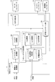
- FIG. 1 is a block diagram showing a configuration of a hybrid car including a vehicle control device (vehicle controller 11) according to an embodiment of the present invention.
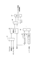
- FIG. 2 is a block diagram showing functional components of the vehicle controller 11.
- FIG. 3 is a flow chart showing a procedure for obtaining the battery drive limit threshold Ft.
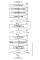
- FIG. 4 is a flow chart showing an operation example of the vehicle controller 11 of FIG.
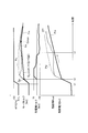
- FIG. 5 is a timing chart showing temporal changes in the accelerator opening APO, the acceleration of the electric vehicle, and the electric power Pm supplied to the drive motor 6.
- FIG. 6 is a timing chart showing temporal changes of each parameter according to the embodiment when the engine 1 is not rotating.
- FIG. 7 is a timing chart showing temporal change of each parameter according to the embodiment when the engine 1 is rotating.
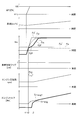
- FIG. 8 is a timing chart explaining the operation and effect according to the embodiment.
- the configuration of an electric vehicle equipped with a vehicle control device will be described with reference to FIG.
- the electric vehicle according to the embodiment includes an engine 1 (internal combustion engine), a generator 4 (first motor) mechanically connected to an output shaft of the engine 1, and a battery 5 electrically connected to the generator 4.
- Drive wheels 7a and 7b for driving an electric vehicle, a drive motor 6 (second motor) mechanically connected to the drive wheels 7a and 7b, a motor controller 12 for controlling the drive motor 6, and a generator 4
- a generator controller 14 for controlling, an engine controller 13 for controlling the engine 1, an engine state sensor 9 for detecting the state of the engine 1 including the number of revolutions and oil temperature of the engine 1, and a wheel speed sensor 3 for detecting wheel speed And an accelerator opening sensor 8 for detecting the accelerator opening APO, and a vehicle controller 11 for controlling the entire powertrain of the electric vehicle.
- the engine 1 does not drive the drive wheels 7a and 7b
- the drive motor 6 drives the drive wheels 7a and 7b.
- the output shaft of the engine 1 is mechanically coupled to the output shaft of the generator 4.
- the generator 4 is electrically connected to the battery 5 and the drive motor 6 so as to transmit and receive electric power (high power).
- the output shaft of the drive motor 6 is mechanically coupled to the axle via the gear 2, and the axle is mechanically coupled to the drive wheels 7a and 7b.
- the engine state sensor 9 transmits the detected engine state to the vehicle controller 11 as an electric signal.
- the engine state sensor 9 includes an engine oil temperature detection sensor and an engine rotational speed detection sensor.
- the wheel speed sensor 3 transmits the detected wheel speed to the vehicle controller 11 as an electric signal.
- the accelerator opening sensor 8 transmits the detected accelerator opening APO to the vehicle controller 11 as an electric signal.
- the driving force of the engine 1 is transmitted to the generator 4, and the generator 4 generates electric power by the driving force of the engine 1.
- the generated power of the generator 4 is transmitted to the drive motor 6 or charged in the battery 5.
- the charge power of the battery 5 is transmitted to the drive motor 6, and the drive motor 6 is driven by the charge power of the battery 5 and the generated power of the generator 4.
- the driving force of the drive motor 6 is transmitted to the drive wheels 7a and 7b via the gear 16 and the axle.
- the drive wheels 7a and 7b are rotated by the drive force of the drive motor 6, whereby the electric vehicle (hereinafter referred to as a vehicle) travels.
- the vehicle controller 11 functions as a vehicle control device according to the embodiment.
- the vehicle controller 11 can be realized by, for example, a general-purpose microcomputer including a CPU (central processing unit), a memory, and an input / output unit.
- a computer program (vehicle control program) for causing the microcomputer to function as the vehicle controller 11 is installed in the microcomputer and executed.
- the general-purpose microcomputer functions as the vehicle controller 11.
- the example which realizes vehicle controller 11 by software is shown, of course, it is also possible to prepare vehicle controller 11 by preparing the hardware for exclusive use for performing each information processing shown below is there.
- the plurality of units (21 to 26, 31 to 35) included in the vehicle controller 11 may be configured by individual hardware.
- vehicle controller 11 not only the vehicle controller 11, but also the motor controller 12, the generator controller 14, and the engine controller 13 can be realized as software or dedicated hardware in the same manner. Furthermore, the vehicle controller 11, the motor controller 12, the generator controller 14, and the engine controller 13 may be shared with an electronic control unit (ECU) used for other control related to the vehicle.
- ECU electronice control unit
- the vehicle controller 11 includes a driving force conversion unit 21, a late limiter processing unit 22, a filter processing unit 23, a stretchness processing unit 24, a safety determination unit 25, and a power generation control unit 26.
- the stretchness processing unit 24 includes a control start determination unit 31, a power generation request unit 32, and a Gj addition unit 33.
- the Gj addition unit 33 includes a Gj1 addition unit 34 and a Gj2 addition unit 35.
- the driving force conversion unit 21 calculates the driving force (driver request driving force) required of the drive motor 6 from the accelerator opening APO detected by the accelerator opening sensor 8 and the wheel speed detected by the wheel speed sensor 3. .
- the vehicle controller 11 is provided in advance with a driving force map (not shown).
- the driving force map is a graph showing the relationship between the vehicle speed and the driver's requested driving force, and the vehicle controller 11 is provided with a driving force map for each accelerator opening.
- the late limiter processing unit 22 performs late limit processing that smoothes the change in the driver request driving force by adding a certain limit to the change rate of the driver request driving force in order to suppress the abrupt change in the driver request driving force. . Thereafter, the filter processing unit 23 applies low-pass filter processing to further smooth the change of the driver request driving force.
- the driver request driving force subjected to the filtering process is input to the stretchness processing unit 24.
- Stretchness is a phenomenon in which a predicted acceleration feeling or smooth acceleration feeling can not be obtained with respect to depression of an accelerator. The “stretchness” will be described later with reference to the graph of FIG.
- the stretchness processing unit 24 sets the drive power Fm output from the drive motor 6 to the maximum power that can be supplied from the battery 5 to drive the vehicle (drive Pout). Limit lower than driving force.
- the power Pout_base that can be supplied by the battery 5
- power (auxiliary device power) consumed by auxiliary equipment such as an air conditioner and audio mounted on the vehicle and the engine 1 are started.
- the value obtained by subtracting the electric power (engine starting electric power) necessary for the vehicle power is the electric power (drive Pout) that the battery 5 can supply as the driving force of the vehicle.
- the drive Pout corresponds to the power that the battery 5 can supply to drive the vehicle.
- the engine starting power corresponds to the power (cranking power) required for the cranking process of the engine 1.
- the engine starting power corresponds to the power (recovery power) required for the recovery process of the engine 1.
- the stretchability processing unit 24 supplies the power saving power Pou_savi, which is lower than the drive power Pout, from the battery 5 to the drive motor 6.
- the driving force Fm output from the driving motor 6 is limited to the battery drive limit threshold Ft lower than the maximum driving force determined from the power that can be supplied by the battery 5 to drive the vehicle.
- the stretchness processing unit 24 starts the engine 1 and the generator 4 starts power generation (t3).
- the driving force Fm output from the driving motor 6 by the power supplied from the battery 5 is increased as time passes as indicated by an arrow Gj1 (first gradient) in FIG.
- the stretchness processing unit 24 supplies the power Pm supplied from the battery 5 to the drive motor 6. Increase over time.
- the driving force Fm output from the driving motor 6 by the power supplied from the battery 5 can be increased as time passes, as indicated by the gradient Gj1 in FIG. 5.
- the rate of increase of the power Pm from the power Pti to the power Pt2 can be calculated from the gradient Gj1 and the vehicle speed in FIG.
- the stretchability processing unit 24 increases the power Pm from the power Pti to the power Pt2 so that the power Pt2 does not become larger than the driving power Pout when the engine 1 starts and the generator 4 starts power generation (t3). And set the power saving power Pou_savi.
- the electric power Pm supplied from the battery 5 to the drive motor 6 is increased according to the passage of time during the period from when the accelerator is depressed to when the engine 1 starts and the generator 4 starts power generation (t1 to t3). be able to.
- the driving force (driving torque) increases with the passage of time and does not stagnate. Therefore, a smooth acceleration feeling is realized by the smooth and continuous rising of the acceleration G.
- a predicted sense of acceleration or smooth sense of acceleration is obtained with respect to the depression of the accelerator, the stretchiness is suppressed, and the discomfort or dissatisfaction of the driver of the vehicle or other occupants is eliminated.
- the stretchness processing unit 24 can set the power saving power Pou_savi to a value obtained by subtracting the surplus power Pdown determined by the time required for starting the engine 1 from the driving power Pout.
- the battery drive limit threshold Ft is set to a value obtained by subtracting the surplus driving force determined by the time required for starting the engine 1 from the maximum driving force determined from the power that can be supplied for the battery 5 to drive the vehicle. be able to.
- the battery drive limit threshold Ft can be estimated accurately.
- the time required for starting the engine 1 (the cranking period Cra) is the time (t2 to t3) required for the determination of the start of the engine 1 and the cranking process of the engine 1.
- the cranking period Cra can be estimated based on the engine oil temperature.
- “EV” in FIG. 5 indicates the EV state before determination of the start of the engine 1
- “Gen” indicates the power generation state after the start of the engine 1.
- the stretchability processing unit 24 may determine the surplus power Pdown not only by the time required to start the engine 1 but also by referring to the rate of increase of the power Pm. That is, the stretchability processing unit 24 can set the power saving power Pou_savi to a value obtained by subtracting the surplus power Pdown determined by the time required for starting the engine 1 and the increase rate of the power Pm from the driving Pout. Specifically, surplus power Pdown is calculated by multiplying the increase rate of power Pm by the time required to start engine 1.
- the battery drive limit threshold Ft is determined by the time required for starting the engine 1 and the first gradient (Gj1) of the drive force from the maximum drive force determined from the power that the battery 5 can supply to drive the vehicle. It can be set to a value obtained by subtracting the excess driving force. Thus, the battery drive limit threshold Ft can be estimated more accurately.
- the maximum value of the power that can be supplied to the drive motor 6 is the drive Pout until the engine 1 starts and the generator 4 starts power generation ( ⁇ t3).
- the electric power Pcon generated by the generator 4 is added to the driving Pout after the engine 1 is started and the generator 4 starts power generation (from t3 on)
- the electric motor for driving the electric power more than the driving Pout 6 can be supplied.
- the rotation speed of the engine 1 is controlled to increase the electric power Pcon, thereby bringing the electric power Pm supplied to the drive motor 6 closer to the driver request electric power Pd.
- the driving force Fm driving torque
- Gmax the maximum value Gmax by increasing the power Pm with time without delaying it. It can be smoothly increased with the passage of time without stagnation.
- the control start determination unit 31 determines the stretchability. It is determined that there is a possibility of occurrence, and processing to suppress stretch is started. Specifically, as the accelerator opening APO increases, the driving force Fm required of the driving motor 6 also increases. When the driver request driving force is equal to or more than the battery drive limit threshold Ft, the control start determination unit 31 starts the process for starting the engine 1. If the driving force Fm is less than the battery drive limit threshold Ft, the process for starting the engine 1 is not started. This makes it possible to properly determine the necessity of starting the engine 1. At this time, fuel is not supplied to the engine 1, and the engine 1 is not in a combustion state. Furthermore, the output shaft of the engine 1 is not rotating, and the engine 1 is at rest.
- the control start determination unit 31 starts the engine 1 when the driving force Fm required for the drive motor 6 becomes lower than the battery drive limit threshold Ft. Interrupt the process to For example, it corresponds to the case of returning the accelerator once depressed. This makes it possible to properly determine the necessity of starting the engine 1.
- the battery drive limit threshold Ft has a certain hysteresis when determining the start and the stop of the start processing of the engine 1.
- the control start determination unit 31 outputs the determination result of the engine start as a start determination flag to the Gj addition unit 33 and the power generation control unit 26. At the same time, the control start determination unit 31 outputs the time required for starting the engine 1 (cranking time) to the Gj addition unit 33 and the power generation control unit 26.
- the Gj1 addition unit 34 calculates a battery drive limit threshold Ft. Specifically, the Gj1 addition unit 34 calculates the surplus power Pdown from the cranking time obtained from the engine oil temperature. Then, the power saving power Pou_savi is obtained by subtracting the surplus power Pdown from the driving power Pout, and the battery drive limiting threshold Ft is calculated from the power saving power Pou_savi and the vehicle speed.
- the Gj1 addition unit 34 increases the driving force Fm with the first gradient (Gj1) after the driving force Fm reaches the battery drive limit threshold Ft.
- the increase of the driving force Fm at the first gradient (Gj1) is performed until the engine 1 starts ( ⁇ t3).
- the increase of the driving force Fm at the first gradient (Gj1) corresponds to the excess driving force determined by the time required to start the engine 1 and is filled with the surplus electric power Pdown.
- the Gj1 addition unit 34 calculates the rate of increase of the power Pm required to increase the driving force Fm at the first gradient (Gj1).
- the Gj2 addition unit 35 increases the driving force Fm at the second gradient (Gj2) after the engine 1 is started (t3 and after).
- the increase of the driving force Fm at the second gradient (Gj2) is filled with the power (consumable power Pcon) generated by the generator 4.
- the Gj2 addition unit 35 calculates an increase rate of the consumable power Pcon necessary to increase the driving force Fm at the second gradient (Gj2).
- the Gj addition unit 33 is required to increase the driving power Fm at the second gradient (Gj2) and the rate of increase of the power Pm required to increase the driving power Fm at the first gradient (Gj1) with the power saving power Pou_savi.
- the increase rate of the consumable power Pcon is transmitted to the safety determination unit 25 and the power generation control unit 26, respectively.
- the power generation request unit 32 requests the rotation of the output shaft of the engine 1 when the battery drive restriction threshold Ft becomes lower than a predetermined lower limit driving force Fa.
- the battery drive restriction threshold Ft becomes lower than a predetermined lower limit driving force Fa.
- SOC state of charge
- the driving Pout decreases, so the battery drive limit threshold Ft also decreases.
- the output shaft of the engine 1 is previously rotated in preparation for the future power generation request. By rotating the output shaft in advance, the time required for starting the engine 1 can be shortened as compared to the non-rotating state.
- rotation of the output shaft refers not only to the firing control that supplies fuel to the engine to start the engine, but also causes the generator 4 to forcibly rotate the rotation shaft of the engine 1 that has shut off the fuel supply. It is a concept that also includes motoring control.
- the power generation request unit 32 previously limits the number of revolutions when the output shaft of the engine 1 is rotated to the number of revolutions necessary for the generator 4 to generate a predetermined lower limit generated power.
- This number of revolutions is the number of revolutions at which the lower limit generated power can be generated when power is generated at the maximum engine torque.
- the lower limit value of the number of revolutions when rotating the output shaft of the engine 1 is set in advance to the number of revolutions necessary for the generator 4 to generate a predetermined lower limit generated power.
- the fuel supplied to the engine 1 for rotation and the power consumed by the generator 4 can be secured.
- the power generation request unit 32 can determine the predetermined lower limit generated power from the driving force that causes the acceleration change greater than or equal to the predetermined power and the power that can be supplied by the battery. Specifically, the power generation request unit 32 sets the difference between the generated power necessary for the drive motor 6 to output the driving force that causes the change amount of the predetermined acceleration and the power that can be supplied from the battery to be a predetermined lower limit generated power value. Set as. When the amount of change in acceleration is small, it is possible to prevent dissatisfaction that the driver can not sense the acceleration G of the vehicle predicted for depression of the accelerator.
- the power generation request unit 32 is the upper limit value of the power generated by the generator 4 so that the surplus power obtained by subtracting the power used by the vehicle from the power generated by the generator 4 becomes equal to or less than the power that the battery 5 can charge.
- Set the upper limit generated power That is, the power generation request unit 32 can determine the upper limit generated power from the power that the battery 5 can charge.
- the power generated by the generator 4 is limited to the upper limit generated power or less. Specifically, the power generation request unit 32 generates the surplus power when the generated power exceeds the power used in the vehicle relative to the power generated by the generator 4 in order to make the surplus power smaller than the chargeable power of the battery 5.
- Set a predetermined upper limit generated power value is the upper limit generated power value.
- the power generation request unit 32 transmits a rotation request for the output shaft of the engine 1, the upper limit generated power, and the lower limit generated power to the power generation control unit 26.
- the safety judgment unit 25 is required to increase the driving power Fm by the second gradient (Gj2) and the increase rate of the power Pm required to increase the driving power Fm by the power saving power Pou_savi, the first gradient (Gj1). It is determined whether the rate of increase of the consumable power Pcon satisfies the condition for operating the drive motor 6 safely, and the necessary processing for safe operation is performed. After the safety determination unit 25 performs these determinations and processes, the increase rate of the power Pm necessary for increasing the driving force Fm with the power saving power Pou_savi and the first gradient (Gj1) to the motor controller 12; And the second gradient (Gj2) indicates the rate of increase of the consumable power Pcon required to increase the driving force Fm.
- the power generation control unit 26 instructs the engine controller 13 to start the engine 1, and the rotation of the engine based on the rate of increase of the consumable power Pcon required to increase the driving force Fm at the second gradient (Gj2). Indicate the number.
- the power generation control unit 26 instructs the generator controller 14 to rotate the output shaft of the engine 1 by motoring control.
- the stretchability processing unit 24 obtains the drive Pout by subtracting the power (auxiliary device power) and the cranking power (or recovery power) consumed by the accessory from the power Pout_base.
- step 42 the stretchability processing unit 24 obtains the driving force (driving torque) of the vehicle obtained from the driving Pout from the vehicle speed and the driving Pout using the driving force map.
- the stretchability processing unit 24 obtains the excess driving force by multiplying the first gradient Gj1 (Gj1 torque rate value 43) by the time required for starting the engine 1 (the cranking time 44).
- the stretchness processing unit 24 obtains the battery drive limit threshold Ft by subtracting the excess driving force from the driving force of the vehicle obtained from the driving Pout.
- step 47 the stretchability processing unit 24 compares the battery drive limit threshold Ft, the creep torque, and zero and selects the largest value.
- the stretchability processing unit 24 sets the battery drive limit threshold Ft to the power running side, which is larger than the drive force output by the drive motor 6 when the accelerator of the vehicle is in the off state. This can prevent the engine 1 from operating continuously when the accelerator is in the off state. Further, the drive motor 6 can be maintained in the state of outputting positive torque, that is, in the power running state.
- the stretchness processing unit 24 can obtain the battery drive limit threshold Ft.
- step 01 the vehicle controller 11 reads input signals indicating the accelerator opening APO, the shift position, the vehicle speed, the engine oil temperature, the state of charge (SOC) of the battery 5, and the power Pout_base.
- the vehicle controller 11 calculates the driver request driving force Fd based on the accelerator opening degree, the vehicle speed and the shift position.
- the battery drive limit threshold Ft is calculated.
- the lower limit driving force Fa is calculated.
- step S09 the vehicle controller 11 (power generation request unit 32) determines whether the battery drive limit threshold Ft is lower than the lower limit driving force Fa. If the determination is affirmative (YES in S09), the process proceeds to step S11, and if the determination is negative (NO in S09), the process proceeds to step S13.
- step S11 the vehicle controller 11 (the power generation request unit 32) requests the rotation of the output shaft of the engine 1.
- the battery drive limit threshold Ft becomes low, the possibility of the power generation request to the generator 4 also increases, so the output shaft of the engine 1 is previously rotated in preparation for the future power generation request. Thereafter, the process proceeds to step S13.
- step S13 the vehicle controller 11 determines whether the driver request driving force Fd is higher than the battery drive limit threshold Ft. In the case of a positive determination (YES in S13), it is determined that there is a possibility that stretchness will occur, and the process proceeds to step S15. On the other hand, in the case of a negative determination (NO in S13), it is determined that there is no possibility of occurrence of stretchness, and the flowchart of FIG. 4 ends.
- step S15 processing for suppressing the stretchiness, specifically, processing for starting the engine 1 (cranking processing or recovery processing) is started.
- step S17 the driving force rate limit values (Gj1, Gj2) are calculated with reference to the vehicle speed.
- step S19 the Gj addition unit 33 calculates a driving force Fm subjected to a rate limit process for limiting the gradient (Gj1, Gj2) of the driving force at the time of acceleration.
- step S21 the vehicle controller 11 determines whether the driving force Fm has reached the driver's requested driving force Fd. In the case of a positive determination (YES in S21), the control by the vehicle controller 11 ends. In the case of a negative determination (NO in S21), the process returns to step S19.
- the time change of each parameter when the accelerator is depressed in a state where the engine 1 is not rotating (an example of “a state where the engine 1 is stopped”) will be described with reference to the timing chart of FIG.
- the accelerator opening APO rises (t1).
- the driver request driving force (Fd, Fd ') rises.
- the driver request driving force Fd is obtained by performing rate limit processing on the driver request driving force Fd 'by the late limiter processing unit 22 and the filter processing unit 23.
- the driving force Fm output by the driving motor 6 also increases after the response time.
- the driver request driving force Fd exceeds the battery drive limit threshold Ft (t2)
- the power generation start flag changes from the theoretical value 0 to the theoretical value 1 and a process (cranking period: Cra) for starting the engine 1 Start.
- the rotation speed of the engine 1 is increased.
- the target driving force Tr_eng * of the engine 1 rises.
- the actual driving force Tr_eng actually output by the engine 1 has a negative value.
- the rise of the driving force Fm is limited to the battery drive limit threshold Ft (not shown).
- the driving force Fm output by the drive motor 6 increases at the first gradient Gj1.
- the driving force Fm output by the driving motor 6 increases at the second gradient Gj2.
- the first gradient Gj1 is made smaller than the second gradient Gj2 for the first gradient Gj1 and the second gradient Gj2 that indicate the amount of increase per unit time of the driving force Fm.
- the drive motor 6 After the drive motor 6 outputs a low limited drive force (battery drive limit threshold Ft), the drive motor 6 outputs power during a period until the engine 1 starts and the generator 4 starts power generation (t2 to t3).
- the first gradient Gj1 of the driving force Fm is made smaller than the second gradient Gj2 of the driving force output from the driving motor 6 after the generator 4 starts power generation (from t3).
- the increase of the driving force Fm at the second gradient Gj2 continues until the driving force Fm reaches the driver's required driving force Fd.
- the generator 4 starts generating power (from t3)
- the actual driving force Tr_eng becomes the power running side
- the number of revolutions of the engine increases with the passage of time.
- the vehicle speed increases with the passage of time due to the generation and increase of the driving force Fm.
- the “state in which the engine 1 is stopped” indicates a state in which the engine 1 is not started, that is, a state in which the fuel is not supplied to the engine 1. It does not matter whether or not the output shaft of the engine 1 is rotating in the "state in which the engine 1 is stopped”.
- the effects of the embodiment will be described with reference to the timing chart of FIG.
- the curve pm shows the time change of the power pm according to the comparative example
- the curve Pm shows the time change of the power Pm according to the embodiment.
- the curve fm shows the time change of the driving force (driving torque fm) according to the comparative example
- the curve Fm shows the time change of the driving force (driving torque Fm) according to the embodiment.
- the power indicates the power supplied to the drive motor 6.
- the power pm of the comparative example increases to the driving Pout along the driver required power Pd.
- the power pm of the comparative example stagnates around the driving Pout until power generation is started ( ⁇ t3).
- the driving torque fm according to the comparative example increases to a certain value by increasing the power pm to the driving Pout, but then decreases due to stagnation of the power pm and when the engine 1 is started, Start to increase again.
- the shape of the curve showing the time change of the drive torque fm according to the comparative example is not similar to the shape of the curve showing the time change of the driver request drive force Fd. It can not be said that the curve of the driving torque fm according to the comparative example is increasing and decreasing repeatedly and rising smoothly and continuously. As a result, the driver may feel uncomfortable or dissatisfied with the driver or other occupants of the vehicle without obtaining a predicted sense of acceleration or a smooth sense of acceleration with respect to depression of the accelerator.
- the power Pm of the embodiment rises along the driver request power Pd, but is limited to a value (power saving power Pou_savi) lower than the driving Pout. Then, after the power Pm limited lower than the drive Pout is supplied to the drive motor 6, the battery 5 supplies power until the engine 1 starts and the generator 4 starts power generation (t2 to t3). The power Pm is increased as time passes, as indicated by the arrows in FIG. At this time, the rate of increase of the power Pm and the power saving power Pou_savi are set so that the power Pm at time t3 when the engine 1 starts and the generator 4 starts power generation does not become larger than the driving Pout.
- a value power saving power Pou_savi
- the drive torque Fm according to the embodiment increases with the passage of time without stagnation until the engine 1 starts (up to t3).
- the shape of the curve showing the time change of the drive torque Fm according to the embodiment is similar to the shape of the curve showing the time change of the driver request driving force Fd.
- the curve of the drive torque Fm according to the embodiment rises smoothly and continuously. For this reason, a sense of acceleration predicted for the depression of the accelerator or a smooth sense of acceleration can be obtained, and the discomfort or dissatisfaction felt by the driver or other occupants of the vehicle can be suppressed.
- the processing circuitry comprises a programmed processing device, such as a processing device that includes an electrical circuit.
- the processing device also includes devices such as application specific integrated circuits (ASICs) and conventional circuit components arranged to perform the functions described in the embodiments.
- ASICs application specific integrated circuits
Landscapes
- Engineering & Computer Science (AREA)
- Mechanical Engineering (AREA)
- Chemical & Material Sciences (AREA)
- Combustion & Propulsion (AREA)
- Transportation (AREA)
- Automation & Control Theory (AREA)
- General Engineering & Computer Science (AREA)
- Electric Propulsion And Braking For Vehicles (AREA)
- Hybrid Electric Vehicles (AREA)
- Charge And Discharge Circuits For Batteries Or The Like (AREA)
Abstract
Priority Applications (9)
| Application Number | Priority Date | Filing Date | Title |
|---|---|---|---|
| CN201780097641.5A CN111479735B (zh) | 2017-12-15 | 2017-12-15 | 车辆控制方法和车辆控制装置 |
| MX2020006234A MX2020006234A (es) | 2017-12-15 | 2017-12-15 | Metodo de control de vehiculo y dispositivo de control de vehiculo. |
| BR112020011848-6A BR112020011848B1 (pt) | 2017-12-15 | Método de controle de veículo e dispositivo de controle de veículo | |
| RU2020123239A RU2748238C1 (ru) | 2017-12-15 | 2017-12-15 | Способ управления электроприводом транспортного средства и устройство управления электроприводом транспортного средства |
| EP17934487.4A EP3725618B1 (fr) | 2017-12-15 | 2017-12-15 | Procédé et dispositif de commande de véhicule |
| PCT/JP2017/045163 WO2019116552A1 (fr) | 2017-12-15 | 2017-12-15 | Procédé et dispositif de commande de véhicule |
| JP2019558842A JP6927326B2 (ja) | 2017-12-15 | 2017-12-15 | 車両制御方法及び車両制御装置 |
| KR1020207018405A KR102362854B1 (ko) | 2017-12-15 | 2017-12-15 | 차량 제어 방법 및 차량 제어 장치 |
| US16/771,337 US11465604B2 (en) | 2017-12-15 | 2017-12-15 | Vehicle control method and vehicle control device |
Applications Claiming Priority (1)
| Application Number | Priority Date | Filing Date | Title |
|---|---|---|---|
| PCT/JP2017/045163 WO2019116552A1 (fr) | 2017-12-15 | 2017-12-15 | Procédé et dispositif de commande de véhicule |
Publications (1)
| Publication Number | Publication Date |
|---|---|
| WO2019116552A1 true WO2019116552A1 (fr) | 2019-06-20 |
Family
ID=66819106
Family Applications (1)
| Application Number | Title | Priority Date | Filing Date |
|---|---|---|---|
| PCT/JP2017/045163 Ceased WO2019116552A1 (fr) | 2017-12-15 | 2017-12-15 | Procédé et dispositif de commande de véhicule |
Country Status (8)
| Country | Link |
|---|---|
| US (1) | US11465604B2 (fr) |
| EP (1) | EP3725618B1 (fr) |
| JP (1) | JP6927326B2 (fr) |
| KR (1) | KR102362854B1 (fr) |
| CN (1) | CN111479735B (fr) |
| MX (1) | MX2020006234A (fr) |
| RU (1) | RU2748238C1 (fr) |
| WO (1) | WO2019116552A1 (fr) |
Cited By (1)
| Publication number | Priority date | Publication date | Assignee | Title |
|---|---|---|---|---|
| JP2022023457A (ja) * | 2020-07-27 | 2022-02-08 | 三菱自動車工業株式会社 | 車両の走行制御システム、及びハイブリッド車両 |
Families Citing this family (1)
| Publication number | Priority date | Publication date | Assignee | Title |
|---|---|---|---|---|
| DE102018208425B4 (de) * | 2018-05-28 | 2026-01-29 | Bayerische Motoren Werke Aktiengesellschaft | Antriebsstrang für ein Kraftfahrzeug, insbesondere für einen Kraftwagen, sowie Verfahren zum Betreiben eines solchen Antriebsstrangs |
Citations (6)
| Publication number | Priority date | Publication date | Assignee | Title |
|---|---|---|---|---|
| JP2000179371A (ja) | 1998-12-15 | 2000-06-27 | Nissan Motor Co Ltd | 車両の駆動力制御装置 |
| JP2010179882A (ja) * | 2009-02-09 | 2010-08-19 | Nissan Motor Co Ltd | 車両の再始動制御装置及び再始動制御方法 |
| JP2013129313A (ja) * | 2011-12-21 | 2013-07-04 | Suzuki Motor Corp | エンジン始動制御装置 |
| JP2013189048A (ja) * | 2012-03-13 | 2013-09-26 | Toyota Motor Corp | ハイブリッド車両の制御装置 |
| WO2014006717A1 (fr) * | 2012-07-05 | 2014-01-09 | トヨタ自動車株式会社 | Dispositif de commande pour véhicule hybride |
| JP2015093663A (ja) * | 2013-11-14 | 2015-05-18 | 日産自動車株式会社 | ハイブリッド車両の制御装置 |
Family Cites Families (7)
| Publication number | Priority date | Publication date | Assignee | Title |
|---|---|---|---|---|
| JP5305025B2 (ja) * | 2009-07-06 | 2013-10-02 | スズキ株式会社 | ハイブリッド車両 |
| CN102958740B (zh) * | 2010-06-25 | 2014-11-12 | 丰田自动车株式会社 | 电动车辆及其控制方法 |
| EP2772398B1 (fr) * | 2011-10-28 | 2018-11-14 | Nissan Motor Co., Ltd | Dispositif de commande pour véhicule hybride |
| WO2013137278A1 (fr) * | 2012-03-15 | 2013-09-19 | 日産自動車株式会社 | Appareil de commande de véhicule hybride |
| JP2014177255A (ja) * | 2013-03-15 | 2014-09-25 | Aisin Seiki Co Ltd | 車両制御装置 |
| JP2015202727A (ja) * | 2014-04-11 | 2015-11-16 | トヨタ自動車株式会社 | 車両 |
| JP6315016B2 (ja) | 2016-03-25 | 2018-04-25 | トヨタ自動車株式会社 | ハイブリッド車両の制御装置 |
-
2017
- 2017-12-15 KR KR1020207018405A patent/KR102362854B1/ko not_active Expired - Fee Related
- 2017-12-15 CN CN201780097641.5A patent/CN111479735B/zh active Active
- 2017-12-15 MX MX2020006234A patent/MX2020006234A/es unknown
- 2017-12-15 US US16/771,337 patent/US11465604B2/en active Active
- 2017-12-15 WO PCT/JP2017/045163 patent/WO2019116552A1/fr not_active Ceased
- 2017-12-15 RU RU2020123239A patent/RU2748238C1/ru active
- 2017-12-15 EP EP17934487.4A patent/EP3725618B1/fr active Active
- 2017-12-15 JP JP2019558842A patent/JP6927326B2/ja active Active
Patent Citations (6)
| Publication number | Priority date | Publication date | Assignee | Title |
|---|---|---|---|---|
| JP2000179371A (ja) | 1998-12-15 | 2000-06-27 | Nissan Motor Co Ltd | 車両の駆動力制御装置 |
| JP2010179882A (ja) * | 2009-02-09 | 2010-08-19 | Nissan Motor Co Ltd | 車両の再始動制御装置及び再始動制御方法 |
| JP2013129313A (ja) * | 2011-12-21 | 2013-07-04 | Suzuki Motor Corp | エンジン始動制御装置 |
| JP2013189048A (ja) * | 2012-03-13 | 2013-09-26 | Toyota Motor Corp | ハイブリッド車両の制御装置 |
| WO2014006717A1 (fr) * | 2012-07-05 | 2014-01-09 | トヨタ自動車株式会社 | Dispositif de commande pour véhicule hybride |
| JP2015093663A (ja) * | 2013-11-14 | 2015-05-18 | 日産自動車株式会社 | ハイブリッド車両の制御装置 |
Non-Patent Citations (1)
| Title |
|---|
| See also references of EP3725618A4 |
Cited By (2)
| Publication number | Priority date | Publication date | Assignee | Title |
|---|---|---|---|---|
| JP2022023457A (ja) * | 2020-07-27 | 2022-02-08 | 三菱自動車工業株式会社 | 車両の走行制御システム、及びハイブリッド車両 |
| JP7424238B2 (ja) | 2020-07-27 | 2024-01-30 | 三菱自動車工業株式会社 | 車両の走行制御システム、及びハイブリッド車両 |
Also Published As
| Publication number | Publication date |
|---|---|
| EP3725618A1 (fr) | 2020-10-21 |
| US20200339097A1 (en) | 2020-10-29 |
| BR112020011848A2 (pt) | 2020-11-24 |
| KR102362854B1 (ko) | 2022-02-15 |
| US11465604B2 (en) | 2022-10-11 |
| CN111479735B (zh) | 2023-06-06 |
| RU2748238C1 (ru) | 2021-05-21 |
| JPWO2019116552A1 (ja) | 2021-01-14 |
| EP3725618A4 (fr) | 2020-12-16 |
| KR20200088468A (ko) | 2020-07-22 |
| JP6927326B2 (ja) | 2021-08-25 |
| CN111479735A (zh) | 2020-07-31 |
| EP3725618B1 (fr) | 2022-08-24 |
| MX2020006234A (es) | 2020-08-24 |
Similar Documents
| Publication | Publication Date | Title |
|---|---|---|
| JP3539406B2 (ja) | ハイブリッド車両の制御装置 | |
| CN103858311B (zh) | 充电控制装置及充电控制方法 | |
| US9604623B2 (en) | Drive control system for electric motor and method of controlling electric motor | |
| KR101588789B1 (ko) | 구동 모터를 구비한 차량의 크립 토크 제어 방법 및 장치 | |
| CN109476235B (zh) | 转矩控制方法以及转矩控制装置 | |
| US10286896B2 (en) | Hybrid vehicle | |
| RU2750051C1 (ru) | Способ управления рекуперативным торможением и устройство управления рекуперативным торможением | |
| JP2004135417A (ja) | 車輌の制御装置 | |
| US10322714B2 (en) | Hybrid vehicle and control method for same | |
| CN113924238B (zh) | 电动装置控制方法以及电动装置 | |
| US20170021822A1 (en) | Vehicle | |
| CN114286768B (zh) | 串联混合动力车辆的控制方法以及串联混合动力车辆 | |
| JP6927326B2 (ja) | 車両制御方法及び車両制御装置 | |
| JP3870928B2 (ja) | 自動車のバッテリー制御装置 | |
| JP5510662B2 (ja) | 車両の制御装置 | |
| JP2006275019A (ja) | ハイブリッド車の制御装置 | |
| KR101637304B1 (ko) | 토크 지령 생성 방법 및 장치 | |
| JP6192191B2 (ja) | Isgを用いたエンジントルク補助装置およびトルク補助方法 | |
| JP6227465B2 (ja) | エンジン制御装置及びハイブリッド自動車 | |
| JP6075284B2 (ja) | 車両用電源制御装置 | |
| JP5699841B2 (ja) | ハイブリッド自動車 | |
| JP2015101120A (ja) | 車両 | |
| JP3994904B2 (ja) | ハイブリッド車両の制御装置 | |
| JP2019123471A (ja) | 車両用制御装置 | |
| JP2011126421A (ja) | 車両駆動システムの制御装置 |
Legal Events
| Date | Code | Title | Description |
|---|---|---|---|
| 121 | Ep: the epo has been informed by wipo that ep was designated in this application |
Ref document number: 17934487 Country of ref document: EP Kind code of ref document: A1 |
|
| ENP | Entry into the national phase |
Ref document number: 2019558842 Country of ref document: JP Kind code of ref document: A |
|
| NENP | Non-entry into the national phase |
Ref country code: DE |
|
| ENP | Entry into the national phase |
Ref document number: 20207018405 Country of ref document: KR Kind code of ref document: A |
|
| ENP | Entry into the national phase |
Ref document number: 2017934487 Country of ref document: EP Effective date: 20200715 |
|
| REG | Reference to national code |
Ref country code: BR Ref legal event code: B01A Ref document number: 112020011848 Country of ref document: BR |
|
| ENP | Entry into the national phase |
Ref document number: 112020011848 Country of ref document: BR Kind code of ref document: A2 Effective date: 20200612 |