WO2019116553A1 - 回生ブレーキ制御方法及び回生ブレーキ制御装置 - Google Patents
回生ブレーキ制御方法及び回生ブレーキ制御装置 Download PDFInfo
- Publication number
- WO2019116553A1 WO2019116553A1 PCT/JP2017/045164 JP2017045164W WO2019116553A1 WO 2019116553 A1 WO2019116553 A1 WO 2019116553A1 JP 2017045164 W JP2017045164 W JP 2017045164W WO 2019116553 A1 WO2019116553 A1 WO 2019116553A1
- Authority
- WO
- WIPO (PCT)
- Prior art keywords
- regenerative
- upper limit
- control method
- operation mode
- brake control
- Prior art date
- Legal status (The legal status is an assumption and is not a legal conclusion. Google has not performed a legal analysis and makes no representation as to the accuracy of the status listed.)
- Ceased
Links
Images
Classifications
-
- F—MECHANICAL ENGINEERING; LIGHTING; HEATING; WEAPONS; BLASTING
- F16—ENGINEERING ELEMENTS AND UNITS; GENERAL MEASURES FOR PRODUCING AND MAINTAINING EFFECTIVE FUNCTIONING OF MACHINES OR INSTALLATIONS; THERMAL INSULATION IN GENERAL
- F16D—COUPLINGS FOR TRANSMITTING ROTATION; CLUTCHES; BRAKES
- F16D61/00—Brakes with means for making the energy absorbed available for use
-
- B—PERFORMING OPERATIONS; TRANSPORTING
- B60—VEHICLES IN GENERAL
- B60L—PROPULSION OF ELECTRICALLY-PROPELLED VEHICLES; SUPPLYING ELECTRIC POWER FOR AUXILIARY EQUIPMENT OF ELECTRICALLY-PROPELLED VEHICLES; ELECTRODYNAMIC BRAKE SYSTEMS FOR VEHICLES IN GENERAL; MAGNETIC SUSPENSION OR LEVITATION FOR VEHICLES; MONITORING OPERATING VARIABLES OF ELECTRICALLY-PROPELLED VEHICLES; ELECTRIC SAFETY DEVICES FOR ELECTRICALLY-PROPELLED VEHICLES
- B60L7/00—Electrodynamic brake systems for vehicles in general
- B60L7/10—Dynamic electric regenerative braking
-
- B—PERFORMING OPERATIONS; TRANSPORTING
- B60—VEHICLES IN GENERAL
- B60K—ARRANGEMENT OR MOUNTING OF PROPULSION UNITS OR OF TRANSMISSIONS IN VEHICLES; ARRANGEMENT OR MOUNTING OF PLURAL DIVERSE PRIME-MOVERS IN VEHICLES; AUXILIARY DRIVES FOR VEHICLES; INSTRUMENTATION OR DASHBOARDS FOR VEHICLES; ARRANGEMENTS IN CONNECTION WITH COOLING, AIR INTAKE, GAS EXHAUST OR FUEL SUPPLY OF PROPULSION UNITS IN VEHICLES
- B60K6/00—Arrangement or mounting of plural diverse prime-movers for mutual or common propulsion, e.g. hybrid propulsion systems comprising electric motors and internal combustion engines
- B60K6/20—Arrangement or mounting of plural diverse prime-movers for mutual or common propulsion, e.g. hybrid propulsion systems comprising electric motors and internal combustion engines the prime-movers consisting of electric motors and internal combustion engines, e.g. HEVs
- B60K6/42—Arrangement or mounting of plural diverse prime-movers for mutual or common propulsion, e.g. hybrid propulsion systems comprising electric motors and internal combustion engines the prime-movers consisting of electric motors and internal combustion engines, e.g. HEVs characterised by the architecture of the hybrid electric vehicle
- B60K6/46—Series type
-
- B—PERFORMING OPERATIONS; TRANSPORTING
- B60—VEHICLES IN GENERAL
- B60L—PROPULSION OF ELECTRICALLY-PROPELLED VEHICLES; SUPPLYING ELECTRIC POWER FOR AUXILIARY EQUIPMENT OF ELECTRICALLY-PROPELLED VEHICLES; ELECTRODYNAMIC BRAKE SYSTEMS FOR VEHICLES IN GENERAL; MAGNETIC SUSPENSION OR LEVITATION FOR VEHICLES; MONITORING OPERATING VARIABLES OF ELECTRICALLY-PROPELLED VEHICLES; ELECTRIC SAFETY DEVICES FOR ELECTRICALLY-PROPELLED VEHICLES
- B60L15/00—Methods, circuits, or devices for controlling the traction-motor speed of electrically-propelled vehicles
- B60L15/20—Methods, circuits, or devices for controlling the traction-motor speed of electrically-propelled vehicles for control of the vehicle or its driving motor to achieve a desired performance, e.g. speed, torque, programmed variation of speed
- B60L15/2045—Methods, circuits, or devices for controlling the traction-motor speed of electrically-propelled vehicles for control of the vehicle or its driving motor to achieve a desired performance, e.g. speed, torque, programmed variation of speed for optimising the use of energy
-
- B—PERFORMING OPERATIONS; TRANSPORTING
- B60—VEHICLES IN GENERAL
- B60L—PROPULSION OF ELECTRICALLY-PROPELLED VEHICLES; SUPPLYING ELECTRIC POWER FOR AUXILIARY EQUIPMENT OF ELECTRICALLY-PROPELLED VEHICLES; ELECTRODYNAMIC BRAKE SYSTEMS FOR VEHICLES IN GENERAL; MAGNETIC SUSPENSION OR LEVITATION FOR VEHICLES; MONITORING OPERATING VARIABLES OF ELECTRICALLY-PROPELLED VEHICLES; ELECTRIC SAFETY DEVICES FOR ELECTRICALLY-PROPELLED VEHICLES
- B60L50/00—Electric propulsion with power supplied within the vehicle
- B60L50/10—Electric propulsion with power supplied within the vehicle using propulsion power supplied by engine-driven generators, e.g. generators driven by combustion engines
-
- B—PERFORMING OPERATIONS; TRANSPORTING
- B60—VEHICLES IN GENERAL
- B60L—PROPULSION OF ELECTRICALLY-PROPELLED VEHICLES; SUPPLYING ELECTRIC POWER FOR AUXILIARY EQUIPMENT OF ELECTRICALLY-PROPELLED VEHICLES; ELECTRODYNAMIC BRAKE SYSTEMS FOR VEHICLES IN GENERAL; MAGNETIC SUSPENSION OR LEVITATION FOR VEHICLES; MONITORING OPERATING VARIABLES OF ELECTRICALLY-PROPELLED VEHICLES; ELECTRIC SAFETY DEVICES FOR ELECTRICALLY-PROPELLED VEHICLES
- B60L50/00—Electric propulsion with power supplied within the vehicle
- B60L50/50—Electric propulsion with power supplied within the vehicle using propulsion power supplied by batteries or fuel cells
- B60L50/60—Electric propulsion with power supplied within the vehicle using propulsion power supplied by batteries or fuel cells using power supplied by batteries
- B60L50/61—Electric propulsion with power supplied within the vehicle using propulsion power supplied by batteries or fuel cells using power supplied by batteries by batteries charged by engine-driven generators, e.g. series hybrid electric vehicles
-
- B—PERFORMING OPERATIONS; TRANSPORTING
- B60—VEHICLES IN GENERAL
- B60L—PROPULSION OF ELECTRICALLY-PROPELLED VEHICLES; SUPPLYING ELECTRIC POWER FOR AUXILIARY EQUIPMENT OF ELECTRICALLY-PROPELLED VEHICLES; ELECTRODYNAMIC BRAKE SYSTEMS FOR VEHICLES IN GENERAL; MAGNETIC SUSPENSION OR LEVITATION FOR VEHICLES; MONITORING OPERATING VARIABLES OF ELECTRICALLY-PROPELLED VEHICLES; ELECTRIC SAFETY DEVICES FOR ELECTRICALLY-PROPELLED VEHICLES
- B60L58/00—Methods or circuit arrangements for monitoring or controlling batteries or fuel cells, specially adapted for electric vehicles
- B60L58/10—Methods or circuit arrangements for monitoring or controlling batteries or fuel cells, specially adapted for electric vehicles for monitoring or controlling batteries
- B60L58/12—Methods or circuit arrangements for monitoring or controlling batteries or fuel cells, specially adapted for electric vehicles for monitoring or controlling batteries responding to state of charge [SoC]
-
- B—PERFORMING OPERATIONS; TRANSPORTING
- B60—VEHICLES IN GENERAL
- B60L—PROPULSION OF ELECTRICALLY-PROPELLED VEHICLES; SUPPLYING ELECTRIC POWER FOR AUXILIARY EQUIPMENT OF ELECTRICALLY-PROPELLED VEHICLES; ELECTRODYNAMIC BRAKE SYSTEMS FOR VEHICLES IN GENERAL; MAGNETIC SUSPENSION OR LEVITATION FOR VEHICLES; MONITORING OPERATING VARIABLES OF ELECTRICALLY-PROPELLED VEHICLES; ELECTRIC SAFETY DEVICES FOR ELECTRICALLY-PROPELLED VEHICLES
- B60L7/00—Electrodynamic brake systems for vehicles in general
- B60L7/10—Dynamic electric regenerative braking
- B60L7/18—Controlling the braking effect
-
- B—PERFORMING OPERATIONS; TRANSPORTING
- B60—VEHICLES IN GENERAL
- B60L—PROPULSION OF ELECTRICALLY-PROPELLED VEHICLES; SUPPLYING ELECTRIC POWER FOR AUXILIARY EQUIPMENT OF ELECTRICALLY-PROPELLED VEHICLES; ELECTRODYNAMIC BRAKE SYSTEMS FOR VEHICLES IN GENERAL; MAGNETIC SUSPENSION OR LEVITATION FOR VEHICLES; MONITORING OPERATING VARIABLES OF ELECTRICALLY-PROPELLED VEHICLES; ELECTRIC SAFETY DEVICES FOR ELECTRICALLY-PROPELLED VEHICLES
- B60L7/00—Electrodynamic brake systems for vehicles in general
- B60L7/24—Electrodynamic brake systems for vehicles in general with additional mechanical or electromagnetic braking
-
- B—PERFORMING OPERATIONS; TRANSPORTING
- B60—VEHICLES IN GENERAL
- B60T—VEHICLE BRAKE CONTROL SYSTEMS OR PARTS THEREOF; BRAKE CONTROL SYSTEMS OR PARTS THEREOF, IN GENERAL; ARRANGEMENT OF BRAKING ELEMENTS ON VEHICLES IN GENERAL; PORTABLE DEVICES FOR PREVENTING UNWANTED MOVEMENT OF VEHICLES; VEHICLE MODIFICATIONS TO FACILITATE COOLING OF BRAKES
- B60T1/00—Arrangements of braking elements, i.e. of those parts where braking effect occurs specially for vehicles
- B60T1/02—Arrangements of braking elements, i.e. of those parts where braking effect occurs specially for vehicles acting by retarding wheels
- B60T1/10—Arrangements of braking elements, i.e. of those parts where braking effect occurs specially for vehicles acting by retarding wheels by utilising wheel movement for accumulating energy, e.g. driving air compressors
-
- B—PERFORMING OPERATIONS; TRANSPORTING
- B60—VEHICLES IN GENERAL
- B60T—VEHICLE BRAKE CONTROL SYSTEMS OR PARTS THEREOF; BRAKE CONTROL SYSTEMS OR PARTS THEREOF, IN GENERAL; ARRANGEMENT OF BRAKING ELEMENTS ON VEHICLES IN GENERAL; PORTABLE DEVICES FOR PREVENTING UNWANTED MOVEMENT OF VEHICLES; VEHICLE MODIFICATIONS TO FACILITATE COOLING OF BRAKES
- B60T13/00—Transmitting braking action from initiating means to ultimate brake actuator with power assistance or drive; Brake systems incorporating such transmitting means, e.g. air-pressure brake systems
- B60T13/10—Transmitting braking action from initiating means to ultimate brake actuator with power assistance or drive; Brake systems incorporating such transmitting means, e.g. air-pressure brake systems with fluid assistance, drive, or release
- B60T13/58—Combined or convertible systems
- B60T13/585—Combined or convertible systems comprising friction brakes and retarders
- B60T13/586—Combined or convertible systems comprising friction brakes and retarders the retarders being of the electric type
-
- B—PERFORMING OPERATIONS; TRANSPORTING
- B60—VEHICLES IN GENERAL
- B60T—VEHICLE BRAKE CONTROL SYSTEMS OR PARTS THEREOF; BRAKE CONTROL SYSTEMS OR PARTS THEREOF, IN GENERAL; ARRANGEMENT OF BRAKING ELEMENTS ON VEHICLES IN GENERAL; PORTABLE DEVICES FOR PREVENTING UNWANTED MOVEMENT OF VEHICLES; VEHICLE MODIFICATIONS TO FACILITATE COOLING OF BRAKES
- B60T8/00—Arrangements for adjusting wheel-braking force to meet varying vehicular or ground-surface conditions, e.g. limiting or varying distribution of braking force
- B60T8/32—Arrangements for adjusting wheel-braking force to meet varying vehicular or ground-surface conditions, e.g. limiting or varying distribution of braking force responsive to a speed condition, e.g. acceleration or deceleration
- B60T8/321—Arrangements for adjusting wheel-braking force to meet varying vehicular or ground-surface conditions, e.g. limiting or varying distribution of braking force responsive to a speed condition, e.g. acceleration or deceleration deceleration
-
- B—PERFORMING OPERATIONS; TRANSPORTING
- B60—VEHICLES IN GENERAL
- B60W—CONJOINT CONTROL OF VEHICLE SUB-UNITS OF DIFFERENT TYPE OR DIFFERENT FUNCTION; CONTROL SYSTEMS SPECIALLY ADAPTED FOR HYBRID VEHICLES; ROAD VEHICLE DRIVE CONTROL SYSTEMS FOR PURPOSES NOT RELATED TO THE CONTROL OF A PARTICULAR SUB-UNIT
- B60W10/00—Conjoint control of vehicle sub-units of different type or different function
- B60W10/04—Conjoint control of vehicle sub-units of different type or different function including control of propulsion units
- B60W10/08—Conjoint control of vehicle sub-units of different type or different function including control of propulsion units including control of electric propulsion units, e.g. motors or generators
-
- B—PERFORMING OPERATIONS; TRANSPORTING
- B60—VEHICLES IN GENERAL
- B60W—CONJOINT CONTROL OF VEHICLE SUB-UNITS OF DIFFERENT TYPE OR DIFFERENT FUNCTION; CONTROL SYSTEMS SPECIALLY ADAPTED FOR HYBRID VEHICLES; ROAD VEHICLE DRIVE CONTROL SYSTEMS FOR PURPOSES NOT RELATED TO THE CONTROL OF A PARTICULAR SUB-UNIT
- B60W10/00—Conjoint control of vehicle sub-units of different type or different function
- B60W10/18—Conjoint control of vehicle sub-units of different type or different function including control of braking systems
- B60W10/184—Conjoint control of vehicle sub-units of different type or different function including control of braking systems with wheel brakes
- B60W10/188—Conjoint control of vehicle sub-units of different type or different function including control of braking systems with wheel brakes hydraulic brakes
-
- B—PERFORMING OPERATIONS; TRANSPORTING
- B60—VEHICLES IN GENERAL
- B60W—CONJOINT CONTROL OF VEHICLE SUB-UNITS OF DIFFERENT TYPE OR DIFFERENT FUNCTION; CONTROL SYSTEMS SPECIALLY ADAPTED FOR HYBRID VEHICLES; ROAD VEHICLE DRIVE CONTROL SYSTEMS FOR PURPOSES NOT RELATED TO THE CONTROL OF A PARTICULAR SUB-UNIT
- B60W30/00—Purposes of road vehicle drive control systems not related to the control of a particular sub-unit, e.g. of systems using conjoint control of vehicle sub-units
- B60W30/18—Propelling the vehicle
- B60W30/18009—Propelling the vehicle related to particular drive situations
- B60W30/18109—Braking
- B60W30/18127—Regenerative braking
-
- B—PERFORMING OPERATIONS; TRANSPORTING
- B60—VEHICLES IN GENERAL
- B60L—PROPULSION OF ELECTRICALLY-PROPELLED VEHICLES; SUPPLYING ELECTRIC POWER FOR AUXILIARY EQUIPMENT OF ELECTRICALLY-PROPELLED VEHICLES; ELECTRODYNAMIC BRAKE SYSTEMS FOR VEHICLES IN GENERAL; MAGNETIC SUSPENSION OR LEVITATION FOR VEHICLES; MONITORING OPERATING VARIABLES OF ELECTRICALLY-PROPELLED VEHICLES; ELECTRIC SAFETY DEVICES FOR ELECTRICALLY-PROPELLED VEHICLES
- B60L2240/00—Control parameters of input or output; Target parameters
- B60L2240/10—Vehicle control parameters
- B60L2240/12—Speed
-
- B—PERFORMING OPERATIONS; TRANSPORTING
- B60—VEHICLES IN GENERAL
- B60L—PROPULSION OF ELECTRICALLY-PROPELLED VEHICLES; SUPPLYING ELECTRIC POWER FOR AUXILIARY EQUIPMENT OF ELECTRICALLY-PROPELLED VEHICLES; ELECTRODYNAMIC BRAKE SYSTEMS FOR VEHICLES IN GENERAL; MAGNETIC SUSPENSION OR LEVITATION FOR VEHICLES; MONITORING OPERATING VARIABLES OF ELECTRICALLY-PROPELLED VEHICLES; ELECTRIC SAFETY DEVICES FOR ELECTRICALLY-PROPELLED VEHICLES
- B60L2240/00—Control parameters of input or output; Target parameters
- B60L2240/10—Vehicle control parameters
- B60L2240/14—Acceleration
- B60L2240/16—Acceleration longitudinal
-
- B—PERFORMING OPERATIONS; TRANSPORTING
- B60—VEHICLES IN GENERAL
- B60L—PROPULSION OF ELECTRICALLY-PROPELLED VEHICLES; SUPPLYING ELECTRIC POWER FOR AUXILIARY EQUIPMENT OF ELECTRICALLY-PROPELLED VEHICLES; ELECTRODYNAMIC BRAKE SYSTEMS FOR VEHICLES IN GENERAL; MAGNETIC SUSPENSION OR LEVITATION FOR VEHICLES; MONITORING OPERATING VARIABLES OF ELECTRICALLY-PROPELLED VEHICLES; ELECTRIC SAFETY DEVICES FOR ELECTRICALLY-PROPELLED VEHICLES
- B60L2240/00—Control parameters of input or output; Target parameters
- B60L2240/40—Drive Train control parameters
- B60L2240/42—Drive Train control parameters related to electric machines
- B60L2240/421—Speed
-
- B—PERFORMING OPERATIONS; TRANSPORTING
- B60—VEHICLES IN GENERAL
- B60L—PROPULSION OF ELECTRICALLY-PROPELLED VEHICLES; SUPPLYING ELECTRIC POWER FOR AUXILIARY EQUIPMENT OF ELECTRICALLY-PROPELLED VEHICLES; ELECTRODYNAMIC BRAKE SYSTEMS FOR VEHICLES IN GENERAL; MAGNETIC SUSPENSION OR LEVITATION FOR VEHICLES; MONITORING OPERATING VARIABLES OF ELECTRICALLY-PROPELLED VEHICLES; ELECTRIC SAFETY DEVICES FOR ELECTRICALLY-PROPELLED VEHICLES
- B60L2240/00—Control parameters of input or output; Target parameters
- B60L2240/40—Drive Train control parameters
- B60L2240/42—Drive Train control parameters related to electric machines
- B60L2240/423—Torque
-
- B—PERFORMING OPERATIONS; TRANSPORTING
- B60—VEHICLES IN GENERAL
- B60L—PROPULSION OF ELECTRICALLY-PROPELLED VEHICLES; SUPPLYING ELECTRIC POWER FOR AUXILIARY EQUIPMENT OF ELECTRICALLY-PROPELLED VEHICLES; ELECTRODYNAMIC BRAKE SYSTEMS FOR VEHICLES IN GENERAL; MAGNETIC SUSPENSION OR LEVITATION FOR VEHICLES; MONITORING OPERATING VARIABLES OF ELECTRICALLY-PROPELLED VEHICLES; ELECTRIC SAFETY DEVICES FOR ELECTRICALLY-PROPELLED VEHICLES
- B60L2240/00—Control parameters of input or output; Target parameters
- B60L2240/40—Drive Train control parameters
- B60L2240/54—Drive Train control parameters related to batteries
- B60L2240/547—Voltage
-
- B—PERFORMING OPERATIONS; TRANSPORTING
- B60—VEHICLES IN GENERAL
- B60L—PROPULSION OF ELECTRICALLY-PROPELLED VEHICLES; SUPPLYING ELECTRIC POWER FOR AUXILIARY EQUIPMENT OF ELECTRICALLY-PROPELLED VEHICLES; ELECTRODYNAMIC BRAKE SYSTEMS FOR VEHICLES IN GENERAL; MAGNETIC SUSPENSION OR LEVITATION FOR VEHICLES; MONITORING OPERATING VARIABLES OF ELECTRICALLY-PROPELLED VEHICLES; ELECTRIC SAFETY DEVICES FOR ELECTRICALLY-PROPELLED VEHICLES
- B60L2240/00—Control parameters of input or output; Target parameters
- B60L2240/80—Time limits
-
- B—PERFORMING OPERATIONS; TRANSPORTING
- B60—VEHICLES IN GENERAL
- B60L—PROPULSION OF ELECTRICALLY-PROPELLED VEHICLES; SUPPLYING ELECTRIC POWER FOR AUXILIARY EQUIPMENT OF ELECTRICALLY-PROPELLED VEHICLES; ELECTRODYNAMIC BRAKE SYSTEMS FOR VEHICLES IN GENERAL; MAGNETIC SUSPENSION OR LEVITATION FOR VEHICLES; MONITORING OPERATING VARIABLES OF ELECTRICALLY-PROPELLED VEHICLES; ELECTRIC SAFETY DEVICES FOR ELECTRICALLY-PROPELLED VEHICLES
- B60L2250/00—Driver interactions
- B60L2250/26—Driver interactions by pedal actuation
- B60L2250/28—Accelerator pedal thresholds
-
- B—PERFORMING OPERATIONS; TRANSPORTING
- B60—VEHICLES IN GENERAL
- B60L—PROPULSION OF ELECTRICALLY-PROPELLED VEHICLES; SUPPLYING ELECTRIC POWER FOR AUXILIARY EQUIPMENT OF ELECTRICALLY-PROPELLED VEHICLES; ELECTRODYNAMIC BRAKE SYSTEMS FOR VEHICLES IN GENERAL; MAGNETIC SUSPENSION OR LEVITATION FOR VEHICLES; MONITORING OPERATING VARIABLES OF ELECTRICALLY-PROPELLED VEHICLES; ELECTRIC SAFETY DEVICES FOR ELECTRICALLY-PROPELLED VEHICLES
- B60L2260/00—Operating Modes
- B60L2260/20—Drive modes; Transition between modes
- B60L2260/26—Transition between different drive modes
-
- B—PERFORMING OPERATIONS; TRANSPORTING
- B60—VEHICLES IN GENERAL
- B60L—PROPULSION OF ELECTRICALLY-PROPELLED VEHICLES; SUPPLYING ELECTRIC POWER FOR AUXILIARY EQUIPMENT OF ELECTRICALLY-PROPELLED VEHICLES; ELECTRODYNAMIC BRAKE SYSTEMS FOR VEHICLES IN GENERAL; MAGNETIC SUSPENSION OR LEVITATION FOR VEHICLES; MONITORING OPERATING VARIABLES OF ELECTRICALLY-PROPELLED VEHICLES; ELECTRIC SAFETY DEVICES FOR ELECTRICALLY-PROPELLED VEHICLES
- B60L2260/00—Operating Modes
- B60L2260/20—Drive modes; Transition between modes
- B60L2260/32—Auto pilot mode
-
- B—PERFORMING OPERATIONS; TRANSPORTING
- B60—VEHICLES IN GENERAL
- B60T—VEHICLE BRAKE CONTROL SYSTEMS OR PARTS THEREOF; BRAKE CONTROL SYSTEMS OR PARTS THEREOF, IN GENERAL; ARRANGEMENT OF BRAKING ELEMENTS ON VEHICLES IN GENERAL; PORTABLE DEVICES FOR PREVENTING UNWANTED MOVEMENT OF VEHICLES; VEHICLE MODIFICATIONS TO FACILITATE COOLING OF BRAKES
- B60T2201/00—Particular use of vehicle brake systems; Special systems using also the brakes; Special software modules within the brake system controller
- B60T2201/04—Hill descent control
-
- B—PERFORMING OPERATIONS; TRANSPORTING
- B60—VEHICLES IN GENERAL
- B60T—VEHICLE BRAKE CONTROL SYSTEMS OR PARTS THEREOF; BRAKE CONTROL SYSTEMS OR PARTS THEREOF, IN GENERAL; ARRANGEMENT OF BRAKING ELEMENTS ON VEHICLES IN GENERAL; PORTABLE DEVICES FOR PREVENTING UNWANTED MOVEMENT OF VEHICLES; VEHICLE MODIFICATIONS TO FACILITATE COOLING OF BRAKES
- B60T2270/00—Further aspects of brake control systems not otherwise provided for
- B60T2270/60—Regenerative braking
- B60T2270/604—Merging friction therewith; Adjusting their repartition
-
- B—PERFORMING OPERATIONS; TRANSPORTING
- B60—VEHICLES IN GENERAL
- B60W—CONJOINT CONTROL OF VEHICLE SUB-UNITS OF DIFFERENT TYPE OR DIFFERENT FUNCTION; CONTROL SYSTEMS SPECIALLY ADAPTED FOR HYBRID VEHICLES; ROAD VEHICLE DRIVE CONTROL SYSTEMS FOR PURPOSES NOT RELATED TO THE CONTROL OF A PARTICULAR SUB-UNIT
- B60W2540/00—Input parameters relating to occupants
- B60W2540/10—Accelerator pedal position
-
- B—PERFORMING OPERATIONS; TRANSPORTING
- B60—VEHICLES IN GENERAL
- B60W—CONJOINT CONTROL OF VEHICLE SUB-UNITS OF DIFFERENT TYPE OR DIFFERENT FUNCTION; CONTROL SYSTEMS SPECIALLY ADAPTED FOR HYBRID VEHICLES; ROAD VEHICLE DRIVE CONTROL SYSTEMS FOR PURPOSES NOT RELATED TO THE CONTROL OF A PARTICULAR SUB-UNIT
- B60W2720/00—Output or target parameters relating to overall vehicle dynamics
- B60W2720/10—Longitudinal speed
- B60W2720/106—Longitudinal acceleration
-
- Y—GENERAL TAGGING OF NEW TECHNOLOGICAL DEVELOPMENTS; GENERAL TAGGING OF CROSS-SECTIONAL TECHNOLOGIES SPANNING OVER SEVERAL SECTIONS OF THE IPC; TECHNICAL SUBJECTS COVERED BY FORMER USPC CROSS-REFERENCE ART COLLECTIONS [XRACs] AND DIGESTS
- Y02—TECHNOLOGIES OR APPLICATIONS FOR MITIGATION OR ADAPTATION AGAINST CLIMATE CHANGE
- Y02T—CLIMATE CHANGE MITIGATION TECHNOLOGIES RELATED TO TRANSPORTATION
- Y02T10/00—Road transport of goods or passengers
- Y02T10/60—Other road transportation technologies with climate change mitigation effect
- Y02T10/62—Hybrid vehicles
-
- Y—GENERAL TAGGING OF NEW TECHNOLOGICAL DEVELOPMENTS; GENERAL TAGGING OF CROSS-SECTIONAL TECHNOLOGIES SPANNING OVER SEVERAL SECTIONS OF THE IPC; TECHNICAL SUBJECTS COVERED BY FORMER USPC CROSS-REFERENCE ART COLLECTIONS [XRACs] AND DIGESTS
- Y02—TECHNOLOGIES OR APPLICATIONS FOR MITIGATION OR ADAPTATION AGAINST CLIMATE CHANGE
- Y02T—CLIMATE CHANGE MITIGATION TECHNOLOGIES RELATED TO TRANSPORTATION
- Y02T10/00—Road transport of goods or passengers
- Y02T10/60—Other road transportation technologies with climate change mitigation effect
- Y02T10/64—Electric machine technologies in electromobility
-
- Y—GENERAL TAGGING OF NEW TECHNOLOGICAL DEVELOPMENTS; GENERAL TAGGING OF CROSS-SECTIONAL TECHNOLOGIES SPANNING OVER SEVERAL SECTIONS OF THE IPC; TECHNICAL SUBJECTS COVERED BY FORMER USPC CROSS-REFERENCE ART COLLECTIONS [XRACs] AND DIGESTS
- Y02—TECHNOLOGIES OR APPLICATIONS FOR MITIGATION OR ADAPTATION AGAINST CLIMATE CHANGE
- Y02T—CLIMATE CHANGE MITIGATION TECHNOLOGIES RELATED TO TRANSPORTATION
- Y02T10/00—Road transport of goods or passengers
- Y02T10/60—Other road transportation technologies with climate change mitigation effect
- Y02T10/70—Energy storage systems for electromobility, e.g. batteries
-
- Y—GENERAL TAGGING OF NEW TECHNOLOGICAL DEVELOPMENTS; GENERAL TAGGING OF CROSS-SECTIONAL TECHNOLOGIES SPANNING OVER SEVERAL SECTIONS OF THE IPC; TECHNICAL SUBJECTS COVERED BY FORMER USPC CROSS-REFERENCE ART COLLECTIONS [XRACs] AND DIGESTS
- Y02—TECHNOLOGIES OR APPLICATIONS FOR MITIGATION OR ADAPTATION AGAINST CLIMATE CHANGE
- Y02T—CLIMATE CHANGE MITIGATION TECHNOLOGIES RELATED TO TRANSPORTATION
- Y02T10/00—Road transport of goods or passengers
- Y02T10/60—Other road transportation technologies with climate change mitigation effect
- Y02T10/7072—Electromobility specific charging systems or methods for batteries, ultracapacitors, supercapacitors or double-layer capacitors
-
- Y—GENERAL TAGGING OF NEW TECHNOLOGICAL DEVELOPMENTS; GENERAL TAGGING OF CROSS-SECTIONAL TECHNOLOGIES SPANNING OVER SEVERAL SECTIONS OF THE IPC; TECHNICAL SUBJECTS COVERED BY FORMER USPC CROSS-REFERENCE ART COLLECTIONS [XRACs] AND DIGESTS
- Y02—TECHNOLOGIES OR APPLICATIONS FOR MITIGATION OR ADAPTATION AGAINST CLIMATE CHANGE
- Y02T—CLIMATE CHANGE MITIGATION TECHNOLOGIES RELATED TO TRANSPORTATION
- Y02T10/00—Road transport of goods or passengers
- Y02T10/60—Other road transportation technologies with climate change mitigation effect
- Y02T10/72—Electric energy management in electromobility
Definitions
- the present invention relates to a regenerative brake control method and a regenerative brake control device for a vehicle.
- Patent Document 1 discloses controlling an electric vehicle so as to obtain regenerative braking force by controlling an electric motor for driving wheels to a regeneration ratio according to a set regeneration level.
- the present invention has been made in view of the above problems, and an object thereof is to provide a regenerative brake control method and a regenerative brake control device that improve energy efficiency at the time of automatic control.
- the regenerative brake control method and the regenerative brake control device when the upper limit value of the regenerative deceleration when the driver performs the manual control is automatically controlled.
- the drive source that generates the regenerative braking force is controlled to be smaller than the upper limit value of the regenerative deceleration.
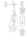
- FIG. 1 is a block diagram showing the configuration of a hybrid car including a regenerative brake control device according to an embodiment of the present invention.
- FIG. 2 is a block diagram showing functional components of the vehicle controller.
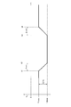
- FIG. 3 is a timing chart showing a state of transition between the first operation mode and the second operation mode in the embodiment of the present invention.
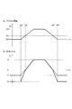
- FIG. 4 is a timing chart showing how the driver performs an accelerator operation in the second operation mode according to the embodiment of the present invention, wherein (a) is a change in accelerator opening, (b) is The state of change of command torque is shown.
- the configuration of a hybrid car including the regenerative brake control device according to the present embodiment will be described with reference to FIG.
- the hybrid car of the present embodiment includes an engine 1 (internal combustion engine), a generator 4 (electric motor), a battery 5, a drive motor 6 (drive source), and wheels 7 (drive wheels).
- the drive motor 6 drives the wheels 7 with the power from the battery 5 without driving the wheels 7 with the engine 1, and the engine 1, battery 5, drive motor 6 and wheels 7 are connected in series (series connection Because it is), it is called a series hybrid car.
- the engine 1 is mechanically coupled to the generator 4.
- the generator 4 is connected to the battery 5 so as to be capable of transmitting and receiving power. Power transmission and reception are also connected between the generator 4 and the drive motor 6, and between the battery 5 and the drive motor 6.
- the drive motor 6 is mechanically coupled to the axle via gears 16 and the axle is mechanically coupled to the wheel 7.
- the driving force of the engine 1 is transmitted to the generator 4, and the generator 4 is rotated by the driving force of the engine 1 to generate electric power.
- the power generated by the generator 4 flows to the battery 5
- the power is consumed to charge the battery 5.
- the power generated by the generator 4 flows to the drive motor 6, the power is consumed to drive the drive motor 6.
- the drive motor 6 receives supply of power from either or both of the generator 4 and the battery 5 and consumes the supplied power to generate drive power.
- the driving force of the drive motor 6 is transmitted to the wheel 7 via the gear 16 and the axle.
- the wheels 7 are rotated by the driving force of the drive motor 6, whereby the series hybrid car (hereinafter referred to as a vehicle) travels.
- the drive motor 6 operates as a generator to generate regenerative electric power.
- a regenerative braking force is generated on the wheel 7 via the gear 16 and the axle by the reaction of the torque input to the drive motor 6.
- the regenerative power generated by the drive motor 6 flows to the battery 5, the regenerative power is consumed to charge the battery 5. Further, when the regenerative electric power generated by the drive motor 6 flows to the generator 4, the regenerative electric power is consumed to drive the engine 1 and the generator 4 against the resistance (engine brake) of the engine 1 .
- the battery 5 has a function of charging and discharging. When the battery 5 is charged, the battery 5 stores energy of the power supplied from the generator 4 or the drive motor 6. When the battery 5 discharges, the battery 5 supplies the stored energy as electric power to the drive motor 6.
- the flow of power between the generator 4, the battery 5, and the drive motor 6 is determined by the state of the battery 5 and the drive motor 6, the traveling scene of the vehicle, and other accessories mounted on the vehicle (air conditioner, car stereo, etc. It may change based on the supply and demand condition of the electric power of the whole vehicle including a navigation system etc.).
- the flow of electric power between the generator 4, the battery 5, and the drive motor 6 is determined by the control of the vehicle controller 14 described later.
- the drive motor 6 when the drive motor 6 needs to generate a drive force, power may be supplied from the battery 5 to the drive motor 6.
- the engine 1 is driven to generate power by the generator 4, and in addition to the power from the battery 5, the power from the generator 4 is the drive motor 6 It may be supplied to
- the regenerative electric power generated by the drive motor 6 is supplied from the drive motor 6 to the battery 5 at the time of deceleration of the vehicle or when the vehicle goes down the slope. May be Furthermore, in a state where charging of the battery 5 is not completed, the engine 1 may be driven to generate electric power by the generator 4, and the electric power from the generator 4 may be supplied to the battery 5. .
- the vehicle selects a plurality of travel modes alternatively, a mode switch 17 (mode SW), a select lever 18 operated by a driver, a brake sensor 19 for detecting a braking force, and an accelerator position for detecting an accelerator opening. It further comprises a sensor 20 (APS) and a vehicle controller 14 which controls the entire hybrid car.
- the vehicle controller 14 functions as a control circuit that controls the electrically powered device according to the embodiment.
- the vehicle controller 14 is electrically connected to each of the mode switch 17, the select lever 18, the brake sensor 19, and the accelerator position sensor 20.
- the vehicle controller 14 receives a signal indicating the selected travel mode from the mode switch 17, receives a signal indicating the selected range from the select lever 18, and receives a signal indicating the brake hydraulic pressure from the brake sensor 19.
- a signal indicating the accelerator opening Ac of the accelerator pedal (input device) is received from the accelerator position sensor 20.
- the accelerator opening Ac has a value of 0 or more.
- the accelerator opening Ac in a state where the accelerator pedal is depressed and the driving force output from the drive motor 6 is zero is referred to as the neutral point of the accelerator opening Ac.
- the driving force output by the driving motor 6 has a negative value (braking force), and a regenerative braking force is generated.
- the accelerator opening Ac is larger than the neutral point, the driving force output by the driving motor 6 has a positive value.
- the range selectable by the select lever 18 includes, for example, a drive range (D), a brake range (B), a reverse range (R), a neutral range (N), a parking range (P) and the like.
- the drive range (D) and the brake range (B) are ranges used when moving the vehicle forward.
- the brake range (B) is a range in which a braking force stronger than the drive range (D) is generated when the accelerator is released (or when the accelerator opening Ac is smaller than the neutral point).
- the traveling modes selectable by the mode switch 17 include at least a first operation mode in which the driver manually controls the vehicle and a second operation mode in which the automatic control is performed.
- the automatic control performed in the second operation mode includes at least automatic adjustment of the speed and the inter-vehicle distance performed in the auto cruise.
- at least three drive modes of the eco mode, the sport mode, and the normal mode can be selected for each of the first drive mode and the second drive mode.
- the vehicle controller 14 is electrically connected to the engine 1, the generator 4, and the drive motor 6 through a signal line.
- the vehicle controller 14 controls the engine 1, the generator 4, and the drive motor 6 to cause the drive motor 6 to generate a vehicle driving force FD corresponding to the accelerator opening degree Ac.
- the vehicle controller 14 transmits the command torque Tc to the drive motor 6.
- the vehicle controller 14 controls the driving states of the engine 1, the generator 4 and the drive motor 6, and the state of the auxiliary equipment (not shown) is determined in addition to the power of the generator 4, the battery 5 and the drive motor 6. The flow is settled.
- the vehicle controller 14 can be realized by, for example, a general-purpose microcomputer including a CPU (central processing unit), a memory, and an input / output unit.
- a computer program (control program) for causing the microcomputer to function as the vehicle controller 14 is installed in the microcomputer and executed.
- the general-purpose microcomputer functions as the vehicle controller 14.
- the vehicle controller 14 may be configured by preparing dedicated hardware for executing each information processing described below. It is possible.
- the plurality of units (31, 33, 35, 37, 39) included in the vehicle controller 14 may be configured by individual hardware.
- the vehicle controller 14 may be shared with an electronic control unit (ECU) used for other control related to the vehicle.
- ECU electronice control unit
- the functional components of the vehicle controller 14 will be described with reference to FIG.
- the vehicle controller 14 includes, as functional components, a drive mode determination unit 35, a regenerative deceleration upper limit setting unit 37, a driving force coefficient calculation unit 39, a request value determination unit 31, and a command value determination unit 33. Equipped with
- the drive mode determination unit 35 determines which of the drive modes, the first drive mode and the second drive mode, is selected by the driver. Then, the drive mode determination unit 35 further determines which drive mode, the eco mode, the sport mode, or the normal mode, is selected by the driver.
- the operation mode determination unit 35 does not depend on the signal received from the mode switch 17, and any drive mode of the eco mode, the sport mode, and the normal mode It may be determined whether is selected by automatic control.
- the operation mode determination unit 35 determines the selected range.
- the regenerative deceleration upper limit setting unit 37 sets the upper limit value of the regenerative deceleration by the regenerative braking force (absolute value of the lower limit value of the drive force of the drive motor 6 based on the travel mode determined by the drive mode determination unit 35 and the range. Set the value) Specifically, when it is determined that the selected traveling mode is the first driving mode, the regenerative deceleration upper limit setting unit 37 sets the upper limit value of the regenerative deceleration based on Table 1.
- G means gravitational acceleration (standard gravity)
- 1G 9.80665 m / s 2 .
- D range represents a drive range
- B range represents a brake range.
- the B range is regarded as a range in which a braking force stronger than the D range is generated when the accelerator opening Ac is small. Therefore, when the first operation mode is selected, the normal range is normal.
- the upper limit value of the regenerative deceleration by the regenerative braking force in the mode and the B range is 0.12 G. This value is set larger than 0.06 G which is the upper limit value of the regenerative deceleration by the regenerative braking force in the normal mode and the D range.
- the regenerative deceleration upper limit setting unit 37 sets the upper limit value of the regenerative deceleration based on Table 2.
- the upper limit value of the regenerative deceleration when the drive mode is the normal mode and the range is the drive range Has been changed from 0.06G to 0.12G.
- the first upper limit (0.06 G in the above) of the first operation mode based on the regenerative braking force is smaller than the second upper limit (0.12 G in the above) of the second operation mode.
- the second upper limit value of the second operation mode is larger than the first upper limit value of the first operation mode, a stronger regenerative braking force is used in the second operation mode than in the first operation mode. be able to. As a result, since more kinetic energy of the vehicle can be recovered by the regenerative braking force, energy efficiency can be improved.
- a common value (0.12 G in the above) is set as the upper limit value of the regenerative deceleration for any drive mode. Further, in the second operation mode, a common value (0.12 G in the above) is set as the upper limit value of the regenerative deceleration for both the D range and the B range.
- the second upper limit value of the second operating mode is described as 0.12 G, but the control acceleration corresponding to the maximum value of the regenerative braking force that can be generated by the drive motor 6 is set to the second operating mode second
- the upper limit value may be used.
- the required value determination unit 31 determines a required torque Tm (required torque Tm by manual control) generated by the drive motor 6 based on the accelerator opening Ac received from the accelerator position sensor 20.
- the required value determination unit 31 determines the required torque Tma (required torque Tma by automatic control) generated by the drive motor 6 based on the automatic control.
- the driving force coefficient calculation unit 39 calculates the ratio of the required torque Tm by manual control and the required torque Tma by automatic control when the accelerator pedal is depressed in a situation where the second operation mode is selected. More specifically, the second upper limit of the second operation mode is divided by the first upper limit of the first operation mode at a timing when the accelerator pedal is depressed and the accelerator opening Ac starts to increase from 0, and division is performed. Is calculated as a driving force coefficient Cf. Further, the driving force coefficient calculation unit 39 calculates a value obtained by multiplying the driving force coefficient Cf by the manual control to the required torque Tm as the override upper limit acceleration Tmmd.
- the command value determination unit 33 actually determines the command torque Tc for the drive motor 6. More specifically, when the first operation mode is selected, the command value determination unit 33 sets the required torque Tm by manual control as the command torque Tc.
- the demand torque Tma by the automatic control is set as the command torque Tc.
- the required torque Tm by manual control
- the command torque Tc is determined based on the required torque Tma by control, the driving force coefficient Cf, and the override upper limit acceleration Tmmd.
- the command value determination unit 33 determines the required torque Tm by manual control.
- the command torque is Tc.
- the required torque Tm by manual control is less than 0 (when the accelerator opening Ac is smaller than the neutral point)
- the larger one of the override upper limit acceleration Tmmd and the required torque Tma by automatic control is command torque Tc.
- the required torque Tm by manual control is less than 0, the larger one of the override upper limit acceleration Tmmd and the required torque Tma by automatic control is used as the command torque Tc, so the required torque Tm by manual control is negative.
- the command torque Tc is also guaranteed to continuously change from a negative value to a positive value, as the value of V changes continuously from a positive value to a positive value.
- command torque Tc also changes continuously from the positive value to the negative value as the required torque Tm by manual control changes continuously from the positive value to the negative value.
- the vehicle controller 14 controls the drive motor 6 based on the command torque Tc for the drive motor 6 determined as described above. In addition, when regenerative electric power is generated by the drive motor 6, the vehicle controller 14 causes the generator 4 to forcibly discharge the generated regenerative electric power by the generator 4 or charge the battery 5. The battery 5 is controlled.
- the drive motor In addition to the regenerative braking force by 6, the braking force exceeding the upper limit value of the regenerative deceleration is realized using a friction brake (not shown).
- the first operation mode is selected for the period before time t1 and the period after time t4, and the second operation mode is selected for the period from time t2 to time t3.
- a period from time t1 to time t2 is a period for transition from the first operation mode to the second operation mode
- a period from time t3 to time t4 is a period for transition from the second operation mode to the first operation mode.
- the time length of the period from time t1 to time t2 be ⁇ ts1
- the accelerator opening Ac is 0, the required torque Tm by manual control is the minimum value T1 min, and the required torque Tma by automatic control is the minimum. It is assumed that the value is T2min. That is, in the first operation mode and the second operation mode, it is assumed that the drive motor 6 generates the maximum regenerative braking force. Such a case corresponds to, for example, a situation where the manual control is switched to the automatic control or the automatic control is switched to the manual control under a situation where the vehicle is going down a slope.
- the upper limit value of the regenerative deceleration increases, and the command torque Tc changes from T1 min to T2 min.
- the magnitude of the change in regenerative deceleration is ⁇ As.
- ⁇ As is shown without particularly distinguishing between the command torque Tc and the regenerative deceleration.
- the difference .DELTA.As between the first upper limit (corresponding to .vertline.T1min.vertline.) Of the first operation mode and the second upper limit (corresponding to .vertline.T2min.vertline.) Of the second operation mode should be equal to or less than a predetermined value. Is desirable.
- the rate of change ⁇ As / ⁇ ts1 of the upper limit value of the regenerative deceleration is set to be approximately 0 to 0.1 G / s. More specifically, it is desirable that the rate of change ⁇ As / ⁇ ts1 of the upper limit value of the regenerative deceleration not exceed a value of 0.08 G / s.
- the upper limit value of the regenerative deceleration decreases, and the command torque Tc changes from T2 min to T1 min.
- the rate of change ⁇ As / ⁇ ts2 of the upper limit value of the regenerative deceleration be set to be approximately 0 to 0.1 G / s. More specifically, it is desirable that the rate of change ⁇ As / ⁇ ts2 of the upper limit value of the regenerative deceleration not exceed a value of 0.08 G / s.
- the rate of change of the upper limit value of the regenerative deceleration be within a predetermined range in a transition period between the first operation mode and the second operation mode. As a result, it is possible to reduce a sense of discomfort felt by the occupant of the vehicle in a transition period of the traveling mode.
- the accelerator opening Ac is 0, the required torque Tm by manual control is the minimum value T1 min, and the required torque Tma by the automatic control is the minimum value T2 min.
- the present embodiment is applicable not only to such a situation, but also to the case where the required torque Tm by manual control fluctuates or the required torque Tma by automatic control fluctuates when the accelerator pedal is depressed.
- FIG. 4A shows the change of the accelerator opening
- FIG. 4B shows the change of the command torque for the drive motor 6.
- values T1 and T2 respectively indicate the lower limit value of the required torque Tm (dotted line) by manual control and the lower limit value of the required torque Tma (solid line) by automatic control. That is,
- the period from time ta1 to time ta2 is a period in which the accelerator opening Ac has a value equal to or less than the neutral point Ac1, and at time ta2, the accelerator opening Ac is the neutral point Ac1.
- the period from time ta5 to time ta6 is a period in which the accelerator opening Ac has a value equal to or less than the neutral point Ac1, and at time ta5, the accelerator opening Ac is the neutral point Ac1.
- the accelerator opening Ac has a value equal to or greater than the neutral point Ac1.
- accelerator override When the driver of the vehicle depresses the accelerator pedal while the second operation mode is selected and automatic control is being executed, control based on the operation of the accelerator pedal by the driver is given priority over automatic control. I do.
- accelerator override Such driving force control by the driver under the second driving mode is referred to as accelerator override.
- the command torque Tc changes discontinuously There is a possibility that the driver may feel discomfort through the driving force of the vehicle.
- the command value is set such that a continuous change in command torque Tc as shown in FIG. 4B occurs in accordance with the change in accelerator opening Ac as shown in FIG. 4A.
- the determination unit 33 adjusts the command torque Tc.
- the command value determination unit 33 sets the required torque Tm by manual control as the command torque Tc.
- the command torque Tc is changed at a rate of change greater than the rate of change of the required torque Tm by manual control calculated based on the accelerator opening Ac.
- ) at time ta1 is divided by the first upper limit (
- a value obtained by multiplying the required torque Tm by manual control by the driving force coefficient Cf is the override upper limit acceleration Tmmd, and the larger one of the demand torque Tma by automatic control and the override upper limit acceleration Tmmd (when both are equal Sets the required torque Tma) as the command torque Tc.
- the command torque Tc changes continuously before and after time ta2 because the larger of torque required by automatic control Tma and override upper limit acceleration Tmmd is used as command torque Tc in the period from time ta1 to time ta2 Guaranteed.
- the command torque Tc changes continuously before and after time ta5 because the larger one of the required torque Tma by automatic control and the override upper limit acceleration Tmmd is used as the command torque Tc. Is guaranteed.
- the regenerative brake control method and the regenerative brake control device switches between the first operation mode in which the driver performs manual control and the second operation mode in which the automatic control is performed.
- a first upper limit value of regenerative deceleration in the first operating mode by the regenerative braking force is in the second operating mode It is smaller than the 2nd upper limit of regenerative deceleration.
- a regenerative braking force that is stronger than that in the first operation mode can be used.
- the first upper limit value of the regenerative deceleration in the first operation mode by the regenerative braking force is smaller than the second upper limit value of the regenerative deceleration in the second operation mode, the maximum deceleration during manual control can be suppressed small. Therefore, even when the accelerator pedal is released and the accelerator opening Ac is small, the braking force is suppressed, and smooth driving can be realized.
- the difference between the second upper limit value and the second upper limit value may be equal to or less than a predetermined value.
- the change rate of the upper limit value of the regenerative deceleration at the time of transition between the first operation mode and the second operation mode falls within a predetermined range. It may be one. Thereby, the change of the vehicle driving force at the time of transitioning between the first driving mode and the second driving mode can be realized smoothly, and the uncomfortable feeling of the vehicle occupant can be reduced.
- the second upper limit may be set to the maximum value of the regenerative braking force that can be generated by the drive motor 6.
- the regenerative braking force that can be generated by the drive motor 6 can be utilized to the fullest, and the possibility of recovering the kinetic energy of the vehicle in automatic control can be obtained, so that energy efficiency can be improved.
- the first driving mode is performed based on the command value received from the driver via the input device through which the driver inputs the request for acceleration and deceleration. It is also possible to calculate the regenerative deceleration in
- the input device may be an accelerator pedal.
- the maximum value of the values that can be input to the input device is associated with the maximum value of the driving force of the drive motor 6, and the minimum value of the values that can be input to the input device is associated with the minimum value of the driving force of the drive motor 6,
- the upper limit value smaller than the second upper limit value, it is possible to reduce the change in the driving force of the drive motor 6 per unit change amount of the value that can be input to the input device.
- the driver can easily operate the input device in accordance with the target value of the vehicle driving force. Then, undershoot / overshoot with respect to the target value of the vehicle driving force is less likely to occur, and the driving operability of the vehicle is improved.
- the regenerative deceleration in the first driving mode is determined based on the command value received from the driver via the input device
- the regenerative deceleration in the second driving mode is determined based on the automatic control.
- the regenerative deceleration in the second operation mode is accurately determined in accordance with the target value of the vehicle driving force, so that the problem of undershoot / overshooting the target value of the vehicle driving force does not occur.
- the required torque Tm first required acceleration
- the required torque Tm is taken as the command torque Tc
- the required torque Tm is less than 0
- the command torque Tc may be changed at a rate of change greater than the rate of change of the required torque Tm.
- the second upper limit at the timing when the driving force instruction is started is the first upper limit at the timing
- the value obtained by dividing by is calculated as the driving force coefficient Cf (predetermined coefficient)
- the value obtained by multiplying the driving force coefficient Cf by the required torque Tm is the override upper limit acceleration Tmmd
- the required torque Tma by automatic control The larger one of (the second required acceleration) and the override upper limit acceleration Tmmd may be used as the command torque Tc.
- a braking force (requested braking force) or a braking force exceeding the upper limit value (first upper limit value and second upper limit value) of the regenerative deceleration.
- a friction brake is used to realize a braking force exceeding the upper limit value of the regenerative deceleration.
- the transmission gear ratio may change depending on mode selection such as range selection and driving conditions (manual control / automatic control).
- mode selection such as range selection and driving conditions (manual control / automatic control).
- the mode is selected, the number of revolutions of the engine changes, so that the noise felt by the occupant may change. Therefore, in order to reduce the sense of incongruity felt by the occupants, it is almost always the case that the change in sound is reduced before and after the selection of the mode or the driving state in the engine-driven vehicle, and the upper limit of deceleration is changed. There is no.
- the engine is not directly connected to the axle, and the motor instead of the engine Rotates the axle.
- the motor has a characteristic that the variable region of the torque and rotational speed of the output shaft of the motor is wider than that of the engine. Therefore, even when the gear ratio of the gear 16 interposed between the motor and the axle is fixed, it is possible to drive the axle sufficiently. As a result, when the mode is selected, the change in the number of revolutions of the electric motor causes a small change in the sound felt by the occupant.
- the processing circuitry comprises a programmed processing device, such as a processing device that includes an electrical circuit.
- the processing device also includes devices such as application specific integrated circuits (ASICs) and conventional circuit components arranged to perform the functions described in the embodiments.
- ASICs application specific integrated circuits
Landscapes
- Engineering & Computer Science (AREA)
- Mechanical Engineering (AREA)
- Transportation (AREA)
- Power Engineering (AREA)
- Chemical & Material Sciences (AREA)
- Combustion & Propulsion (AREA)
- Life Sciences & Earth Sciences (AREA)
- Sustainable Development (AREA)
- Sustainable Energy (AREA)
- General Engineering & Computer Science (AREA)
- Electromagnetism (AREA)
- Automation & Control Theory (AREA)
- Physics & Mathematics (AREA)
- Electric Propulsion And Braking For Vehicles (AREA)
- Regulating Braking Force (AREA)
- Stopping Of Electric Motors (AREA)
Abstract
Description
図1を参照して、本実施形態に係わる回生ブレーキ制御装置を含むハイブリッドカーの構成を説明する。本実施形態のハイブリッドカーは、エンジン1(内燃機関)と、発電機4(電動機)と、バッテリ5と、駆動モータ6(駆動源)と、車輪7(駆動輪)と、を備える。ハイブリッドカーは、エンジン1で車輪7を駆動せず、バッテリ5からの電力で駆動モータ6が車輪7を駆動するもので、エンジン1、バッテリ5、駆動モータ6、車輪7が直列接続(シリーズ接続)されることから、シリーズハイブリッドカーと称される。


次に、本実施形態における、第1運転モードと第2運転モードの間での遷移の様子を、図3のタイミングチャートを参照して説明する。
次に、本実施形態における、第2運転モードにおいて運転者によるアクセル操作が行われた際の様子を、図4(a)および図4(b)のタイミングチャートを参照して説明する。図4(a)はアクセル開度の変化、図4(b)は駆動モータ6に対する指令トルクの変化の様子を示す。
以上詳細に説明したように、本実施形態に係る回生ブレーキ制御方法及び回生ブレーキ制御装置は、運転者が手動制御を行う第1運転モードと自動制御が行われる第2運転モードとの間で切り替え可能な車両に搭載された、回生制動力を生じさせる駆動モータ6(駆動源)を制御する際、回生制動力による第1運転モードにおける回生減速度の第1上限値が、第2運転モードにおける回生減速度の第2上限値よりも小さい。これにより、第2運転モードにおいて、第1運転モードの場合よりも強い回生制動力を利用することができる。
4 発電機
5 バッテリ
6 駆動モータ
7 車輪
14 車両コントローラ
16 ギア
17 モードスイッチ
18 セレクトレバー
19 ブレーキセンサ
20 アクセルポジションセンサ
31 要求値決定部
33 指令値決定部
35 運転モード判定部
37 回生減速度上限設定部
39 駆動力係数算出部
Claims (11)
- 運転者が手動制御を行う第1運転モードと自動制御が行われる第2運転モードとの間で切り替え可能な車両に搭載された、回生制動力を生じさせる駆動源
を制御する回生ブレーキ制御方法であって、
前記回生制動力による前記第1運転モードにおける回生減速度の第1上限値が、前記第2運転モードにおける前記回生減速度の第2上限値よりも小さいこと
を特徴とする回生ブレーキ制御方法。 - 請求項1に記載の回生ブレーキ制御方法であって、
前記第1上限値と前記第2上限値の間の差が、所定値以下であること
を特徴とする回生ブレーキ制御方法。 - 請求項1又は2に記載の回生ブレーキ制御方法であって、
前記第1運転モードと前記第2運転モードの間で遷移する際の前記回生減速度の上限値の変化率が、所定範囲内に収まること
を特徴とする回生ブレーキ制御方法。 - 請求項1~3のいずれか一項に記載の回生ブレーキ制御方法であって、
前記第2上限値は、前記駆動源によって発生可能な前記回生制動力の最大値であること
を特徴とする回生ブレーキ制御方法。 - 請求項1~4のいずれか一項に記載の回生ブレーキ制御方法であって、
前記運転者が加速度および減速度の要求を入力する入力装置を介して前記運転者から受け付けた指令値に基づいて、前記第1運転モードにおける前記回生減速度が算出されること
を特徴とする回生ブレーキ制御方法。 - 請求項5に記載の回生ブレーキ制御方法であって、
前記入力装置はアクセルペダルであること
を特徴とする回生ブレーキ制御方法。 - 請求項1~6のいずれか一項に記載の回生ブレーキ制御方法であって、
前記第2運転モードにおいて、
前記運転者の駆動力指示に基づいて第1要求加速度を算出し、
前記第1要求加速度が0以上である場合には、前記第1要求加速度を前記駆動源に出力する駆動力指令値とし、
前記第1要求加速度が0未満である場合には、前記第1要求加速度の変化率よりも大きな変化率で前記駆動力指令値を変化させること
を特徴とする回生ブレーキ制御方法。 - 請求項7に記載の回生ブレーキ制御方法であって、
前記第1要求加速度が0未満である場合には、
前記駆動力指示が開始されたタイミングにおける前記第2上限値を前記タイミングにおける前記第1上限値で除算して得られる値を所定係数として算出し、
前記所定係数を前記第1要求加速度に乗算して得られる値をオーバーライド上限加速度とし、前記自動制御に基づく第2要求加速度と前記オーバーライド上限加速度のうち大きい方の値を前記駆動力指令値とすること
を特徴とする回生ブレーキ制御方法。 - 請求項1~8のいずれか一項に記載の回生ブレーキ制御方法であって、
前記第1運転モードにおいて、要求された減速度が前記第1上限値を上回る場合には、前記駆動源と前記車両に搭載された摩擦ブレーキを使用して、前記減速度を発生させること
を特徴とする回生ブレーキ制御方法。 - 請求項1~9のいずれか一項に記載の回生ブレーキ制御方法であって、
前記第2運転モードにおいて、要求された減速度が前記第2上限値を上回る場合には、前記駆動源と前記車両に搭載された摩擦ブレーキを使用して、前記減速度を発生させること
を特徴とする回生ブレーキ制御方法。 - 運転者が手動制御を行う第1運転モードと自動制御が行われる第2運転モードとの間で切り替え可能な車両に搭載された、回生制動力を生じさせる駆動源
を制御する制御回路を備える回生ブレーキ制御装置であって、
前記回生制動力による前記第1運転モードにおける回生減速度の第1上限値が、前記第2運転モードにおける前記回生減速度の第2上限値よりも小さいこと
を特徴とする回生ブレーキ制御装置。
Priority Applications (9)
| Application Number | Priority Date | Filing Date | Title |
|---|---|---|---|
| CN201780097653.8A CN111542452B (zh) | 2017-12-15 | 2017-12-15 | 再生制动控制方法和再生制动控制装置 |
| EP17934365.2A EP3725581A4 (en) | 2017-12-15 | 2017-12-15 | RECOVERY BRAKE CONTROL PROCESS AND RECOVERY BRAKE CONTROL DEVICE |
| BR112020011819-2A BR112020011819B1 (pt) | 2017-12-15 | Método de controle da frenagem regenerativa e dispositivo de controle da frenagem regenerativa | |
| PCT/JP2017/045164 WO2019116553A1 (ja) | 2017-12-15 | 2017-12-15 | 回生ブレーキ制御方法及び回生ブレーキ制御装置 |
| MX2020006159A MX2020006159A (es) | 2017-12-15 | 2017-12-15 | Metodo de control de frenado regenerativo y dispositivo de control de frenado regenerativo. |
| US16/771,018 US11505071B2 (en) | 2017-12-15 | 2017-12-15 | Regenerative braking control method and regenerative braking control device |
| RU2020121838A RU2750051C1 (ru) | 2017-12-15 | 2017-12-15 | Способ управления рекуперативным торможением и устройство управления рекуперативным торможением |
| JP2019558843A JP6915696B2 (ja) | 2017-12-15 | 2017-12-15 | 回生ブレーキ制御方法及び回生ブレーキ制御装置 |
| KR1020207016772A KR102296463B1 (ko) | 2017-12-15 | 2017-12-15 | 회생 브레이크 제어 방법 및 회생 브레이크 제어 장치 |
Applications Claiming Priority (1)
| Application Number | Priority Date | Filing Date | Title |
|---|---|---|---|
| PCT/JP2017/045164 WO2019116553A1 (ja) | 2017-12-15 | 2017-12-15 | 回生ブレーキ制御方法及び回生ブレーキ制御装置 |
Publications (1)
| Publication Number | Publication Date |
|---|---|
| WO2019116553A1 true WO2019116553A1 (ja) | 2019-06-20 |
Family
ID=66820144
Family Applications (1)
| Application Number | Title | Priority Date | Filing Date |
|---|---|---|---|
| PCT/JP2017/045164 Ceased WO2019116553A1 (ja) | 2017-12-15 | 2017-12-15 | 回生ブレーキ制御方法及び回生ブレーキ制御装置 |
Country Status (8)
| Country | Link |
|---|---|
| US (1) | US11505071B2 (ja) |
| EP (1) | EP3725581A4 (ja) |
| JP (1) | JP6915696B2 (ja) |
| KR (1) | KR102296463B1 (ja) |
| CN (1) | CN111542452B (ja) |
| MX (1) | MX2020006159A (ja) |
| RU (1) | RU2750051C1 (ja) |
| WO (1) | WO2019116553A1 (ja) |
Cited By (3)
| Publication number | Priority date | Publication date | Assignee | Title |
|---|---|---|---|---|
| JP2021191153A (ja) * | 2020-06-02 | 2021-12-13 | 株式会社Subaru | 車両制御装置 |
| JP2022150612A (ja) * | 2021-03-26 | 2022-10-07 | 株式会社Subaru | 制御装置 |
| JP2023180533A (ja) * | 2022-06-09 | 2023-12-21 | トヨタ自動車株式会社 | 車両の減速制御装置 |
Families Citing this family (9)
| Publication number | Priority date | Publication date | Assignee | Title |
|---|---|---|---|---|
| JP6826793B2 (ja) * | 2018-09-28 | 2021-02-10 | 本田技研工業株式会社 | 制御装置、制御方法及びプログラム |
| JP7414537B2 (ja) * | 2020-01-14 | 2024-01-16 | 日立Astemo株式会社 | 電動車両の制御装置、電動車両の制御方法および電動車両の制御システム |
| US11745600B2 (en) * | 2020-02-04 | 2023-09-05 | Subaru Corporation | Driving force controller for vehicle |
| WO2022024770A1 (ja) * | 2020-07-31 | 2022-02-03 | 三菱自動車工業株式会社 | 車両の走行制御装置 |
| KR102327664B1 (ko) * | 2020-12-31 | 2021-11-18 | (주)제인모터스 | 전기차(xEV)의 강제 제어 시스템 |
| CN114274956A (zh) * | 2021-12-28 | 2022-04-05 | 上海集度汽车有限公司 | 车辆巡航控制方法、装置、车辆及可读存储介质 |
| EP4375154B1 (en) * | 2022-11-23 | 2026-03-18 | Volvo Truck Corporation | Controlling acceleration of a vehicle using auxiliary brakes |
| CN120513180A (zh) * | 2022-12-20 | 2025-08-19 | 万国引擎知识产权有限责任公司 | 功率管理系统和方法 |
| DE102023120572A1 (de) * | 2023-08-03 | 2025-02-06 | Audi Aktiengesellschaft | Verfahren zum Betreiben eines Kraftfahrzeugs sowie entsprechendes Kraftfahrzeug |
Citations (3)
| Publication number | Priority date | Publication date | Assignee | Title |
|---|---|---|---|---|
| JP2015029416A (ja) | 2014-09-24 | 2015-02-12 | 三菱自動車工業株式会社 | 回生ブレーキ制御装置 |
| JP2016111760A (ja) * | 2014-12-03 | 2016-06-20 | 日産自動車株式会社 | 制駆動力制御装置及び制駆動力制御方法 |
| JP2017208898A (ja) * | 2016-05-17 | 2017-11-24 | 株式会社Soken | 電動車両 |
Family Cites Families (17)
| Publication number | Priority date | Publication date | Assignee | Title |
|---|---|---|---|---|
| JP3307269B2 (ja) * | 1997-04-25 | 2002-07-24 | トヨタ自動車株式会社 | 電気自動車のモータ制御装置 |
| JP3698014B2 (ja) * | 2000-05-16 | 2005-09-21 | 日産自動車株式会社 | 車速制御装置 |
| US7311163B2 (en) * | 2004-11-16 | 2007-12-25 | Eaton Corporation | Regeneration and brake management system |
| FR2923422B1 (fr) * | 2007-11-14 | 2010-05-14 | Renault Sas | Procede de controle du freinage recuperatif d'un vehicule comprenant au moins un moteur electrique |
| US8738260B2 (en) * | 2009-08-07 | 2014-05-27 | Toyota Jidosha Kabushiki Kaisha | Brake control system, and brake control method |
| JP5414454B2 (ja) * | 2009-10-23 | 2014-02-12 | 日立オートモティブシステムズ株式会社 | 車両運動制御装置 |
| JP5652118B2 (ja) * | 2010-10-22 | 2015-01-14 | 日産自動車株式会社 | 車両用走行制御装置及び車両用走行制御方法 |
| KR101454249B1 (ko) * | 2012-02-06 | 2014-11-03 | 엘지전자 주식회사 | 차량의 회생 제동 장치 및 그 방법 |
| JP5790870B2 (ja) * | 2012-03-14 | 2015-10-07 | 日産自動車株式会社 | 制動制御装置及び制御方法 |
| JP5896301B2 (ja) * | 2012-12-25 | 2016-03-30 | 三菱自動車工業株式会社 | 回生ブレーキ制御装置 |
| JP5811148B2 (ja) * | 2013-07-11 | 2015-11-11 | トヨタ自動車株式会社 | 回生発電機付車両 |
| JP6171743B2 (ja) * | 2013-09-03 | 2017-08-02 | マツダ株式会社 | 車両の走行制御装置 |
| JP5810232B1 (ja) * | 2014-03-28 | 2015-11-11 | 富士重工業株式会社 | 車両用制御装置 |
| JP6318950B2 (ja) * | 2014-07-29 | 2018-05-09 | トヨタ自動車株式会社 | 車両の制御装置 |
| US9827955B2 (en) * | 2015-03-06 | 2017-11-28 | Ford Global Technologies, Llc | Systems and methods to improve fuel economy using adaptive cruise in a hybrid electric vehicle when approaching traffic lights |
| JP6304193B2 (ja) | 2015-10-22 | 2018-04-04 | トヨタ自動車株式会社 | 車両制御装置 |
| US10150371B2 (en) * | 2016-11-03 | 2018-12-11 | Ford Global Technologies,Llc | Regenerative braking method |
-
2017
- 2017-12-15 RU RU2020121838A patent/RU2750051C1/ru active
- 2017-12-15 WO PCT/JP2017/045164 patent/WO2019116553A1/ja not_active Ceased
- 2017-12-15 EP EP17934365.2A patent/EP3725581A4/en active Pending
- 2017-12-15 KR KR1020207016772A patent/KR102296463B1/ko active Active
- 2017-12-15 MX MX2020006159A patent/MX2020006159A/es unknown
- 2017-12-15 US US16/771,018 patent/US11505071B2/en active Active
- 2017-12-15 JP JP2019558843A patent/JP6915696B2/ja active Active
- 2017-12-15 CN CN201780097653.8A patent/CN111542452B/zh active Active
Patent Citations (3)
| Publication number | Priority date | Publication date | Assignee | Title |
|---|---|---|---|---|
| JP2015029416A (ja) | 2014-09-24 | 2015-02-12 | 三菱自動車工業株式会社 | 回生ブレーキ制御装置 |
| JP2016111760A (ja) * | 2014-12-03 | 2016-06-20 | 日産自動車株式会社 | 制駆動力制御装置及び制駆動力制御方法 |
| JP2017208898A (ja) * | 2016-05-17 | 2017-11-24 | 株式会社Soken | 電動車両 |
Non-Patent Citations (1)
| Title |
|---|
| See also references of EP3725581A4 |
Cited By (6)
| Publication number | Priority date | Publication date | Assignee | Title |
|---|---|---|---|---|
| JP2021191153A (ja) * | 2020-06-02 | 2021-12-13 | 株式会社Subaru | 車両制御装置 |
| JP7525303B2 (ja) | 2020-06-02 | 2024-07-30 | 株式会社Subaru | 車両制御装置 |
| JP2022150612A (ja) * | 2021-03-26 | 2022-10-07 | 株式会社Subaru | 制御装置 |
| JP7698445B2 (ja) | 2021-03-26 | 2025-06-25 | 株式会社Subaru | 制御装置 |
| JP2023180533A (ja) * | 2022-06-09 | 2023-12-21 | トヨタ自動車株式会社 | 車両の減速制御装置 |
| JP7694468B2 (ja) | 2022-06-09 | 2025-06-18 | トヨタ自動車株式会社 | 車両の減速制御装置 |
Also Published As
| Publication number | Publication date |
|---|---|
| BR112020011819A2 (pt) | 2020-11-17 |
| CN111542452B (zh) | 2023-08-08 |
| RU2750051C1 (ru) | 2021-06-21 |
| KR102296463B1 (ko) | 2021-09-02 |
| JP6915696B2 (ja) | 2021-08-04 |
| CN111542452A (zh) | 2020-08-14 |
| EP3725581A1 (en) | 2020-10-21 |
| MX2020006159A (es) | 2020-08-13 |
| JPWO2019116553A1 (ja) | 2021-02-25 |
| US20210162869A1 (en) | 2021-06-03 |
| KR20200084894A (ko) | 2020-07-13 |
| EP3725581A4 (en) | 2020-12-23 |
| US11505071B2 (en) | 2022-11-22 |
Similar Documents
| Publication | Publication Date | Title |
|---|---|---|
| JP6915696B2 (ja) | 回生ブレーキ制御方法及び回生ブレーキ制御装置 | |
| JP7004007B2 (ja) | ハイブリッド車両の制御方法及び制御装置 | |
| US10377242B2 (en) | Regenerative brake control device | |
| JP6553469B2 (ja) | 車両制御装置 | |
| CN111491839B (zh) | 混合动力车辆的控制方法和控制装置 | |
| JP7004006B2 (ja) | ハイブリッド車両の制御方法及び制御装置 | |
| WO2011152128A1 (ja) | 車両用電動モータのトルク応答制御装置 | |
| JP6501069B2 (ja) | 車両の回生制御装置 | |
| JP2019196794A (ja) | 車両の変速制御装置 | |
| US8628450B2 (en) | Vehicular power transmission control apparatus | |
| JP2005263098A (ja) | オートクルーズ制御装置 | |
| CN114286768B (zh) | 串联混合动力车辆的控制方法以及串联混合动力车辆 | |
| KR102270995B1 (ko) | 전동 장치 제어 방법 및 전동 장치 | |
| JP2020033884A (ja) | 車両の制御方法及び制御装置 | |
| JP7404803B2 (ja) | 変速制御装置 | |
| CN110691725B (zh) | 用于推进车辆的方法和系统 | |
| JP2005269793A (ja) | ハイブリッド車両 | |
| JP4236239B2 (ja) | 車両の補機への供給電力制御装置 | |
| US20240326602A1 (en) | Method of implementing engine braking using a virtual gear shift system of an electric vehicle | |
| JP2013135483A (ja) | 車両の制動力制御装置 | |
| JP3894049B2 (ja) | ハイブリッド車両とその制御装置 | |
| JP2025047644A (ja) | 電動車両の駆動力制御装置 | |
| JP2021097513A (ja) | 車両の制御装置 | |
| JP2022049731A (ja) | ハイブリッド駆動装置 | |
| JP2014236636A (ja) | 車両用回生制御装置 |
Legal Events
| Date | Code | Title | Description |
|---|---|---|---|
| 121 | Ep: the epo has been informed by wipo that ep was designated in this application |
Ref document number: 17934365 Country of ref document: EP Kind code of ref document: A1 |
|
| ENP | Entry into the national phase |
Ref document number: 2019558843 Country of ref document: JP Kind code of ref document: A |
|
| ENP | Entry into the national phase |
Ref document number: 20207016772 Country of ref document: KR Kind code of ref document: A |
|
| NENP | Non-entry into the national phase |
Ref country code: DE |
|
| ENP | Entry into the national phase |
Ref document number: 2017934365 Country of ref document: EP Effective date: 20200715 |
|
| REG | Reference to national code |
Ref country code: BR Ref legal event code: B01A Ref document number: 112020011819 Country of ref document: BR |
|
| ENP | Entry into the national phase |
Ref document number: 112020011819 Country of ref document: BR Kind code of ref document: A2 Effective date: 20200612 |