WO2019116576A1 - Procédé et dispositif de commande de véhicule hybride - Google Patents
Procédé et dispositif de commande de véhicule hybride Download PDFInfo
- Publication number
- WO2019116576A1 WO2019116576A1 PCT/JP2017/045210 JP2017045210W WO2019116576A1 WO 2019116576 A1 WO2019116576 A1 WO 2019116576A1 JP 2017045210 W JP2017045210 W JP 2017045210W WO 2019116576 A1 WO2019116576 A1 WO 2019116576A1
- Authority
- WO
- WIPO (PCT)
- Prior art keywords
- power
- battery
- upper limit
- mode
- limit value
- Prior art date
- Legal status (The legal status is an assumption and is not a legal conclusion. Google has not performed a legal analysis and makes no representation as to the accuracy of the status listed.)
- Ceased
Links
Images



Classifications
-
- B—PERFORMING OPERATIONS; TRANSPORTING
- B60—VEHICLES IN GENERAL
- B60W—CONJOINT CONTROL OF VEHICLE SUB-UNITS OF DIFFERENT TYPE OR DIFFERENT FUNCTION; CONTROL SYSTEMS SPECIALLY ADAPTED FOR HYBRID VEHICLES; ROAD VEHICLE DRIVE CONTROL SYSTEMS FOR PURPOSES NOT RELATED TO THE CONTROL OF A PARTICULAR SUB-UNIT
- B60W20/00—Control systems specially adapted for hybrid vehicles
- B60W20/10—Controlling the power contribution of each of the prime movers to meet required power demand
- B60W20/13—Controlling the power contribution of each of the prime movers to meet required power demand in order to stay within battery power input or output limits; in order to prevent overcharging or battery depletion
- B60W20/14—Controlling the power contribution of each of the prime movers to meet required power demand in order to stay within battery power input or output limits; in order to prevent overcharging or battery depletion in conjunction with braking regeneration
-
- B—PERFORMING OPERATIONS; TRANSPORTING
- B60—VEHICLES IN GENERAL
- B60K—ARRANGEMENT OR MOUNTING OF PROPULSION UNITS OR OF TRANSMISSIONS IN VEHICLES; ARRANGEMENT OR MOUNTING OF PLURAL DIVERSE PRIME-MOVERS IN VEHICLES; AUXILIARY DRIVES FOR VEHICLES; INSTRUMENTATION OR DASHBOARDS FOR VEHICLES; ARRANGEMENTS IN CONNECTION WITH COOLING, AIR INTAKE, GAS EXHAUST OR FUEL SUPPLY OF PROPULSION UNITS IN VEHICLES
- B60K6/00—Arrangement or mounting of plural diverse prime-movers for mutual or common propulsion, e.g. hybrid propulsion systems comprising electric motors and internal combustion engines
- B60K6/20—Arrangement or mounting of plural diverse prime-movers for mutual or common propulsion, e.g. hybrid propulsion systems comprising electric motors and internal combustion engines the prime-movers consisting of electric motors and internal combustion engines, e.g. HEVs
- B60K6/42—Arrangement or mounting of plural diverse prime-movers for mutual or common propulsion, e.g. hybrid propulsion systems comprising electric motors and internal combustion engines the prime-movers consisting of electric motors and internal combustion engines, e.g. HEVs characterised by the architecture of the hybrid electric vehicle
- B60K6/46—Series type
-
- B—PERFORMING OPERATIONS; TRANSPORTING
- B60—VEHICLES IN GENERAL
- B60W—CONJOINT CONTROL OF VEHICLE SUB-UNITS OF DIFFERENT TYPE OR DIFFERENT FUNCTION; CONTROL SYSTEMS SPECIALLY ADAPTED FOR HYBRID VEHICLES; ROAD VEHICLE DRIVE CONTROL SYSTEMS FOR PURPOSES NOT RELATED TO THE CONTROL OF A PARTICULAR SUB-UNIT
- B60W20/00—Control systems specially adapted for hybrid vehicles
- B60W20/10—Controlling the power contribution of each of the prime movers to meet required power demand
- B60W20/13—Controlling the power contribution of each of the prime movers to meet required power demand in order to stay within battery power input or output limits; in order to prevent overcharging or battery depletion
-
- B—PERFORMING OPERATIONS; TRANSPORTING
- B60—VEHICLES IN GENERAL
- B60K—ARRANGEMENT OR MOUNTING OF PROPULSION UNITS OR OF TRANSMISSIONS IN VEHICLES; ARRANGEMENT OR MOUNTING OF PLURAL DIVERSE PRIME-MOVERS IN VEHICLES; AUXILIARY DRIVES FOR VEHICLES; INSTRUMENTATION OR DASHBOARDS FOR VEHICLES; ARRANGEMENTS IN CONNECTION WITH COOLING, AIR INTAKE, GAS EXHAUST OR FUEL SUPPLY OF PROPULSION UNITS IN VEHICLES
- B60K6/00—Arrangement or mounting of plural diverse prime-movers for mutual or common propulsion, e.g. hybrid propulsion systems comprising electric motors and internal combustion engines
- B60K6/20—Arrangement or mounting of plural diverse prime-movers for mutual or common propulsion, e.g. hybrid propulsion systems comprising electric motors and internal combustion engines the prime-movers consisting of electric motors and internal combustion engines, e.g. HEVs
- B60K6/22—Arrangement or mounting of plural diverse prime-movers for mutual or common propulsion, e.g. hybrid propulsion systems comprising electric motors and internal combustion engines the prime-movers consisting of electric motors and internal combustion engines, e.g. HEVs characterised by apparatus, components or means specially adapted for HEVs
- B60K6/28—Arrangement or mounting of plural diverse prime-movers for mutual or common propulsion, e.g. hybrid propulsion systems comprising electric motors and internal combustion engines the prime-movers consisting of electric motors and internal combustion engines, e.g. HEVs characterised by apparatus, components or means specially adapted for HEVs characterised by the electric energy storing means, e.g. batteries or capacitors
-
- B—PERFORMING OPERATIONS; TRANSPORTING
- B60—VEHICLES IN GENERAL
- B60L—PROPULSION OF ELECTRICALLY-PROPELLED VEHICLES; SUPPLYING ELECTRIC POWER FOR AUXILIARY EQUIPMENT OF ELECTRICALLY-PROPELLED VEHICLES; ELECTRODYNAMIC BRAKE SYSTEMS FOR VEHICLES IN GENERAL; MAGNETIC SUSPENSION OR LEVITATION FOR VEHICLES; MONITORING OPERATING VARIABLES OF ELECTRICALLY-PROPELLED VEHICLES; ELECTRIC SAFETY DEVICES FOR ELECTRICALLY-PROPELLED VEHICLES
- B60L50/00—Electric propulsion with power supplied within the vehicle
- B60L50/50—Electric propulsion with power supplied within the vehicle using propulsion power supplied by batteries or fuel cells
- B60L50/60—Electric propulsion with power supplied within the vehicle using propulsion power supplied by batteries or fuel cells using power supplied by batteries
- B60L50/61—Electric propulsion with power supplied within the vehicle using propulsion power supplied by batteries or fuel cells using power supplied by batteries by batteries charged by engine-driven generators, e.g. series hybrid electric vehicles
-
- B—PERFORMING OPERATIONS; TRANSPORTING
- B60—VEHICLES IN GENERAL
- B60L—PROPULSION OF ELECTRICALLY-PROPELLED VEHICLES; SUPPLYING ELECTRIC POWER FOR AUXILIARY EQUIPMENT OF ELECTRICALLY-PROPELLED VEHICLES; ELECTRODYNAMIC BRAKE SYSTEMS FOR VEHICLES IN GENERAL; MAGNETIC SUSPENSION OR LEVITATION FOR VEHICLES; MONITORING OPERATING VARIABLES OF ELECTRICALLY-PROPELLED VEHICLES; ELECTRIC SAFETY DEVICES FOR ELECTRICALLY-PROPELLED VEHICLES
- B60L58/00—Methods or circuit arrangements for monitoring or controlling batteries or fuel cells, specially adapted for electric vehicles
- B60L58/10—Methods or circuit arrangements for monitoring or controlling batteries or fuel cells, specially adapted for electric vehicles for monitoring or controlling batteries
- B60L58/12—Methods or circuit arrangements for monitoring or controlling batteries or fuel cells, specially adapted for electric vehicles for monitoring or controlling batteries responding to state of charge [SoC]
- B60L58/13—Maintaining the SoC within a determined range
-
- B—PERFORMING OPERATIONS; TRANSPORTING
- B60—VEHICLES IN GENERAL
- B60L—PROPULSION OF ELECTRICALLY-PROPELLED VEHICLES; SUPPLYING ELECTRIC POWER FOR AUXILIARY EQUIPMENT OF ELECTRICALLY-PROPELLED VEHICLES; ELECTRODYNAMIC BRAKE SYSTEMS FOR VEHICLES IN GENERAL; MAGNETIC SUSPENSION OR LEVITATION FOR VEHICLES; MONITORING OPERATING VARIABLES OF ELECTRICALLY-PROPELLED VEHICLES; ELECTRIC SAFETY DEVICES FOR ELECTRICALLY-PROPELLED VEHICLES
- B60L58/00—Methods or circuit arrangements for monitoring or controlling batteries or fuel cells, specially adapted for electric vehicles
- B60L58/10—Methods or circuit arrangements for monitoring or controlling batteries or fuel cells, specially adapted for electric vehicles for monitoring or controlling batteries
- B60L58/12—Methods or circuit arrangements for monitoring or controlling batteries or fuel cells, specially adapted for electric vehicles for monitoring or controlling batteries responding to state of charge [SoC]
- B60L58/15—Preventing overcharging
-
- B—PERFORMING OPERATIONS; TRANSPORTING
- B60—VEHICLES IN GENERAL
- B60L—PROPULSION OF ELECTRICALLY-PROPELLED VEHICLES; SUPPLYING ELECTRIC POWER FOR AUXILIARY EQUIPMENT OF ELECTRICALLY-PROPELLED VEHICLES; ELECTRODYNAMIC BRAKE SYSTEMS FOR VEHICLES IN GENERAL; MAGNETIC SUSPENSION OR LEVITATION FOR VEHICLES; MONITORING OPERATING VARIABLES OF ELECTRICALLY-PROPELLED VEHICLES; ELECTRIC SAFETY DEVICES FOR ELECTRICALLY-PROPELLED VEHICLES
- B60L7/00—Electrodynamic brake systems for vehicles in general
- B60L7/10—Dynamic electric regenerative braking
- B60L7/14—Dynamic electric regenerative braking for vehicles propelled by AC motors
-
- B—PERFORMING OPERATIONS; TRANSPORTING
- B60—VEHICLES IN GENERAL
- B60W—CONJOINT CONTROL OF VEHICLE SUB-UNITS OF DIFFERENT TYPE OR DIFFERENT FUNCTION; CONTROL SYSTEMS SPECIALLY ADAPTED FOR HYBRID VEHICLES; ROAD VEHICLE DRIVE CONTROL SYSTEMS FOR PURPOSES NOT RELATED TO THE CONTROL OF A PARTICULAR SUB-UNIT
- B60W10/00—Conjoint control of vehicle sub-units of different type or different function
- B60W10/04—Conjoint control of vehicle sub-units of different type or different function including control of propulsion units
- B60W10/06—Conjoint control of vehicle sub-units of different type or different function including control of propulsion units including control of combustion engines
-
- B—PERFORMING OPERATIONS; TRANSPORTING
- B60—VEHICLES IN GENERAL
- B60W—CONJOINT CONTROL OF VEHICLE SUB-UNITS OF DIFFERENT TYPE OR DIFFERENT FUNCTION; CONTROL SYSTEMS SPECIALLY ADAPTED FOR HYBRID VEHICLES; ROAD VEHICLE DRIVE CONTROL SYSTEMS FOR PURPOSES NOT RELATED TO THE CONTROL OF A PARTICULAR SUB-UNIT
- B60W10/00—Conjoint control of vehicle sub-units of different type or different function
- B60W10/04—Conjoint control of vehicle sub-units of different type or different function including control of propulsion units
- B60W10/08—Conjoint control of vehicle sub-units of different type or different function including control of propulsion units including control of electric propulsion units, e.g. motors or generators
-
- B—PERFORMING OPERATIONS; TRANSPORTING
- B60—VEHICLES IN GENERAL
- B60W—CONJOINT CONTROL OF VEHICLE SUB-UNITS OF DIFFERENT TYPE OR DIFFERENT FUNCTION; CONTROL SYSTEMS SPECIALLY ADAPTED FOR HYBRID VEHICLES; ROAD VEHICLE DRIVE CONTROL SYSTEMS FOR PURPOSES NOT RELATED TO THE CONTROL OF A PARTICULAR SUB-UNIT
- B60W10/00—Conjoint control of vehicle sub-units of different type or different function
- B60W10/24—Conjoint control of vehicle sub-units of different type or different function including control of energy storage means
- B60W10/26—Conjoint control of vehicle sub-units of different type or different function including control of energy storage means for electrical energy, e.g. batteries or capacitors
-
- B—PERFORMING OPERATIONS; TRANSPORTING
- B60—VEHICLES IN GENERAL
- B60W—CONJOINT CONTROL OF VEHICLE SUB-UNITS OF DIFFERENT TYPE OR DIFFERENT FUNCTION; CONTROL SYSTEMS SPECIALLY ADAPTED FOR HYBRID VEHICLES; ROAD VEHICLE DRIVE CONTROL SYSTEMS FOR PURPOSES NOT RELATED TO THE CONTROL OF A PARTICULAR SUB-UNIT
- B60W30/00—Purposes of road vehicle drive control systems not related to the control of a particular sub-unit, e.g. of systems using conjoint control of vehicle sub-units
- B60W30/18—Propelling the vehicle
- B60W30/182—Selecting between different operative modes, e.g. comfort and performance modes
-
- B—PERFORMING OPERATIONS; TRANSPORTING
- B60—VEHICLES IN GENERAL
- B60W—CONJOINT CONTROL OF VEHICLE SUB-UNITS OF DIFFERENT TYPE OR DIFFERENT FUNCTION; CONTROL SYSTEMS SPECIALLY ADAPTED FOR HYBRID VEHICLES; ROAD VEHICLE DRIVE CONTROL SYSTEMS FOR PURPOSES NOT RELATED TO THE CONTROL OF A PARTICULAR SUB-UNIT
- B60W30/00—Purposes of road vehicle drive control systems not related to the control of a particular sub-unit, e.g. of systems using conjoint control of vehicle sub-units
- B60W30/18—Propelling the vehicle
- B60W30/184—Preventing damage resulting from overload or excessive wear of the driveline
-
- B—PERFORMING OPERATIONS; TRANSPORTING
- B60—VEHICLES IN GENERAL
- B60W—CONJOINT CONTROL OF VEHICLE SUB-UNITS OF DIFFERENT TYPE OR DIFFERENT FUNCTION; CONTROL SYSTEMS SPECIALLY ADAPTED FOR HYBRID VEHICLES; ROAD VEHICLE DRIVE CONTROL SYSTEMS FOR PURPOSES NOT RELATED TO THE CONTROL OF A PARTICULAR SUB-UNIT
- B60W50/00—Details of control systems for road vehicle drive control not related to the control of a particular sub-unit, e.g. process diagnostic or vehicle driver interfaces
- B60W50/08—Interaction between the driver and the control system
- B60W50/082—Selecting or switching between different modes of propelling
-
- H—ELECTRICITY
- H02—GENERATION; CONVERSION OR DISTRIBUTION OF ELECTRIC POWER
- H02J—ELECTRIC POWER NETWORKS; CIRCUIT ARRANGEMENTS OR SYSTEMS FOR SUPPLYING OR DISTRIBUTING ELECTRIC POWER; SYSTEMS FOR STORING ELECTRIC ENERGY
- H02J7/00—Circuit arrangements for charging or discharging batteries or for supplying loads from batteries
- H02J7/14—Circuit arrangements for charging or discharging batteries or for supplying loads from batteries for charging batteries from dynamo-electric generators driven at varying speed, e.g. on vehicle
- H02J7/1446—Circuit arrangements for charging or discharging batteries or for supplying loads from batteries for charging batteries from dynamo-electric generators driven at varying speed, e.g. on vehicle in response to parameters of a vehicle
-
- H—ELECTRICITY
- H02—GENERATION; CONVERSION OR DISTRIBUTION OF ELECTRIC POWER
- H02J—ELECTRIC POWER NETWORKS; CIRCUIT ARRANGEMENTS OR SYSTEMS FOR SUPPLYING OR DISTRIBUTING ELECTRIC POWER; SYSTEMS FOR STORING ELECTRIC ENERGY
- H02J7/00—Circuit arrangements for charging or discharging batteries or for supplying loads from batteries
- H02J7/60—Circuit arrangements for charging or discharging batteries or for supplying loads from batteries including safety or protection arrangements
- H02J7/61—Circuit arrangements for charging or discharging batteries or for supplying loads from batteries including safety or protection arrangements against overcharge
-
- B—PERFORMING OPERATIONS; TRANSPORTING
- B60—VEHICLES IN GENERAL
- B60L—PROPULSION OF ELECTRICALLY-PROPELLED VEHICLES; SUPPLYING ELECTRIC POWER FOR AUXILIARY EQUIPMENT OF ELECTRICALLY-PROPELLED VEHICLES; ELECTRODYNAMIC BRAKE SYSTEMS FOR VEHICLES IN GENERAL; MAGNETIC SUSPENSION OR LEVITATION FOR VEHICLES; MONITORING OPERATING VARIABLES OF ELECTRICALLY-PROPELLED VEHICLES; ELECTRIC SAFETY DEVICES FOR ELECTRICALLY-PROPELLED VEHICLES
- B60L2240/00—Control parameters of input or output; Target parameters
- B60L2240/40—Drive Train control parameters
- B60L2240/42—Drive Train control parameters related to electric machines
- B60L2240/423—Torque
-
- B—PERFORMING OPERATIONS; TRANSPORTING
- B60—VEHICLES IN GENERAL
- B60L—PROPULSION OF ELECTRICALLY-PROPELLED VEHICLES; SUPPLYING ELECTRIC POWER FOR AUXILIARY EQUIPMENT OF ELECTRICALLY-PROPELLED VEHICLES; ELECTRODYNAMIC BRAKE SYSTEMS FOR VEHICLES IN GENERAL; MAGNETIC SUSPENSION OR LEVITATION FOR VEHICLES; MONITORING OPERATING VARIABLES OF ELECTRICALLY-PROPELLED VEHICLES; ELECTRIC SAFETY DEVICES FOR ELECTRICALLY-PROPELLED VEHICLES
- B60L2240/00—Control parameters of input or output; Target parameters
- B60L2240/40—Drive Train control parameters
- B60L2240/54—Drive Train control parameters related to batteries
- B60L2240/545—Temperature
-
- B—PERFORMING OPERATIONS; TRANSPORTING
- B60—VEHICLES IN GENERAL
- B60L—PROPULSION OF ELECTRICALLY-PROPELLED VEHICLES; SUPPLYING ELECTRIC POWER FOR AUXILIARY EQUIPMENT OF ELECTRICALLY-PROPELLED VEHICLES; ELECTRODYNAMIC BRAKE SYSTEMS FOR VEHICLES IN GENERAL; MAGNETIC SUSPENSION OR LEVITATION FOR VEHICLES; MONITORING OPERATING VARIABLES OF ELECTRICALLY-PROPELLED VEHICLES; ELECTRIC SAFETY DEVICES FOR ELECTRICALLY-PROPELLED VEHICLES
- B60L2260/00—Operating Modes
- B60L2260/20—Drive modes; Transition between modes
-
- B—PERFORMING OPERATIONS; TRANSPORTING
- B60—VEHICLES IN GENERAL
- B60W—CONJOINT CONTROL OF VEHICLE SUB-UNITS OF DIFFERENT TYPE OR DIFFERENT FUNCTION; CONTROL SYSTEMS SPECIALLY ADAPTED FOR HYBRID VEHICLES; ROAD VEHICLE DRIVE CONTROL SYSTEMS FOR PURPOSES NOT RELATED TO THE CONTROL OF A PARTICULAR SUB-UNIT
- B60W2510/00—Input parameters relating to a particular sub-units
- B60W2510/24—Energy storage means
- B60W2510/242—Energy storage means for electrical energy
- B60W2510/244—Charge state
-
- B—PERFORMING OPERATIONS; TRANSPORTING
- B60—VEHICLES IN GENERAL
- B60W—CONJOINT CONTROL OF VEHICLE SUB-UNITS OF DIFFERENT TYPE OR DIFFERENT FUNCTION; CONTROL SYSTEMS SPECIALLY ADAPTED FOR HYBRID VEHICLES; ROAD VEHICLE DRIVE CONTROL SYSTEMS FOR PURPOSES NOT RELATED TO THE CONTROL OF A PARTICULAR SUB-UNIT
- B60W2510/00—Input parameters relating to a particular sub-units
- B60W2510/24—Energy storage means
- B60W2510/242—Energy storage means for electrical energy
- B60W2510/246—Temperature
-
- B—PERFORMING OPERATIONS; TRANSPORTING
- B60—VEHICLES IN GENERAL
- B60W—CONJOINT CONTROL OF VEHICLE SUB-UNITS OF DIFFERENT TYPE OR DIFFERENT FUNCTION; CONTROL SYSTEMS SPECIALLY ADAPTED FOR HYBRID VEHICLES; ROAD VEHICLE DRIVE CONTROL SYSTEMS FOR PURPOSES NOT RELATED TO THE CONTROL OF A PARTICULAR SUB-UNIT
- B60W2540/00—Input parameters relating to occupants
- B60W2540/215—Selection or confirmation of options
-
- B—PERFORMING OPERATIONS; TRANSPORTING
- B60—VEHICLES IN GENERAL
- B60W—CONJOINT CONTROL OF VEHICLE SUB-UNITS OF DIFFERENT TYPE OR DIFFERENT FUNCTION; CONTROL SYSTEMS SPECIALLY ADAPTED FOR HYBRID VEHICLES; ROAD VEHICLE DRIVE CONTROL SYSTEMS FOR PURPOSES NOT RELATED TO THE CONTROL OF A PARTICULAR SUB-UNIT
- B60W2710/00—Output or target parameters relating to a particular sub-units
- B60W2710/08—Electric propulsion units
- B60W2710/086—Power
-
- B—PERFORMING OPERATIONS; TRANSPORTING
- B60—VEHICLES IN GENERAL
- B60W—CONJOINT CONTROL OF VEHICLE SUB-UNITS OF DIFFERENT TYPE OR DIFFERENT FUNCTION; CONTROL SYSTEMS SPECIALLY ADAPTED FOR HYBRID VEHICLES; ROAD VEHICLE DRIVE CONTROL SYSTEMS FOR PURPOSES NOT RELATED TO THE CONTROL OF A PARTICULAR SUB-UNIT
- B60W2710/00—Output or target parameters relating to a particular sub-units
- B60W2710/24—Energy storage means
- B60W2710/242—Energy storage means for electrical energy
- B60W2710/248—Current for loading or unloading
-
- B—PERFORMING OPERATIONS; TRANSPORTING
- B60—VEHICLES IN GENERAL
- B60Y—INDEXING SCHEME RELATING TO ASPECTS CROSS-CUTTING VEHICLE TECHNOLOGY
- B60Y2200/00—Type of vehicle
- B60Y2200/90—Vehicles comprising electric prime movers
- B60Y2200/92—Hybrid vehicles
-
- B—PERFORMING OPERATIONS; TRANSPORTING
- B60—VEHICLES IN GENERAL
- B60Y—INDEXING SCHEME RELATING TO ASPECTS CROSS-CUTTING VEHICLE TECHNOLOGY
- B60Y2300/00—Purposes or special features of road vehicle drive control systems
- B60Y2300/18—Propelling the vehicle
- B60Y2300/182—Selecting between different operative modes, e.g. comfort and performance modes
-
- H—ELECTRICITY
- H02—GENERATION; CONVERSION OR DISTRIBUTION OF ELECTRIC POWER
- H02J—ELECTRIC POWER NETWORKS; CIRCUIT ARRANGEMENTS OR SYSTEMS FOR SUPPLYING OR DISTRIBUTING ELECTRIC POWER; SYSTEMS FOR STORING ELECTRIC ENERGY
- H02J2105/00—Networks for supplying or distributing electric power characterised by their spatial reach or by the load
- H02J2105/30—Networks for supplying or distributing electric power characterised by their spatial reach or by the load the load networks being external to vehicles, i.e. exchanging power with vehicles
- H02J2105/33—Networks for supplying or distributing electric power characterised by their spatial reach or by the load the load networks being external to vehicles, i.e. exchanging power with vehicles exchanging power with road vehicles
- H02J2105/37—Networks for supplying or distributing electric power characterised by their spatial reach or by the load the load networks being external to vehicles, i.e. exchanging power with vehicles exchanging power with road vehicles exchanging power with electric vehicles [EV] or with hybrid electric vehicles [HEV]
-
- Y—GENERAL TAGGING OF NEW TECHNOLOGICAL DEVELOPMENTS; GENERAL TAGGING OF CROSS-SECTIONAL TECHNOLOGIES SPANNING OVER SEVERAL SECTIONS OF THE IPC; TECHNICAL SUBJECTS COVERED BY FORMER USPC CROSS-REFERENCE ART COLLECTIONS [XRACs] AND DIGESTS
- Y02—TECHNOLOGIES OR APPLICATIONS FOR MITIGATION OR ADAPTATION AGAINST CLIMATE CHANGE
- Y02T—CLIMATE CHANGE MITIGATION TECHNOLOGIES RELATED TO TRANSPORTATION
- Y02T10/00—Road transport of goods or passengers
- Y02T10/60—Other road transportation technologies with climate change mitigation effect
- Y02T10/62—Hybrid vehicles
-
- Y—GENERAL TAGGING OF NEW TECHNOLOGICAL DEVELOPMENTS; GENERAL TAGGING OF CROSS-SECTIONAL TECHNOLOGIES SPANNING OVER SEVERAL SECTIONS OF THE IPC; TECHNICAL SUBJECTS COVERED BY FORMER USPC CROSS-REFERENCE ART COLLECTIONS [XRACs] AND DIGESTS
- Y02—TECHNOLOGIES OR APPLICATIONS FOR MITIGATION OR ADAPTATION AGAINST CLIMATE CHANGE
- Y02T—CLIMATE CHANGE MITIGATION TECHNOLOGIES RELATED TO TRANSPORTATION
- Y02T10/00—Road transport of goods or passengers
- Y02T10/60—Other road transportation technologies with climate change mitigation effect
- Y02T10/64—Electric machine technologies in electromobility
-
- Y—GENERAL TAGGING OF NEW TECHNOLOGICAL DEVELOPMENTS; GENERAL TAGGING OF CROSS-SECTIONAL TECHNOLOGIES SPANNING OVER SEVERAL SECTIONS OF THE IPC; TECHNICAL SUBJECTS COVERED BY FORMER USPC CROSS-REFERENCE ART COLLECTIONS [XRACs] AND DIGESTS
- Y02—TECHNOLOGIES OR APPLICATIONS FOR MITIGATION OR ADAPTATION AGAINST CLIMATE CHANGE
- Y02T—CLIMATE CHANGE MITIGATION TECHNOLOGIES RELATED TO TRANSPORTATION
- Y02T10/00—Road transport of goods or passengers
- Y02T10/60—Other road transportation technologies with climate change mitigation effect
- Y02T10/70—Energy storage systems for electromobility, e.g. batteries
-
- Y—GENERAL TAGGING OF NEW TECHNOLOGICAL DEVELOPMENTS; GENERAL TAGGING OF CROSS-SECTIONAL TECHNOLOGIES SPANNING OVER SEVERAL SECTIONS OF THE IPC; TECHNICAL SUBJECTS COVERED BY FORMER USPC CROSS-REFERENCE ART COLLECTIONS [XRACs] AND DIGESTS
- Y02—TECHNOLOGIES OR APPLICATIONS FOR MITIGATION OR ADAPTATION AGAINST CLIMATE CHANGE
- Y02T—CLIMATE CHANGE MITIGATION TECHNOLOGIES RELATED TO TRANSPORTATION
- Y02T10/00—Road transport of goods or passengers
- Y02T10/80—Technologies aiming to reduce greenhouse gasses emissions common to all road transportation technologies
- Y02T10/92—Energy efficient charging or discharging systems for batteries, ultracapacitors, supercapacitors or double-layer capacitors specially adapted for vehicles
Definitions
- the present invention relates to a control method of a hybrid vehicle and a control device.
- a series hybrid electric vehicle is conventionally known that includes a generator driven by an internal combustion engine mounted thereon, a battery charged by the generator, and a motor generating a driving force by discharge power of the battery.
- the series hybrid electric vehicle disclosed in JP2009-240116A has a plurality of modes related to the power generation amount of the generator, the charge / discharge amount of the battery, etc., and a voltage for controlling the target charge / discharge current value of the battery according to each mode.
- a control means is provided.
- the above-mentioned voltage control means is provided with a charge suppression mode for suppressing charging during traveling from the viewpoint of battery protection, and the target charge / discharge current value (charge / discharge state) in the mode is discharged more than in the normal mode. While controlling in the direction, it controls in the charging direction more than in the power generation cut mode that suppresses power generation during traveling.
- the above-described series hybrid electric vehicle does not have a mode for positively controlling the charge amount of the battery while driving according to the driver's request.
- the present invention provides a technique for preventing the battery from being charged more than a predetermined amount while appropriately increasing the charge amount of the battery according to the charge request of the driver by appropriately controlling the charge and discharge of the battery.
- the purpose is
- a control method of a hybrid vehicle includes a engine, a battery for charging power generated by the engine, and a motor as a drive source, and has a plurality of travel modes selectable by mode operation. Control method.
- the control method of this hybrid vehicle includes, as a running mode, a normal mode in which charging / discharging of the battery is performed in accordance with the running state, and a charge mode in which power generation by the engine is performed in accordance with mode operation.
- the upper limit value of the charging power based on is smaller than the upper limit value of the charging power based on the generated power in the normal mode.
- FIG. 1 is a schematic configuration diagram of a series hybrid vehicle to which a control device of a hybrid vehicle according to an embodiment is applied.
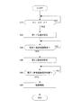
- FIG. 2 is a flowchart showing a flow of power generation control processing according to an embodiment.
- FIG. 3 is a diagram for explaining the concept of power generation restriction.
- FIG. 4 is a diagram for explaining the concept of power generation restriction when regenerative power is generated.
- FIG. 5 is a diagram for illustrating the concept of power generation restriction when regenerative power is generated beyond a predetermined upper limit value.
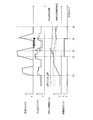
- FIG. 6 is a time chart showing the behavior of the power generation control process of the embodiment.
- FIG. 1 is a block diagram showing a system configuration of a series hybrid vehicle to which a control device of a hybrid vehicle in one embodiment is applied.
- FIG. 1 shows a series hybrid vehicle equipped with a power generation motor (hereinafter referred to as a generator 2) and a drive motor (hereinafter referred to as a drive motor 6).
- a power generation motor hereinafter referred to as a generator 2
- a drive motor hereinafter referred to as a drive motor 6
- the series hybrid vehicle (hereinafter simply referred to as “vehicle”) of this embodiment includes an engine 1, a generator 2, a generator inverter 3, a battery 4, a drive inverter 5, a drive motor 6, and a reduction gear 7. , Vehicle controller 10, and mode SW 15.
- An engine (internal combustion engine) 1 is connected to a generator 2 via a gear (not shown), and transmits power for the generator 2 to generate power to the generator 2.
- the engine 1 is mainly used as a drive source for driving the generator 2 to rotate.
- the generator 2 generates electricity by rotating by power from the engine 1. That is, the driving force of the engine 1 is transmitted to the generator 2, and the generator 2 generates electric power by the driving force of the engine 1. In addition, the generator 2 consumes power by cranking the engine 1 using the power of the generator 2 at the start of the engine 1 or power-running rotation of the engine 1 using the power of the generator 2 Also do motoring.
- the generator inverter 3 is connected to the generator 2, the battery 4, and the drive inverter 5, converts alternating current power generated by the generator 2 into direct current power, and supplies the direct current power to the battery 4. That is, the power generated by the generator 2 is charged to the battery 4.
- the generator inverter 3 converts direct current power supplied from the battery 4 into alternating current power, and supplies the alternating current power to the generator 2.
- the battery 4 charges the power generated by the generator 2 and the regenerated power of the drive motor 6 while discharging the drive power for driving the generator 2 and the drive motor 6.
- the battery 4 of the present embodiment is constituted by a lithium ion battery.
- the drive inverter 5 converts direct current power supplied from the battery 4 or the generator inverter 3 into alternating current power, and supplies it to the drive motor 6. Further, the drive inverter 5 converts alternating current power regenerated and generated by the drive motor 6 into direct current power, and supplies the direct current power to the battery 4.
- the drive motor 6 generates a drive force by the alternating current supplied from the drive inverter 5 and transmits the drive force to the drive wheels through the reduction gear 7.
- the kinetic energy of the vehicle is recovered as electric energy by generating regenerative driving force.
- the recovered electric energy is charged to the battery 4 as regenerative power.
- the vehicle controller 10 includes, for example, a central processing unit (CPU), a read only memory (ROM), a random access memory (RAM), and an input / output interface (I / O interface).
- the vehicle controller 10 calculates a motor torque command value to the drive motor 6 in accordance with information such as the accelerator opening degree, the vehicle speed, and the vehicle state such as the road surface gradient.
- the vehicle controller 10 is a battery based on the mode selected by the mode switch 15 described later, the SOC information of the battery 4, the inputtable power of the battery 4, the outputable power, and the regenerative power of the drive motor 6.
- the target charging power amount of 4 is calculated, and the generated power amount of the generator 2 is controlled to achieve the calculated target charging power amount.
- the vehicle controller 10 controls the engine 1, the generator 2, the generator inverter 3, and the battery 4 in order to adjust the charging power amount of the battery 4 based on the power from the generator 2.
- the vehicle controller 10 controls the engine 1 to achieve the target power generation amount of the generator 2, and the intake air amount by the throttle actuator, the fuel injection amount by the injector, and the ignition timing by the spark plug Adjust according to the status signal such as rotation speed and temperature.
- the specific method of adjusting the charge electric energy of the battery 4 will be described later.
- the vehicle controller 10 measures a state of charge (SOC: State Of Charge) based on the current or voltage charged / discharged to the battery 4. Also, according to the temperature, internal resistance, and SOC of the battery 4, the input enable power and the output enable power of the battery 4 are calculated, and the calculated value is acquired as basic information on the chargeable / dischargeable power of the battery 4.
- SOC State Of Charge
- the vehicle controller 10 performs switching control of the drive inverter 5 in accordance with the state of the rotational speed or voltage of the drive motor 6 so that the drive motor 6 achieves a desired drive torque.
- each function of the vehicle controller 10 mentioned above does not need to be comprised so that the vehicle controller 10 may perform all independently like this embodiment.
- a plurality of controllers may be configured to perform each function in cooperation, such as separately providing an engine controller that controls the engine 1.
- the mode switch (mode SW) 15 is a switch for mode selection (switching) provided so that a driver or a passenger can alternatively select a plurality of travel modes.
- the travel modes selectable by the mode SW 15 include at least the normal mode, the manner mode, and the charge mode.
- each mode will be described focusing on differences with respect to charge and discharge of the battery 4.
- the normal mode is a mode at the time of normal traveling, and is a mode in which charging / discharging of the battery 4 is controlled according to the traveling state.
- the traveling state here is, for example, the SOC of the battery 4 or the like.
- the vehicle controller 10 drives the generator 2 by the engine 1 to charge the battery 4.
- a regenerative braking force corresponding to an engine brake in a general engine drive vehicle is generated.
- the normal mode of the present embodiment is set in an initial state after startup of the vehicle system.
- the manner mode is a mode that enables traveling with less noise than the normal mode.
- charging of the battery 4 based on the power generated by the generator 2 is not performed. Therefore, the vehicle in which the manner mode is selected does not drive the engine 1 for power generation, and travels quietly by the drive motor 6 which uses only the discharge power of the battery 4 as a power source. That is, the driver can intentionally drive the vehicle quietly by selecting the manner mode.
- the charge mode is a mode in which the battery 4 is charged more positively than in the normal mode.
- power generation by the engine 1 is preferentially performed so that the SOC of the battery 4 reaches a preset reference value. That is, it can be said that the charge mode is a mode in which the power generation by the engine 1 is performed in response to the mode operation by the driver or the occupant, as opposed to the normal mode in which the power generation is performed according to the traveling state.
- the power generation by the engine 1 is not performed unless the SOC of the battery 4 falls below the predetermined value (for example, 50% or less), but when the charge mode is selected, the SOC of the battery 4 is temporarily 60%.
- the driver can intentionally increase the SOC of the battery 4 by causing the engine 1 to execute power generation by selecting the charge mode.
- the SOC at the start time of the manner mode to be selected thereafter can be increased, so that the travel distance in the manner mode can be improved. it can.
- the charging of the battery 4 based on the regenerative power of the drive motor 6 is performed with no difference in any of the above travel modes.
- Li deposition protection threshold value which is a threshold value for avoiding deposition of lithium ions inside the battery 4 is set as such an upper limit value.
- the battery 4 (lithium ion battery) has a possibility that lithium ions (metallic lithium) may be deposited inside due to rapid or excessive charging.
- the deposited lithium ions cause the battery 4 to deteriorate by shorting the internal circuit of the battery 4 or the like.
- the Li deposition protection threshold value set in the present embodiment is a value to be compared with the average charging current of the battery 4 in a predetermined time.
- the Li deposition protection threshold value is a threshold value set so as to prevent lithium ions from being deposited inside the battery 4 by suppressing the average charging current amount of the battery 4 in a predetermined time to a value smaller than this.
- 100 seconds is set as the predetermined time, and when the average charging current of the battery 4 in 100 seconds exceeds the Li deposition protection threshold, the charging of the battery 4 is stopped for a predetermined time. Avoid lithium ion precipitation inside.
- the section in which the charging of the battery 4 is stopped in this manner is hereinafter referred to as a "charging prohibited section".
- the predetermined time shown here is an illustration, It is not restricted to this.
- a value capable of determining whether the charging power amount of the battery 4 and the charging speed are in comparison with the Li deposition protection threshold value is appropriately set. For example, two types of 10 seconds and 100 seconds are set as the predetermined time, and when the average charging current of the battery 4 in at least one predetermined time exceeds the Li deposition protection threshold, the charging of the battery 4 is stopped for a predetermined time. You may
- the driver selects the charge mode, as described above, the charging of the battery 4 is actively performed, so the possibility that the charging power amount of the battery 4 exceeds the Li deposition protection threshold value increases. Then, the driver rushes into the charging prohibited section because the average charging current of the battery 4 in a predetermined time exceeds the Li deposition protection threshold although the driver wants to increase the charging power amount of the battery 4 and selects the charging mode. Even in the mode, a state may occur where charging is not performed. As a result, when the charge mode is canceled by selecting the manner mode or the like, a situation may occur in which the amount of charge power of the battery 4 is reduced despite the fact that the charge mode is selected in advance.
- the vehicle controller 10 executes the power generation restriction process for avoiding rushing into the charging prohibited section in the charge mode.
- FIG. 2 is a flowchart showing the power generation limiting process of the present embodiment.
- the vehicle controller 10 is programmed to repeatedly execute the power generation limiting process described below at predetermined intervals.
- step S10 the vehicle controller 10 (hereinafter simply referred to as “the controller 10") determines whether or not the charge mode is selected as the travel mode of the vehicle. If it is determined that the charge mode is selected, the process of step S20 is performed.
- the power generation control applied to the current mode is maintained.
- the controller 10 prohibits the power generation by the engine 1.
- step S20 the controller 10 sets an upper limit value (first upper limit value) of the charging power in the charge mode.
- first upper limit value the charging power amount in the charge mode.
- the charge mode is a mode in which the driver intentionally generates power by driving the engine 1
- the average charging current in a predetermined time tends to increase, and it is easier to enter the charging prohibited section than in the normal mode. Therefore, in this step, the upper limit value of the charging power amount in the charge mode is set smaller than that in the normal mode.
- the charging power amount based on the regenerative power of the drive motor 6 is not limited by the first upper limit value and the second upper limit value described later.
- the first upper limit value of the present embodiment is set to several tens of kW, the value is about half of the upper limit value (normal time upper limit value) of the charging power in the normal mode. Further, the first upper limit value may be adjusted in accordance with at least one of the temperature, the SOC, and the vehicle speed of the battery 4 in consideration of the characteristics related to the internal resistance value of the battery 4 and the like. In the present embodiment, when the temperature, the SOC, and the vehicle speed of the battery 4 increase, the first upper limit value is set to a larger value.
- step S30 the controller 10 determines whether the average charging current amount of the battery 4 in a predetermined time exceeds a predetermined "power generation limit threshold".
- the “power generation limit threshold value” is a threshold value set to prevent the average charging power amount per predetermined time of the battery 4 from exceeding the above-described Li deposition protection threshold value in the charge mode. Therefore, the power generation limit threshold is set to a value smaller than the Li deposition protection threshold. Moreover, the same time as the above-mentioned predetermined time used in the comparison with the Li deposition protection threshold value is applied as the predetermined time here.
- the Li deposition protection threshold value and the power generation limit threshold value of the present embodiment are also adjusted in accordance with at least one of the temperature of the battery 4 and the SOC in consideration of the characteristics related to the internal resistance value and the like of the battery 4. For example, in the present embodiment, the lower the temperature or the SOC of the battery 4, the lower the Li deposition protection threshold value and the power generation limit threshold value. In addition, it is not necessary that the reduction width when adjusting the Li deposition protection threshold value and the power generation limit threshold value according to the temperature etc. is the same. In the present embodiment, the reduction range of the power generation limit threshold is adjusted to be larger than the reduction range of the Li deposition protection threshold. That is, the difference between the Li deposition protection threshold value and the power generation limit threshold value is adjusted to be larger as the temperature or the SOC of the battery 4 decreases.
- step 30 If it is determined in step 30 that the average charging current amount of the battery 4 in the predetermined time exceeds the power generation limit threshold value, the process of the subsequent step S40 is executed to further limit the charging power amount of the battery 4. If it is determined that the average charging current amount does not exceed the power generation limit threshold, the process of step S30 is repeatedly executed until it is determined that the power generation limit threshold is exceeded.
- step S40 the controller 10 sets a second upper limit value as the upper limit value of the charging power in the charge mode, in order to prevent the battery 4 from entering the charge inhibition period.
- the second upper limit is set to a value lower than the first upper limit.
- FIG. 3 is a view for explaining the concept of power generation restriction in an operating state (power running operating state) in which regenerative power is not generated.
- the second upper limit is set to a value lower than the first upper limit (a few kW in the present embodiment)
- the controller 10 after the second upper limit is set in step S40 is a battery.
- the amount of power generation of the engine 1 is controlled so that the charging power of 4 falls within the range of the double arrow a. For example, if the charging power reaches a second upper limit value, the generated power of the engine 1 is for operating the driving motor 6 and the auxiliary equipment with an amount of charging power corresponding to the second upper limit value. It becomes the electric power (double arrow a + b) which added power consumption.
- FIG. 4 is a diagram for explaining the concept of power generation restriction in an operating state in which regenerative power is generated.
- the controller 10 after the second upper limit value is set is a power (double arrow c + d) obtained by adding the regenerative power and the generated power.
- the amount of power generation of the engine 1 is controlled so as not to exceed the second upper limit value. For example, if the charge power reaches a second upper limit value, the amount of power generation of the engine 1 is the power obtained by subtracting the regenerative power from the second upper limit value (double arrow c).
- the limitation using the first upper limit value can be similarly explained by replacing the second upper limit value in the drawing with the first upper limit value.
- FIG. 5 is a diagram for explaining the concept of power generation restriction in an operating state in which regenerative power of an amount exceeding the second upper limit value is generated. Since the charging power amount based on the regenerative power of the drive motor 6 is not limited by the first upper limit value or the second upper limit value, the charging power based on the regenerative power may exceed the second upper limit value as illustrated.
- the engine 1 when the generated power is controlled so that the sum of the regenerated power and the generated power does not exceed the second upper limit, the engine 1 is stopped when the regenerated power exceeds the second upper limit. The engine 1 needs to be driven when the regenerative power falls below the second upper limit value.
- the charge mode is a mode in which the driver intentionally charges the vehicle by intentionally driving the engine 1, the state in which the engine 1 is not driven although the charge mode is selected is a state against the driver's expectation. Can be provided.
- the controller 10 after the second upper limit value is set is the amount of electric power generated by the engine 1 even when regenerative electric power of an amount exceeding the second upper limit value is generated as illustrated. It controls in the range which does not exceed the 2nd upper limit with the charging electric power based on the electric power generation amount of 1.
- the upper limit of the charge power based on the power generated by engine 1 in this state may be a power corresponding to the second upper limit, or may be set to a smaller value according to the regenerative power etc. Good.
- charging power based on the amount of power generation of the engine 1 may be set to zero. That is, the controller 10 can also stop the power generation by the engine 1 when the amount of regenerative power exceeding the second upper limit value is generated.
- the limitation using the first upper limit value can be similarly explained by replacing the second upper limit value in the drawing with the first upper limit value.
- the maximum value of the charging power based on the power generation amount of the engine 1 is the second upper limit equivalent amount Is preferred.
- step S40 by setting the second upper limit value lower than the first upper limit value set in step S20, the charge amount in the charge mode is within the range up to the first upper limit value.
- the second upper limit is set while increasing the amount early, after that, the possibility of the average charge power reaching the Li deposition protection threshold is further suppressed, and the state of the battery 4 rushes into the charge inhibition zone in the charge mode. Can be avoided.
- the process of step S50 is executed.
- step S50 the controller 10 determines whether the average charging current amount of the battery 4 in a predetermined time falls below the "power generation restriction cancellation threshold value".
- the “power generation restriction cancellation threshold value” is a threshold value set to determine whether or not to cancel the power generation restriction by the second upper limit value.
- the power generation restriction cancellation threshold is the restriction cancellation hysteresis with respect to the power generation restriction threshold in the power generation control in the charge mode. If it is determined that the average charge current amount of the battery 4 has fallen below the power generation restriction cancellation threshold value, the process of step S60 is executed. If it is determined that the average charge current amount is not below the power generation restriction release threshold, the process of step S50 is repeatedly executed until it is determined that the average charge current amount is below the power generation restriction release threshold.
- step S60 the controller 10 cancels the second upper limit value to stop the power generation restriction after step S40, and ends the power generation restriction process according to the present flow.
- the above is the contents of the power generation limiting process in the charge mode performed by the controller 10 of the present embodiment. Subsequently, an actual example when the above-described power generation limiting process is executed will be described with reference to a time chart.
- FIG. 6 is a time chart showing the behavior of the power generation limiting process in the charge mode.
- FIG. 6 shows, from the top, vehicle speed [km / h], generated power by engine 1 [kW], average charging current of battery 4 for a predetermined time (100 sec in this case) [A], and power generation restriction flag (0 or 1). ) Is shown.
- the horizontal axis is time [sec].
- the solid lines shown in the power generated by the engine 1 [kW] and the average charging current of the battery 4 [A] indicate the state in which the first upper limit value is set by the selection of the charge mode.
- the behavior of the value is shown, and the dotted line portion shows the behavior of each value in the state where the second upper limit is set by the power generation restriction.
- the average charging current [A] of the battery 4 is shown together with the Li deposition protection threshold value indicated by the dotted line and the power generation limitation threshold value and the power generation restriction release threshold value indicated by the alternate long and short dashed line.
- the average charge current [A] and the charge power [kW] are always It shows a positive value.
- power generation by the engine 1 may be exceptionally stopped due to a safety requirement.
- the generator 2 is driven by battery power even in the charge mode to generate negative pressure in the intake passage of the engine. Motoring control may be performed to operate the.
- the generated power sharply increases in response to the rise of the vehicle speed, and the average charging current thereafter tends to increase.
- the average charging current gradually increases over time t2 while being limited so that the increase slope does not exceed the first upper limit value.
- the SOC of the generated power of the engine 1 is achieved by setting the first upper limit value so as to make the increase slope of the average charging current relatively smaller than that in the normal mode. The risk of rushing into the charging prohibited section can be suppressed while increasing
- the generated power is further limited, and the increase inclination of the average charging current is further suppressed (see the dotted line), so the increasing tendency of the average charging current becomes gentle after time t2.
- the amount of power generation (power generation limitation amount) limited by the power generation limitation is appropriately adjusted according to the temperature of the battery 4 and the vehicle speed. For example, when the temperature of the battery 4 or the vehicle speed increases, the power generation limit amount may be adjusted to be larger.
- the power generation control based only on the first upper limit value is executed without providing the second upper limit value, the average charging current will continue to increase after time t2 (see solid line).
- the deposition protection threshold is exceeded.
- the charging prohibition zone is entered, and charging is prohibited for a certain period regardless of the charge mode.
- the average charging current can be prevented from exceeding the Li deposition protection threshold by restricting the increase slope of the average charging current to a smaller value by the second upper limit value, charging is constant regardless of the charge mode. It is possible to avoid a situation that is prohibited for a period. Then, under the limitation of the second upper limit value, the average charging current gradually decreases over time t4.
- the controller 10 cancels the power generation restriction and changes the upper limit value of the charging power from the second upper limit value to the first upper limit value due to the average charging current falling below the power generation restriction cancellation threshold.
- Generation restriction flag 0
- the SOC of the battery 4 gradually increases over time t5.
- the second upper limit value is not provided, since the charging prohibition zone is entered at time t3, the power is reduced by the driving of the drive motor 6 although the battery 4 is not charged. Continue to be consumed.
- the SOC of the battery 4 after the charge mode is turned off for example, time t5
- the control device of the hybrid vehicle controls the engine 1, the battery 4 for charging the power generated by the engine 1, the motor 6 as a drive source, and a plurality of traveling modes selectable by mode operation.
- the control device of the hybrid vehicle includes, as a traveling mode, a normal mode in which charging and discharging of the battery are performed in accordance with the traveling state, and a charge mode in which power generation by the engine is performed in accordance with mode operation.
- the upper limit (first upper limit) of the charging power based on the generated power at the time is made smaller than the upper limit (normal upper limit) of the charging power based on the generated power in the normal mode.
- the amount of power generated by the engine 1 is limited so that the amount of charge power of the battery 4 does not exceed the first upper limit value.
- the average charging current in a predetermined time tends to increase, and while the SOC of the battery 4 is increased according to the driver's request, charging of a predetermined amount or more is avoided, and the state of the battery 4 is charged. It is possible to reduce the risk of entering a prohibited section.
- the controller 10 when the amount of charge power in a predetermined time in the charge mode exceeds a predetermined value (power generation limit threshold), the controller 10 performs the charge mode.
- the upper limit value of hour is further decreased (a second upper limit value is set).
- the controller 10 sets the upper limit value of the charging power based on the generated power in the charge mode, Reduce according to the amount of regenerative power. As a result, the power generated by the engine 1 can be controlled while considering the regenerative power, and the charging power of the battery 4 can be appropriately controlled within the set upper limit value range.
- the controller 10 adjusts the upper limit value (the first upper limit value, the second upper limit value) in accordance with the temperature of the battery 4. As a result, even if the characteristics such as the internal resistance change due to the temperature change of the battery 4, it is possible to stably execute the power generation control that suppresses the state of the battery 4 from entering the charging prohibited section.
- the embodiment of the present invention was described, the above-mentioned embodiment showed only a part of application example of the present invention, and in the meaning of limiting the technical scope of the present invention to the concrete composition of the above-mentioned embodiment. Absent.
- the index in power generation control or each value to be controlled is not limited to those described above.
- the generated power [kW] by the engine 1 may be replaced by the generated current [A] by the engine 1, and the average charging current [A] may be replaced by the average charging power [kW].
- the average charging current per predetermined time may be an integrated value (sum) of the charging current in the predetermined time. That is, the power generation control described above can be performed using not only each index such as the current value used in the above-described embodiment, but also another index that is proportional to the index.
Landscapes
- Engineering & Computer Science (AREA)
- Transportation (AREA)
- Mechanical Engineering (AREA)
- Chemical & Material Sciences (AREA)
- Combustion & Propulsion (AREA)
- Power Engineering (AREA)
- Automation & Control Theory (AREA)
- Life Sciences & Earth Sciences (AREA)
- Sustainable Development (AREA)
- Sustainable Energy (AREA)
- Human Computer Interaction (AREA)
- Electric Propulsion And Braking For Vehicles (AREA)
- Hybrid Electric Vehicles (AREA)
Abstract
Priority Applications (9)
| Application Number | Priority Date | Filing Date | Title |
|---|---|---|---|
| EP17934706.7A EP3725614B1 (fr) | 2017-12-15 | 2017-12-15 | Procédé et dispositif de commande de véhicule hybride |
| PCT/JP2017/045210 WO2019116576A1 (fr) | 2017-12-15 | 2017-12-15 | Procédé et dispositif de commande de véhicule hybride |
| RU2020119770A RU2746116C1 (ru) | 2017-12-15 | 2017-12-15 | Способ и устройство для управления зарядом гибридного транспортного средства |
| CN201780097646.8A CN111479733B (zh) | 2017-12-15 | 2017-12-15 | 混合动力车辆的控制方法和控制装置 |
| US16/771,972 US11518363B2 (en) | 2017-12-15 | 2017-12-15 | Method and device for controlling hybrid vehicle |
| BR112020011919-9A BR112020011919B1 (pt) | 2017-12-15 | Método e dispositivo para o controle de veículo híbrido | |
| MX2020006152A MX2020006152A (es) | 2017-12-15 | 2017-12-15 | Metodo y dispositivo para controlar vehiculo hibrido. |
| KR1020207018229A KR102352463B1 (ko) | 2017-12-15 | 2017-12-15 | 하이브리드 차량의 제어 방법, 및 제어 장치 |
| JP2019558865A JP6927328B2 (ja) | 2017-12-15 | 2017-12-15 | ハイブリッド車両の制御方法、及び、制御装置 |
Applications Claiming Priority (1)
| Application Number | Priority Date | Filing Date | Title |
|---|---|---|---|
| PCT/JP2017/045210 WO2019116576A1 (fr) | 2017-12-15 | 2017-12-15 | Procédé et dispositif de commande de véhicule hybride |
Publications (1)
| Publication Number | Publication Date |
|---|---|
| WO2019116576A1 true WO2019116576A1 (fr) | 2019-06-20 |
Family
ID=66820187
Family Applications (1)
| Application Number | Title | Priority Date | Filing Date |
|---|---|---|---|
| PCT/JP2017/045210 Ceased WO2019116576A1 (fr) | 2017-12-15 | 2017-12-15 | Procédé et dispositif de commande de véhicule hybride |
Country Status (8)
| Country | Link |
|---|---|
| US (1) | US11518363B2 (fr) |
| EP (1) | EP3725614B1 (fr) |
| JP (1) | JP6927328B2 (fr) |
| KR (1) | KR102352463B1 (fr) |
| CN (1) | CN111479733B (fr) |
| MX (1) | MX2020006152A (fr) |
| RU (1) | RU2746116C1 (fr) |
| WO (1) | WO2019116576A1 (fr) |
Cited By (1)
| Publication number | Priority date | Publication date | Assignee | Title |
|---|---|---|---|---|
| JPWO2022038718A1 (fr) * | 2020-08-19 | 2022-02-24 |
Families Citing this family (14)
| Publication number | Priority date | Publication date | Assignee | Title |
|---|---|---|---|---|
| US11529944B2 (en) * | 2017-12-15 | 2022-12-20 | Nissan Motor Co., Ltd. | Control method for hybrid vehicle and control apparatus for hybrid vehicle |
| EP3941783B1 (fr) * | 2019-03-20 | 2023-06-07 | Volvo Truck Corporation | Procédé de commande d'un système de stockage d'énergie d'un véhicule |
| US12351028B1 (en) | 2021-08-13 | 2025-07-08 | Oshkosh Defense, Llc | Military vehicle with modular battery units |
| US12319160B1 (en) | 2021-08-13 | 2025-06-03 | Oshkosh Defense, Llc | Convoy operations for electrified military vehicles |
| US12311754B1 (en) | 2021-08-13 | 2025-05-27 | Oshkosh Defense, Llc | Power export system for a military vehicle |
| US12030479B1 (en) | 2021-08-13 | 2024-07-09 | Oshkosh Defense, Llc | Prioritized charging of an energy storage system of a military vehicle |
| US12583309B1 (en) | 2021-08-13 | 2026-03-24 | Oshkosh Defense, Llc | Hybrid power system for a military vehicle |
| US12130122B1 (en) | 2021-08-13 | 2024-10-29 | Oshkosh Defense, Llc | Military vehicle with battery armor |
| US12358361B1 (en) | 2021-08-13 | 2025-07-15 | Oshkosh Defense, Llc | Electrified military vehicle with electric weaponry support system |
| US12060053B1 (en) | 2021-08-13 | 2024-08-13 | Oshkosh Defense, Llc | Military vehicle with control modes |
| US12083995B1 (en) | 2021-08-13 | 2024-09-10 | Oshkosh Defense, Llc | Power export system for a military vehicle |
| US11498409B1 (en) | 2021-08-13 | 2022-11-15 | Oshkosh Defense, Llc | Electrified military vehicle |
| US11608050B1 (en) | 2021-08-13 | 2023-03-21 | Oshkosh Defense, Llc | Electrified military vehicle |
| JP2023110657A (ja) * | 2022-01-28 | 2023-08-09 | 株式会社クボタ | 電動作業車 |
Citations (5)
| Publication number | Priority date | Publication date | Assignee | Title |
|---|---|---|---|---|
| JPH08168103A (ja) * | 1994-12-12 | 1996-06-25 | Toyota Motor Corp | ハイブリッド型電気自動車 |
| JP2001057709A (ja) * | 1999-08-17 | 2001-02-27 | Honda Motor Co Ltd | ハイブリッド車両の制御装置 |
| JP2005080330A (ja) * | 2003-08-28 | 2005-03-24 | Toyota Motor Corp | 蓄電機構の制御装置 |
| JP2009240116A (ja) | 2008-03-28 | 2009-10-15 | Suzuki Motor Corp | 車両用発電機の制御装置 |
| JP2014118079A (ja) * | 2012-12-18 | 2014-06-30 | Mitsubishi Motors Corp | ハイブリッド車の充電制御装置 |
Family Cites Families (6)
| Publication number | Priority date | Publication date | Assignee | Title |
|---|---|---|---|---|
| US7746026B2 (en) * | 2006-12-22 | 2010-06-29 | Chrysler Group Llc | Controlling state of charge of a vehicle battery |
| JP5146502B2 (ja) * | 2009-11-12 | 2013-02-20 | トヨタ自動車株式会社 | 二次電池の充放電制御装置 |
| CN102648105B (zh) * | 2009-11-17 | 2014-10-29 | 丰田自动车株式会社 | 车辆及车辆的控制方法 |
| JP6354141B2 (ja) | 2013-12-04 | 2018-07-11 | トヨタ自動車株式会社 | 充電制御装置 |
| JP6164245B2 (ja) * | 2015-04-24 | 2017-07-19 | トヨタ自動車株式会社 | 車両の制御装置および車両の制御方法 |
| US11697355B2 (en) * | 2018-08-22 | 2023-07-11 | Ford Global Technologies, Llc | Electrified vehicle electrical distribution system component protection systems and methods |
-
2017
- 2017-12-15 JP JP2019558865A patent/JP6927328B2/ja active Active
- 2017-12-15 US US16/771,972 patent/US11518363B2/en active Active
- 2017-12-15 MX MX2020006152A patent/MX2020006152A/es unknown
- 2017-12-15 CN CN201780097646.8A patent/CN111479733B/zh active Active
- 2017-12-15 EP EP17934706.7A patent/EP3725614B1/fr active Active
- 2017-12-15 RU RU2020119770A patent/RU2746116C1/ru active
- 2017-12-15 WO PCT/JP2017/045210 patent/WO2019116576A1/fr not_active Ceased
- 2017-12-15 KR KR1020207018229A patent/KR102352463B1/ko not_active Expired - Fee Related
Patent Citations (5)
| Publication number | Priority date | Publication date | Assignee | Title |
|---|---|---|---|---|
| JPH08168103A (ja) * | 1994-12-12 | 1996-06-25 | Toyota Motor Corp | ハイブリッド型電気自動車 |
| JP2001057709A (ja) * | 1999-08-17 | 2001-02-27 | Honda Motor Co Ltd | ハイブリッド車両の制御装置 |
| JP2005080330A (ja) * | 2003-08-28 | 2005-03-24 | Toyota Motor Corp | 蓄電機構の制御装置 |
| JP2009240116A (ja) | 2008-03-28 | 2009-10-15 | Suzuki Motor Corp | 車両用発電機の制御装置 |
| JP2014118079A (ja) * | 2012-12-18 | 2014-06-30 | Mitsubishi Motors Corp | ハイブリッド車の充電制御装置 |
Cited By (2)
| Publication number | Priority date | Publication date | Assignee | Title |
|---|---|---|---|---|
| JPWO2022038718A1 (fr) * | 2020-08-19 | 2022-02-24 | ||
| JP7205650B2 (ja) | 2020-08-19 | 2023-01-17 | 日産自動車株式会社 | ハイブリッド車両の制御方法及びハイブリッド車両の制御装置 |
Also Published As
| Publication number | Publication date |
|---|---|
| KR102352463B1 (ko) | 2022-01-18 |
| US20210213934A1 (en) | 2021-07-15 |
| EP3725614A1 (fr) | 2020-10-21 |
| CN111479733A (zh) | 2020-07-31 |
| BR112020011919A2 (pt) | 2020-11-24 |
| US11518363B2 (en) | 2022-12-06 |
| KR20200088885A (ko) | 2020-07-23 |
| EP3725614B1 (fr) | 2025-03-12 |
| RU2746116C1 (ru) | 2021-04-07 |
| CN111479733B (zh) | 2023-10-20 |
| JP6927328B2 (ja) | 2021-09-01 |
| JPWO2019116576A1 (ja) | 2021-01-07 |
| EP3725614A4 (fr) | 2021-01-06 |
| MX2020006152A (es) | 2020-08-13 |
Similar Documents
| Publication | Publication Date | Title |
|---|---|---|
| JP6927328B2 (ja) | ハイブリッド車両の制御方法、及び、制御装置 | |
| JP6919720B2 (ja) | ハイブリッド車両の制御方法、及び、制御装置 | |
| CN107826099B (zh) | 用于混合动力车辆的操作控制系统 | |
| US20130030634A1 (en) | Control device for hybrid vehicle, and hybrid vehicle incorporating control device | |
| KR20140135246A (ko) | 하이브리드 자동차의 발전 제어 시스템 | |
| JP2011255824A (ja) | ハイブリッド車の制御装置 | |
| JP3094701B2 (ja) | 電気自動車用エンジン駆動発電機の制御装置 | |
| JP2018008544A (ja) | ハイブリッド車両 | |
| JP2004229447A (ja) | 車両用電源装置 | |
| EP4400376B1 (fr) | Procédé de commande de véhicule et véhicule | |
| JP6693407B2 (ja) | ハイブリッド車両 | |
| JP2010233396A (ja) | 電動車両のモータ制御装置 | |
| JP6497807B2 (ja) | 電気自動車 | |
| JP7204508B2 (ja) | 車両 | |
| WO2019116559A1 (fr) | Procédé de commande de dispositif électrique, et dispositif électrique | |
| JP2006325293A (ja) | 発電制御システム | |
| JP2011225077A (ja) | ハイブリッド自動車 | |
| WO2026083487A1 (fr) | Dispositif de commande d'entraînement pour véhicule hybride | |
| JP2024020029A (ja) | ハイブリッド車両の制御装置 | |
| JP2002369305A (ja) | 電気自動車用回生制御装置 | |
| JP2019157693A (ja) | 車両の電力制御装置 | |
| BR112020011919B1 (pt) | Método e dispositivo para o controle de veículo híbrido |
Legal Events
| Date | Code | Title | Description |
|---|---|---|---|
| 121 | Ep: the epo has been informed by wipo that ep was designated in this application |
Ref document number: 17934706 Country of ref document: EP Kind code of ref document: A1 |
|
| ENP | Entry into the national phase |
Ref document number: 2019558865 Country of ref document: JP Kind code of ref document: A |
|
| NENP | Non-entry into the national phase |
Ref country code: DE |
|
| ENP | Entry into the national phase |
Ref document number: 20207018229 Country of ref document: KR Kind code of ref document: A |
|
| ENP | Entry into the national phase |
Ref document number: 2017934706 Country of ref document: EP Effective date: 20200715 |
|
| REG | Reference to national code |
Ref country code: BR Ref legal event code: B01A Ref document number: 112020011919 Country of ref document: BR |
|
| ENP | Entry into the national phase |
Ref document number: 112020011919 Country of ref document: BR Kind code of ref document: A2 Effective date: 20200612 |