WO2019116580A1 - Dispositif de division de boîte en carton et dispositif de fabrication de boîte en carton - Google Patents
Dispositif de division de boîte en carton et dispositif de fabrication de boîte en carton Download PDFInfo
- Publication number
- WO2019116580A1 WO2019116580A1 PCT/JP2017/045214 JP2017045214W WO2019116580A1 WO 2019116580 A1 WO2019116580 A1 WO 2019116580A1 JP 2017045214 W JP2017045214 W JP 2017045214W WO 2019116580 A1 WO2019116580 A1 WO 2019116580A1
- Authority
- WO
- WIPO (PCT)
- Prior art keywords
- cardboard box
- positioning member
- downstream
- cardboard
- box
- Prior art date
- Legal status (The legal status is an assumption and is not a legal conclusion. Google has not performed a legal analysis and makes no representation as to the accuracy of the status listed.)
- Ceased
Links
Images






Classifications
-
- B—PERFORMING OPERATIONS; TRANSPORTING
- B31—MAKING ARTICLES OF PAPER, CARDBOARD OR MATERIAL WORKED IN A MANNER ANALOGOUS TO PAPER; WORKING PAPER, CARDBOARD OR MATERIAL WORKED IN A MANNER ANALOGOUS TO PAPER
- B31B—MAKING CONTAINERS OF PAPER, CARDBOARD OR MATERIAL WORKED IN A MANNER ANALOGOUS TO PAPER
- B31B50/00—Making rigid or semi-rigid containers, e.g. boxes or cartons
- B31B50/14—Cutting, e.g. perforating, punching, slitting or trimming
- B31B50/20—Cutting sheets or blanks
-
- B—PERFORMING OPERATIONS; TRANSPORTING
- B26—HAND CUTTING TOOLS; CUTTING; SEVERING
- B26D—CUTTING; DETAILS COMMON TO MACHINES FOR PERFORATING, PUNCHING, CUTTING-OUT, STAMPING-OUT OR SEVERING
- B26D1/00—Cutting through work characterised by the nature or movement of the cutting member or particular materials not otherwise provided for; Apparatus or machines therefor; Cutting members therefor
- B26D1/01—Cutting through work characterised by the nature or movement of the cutting member or particular materials not otherwise provided for; Apparatus or machines therefor; Cutting members therefor involving a cutting member which does not travel with the work
- B26D1/02—Cutting through work characterised by the nature or movement of the cutting member or particular materials not otherwise provided for; Apparatus or machines therefor; Cutting members therefor involving a cutting member which does not travel with the work having a stationary cutting member
- B26D1/025—Cutting through work characterised by the nature or movement of the cutting member or particular materials not otherwise provided for; Apparatus or machines therefor; Cutting members therefor involving a cutting member which does not travel with the work having a stationary cutting member for thin material, e.g. for sheets, strips or the like
-
- B—PERFORMING OPERATIONS; TRANSPORTING
- B26—HAND CUTTING TOOLS; CUTTING; SEVERING
- B26D—CUTTING; DETAILS COMMON TO MACHINES FOR PERFORATING, PUNCHING, CUTTING-OUT, STAMPING-OUT OR SEVERING
- B26D1/00—Cutting through work characterised by the nature or movement of the cutting member or particular materials not otherwise provided for; Apparatus or machines therefor; Cutting members therefor
- B26D1/01—Cutting through work characterised by the nature or movement of the cutting member or particular materials not otherwise provided for; Apparatus or machines therefor; Cutting members therefor involving a cutting member which does not travel with the work
- B26D1/04—Cutting through work characterised by the nature or movement of the cutting member or particular materials not otherwise provided for; Apparatus or machines therefor; Cutting members therefor involving a cutting member which does not travel with the work having a linearly-movable cutting member
- B26D1/06—Cutting through work characterised by the nature or movement of the cutting member or particular materials not otherwise provided for; Apparatus or machines therefor; Cutting members therefor involving a cutting member which does not travel with the work having a linearly-movable cutting member wherein the cutting member reciprocates
- B26D1/08—Cutting through work characterised by the nature or movement of the cutting member or particular materials not otherwise provided for; Apparatus or machines therefor; Cutting members therefor involving a cutting member which does not travel with the work having a linearly-movable cutting member wherein the cutting member reciprocates of the guillotine type
- B26D1/085—Cutting through work characterised by the nature or movement of the cutting member or particular materials not otherwise provided for; Apparatus or machines therefor; Cutting members therefor involving a cutting member which does not travel with the work having a linearly-movable cutting member wherein the cutting member reciprocates of the guillotine type for thin material, e.g. for sheets, strips or the like
-
- B—PERFORMING OPERATIONS; TRANSPORTING
- B26—HAND CUTTING TOOLS; CUTTING; SEVERING
- B26D—CUTTING; DETAILS COMMON TO MACHINES FOR PERFORATING, PUNCHING, CUTTING-OUT, STAMPING-OUT OR SEVERING
- B26D1/00—Cutting through work characterised by the nature or movement of the cutting member or particular materials not otherwise provided for; Apparatus or machines therefor; Cutting members therefor
- B26D1/01—Cutting through work characterised by the nature or movement of the cutting member or particular materials not otherwise provided for; Apparatus or machines therefor; Cutting members therefor involving a cutting member which does not travel with the work
- B26D1/46—Cutting through work characterised by the nature or movement of the cutting member or particular materials not otherwise provided for; Apparatus or machines therefor; Cutting members therefor involving a cutting member which does not travel with the work having an endless band-knife or the like
- B26D1/465—Cutting through work characterised by the nature or movement of the cutting member or particular materials not otherwise provided for; Apparatus or machines therefor; Cutting members therefor involving a cutting member which does not travel with the work having an endless band-knife or the like for thin material, e.g. for sheets, strips or the like
-
- B—PERFORMING OPERATIONS; TRANSPORTING
- B26—HAND CUTTING TOOLS; CUTTING; SEVERING
- B26D—CUTTING; DETAILS COMMON TO MACHINES FOR PERFORATING, PUNCHING, CUTTING-OUT, STAMPING-OUT OR SEVERING
- B26D7/00—Details of apparatus for cutting, cutting-out, stamping-out, punching, perforating, or severing by means other than cutting
- B26D7/01—Means for holding or positioning work
- B26D7/015—Means for holding or positioning work for sheet material or piles of sheets
-
- B—PERFORMING OPERATIONS; TRANSPORTING
- B31—MAKING ARTICLES OF PAPER, CARDBOARD OR MATERIAL WORKED IN A MANNER ANALOGOUS TO PAPER; WORKING PAPER, CARDBOARD OR MATERIAL WORKED IN A MANNER ANALOGOUS TO PAPER
- B31B—MAKING CONTAINERS OF PAPER, CARDBOARD OR MATERIAL WORKED IN A MANNER ANALOGOUS TO PAPER
- B31B50/00—Making rigid or semi-rigid containers, e.g. boxes or cartons
- B31B50/005—Making rigid or semi-rigid containers, e.g. boxes or cartons involving a particular layout of the machinery or relative arrangement of its subunits
-
- B—PERFORMING OPERATIONS; TRANSPORTING
- B31—MAKING ARTICLES OF PAPER, CARDBOARD OR MATERIAL WORKED IN A MANNER ANALOGOUS TO PAPER; WORKING PAPER, CARDBOARD OR MATERIAL WORKED IN A MANNER ANALOGOUS TO PAPER
- B31B—MAKING CONTAINERS OF PAPER, CARDBOARD OR MATERIAL WORKED IN A MANNER ANALOGOUS TO PAPER
- B31B50/00—Making rigid or semi-rigid containers, e.g. boxes or cartons
- B31B50/02—Feeding or positioning sheets, blanks or webs
- B31B50/04—Feeding sheets or blanks
- B31B50/06—Feeding sheets or blanks from stacks
-
- B—PERFORMING OPERATIONS; TRANSPORTING
- B31—MAKING ARTICLES OF PAPER, CARDBOARD OR MATERIAL WORKED IN A MANNER ANALOGOUS TO PAPER; WORKING PAPER, CARDBOARD OR MATERIAL WORKED IN A MANNER ANALOGOUS TO PAPER
- B31B—MAKING CONTAINERS OF PAPER, CARDBOARD OR MATERIAL WORKED IN A MANNER ANALOGOUS TO PAPER
- B31B50/00—Making rigid or semi-rigid containers, e.g. boxes or cartons
- B31B50/25—Surface scoring
- B31B50/256—Surface scoring using tools mounted on a drum
-
- B—PERFORMING OPERATIONS; TRANSPORTING
- B31—MAKING ARTICLES OF PAPER, CARDBOARD OR MATERIAL WORKED IN A MANNER ANALOGOUS TO PAPER; WORKING PAPER, CARDBOARD OR MATERIAL WORKED IN A MANNER ANALOGOUS TO PAPER
- B31B—MAKING CONTAINERS OF PAPER, CARDBOARD OR MATERIAL WORKED IN A MANNER ANALOGOUS TO PAPER
- B31B50/00—Making rigid or semi-rigid containers, e.g. boxes or cartons
- B31B50/26—Folding sheets, blanks or webs
-
- B—PERFORMING OPERATIONS; TRANSPORTING
- B31—MAKING ARTICLES OF PAPER, CARDBOARD OR MATERIAL WORKED IN A MANNER ANALOGOUS TO PAPER; WORKING PAPER, CARDBOARD OR MATERIAL WORKED IN A MANNER ANALOGOUS TO PAPER
- B31B—MAKING CONTAINERS OF PAPER, CARDBOARD OR MATERIAL WORKED IN A MANNER ANALOGOUS TO PAPER
- B31B50/00—Making rigid or semi-rigid containers, e.g. boxes or cartons
- B31B50/60—Uniting opposed surfaces or edges; Taping
- B31B50/62—Uniting opposed surfaces or edges; Taping by adhesives
- B31B50/624—Applying glue on blanks
-
- B—PERFORMING OPERATIONS; TRANSPORTING
- B31—MAKING ARTICLES OF PAPER, CARDBOARD OR MATERIAL WORKED IN A MANNER ANALOGOUS TO PAPER; WORKING PAPER, CARDBOARD OR MATERIAL WORKED IN A MANNER ANALOGOUS TO PAPER
- B31B—MAKING CONTAINERS OF PAPER, CARDBOARD OR MATERIAL WORKED IN A MANNER ANALOGOUS TO PAPER
- B31B50/00—Making rigid or semi-rigid containers, e.g. boxes or cartons
- B31B50/74—Auxiliary operations
- B31B50/92—Delivering
- B31B50/98—Delivering in stacks or bundles
-
- B—PERFORMING OPERATIONS; TRANSPORTING
- B26—HAND CUTTING TOOLS; CUTTING; SEVERING
- B26D—CUTTING; DETAILS COMMON TO MACHINES FOR PERFORATING, PUNCHING, CUTTING-OUT, STAMPING-OUT OR SEVERING
- B26D7/00—Details of apparatus for cutting, cutting-out, stamping-out, punching, perforating, or severing by means other than cutting
- B26D7/27—Means for performing other operations combined with cutting
- B26D7/32—Means for performing other operations combined with cutting for conveying or stacking cut product
- B26D2007/322—Means for performing other operations combined with cutting for conveying or stacking cut product the cut products being sheets, e.g. sheets of paper
-
- B—PERFORMING OPERATIONS; TRANSPORTING
- B26—HAND CUTTING TOOLS; CUTTING; SEVERING
- B26D—CUTTING; DETAILS COMMON TO MACHINES FOR PERFORATING, PUNCHING, CUTTING-OUT, STAMPING-OUT OR SEVERING
- B26D7/00—Details of apparatus for cutting, cutting-out, stamping-out, punching, perforating, or severing by means other than cutting
- B26D7/06—Arrangements for feeding or delivering work of other than sheet, web, or filamentary form
- B26D7/0675—Arrangements for feeding or delivering work of other than sheet, web, or filamentary form specially adapted for piles of sheets
-
- B—PERFORMING OPERATIONS; TRANSPORTING
- B31—MAKING ARTICLES OF PAPER, CARDBOARD OR MATERIAL WORKED IN A MANNER ANALOGOUS TO PAPER; WORKING PAPER, CARDBOARD OR MATERIAL WORKED IN A MANNER ANALOGOUS TO PAPER
- B31B—MAKING CONTAINERS OF PAPER, CARDBOARD OR MATERIAL WORKED IN A MANNER ANALOGOUS TO PAPER
- B31B2110/00—Shape of rigid or semi-rigid containers
- B31B2110/30—Shape of rigid or semi-rigid containers having a polygonal cross section
- B31B2110/35—Shape of rigid or semi-rigid containers having a polygonal cross section rectangular, e.g. square
-
- B—PERFORMING OPERATIONS; TRANSPORTING
- B31—MAKING ARTICLES OF PAPER, CARDBOARD OR MATERIAL WORKED IN A MANNER ANALOGOUS TO PAPER; WORKING PAPER, CARDBOARD OR MATERIAL WORKED IN A MANNER ANALOGOUS TO PAPER
- B31B—MAKING CONTAINERS OF PAPER, CARDBOARD OR MATERIAL WORKED IN A MANNER ANALOGOUS TO PAPER
- B31B2120/00—Construction of rigid or semi-rigid containers
- B31B2120/30—Construction of rigid or semi-rigid containers collapsible; temporarily collapsed during manufacturing
- B31B2120/302—Construction of rigid or semi-rigid containers collapsible; temporarily collapsed during manufacturing collapsible into a flat condition
-
- B—PERFORMING OPERATIONS; TRANSPORTING
- B31—MAKING ARTICLES OF PAPER, CARDBOARD OR MATERIAL WORKED IN A MANNER ANALOGOUS TO PAPER; WORKING PAPER, CARDBOARD OR MATERIAL WORKED IN A MANNER ANALOGOUS TO PAPER
- B31B—MAKING CONTAINERS OF PAPER, CARDBOARD OR MATERIAL WORKED IN A MANNER ANALOGOUS TO PAPER
- B31B50/00—Making rigid or semi-rigid containers, e.g. boxes or cartons
- B31B50/14—Cutting, e.g. perforating, punching, slitting or trimming
- B31B50/142—Cutting, e.g. perforating, punching, slitting or trimming using presses or dies
-
- B—PERFORMING OPERATIONS; TRANSPORTING
- B31—MAKING ARTICLES OF PAPER, CARDBOARD OR MATERIAL WORKED IN A MANNER ANALOGOUS TO PAPER; WORKING PAPER, CARDBOARD OR MATERIAL WORKED IN A MANNER ANALOGOUS TO PAPER
- B31B—MAKING CONTAINERS OF PAPER, CARDBOARD OR MATERIAL WORKED IN A MANNER ANALOGOUS TO PAPER
- B31B50/00—Making rigid or semi-rigid containers, e.g. boxes or cartons
- B31B50/74—Auxiliary operations
- B31B50/88—Printing; Embossing
Definitions
- the present invention relates to a cardboard box dividing device for dividing a corrugated cardboard box folded into a flat shape after being subjected to various processes to a cardboard sheet, and to a cardboard box manufacturing apparatus to which the cardboard box dividing device is applied. is there.
- a typical box making machine manufactures a flat cardboard box by processing and folding a cardboard sheet, and a paper feeding unit, a printing unit, a paper discharging unit, a die cutting unit, a folding unit, and a counter ejector. It consists of parts.
- the paper feed unit feeds the corrugated cardboard sheets stacked on the table one by one and sends them to the printing unit at a constant speed.
- the printing unit has a printing unit and performs printing on a cardboard sheet.
- the paper discharge unit forms, on the printed cardboard sheet, creases that become fold lines, and processes the grooves forming the flaps and the adhesive strip for bonding.
- the die cut portion is for punching a hand hole or the like on a corrugated cardboard sheet on which a ruled line, a groove, and a glue strip are formed.
- the folding section applies glue to the glue strip and folds it along the crease while moving the corrugated cardboard sheet on which creases, grooves, glue strips, hand holes, etc. are processed, and bonding the glue strips It manufactures flat cardboard boxes.
- a counter ejector part piles up the corrugated-cardboard sheet which the corrugated-cardboard sheet was folded up and glued, and it divides and discharges it in a predetermined number of batches.
- a box making machine manufactures a cardboard box having a flat shape in which two cardboard boxes are continuous in the transport direction, and a dividing device divides the cardboard box having the flat shape for the two pieces into two pieces, one for one.
- the technology for manufacturing cardboard boxes has been proposed. In the case of this technology, since a box-making machine can continuously produce two cardboard boxes, the time to produce one cardboard box can be shortened and the production efficiency can be improved compared to the prior art. Can.
- a cardboard box dividing apparatus for example, there is one described in Patent Document 1 below.
- the positioning member on the downstream side is awaited and carried in at a position blocking the transport path so that the cardboard box does not overrun from the cutting position.
- the downstream positioning member in order to carry out the cut cardboard box, it is necessary to release the downstream positioning member from the transport path. Therefore, in order to place the released positioning member in the waiting state for loading of the next cardboard box, it can be carried out only after the cut cardboard box passes the positioning member on the downstream side, and high speed in the cutting operation Becoming an obstacle to
- the present invention solves the above-mentioned problems, and by shortening the positioning processing time at the cutting position of the cardboard box, it is possible to speed up the cutting operation and thereby improve the production efficiency. It aims at providing a manufacturing apparatus of
- the present invention provides a cardboard box dividing device according to the present invention having a width in which a continuous cardboard box connected body extends in the thickness direction and intersects the stacked cardboard box connected laminate in the transport direction.
- a cardboard box dividing apparatus for cutting and dividing along a direction, a lower conveyor for stacking and transporting a plurality of connected cardboard boxes, and a conveying direction and thickness direction of the connected cardboard boxes at an upstream portion of the lower conveyor.
- An upstream positioning member movable along the downstream side, a downstream positioning member movable along the transport direction and thickness direction of the connected cardboard box at the downstream portion of the lower conveyor, the upstream positioning member, and the downstream side A positioning drive device capable of independently moving a positioning member; a pressing device for pressing from above the plurality of connected cardboard box assemblies stacked on the lower conveyor; A cutting blade disposed along the width direction of the connector to divide the plurality of cardboard box connectors stacked on the lower conveyor into the front and back; and a plurality of cardboard box connectors on the lower conveyor and the cutter blade And elevating devices relatively moved along the vertical direction.
- a plurality of stacked cardboard box connected bodies are mounted on the lower conveyor, and positioning of the connected cardboard box connected in the transport direction is performed by the upstream positioning member and the downstream positioning member at a predetermined cutting position stopped on the lower conveyor. After that, it is pressed from above by the pressing device, and in this state, the plurality of stacked cardboard box connected bodies are cut by the cutting blade by relative movement of the plurality of connected cardboard box connected bodies and the cutting blade by the lifting device. It is divided.
- a plurality of connected cardboard boxes are unstable in the stacked state, and there is a risk of shifting in the transport direction when stopped at the cutting position, but the plurality of connected cardboard boxes are upstream after stopped at the cutting position.
- the upstream positioning member and the downstream positioning member can be moved independently by the positioning drive device, the upstream positioning member and the downstream positioning member can be separated separately according to the cut state of the connected cardboard box assembly. It can move. As a result, by shortening the positioning process time at the cutting position of the connected cardboard box, it is possible to speed up the cutting operation and improve production efficiency.
- the lifting device includes a lifting platform supporting the lower conveyor and the pressing device, and a lifting drive device lifting the lifting platform, and the positioning drive device includes It is characterized in that the upstream positioning member and the downstream positioning member are operated along the thickness direction of the connected cardboard box body as the elevator platform is moved up and down.
- the upstream positioning member and the downstream positioning member are operated along the thickness direction of the connected cardboard box body by the positioning drive unit along with the elevation of the elevator platform, the elevation operation of the lower conveyor by the elevation drive unit;
- the upstream positioning member and the downstream positioning member can be moved up and down independently by the positioning drive device, and the upstream positioning member and the downstream positioning member position the corrugated cardboard box assembly and the cut corrugated cardboard box It is possible to stably support a plurality of connected cardboard boxes or cardboard boxes with a simple configuration.
- the upstream positioning member and the downstream positioning member each have a telescopic structure in which a support cylinder, an outer cylinder and an inner cylinder are fitted to each other, and the positioning drive device is a support cylinder
- the outer cylinder and the inner cylinder can be moved along the conveying direction of the connected cardboard box body, and the outer cylinder and the inner cylinder can be moved along the thickness direction of the connected cardboard box body with respect to the support cylinder. It is characterized by being possible.
- the apparatus can be miniaturized, and the upstream positioning member and the downstream positioning member can be moved by the positioning drive device in the conveying direction of the corrugated box assembly. By being movable along the thickness direction, positioning with respect to the connected cardboard box can be smoothly performed.
- the upstream positioning member and the downstream positioning member are characterized in that the width in the transport direction of the inner cylinder is narrower than the width in the transport direction of the outer cylinder.
- the narrow inner cylinder descends, so that a gap is secured between the connected cardboard box unit and the inner cylinder, while the plurality of connected cardboard box units descend
- the cut cardboard boxes slightly move to the downstream side and the upstream side in the transport direction, but the movement of the plurality of corrugated boxes is within the clearance and is on the upstream side.
- the plurality of cardboard boxes can be properly supported without the positioning members and the downstream positioning members interfering with the cutting operation of the plurality of connected cardboard box assemblies.
- the positioning drive device transports the downstream positioning member in the conveying direction after the plurality of linked cardboard box assemblies are cut back and forth by the cutting blade and the downstream positioning member is lifted. It is characterized in that it is moved upstream by a predetermined distance.
- downstream positioning member is moved to the upstream side in the transport direction after the downstream positioning member is lifted after the plurality of connected cardboard box bodies are cut, thereby preventing the contact between the downstream positioning member and the cardboard box While, it is possible to prepare for lowering the downstream positioning member early.
- the positioning drive device is configured such that the cut cardboard box passes under the downstream positioning member by the lower conveyor when the downstream positioning member is in the raised position;
- the downstream positioning member may be moved upstream by a predetermined distance in the transport direction.
- downstream positioning member is moved upstream in the transport direction while the cut cardboard box passes below the downstream positioning member, contact between the downstream positioning member and the cardboard box is reliably prevented.
- the positioning drive device lowers the downstream positioning member and also in the transport direction. It is characterized in that it is moved downstream by a predetermined distance.
- downstream positioning member is lowered, so that the downstream positioning member can be prevented from contacting the corrugated box at an early stage while the downstream positioning member is prevented from contacting Can be moved to the positioning position on the downstream side of the cardboard box connected body, and the efficiency of the cutting operation can be improved.
- a paper feed unit for supplying a double box sheet
- a paper discharge unit for performing crease processing on the surface of the double box sheet and grooving
- the double box A folding unit that folds the sheets and joins the end portions to form a linked cardboard box assembly
- a counter ejector unit that stacks the linked cardboard box assembly while counting it and counting
- the linked cardboard box linkages And a dividing device for dividing the cardboard box by cutting the body along a width direction intersecting the transport direction.
- the double box sheet from the paper feed unit is subjected to crease processing and grooving processing at the discharge unit, and folded at the folding unit to join the end portions to form a connected cardboard box body, and the counter ejector unit
- the boxes are stacked while being counted, and cut by a dividing device to produce a cardboard box. Since this dividing device is positioned by the upstream positioning member and the downstream positioning member after stopping at the cutting position, it is possible to cut a plurality of connected cardboard box assemblies with high accuracy.
- the upstream positioning member and the downstream positioning member can be moved independently by the positioning drive device, the upstream positioning member and the downstream positioning member can be separated separately according to the cut state of the connected cardboard box assembly. It can move. As a result, by shortening the positioning process time at the cutting position of the connected cardboard box, it is possible to speed up the cutting operation and improve production efficiency.
- the apparatus for dividing a cardboard box and the apparatus for manufacturing a cardboard box of the present invention it is possible to speed up the cutting operation by shortening the positioning processing time at the cutting position of the cardboard box, and to improve production efficiency. .
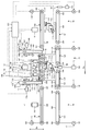
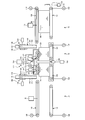
- FIG. 1 is a schematic configuration view showing a cardboard box manufacturing apparatus according to the present embodiment.
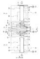
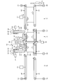
- FIG. 2 is a schematic configuration view showing the cardboard box dividing device of the present embodiment.
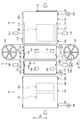
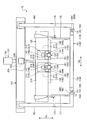
- FIG. 3 is a plan view showing the upper conveyor in the separating apparatus of the carton.
- FIG. 4 is a plan view showing the lower conveyor in the cardboard box dividing device.
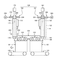
- FIG. 5 is a schematic front view showing a cardboard box cutting apparatus.
- FIG. 6 is a schematic side view showing a cardboard box cutting device.
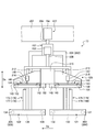
- FIG. 7 is a schematic front view showing a cardboard box positioning apparatus.
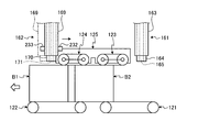
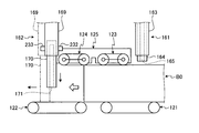
- FIG. 8 is a schematic view showing the operation of the cardboard box positioning device.
- FIG. 9 is a schematic view showing the operation of the cardboard box positioning device.
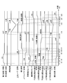
- FIG. 10 is a time chart showing the operation of the cardboard box dividing device.
- FIG. 10 is a time chart showing the operation of the cardboard box dividing device.
- FIG. 11 is a schematic view showing a state of carrying in the connected cardboard box.
- FIG. 12 is a schematic view showing the retracted state of the upper conveyor.
- FIG. 13 is a schematic view showing a positioning state by the positioning member.
- FIG. 14 is a schematic view showing a pressing state by the pressing device.
- FIG. 15 is a schematic view showing a cutting state by processing of a connected cardboard box.
- FIG. 16 is a schematic view showing the raised state of the cardboard box.
- FIG. 17 is a schematic view showing a supported state of the upper conveyor.
- FIG. 18 is a schematic view showing the movement state of the downstream positioning member.
- FIG. 19 is a schematic view showing the unloading state of the cardboard box.
- FIG. 20 is a schematic view showing the unloading state of the cardboard box and the loading state of the linked cardboard box assembly.
- FIG. 21 is a plan view showing a double box sheet before folding.
- FIG. 1 is a schematic configuration view showing a cardboard box manufacturing apparatus according to the present embodiment.
- the transport direction of the cardboard box is Da
- the width direction of the cardboard box in the transport state (horizontal direction orthogonal to the transport direction Da)
- Db the width direction of the cardboard box in the transport state
- Dc the thickness direction of the cardboard box in the transport state
- the cardboard box manufacturing apparatus 10 includes a box making machine 10A and a cardboard box dividing device (hereinafter referred to as a dividing device) 71.
- the box-making machine 10 ⁇ / b> A includes a sheet feeding unit 11, a printing unit 21, a sheet discharging unit 31, a die cutting unit 41, a folding unit 51, and a counter ejector unit 61.
- the paper feed unit 11, the printing unit 21, the paper discharge unit 31, the die cutting unit 41, the folding unit 51, and the counter ejector unit 61 have a linear shape along the conveyance direction Da for conveying the corrugated cardboard sheet S and the corrugated cardboard box B.
- the dividing device 71 is disposed on the downstream side of the counter ejector unit 61 in the conveying direction Da, and the conveying conveyor 81 is disposed between the counter ejector unit 61 and the dividing device 71.
- the box-making machine 10A manufactures the corrugated box B by processing a single-box sheet of the corrugated sheet S.
- the cardboard box manufacturing apparatus 10 manufactures the cardboard box B by processing the double box sheet S0 of the cardboard sheets S.
- the box-making machine 10A processes the double box sheet S0 to manufacture a connected cardboard box B0 in which the two cardboard boxes B are connected along the transport direction Da, and the dividing device 71
- the connected body B0 is cut into two pieces to manufacture a cardboard box B (B1, B2).
- the sheet feeding unit 11 feeds out corrugated sheet S (single box sheet or double box sheet) one by one and sends it to the printing unit 21 at a constant speed.
- the sheet feeding unit 11 includes a table 12, a front pad 13, a supply roller 14, a suction device 15, and a feed roll 16.
- the table 12 is capable of stacking and mounting a large number of corrugated cardboard sheets S, and is supported so as to be movable up and down.
- the front pad 13 can position the front end position of the corrugated cardboard sheet S stacked on the table 12, and a gap is secured between the lower end portion and the table 12 to allow passage of one corrugated sheet S. .
- a plurality of supply rollers 14 are arranged corresponding to the table 12 in the conveyance direction Da of the cardboard sheet S, and when the table 12 is lowered, the supply rollers 14 are at the lowermost position of the stacked cardboard sheets S.
- the cardboard sheet S can be fed forward.
- the suction device 15 sucks the stacked cardboard sheets S downward, that is, toward the table 12 and the supply roller 14 side.
- the feed roll 16 can supply the corrugated sheet S fed by the supply roller 14 to the printing unit 21.
- the printing unit 21 performs multi-color printing (in the present embodiment, four-color printing) on the surface of the cardboard sheet S.
- four printing units 21A, 21B, 21C, and 21D are arranged in series, and printing can be performed on the surface of the cardboard sheet S using four ink colors.
- Each of the printing units 21A, 21B, 21C, and 21D is configured in substantially the same manner, and includes a printing cylinder 22, an ink supply roll (anilox roll) 23, an ink chamber 24, and a receiving roll 25.
- the printing plate 22 is attached to the outer peripheral portion of the printing cylinder 22 and is rotatably provided.
- the ink supply roll 23 is disposed in contact with the printing plate 26 in the vicinity of the printing cylinder 22 and is rotatably provided.
- the ink chamber 24 stores ink, and is provided in the vicinity of the ink supply roll 23.
- the receiving roll 25 nips the corrugated sheet S with the printing cylinder 22 to convey it while applying a predetermined printing pressure, and is provided rotatably opposite to the lower side of the printing cylinder 22 There is.
- each of the printing units 21A, 21B, 21C, and 21D is provided with a pair of upper and lower feed rolls before and after it.
- the paper discharge unit 31 is for subjecting the corrugated cardboard sheet S to crease processing, cut processing, grooving processing, and glue strip processing.
- the sheet discharge unit 31 includes a first ruled line roll 32a, a second ruled line roll 32b, a slitter head 33, a first slotter head 34a, a second slotter head 34b, and a third slotter head 34c. .
- the first ruled-line rolls 32 a are formed in a circular shape, and a plurality of the first ruled-line rolls 32 a are arranged at predetermined intervals in the width direction Db of the corrugated cardboard sheet S.
- the second ruled-line rolls 32 b are formed in a circular shape, and a plurality of the second ruled-line rolls 32 b are arranged at predetermined intervals in the width direction Db of the corrugated cardboard sheet S.
- the first ruled-line roll 32a disposed on the lower side is for subjecting the back surface (lower surface) of the corrugated cardboard sheet S to creased
- the second ruled-line roll 32b disposed on the lower side is similar to the first ruled-line roll 32a
- the back surface (bottom surface) of the corrugated cardboard sheet S is subjected to a crease processing.
- the receiving rolls 35a and 35b are provided so as to be rotatable in synchronization with each other at an upper position facing each other.
- the first slotter heads 34 a are formed in a circular shape, and a plurality of the first slotter heads 34 a are arranged at predetermined intervals in the width direction Db of the cardboard sheet S.
- the first slotter head 34a can perform grooving processing at a predetermined position on the corrugated cardboard sheet S to be conveyed, and can also perform glue margin strip processing.
- the second slotter heads 34 b are formed in a circular shape, and a plurality of the second slotter heads 34 b are arranged at predetermined intervals in the width direction Db of the cardboard sheet S.
- the second slotter head 34b can perform grooving processing at a predetermined position on the corrugated cardboard sheet S to be transported, and can also perform glue margin strip processing.
- the slitter head 33 and the third slotter head 34c are each formed in a circular shape, and a plurality of the slitter heads 33 and the third slotter heads 34c are arranged at predetermined intervals in the width direction Db of the cardboard sheet S.
- the slitter head 33 can cut the end in the width direction Db of the conveyed cardboard sheet S.
- the third slotter head 34c can perform grooving processing at a predetermined position on the corrugated cardboard sheet S to be transported, and can also perform glue margin strip processing.
- the lower blades 36a, 36b, and 36c are synchronously provided rotatably at the lower positions facing each other in the respective slotter heads 34a, 34b, and 34c.
- the die cut portion 41 is for punching the corrugated cardboard sheet S such as a hand hole.
- the die cutting portion 41 has a pair of upper and lower feed pieces 42, an anvil cylinder 43 and a knife cylinder 44.
- the feed piece 42 sandwiches and conveys the corrugated cardboard sheet S from above and below, and is rotatably provided.
- the anvil cylinder 43 and the knife cylinder 44 are each formed in a circular shape, and can be synchronously rotated by a driving device (not shown). In this case, the anvil is mounted on the outer peripheral portion of the anvil cylinder 43, while the blade mounting base (punching blade) is mounted on the knife cylinder 44 at a predetermined position on the outer peripheral portion.
- the folding unit 51 folds the corrugated cardboard sheet S while moving it in the transport direction Da, joins both end portions in the width direction Db, and forms a flat corrugated cardboard box B.
- the folding unit 51 includes an upper conveyance belt 52, lower conveyance belts 53 and 54, and a forming device 55.
- the upper conveyance belt 52 and the lower conveyance belts 53 and 54 sandwich and convey the corrugated cardboard sheet S and the corrugated cardboard box B from above and below.
- the forming device 55 has a pair of left and right forming belts, and the forming belt folds the respective end portions in the width direction Db of the corrugated cardboard sheet S while bending downward.
- the folding unit 51 is provided with a gluing device 56.
- the gluing device 56 has a glue gun, and can paste at a predetermined position on the corrugated cardboard sheet S by discharging the glue at a predetermined timing.
- the counter ejector unit 61 stacks the corrugated cardboard boxes B while counting, sorts them into a predetermined number of batches, and discharges them.
- the counter ejector unit 61 has a hopper device 62.
- the hopper device 62 has a liftable elevator 63 on which the cardboard boxes B are stacked, and the elevator 63 is provided with a front contact plate (not shown) as a shaping means and an angle adjustment plate.
- a carry-out conveyor 64 is provided below the hopper device 62.
- the dividing device 71 is used when the box-making machine 10A processes the double box sheet S0 to manufacture a connected cardboard box assembly B0 in which two cardboard boxes B are connected along the transport direction Da, and is used It can be moved to the position and retracted position. When the box-making machine 10A processes the single box sheet to manufacture the cardboard box B, it moves to the retracted position. On the other hand, when box-making machine 10A processes double box sheet S0 and manufactures corrugated-cardboard box connection body B0, it moves to a use position.
- the dividing device 71 is for manufacturing the cardboard box B (B1, B2) by cutting the cardboard box connected body B0 into two pieces.
- the dividing device 71 includes a loading device 72, a cutting device 73, and a unloading device 74.
- the loading device 72 receives the plurality of connected cardboard box bodies B ⁇ b> 0 transported by the transport conveyor 81 from the counter ejector unit 61 and supplies them to the cutting device 73.
- the cutting device 73 manufactures the cardboard boxes B1 and B2 by dividing the connected cardboard box body B0 into two in the front-rear direction.
- the unloading device 74 receives the cardboard box B1 or B2 divided into two from the cutting device 73 and unloads the cardboard box B1 or B2.
- FIG. 21 is a plan view showing a double box sheet before folding.
- the double box sheet S0 is formed by gluing a corrugated core sheet between the front and back liners, and in advance, two cardboard boxes B are manufactured. It can be cut to size. That is, the double box sheet S0 has a size obtained by connecting the single box sheets S1 and S2.
- four folding lines 301, 302, 303, 304 are formed in the previous process. The folding lines 301, 302, 303, 304 are for folding the flaps when the cardboard box B manufactured by the box making machine 10A is assembled later.
- the double box sheet S ⁇ b> 0 on which the folding lines 301, 302, 303, and 304 are formed is stacked on the table 12 in the sheet feeding unit 11.
- the double box sheet S0 stacked on the table 12 is positioned by the front pad 13, and is lowered by the table 12 and fed out by the plurality of supply rollers 14. Then, the double box sheet S0 is supplied to the printing unit 21 at a predetermined constant speed by the pair of feed rolls 16.
- the ink is supplied from the ink chamber 24 to the surface of the ink supply roll 23, and when the printing cylinder 22 and the ink supply roll 23 rotate, the ink is supplied.
- the ink on the surface of the roll 23 is transferred to the printing plate 26.
- the double box sheet S0 is conveyed between the printing cylinder 22 and the receiving roll 25, the double box sheet S0 is nipped by the printing plate 26 and the receiving roll 25, and the printing pressure is applied here. Is printed on the surface.
- the printed double box sheet S0 is conveyed to the paper discharge unit 31 by the feed roll.
- ruled lines 312, 313, 314, and 315 are formed on the back surface (back liner) side. Also, when the double box sheet S0 passes through the second creased roll 32b, the creased lines 312, 313, 314, 315 are re-formed on the back surface (back liner) side of the corrugated cardboard sheet S as in the first creased roll 32a. .
- the double box sheet S0 on which the ruled lines 312, 313, 314, and 315 are formed passes the slitter head 33, the end portions 321a and 321b are cut at the cutting position 311. Also, when the double box sheet S0 passes the first, second and third slotter heads 34a, 34b and 34c, the grooves 322a, 322b, 322c, 322d, 323a, 323b and 323c are located at the positions of the ruled lines 312, 313 and 314. , 323d, 324a, 324b, 324c, 324d are formed.
- the end portions 325a, 325b, 325c, and 325d are cut at the position of the ruled line 315, whereby the adhesive margin pieces 326a and 326b are formed. Thereafter, as shown in FIG. 1, the double box sheet S0 is conveyed to the die cutting unit 41.
- a hand hole (not shown) is formed.
- hand hole processing is appropriately performed according to the type of double box sheet S0, and a blade mount (punching blade) for carrying out hand hole processing when a hand hole is unnecessary is from the knife cylinder 44 It is removed.
- manual hole processing of the double box sheet S0 by the die cutting portion 41 is omitted, and the double box sheet S0 passes between the rotating anvil cylinder 43 and the knife cylinder 44.
- the gluing device 56 causes the double box sheet S0 to be moved by the upper conveying belt 52 and the lower conveying belts 53 and 54 in the conveying direction Da at the folding unit 51, as shown in FIG. , 326b, and then folded downward by the forming device 55 with the ruled lines 312 and 314 as base points.
- this folding progresses to nearly 180 degrees, the folding force becomes strong, and the adhesive strips 326a, 326b and the end of the double box sheet S0 are pressed against each other to be in close contact with each other, and both ends of the double box sheet S0 are joined. It becomes box connected body B0. Then, the connected cardboard box body B0 is transported to the counter ejector unit 61, as shown in FIG.
- the connected cardboard box body B0 is sent to the hopper device 62, and the tip end portion in the transport direction Da abuts on the front contact plate, and is stacked on the elevator 63 in a state of being shaped by the angle adjusting plate. Then, when the predetermined number of cardboard boxes B are stacked on the elevator 63, the elevator 63 descends, and the predetermined number of cardboard box connected bodies B0 are discharged as one batch by the discharge conveyor 64. Then, a predetermined number of stacked cardboard box connected bodies B 0 are sent to the dividing device 71 by the transport conveyor 81.
- the plurality of connected cardboard box bodies B ⁇ b> 0 transported by the transport conveyor 81 from the counter ejector unit 61 in the dividing device 71 are supplied to the loading device 72.
- the loading device 72 receives a plurality of stacked cardboard box connected bodies B 0 and supplies the same to the cutting device 73.
- the cutting device 73 divides the plurality of connected cardboard box bodies B0 along the width direction Db at the position of the two-dot chain line 331 (see FIG. 21) to divide into two in front and back, thereby manufacturing cardboard boxes B1 and B2.
- the unloading device 74 receives and unloads the cardboard boxes B1 and B2 divided into two by the cutting device 73.
- FIG. 2 is a schematic block diagram showing the cardboard box dividing device of the present embodiment
- FIG. 3 is a plan view showing the upper conveyor in the cardboard box dividing device
- FIG. 4 is the lower conveyor in the cardboard box dividing device. It is a top view.
- the dividing device 71 includes a loading device 72, a cutting device 73, and a unloading device 74.
- the carry-in device 72, the cutting device 73, and the carry-out device 74 are disposed along the transport direction Da of the connected cardboard box body B0 and the loaded cardboard box B (B1, B2).
- the loading device 72 supplies a plurality of stacked cardboard box connected bodies B0 to the cutting device 73, and includes a loading lower conveyor 101 and a loading upper conveyor 102.
- the lower loading conveyor 101 and the upper loading conveyor 102 are arranged to face each other in the thickness direction Dc of the corrugated cardboard sheet S at a predetermined interval.
- the lengths of the lower conveying conveyor 101 and the upper conveying conveyor 102 in the conveying direction Da are substantially the same, but the length in the width direction Db in the upper conveying conveyor 102 is shorter than the length in the width direction Db in the lower conveying conveyor 101 It has become.
- the lower conveying conveyor 101 is configured by winding an endless conveyance belt 105 between the drive roller 103 and the driven roller 104.
- the carry-in upper conveyor 102 is configured such that an endless conveyance belt 108 is wound around the driving roller 106 and the driven roller 107.
- a plurality of rollers are disposed between the drive rollers 103 and 106 and the driven rollers 104 and 107, respectively, so that the conveying belts 105 and 108 become loose. Is prevented.
- the loading lower conveyor 101 is provided with a drive motor 109 capable of driving and rotating the drive roller 103.
- the carry-in upper conveyor 102 is provided with a drive motor 110 capable of driving and rotating the drive roller 106.
- the upper carry-in conveyor 102 is vertically movably supported by a carry-in upper conveyor moving device 111.
- the loading device 72 has a left side alignment device 112 and a right side alignment device 113.
- the left side alignment device 112 and the right side alignment device 113 are disposed to face each other in the width direction Db.
- the left side aligning device 112 and the right side aligning device 113 are configured by aligning plates 114 and 115 opposed in the width direction Db, and drive cylinders 116 and 117 moving the aligning plates 114 and 115 along the width direction Db. It is done.
- the positions of the left side aligning device 112 and the right side aligning device 113 can be adjusted in the width direction Db according to the width dimension of the connected cardboard box connected body B0.
- the loading device 72 has an open / close door 118.
- the open / close door 118 has a plate shape disposed along the width direction Db and the thickness direction Dc on the upstream side of the carry-in lower conveyor 101 in the transport direction Da.
- the open / close door 118 is movable by the drive cylinder 119 along the thickness direction Dc, and is moved to a closed position located above the carry-in lower conveyor 101 and an open position located below the carry-in lower conveyor 101.
- the cutting device 73 is configured to cut the corrugated cardboard box connected laminate in which a plurality of corrugated cardboard box connected bodies B0 are stacked in the thickness direction Dc along the width direction Db and divide it into two corrugated cardboard boxes B1 and B2.
- the cutting device 73 includes an inlet-side lower conveyor 121 and an outlet-side lower conveyor 122 as a lower conveyor, an inlet-side upper conveyor 123 and an outlet-side upper conveyor 124 as an upper conveyor, a pressing device 125, a cutting blade 126, and raising and lowering.
- a device 127 and a positioning device 128 are included.
- the inlet-side lower conveyor 121 and the outlet-side lower conveyor 122 stack and convey a plurality of connected cardboard box bodies B0, and the length in the width direction Db is the same as the carry-in lower conveyor 101, and the length in the conveying direction Da. Is about half each.
- the inlet-side lower conveyor 121 and the outlet-side lower conveyor 122 have the same length in the width direction Db, and have the same length in the transport direction Da.
- the inlet-side lower conveyor 121 and the outlet-side lower conveyor 122 are disposed with a predetermined gap in the transport direction Da.
- the inlet-side lower conveyor 121 is configured such that an endless conveyance belt 133 is wound around a driving roller 131 and a driven roller 132.
- the outlet-side lower conveyor 122 is configured such that an endless conveyance belt 136 is wound around the driving roller 134 and the driven roller 135.
- the inlet-side lower conveyor 121 and the outlet-side lower conveyor 122 are provided with a plurality of rollers between the drive rollers 131 and 134 and the driven rollers 132 and 135, respectively, to convey the transfer belts 133 and 136. Slack is prevented.
- the inlet-side lower conveyor 121 is provided with a drive motor 137 capable of driving and rotating the drive roller 131.
- the outlet-side lower conveyor 122 is provided with a drive motor 138 capable of driving and rotating the drive roller 134.
- the inlet-side upper conveyor 123 and the outlet-side upper conveyor 124 support and transport the upper portions of the plurality of connected cardboard box bodies B0 stacked on the inlet-side lower conveyor 121 and the outlet-side lower conveyor 122, and are in the width direction
- the length of Db is shorter than the inlet-side lower conveyor 121 and the outlet-side lower conveyor 122, and the length of the conveyance direction Da is short, and it is composed of a plurality of conveyors (two in the present embodiment).
- the inlet-side upper conveyor 123 and the outlet-side upper conveyor 124 are disposed with a predetermined gap in the transport direction Da.
- the inlet-side upper conveyor 123 is disposed to face the upper side of the inlet-side lower conveyor 121, and an endless conveyance belt 141 is wound around the driving roller 139 and the driven roller 140 and configured.
- the outlet-side upper conveyor 124 is disposed to face the upper side of the outlet-side lower conveyor 122, and an endless transport belt 144 is wound around the drive roller 142 and the driven roller 143.
- two conveyors are juxtaposed with a predetermined interval in the width direction Db.
- the inlet upper conveyor 123 and the outlet upper conveyor 124 on the left side with respect to the transport direction Da are provided with drive motors 145 capable of driving and rotating the drive rollers 139 and 142, and the inlet on the right side with respect to the transport direction Da.
- the side upper conveyor 123 and the outlet side upper conveyor 124 are provided with a drive motor 146 capable of driving and rotating the drive rollers 139 and 142.
- the inlet-side upper conveyor 123 and the outlet-side upper conveyor 124 are vertically movably supported by the inlet-side upper conveyor moving device 147 and the outlet-side upper conveyor moving device 148.
- the pressing device 125 presses a plurality of connected cardboard box bodies B ⁇ b> 0 stacked on the inlet lower conveyor 121 and the outlet lower conveyor 122 from above.
- the pressing device 125 has width direction pressing members 149 and 150 along the width direction Db above the inlet-side lower conveyor 121 and the outlet-side lower conveyor 122, and a plurality of transport direction pressing members 151 and 152 along the transport direction Da. doing.
- the width direction pressing member 149 is disposed downstream of the inlet-side upper conveyor 123, and a plurality of conveyance direction pressing members 151 extend from the width direction pressing member 149 to the upstream side in the conveyance direction Da.
- the width direction pressing member 150 is disposed on the upstream side of the outlet-side upper conveyor 124, and a plurality of conveyance direction pressing members 152 extend from the width direction pressing member 150 to the downstream side in the conveyance direction Da.
- the pressing device 125 is vertically movably supported by the pressing drive device 153.
- the cutting blade 126 is disposed along the width direction Db between the inlet-side lower conveyor 121 and the outlet-side lower conveyor 122, and a blade portion is formed along the upper portion.
- the cutting blade 126 has an endless shape, and is wound around and supported by a drive pulley 154 and a driven pulley 155 disposed on both sides in the width direction Db of the inlet-side lower conveyor 121.
- the cutting blade driving device 156 is capable of driving and rotating the driving pulley 154, and moves the cutting blade 126 between the inlet-side lower conveyor 121 and the outlet-side lower conveyor 122 in the width direction Db by rotation of the driving pulley 154. can do.
- the cutting blade 126 is at a cutting position between the inlet-side lower conveyor 121 and the outlet-side lower conveyor 122, and only moves between the inlet-side lower conveyor 121 and the carry-in lower conveyor 101.
- the lifting device 127 moves the plurality of cardboard box connected bodies B0 on the inlet-side lower conveyor 121 and the outlet-side lower conveyor 122 relative to the cutting blade 126 along the vertical direction.
- the lifting device 127 makes the cutting blade 126 unmovable in the vertical direction, and presses the inlet-side lower conveyor 121 and the outlet-side lower conveyor 122, the inlet-side upper conveyor 123, and the outlet-side upper conveyor 124
- the device 125 can be moved up and down along the vertical direction.
- the inlet-side lower conveyor 121, the outlet-side lower conveyor 122, the inlet-side upper conveyor 123, the outlet-side upper conveyor 124, and the pressing device 125 are supported by a lift platform 157.
- the elevation driving device 158 is capable of moving up and down the elevator platform 157 along the vertical direction, and the elevator platform 157 moves up and down, whereby the inlet lower conveyor 121 and the outlet lower conveyor 122, the inlet upper conveyor 123 and the outlet upper The conveyor 124 and the pressing device 125 move up and down. That is, when the elevator platform 157 descends, a plurality of connected cardboard box bodies B0 supported by the inlet-side lower conveyor 121, the outlet-side lower conveyor 122, the inlet-side upper conveyor 123, the outlet-side upper conveyor 124, and the pressing device 125 It descends, and the plurality of connected cardboard box connectors B 0 are cut by the cutting blade 126.
- the positioning device 128 performs positioning in the transport direction Da of the plurality of connected cardboard box bodies B ⁇ b> 0 supplied onto the inlet-side lower conveyor 121 and the outlet-side lower conveyor 122.
- the positioning device 128 has two upstream positioning members 161 and two downstream positioning members 162.
- the upstream positioning member 161 is movable upstream of the inlet-side lower conveyor 121 along the transport direction Da and the thickness direction Dc of the connected cardboard box B0.
- the downstream positioning member 162 is movable at a downstream portion of the outlet-side lower conveyor 122 along the transport direction Da and the thickness direction Dc of the connected carton B0.
- the upstream positioning member 161 and the downstream positioning member 162 can be moved independently by the positioning drive device.
- the upstream positioning member 161 has a telescopic structure in which the support cylinder 163, the outer cylinder 164, and the inner cylinder 165 are fitted to each other.
- the first drive device 166 can raise and lower the outer cylinder 164 along the thickness direction Dc with respect to the fixed support cylinder 163, and the second drive device 167 thickens the inner cylinder 165 with respect to the outer cylinder 164. It can move up and down along the vertical direction Dc.
- the third drive device 168 can move the support cylinder 163 together with the outer cylinder 164 and the inner cylinder 165 along the transport direction Da.
- the downstream positioning member 162 has a telescopic structure in which the support cylinder 169, the outer cylinder 170, and the inner cylinder 171 are fitted to each other.
- the first drive device 172 can raise and lower the outer cylinder 170 along the thickness direction Dc with respect to the fixed support cylinder 169, and the second drive device 173 thickens the inner cylinder 171 with respect to the outer cylinder 170. It can move up and down along the vertical direction Dc. Further, the third drive device 174 can move the support cylinder 169 together with the outer cylinder 170 and the inner cylinder 171 along the transport direction Da.
- the upstream positioning member 161 has a telescopic structure in which the support cylinder 163, the outer cylinder 164, and the inner cylinder 165 are fitted to each other, the width of the outer cylinder 164 in the conveyance direction Da is the conveyance direction Da in the support cylinder 163
- the width in the conveying direction Da of the inner cylinder 165 is narrower than the width in the conveying direction Da of the outer cylinder 164.
- the downstream positioning member 162 has a telescopic structure in which the support cylinder 169, the outer cylinder 170, and the inner cylinder 171 are fitted to each other, the width of the outer cylinder 170 in the transport direction Da is the support cylinder.
- the width in the conveyance direction Da in the inner cylinder 171 is narrower than the width in the conveyance direction Da in 169, and the width in the conveyance direction Da in the outer cylinder 170 is narrower.
- the positioning drive device is constituted by the respective drive devices 166, 167, 168, 172, 173, 174.
- the cutting device 73 has a left side alignment device 175 and a right side alignment device 176.
- the left side aligning device 175 and the right side aligning device 176 are disposed to face each other in the width direction Db.
- the left side aligning device 175 and the right side aligning device 176 are configured by aligning plates 177 and 178 facing each other in the width direction Db, and drive cylinders 179 and 180 moving the aligning plates 177 and 178 along the width direction Db. It is done.
- the left side aligning device 175 is disposed to the side of the inlet side lower conveyor 121 and the outlet side lower conveyor 122, and the aligning plate 177 extends below the inlet side lower conveyor 121 and the outlet side lower conveyor 122 It is done.
- the right side aligning device 176 is disposed on the inlet side lower conveyor 121 and above the outlet side lower conveyor 122, and the aligning plate 178 is extended to the upper surfaces of the inlet side lower conveyor 121 and the outlet side lower conveyor 122 . Therefore, in the left side aligning device 175, no gap is generated between the lower end portion of the aligning plate 177 and the upper surface of the lower conveyors 121 and 122, so when the aligning plates 177 and 178 move so as to approach each other, A plurality of cardboard box connected bodies B 0 stacked on the lower conveyors 121 and 122 can be aligned with the aligning plate 177 to properly align the paper in the width direction Db. Further, the position of the right side aligning device 176 can be adjusted in the width direction Db in accordance with the width dimension of the connected cardboard box body B0 to be processed.
- the unloading device 74 receives the cardboard boxes B1 and B2 which are cut by the cutting device 73 and stacked in plurality and is unloaded to the outside, and includes a unloading lower conveyor 181 and an unloading upper conveyor 182.
- the lower unloading conveyor 181 and the upper unloading conveyor 182 are arranged to face each other in the thickness direction Dc of the corrugated cardboard sheet S at a predetermined interval.
- the lengths of the lower delivery conveyor 181 and the upper delivery conveyor 182 in the transport direction Da are substantially the same, but the length in the width direction Db in the upper delivery conveyor 182 is shorter than the length in the width direction Db in the lower delivery conveyor 181 It has become.
- the lower transport conveyor 181 is configured by winding an endless transport belt 185 between the drive roller 183 and the driven roller 184.
- the carry-out upper conveyor 182 is configured by winding an endless conveyance belt 188 between the drive roller 186 and the driven roller 187.
- the plurality of rollers are disposed between the drive rollers 183 and 186 and the driven rollers 184 and 187 on the lower conveyor 181 for conveyance and the upper conveyor 182, respectively, so that the conveying belts 185 and 188 are slackened. Is prevented.
- the lower unloading conveyor 181 is provided with a drive motor 189 capable of driving and rotating the drive roller 183.
- the carry-out upper conveyor 182 is provided with a drive motor 190 capable of driving and rotating the drive roller 186. Further, the carry-out upper conveyor 182 is supported by the carry-out upper conveyor moving device 191 so as to be vertically movable.
- FIG. 5 is a front schematic view showing a cardboard box cutting apparatus
- FIG. 6 is a side schematic view showing a cardboard box cutting apparatus.
- the lifting platform 157 has a beam shape along the horizontal direction, and a frame in the inlet-side lower conveyor 121 and the outlet-side lower conveyor 122 via the pair of left and right connection members 201 and 202. 203, 204, 205 and 206 are linked.
- the lift drive unit 158 is provided on the apparatus frame 207, and the tip of the drive rod 208 is connected to the lift platform 157.
- the lifting table 157 is provided with a pressing drive device 153, and the tip end portion of the driving rod 209 is connected to the support frame 210 of the pressing device 125.
- the support frame 210 is disposed along the width direction Db, two mounting frames 211 are fixed on the upstream side in the transport direction Da, and two mounting frames 212 are fixed on the downstream side.
- the mounting frame 211 has the width direction pressing member 149 and the conveyance direction pressing member 151 fixed to the lower surface, and the mounting frame 212 has the width direction pressing member 150 and the conveyance direction pressing member 152 fixed to the lower surface.
- the left side aligning device 175 and the right side aligning device 176 are supported by the support frame 210, and the respective aligning plates 177 and 178 hang downward.
- the aligning plate 178 is movable in the width direction Db.
- the inlet-side upper conveyor 123 and the outlet-side upper conveyor 124 are disposed inside the pressing members 149, 150, 151, 152.
- the inlet-side upper conveyor 123 and the outlet-side upper conveyor 124 are disposed inside the mounting frames 211 and 212 that support the pressing members 149, 150, 151 and 152.
- the mounting frames 211 and 212 are provided with space portions 213 and 214 that open downward.
- the inlet-side upper conveyor moving device 147 is fixed to the space portion 213, and the inlet-side upper conveyor 123 is connected to the tip of the drive rod 215.
- the outlet-side upper conveyor moving device 148 is fixed to the space 214, and the outlet-side upper conveyor 124 is connected to the tip of the drive rod 216.
- the drive rod 208 can expand and contract, and can lift and lower the lifting platform 157, and the inlet lower conveyor 121 and the outlet lower conveyor 122 supported by the lifting platform 157 and the inlet upper conveyor 123 and the outlet side upper conveyor 124 and the pressing device 125 can be raised and lowered.
- the press drive device 153 the drive rod 209 expands and contracts, and the press device 125, the inlet side upper conveyor 123, and the outlet side upper conveyor 124 can be moved up and down with respect to the elevator platform 157.
- the conveyor moving devices 147 and 148 are driven, the drive rods 215 and 216 expand and contract, and the inlet-side upper conveyor 123 and the outlet-side upper conveyor 124 can be moved up and down with respect to the pressing device 125.
- the loading device 72, the cutting device 73, and the unloading device 74 that constitute the dividing device 71 can be operationally controlled by the control device 231.
- the control device 231 can drive and control the drive motors 109 and 110, the carry-in upper conveyor moving device 111, and the drive cylinders 116, 117, and 119 of the loading device 72.
- the control device 231 includes drive motors 137, 138, 145 and 146 of the cutting device 73, conveyor moving devices 147 and 148, a press drive device 153, an elevation drive device 158, and drive devices 166, 167, 168, 172, 173 and 174. Drive control is possible.
- the control device 231 can drive and control the drive motors 189 and 190 of the unloading device 74 and the unloading upper conveyor moving device 191.
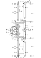
- FIG. 7 is a schematic front view showing a cardboard box positioning device
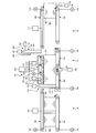
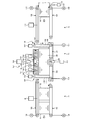
- FIGS. 8 and 9 are schematic diagrams showing the operation of the cardboard box positioning device.
- the first drive device 166 can raise and lower the outer cylinder 164 with respect to the support cylinder 163 by the upstream positioning member 161, and the second drive device 167 can move relative to the outer cylinder 164.
- the third cylinder 168 can move up and down, and the third drive device 168 can move the support cylinder 163, the outer cylinder 164, and the inner cylinder 165 along the transport direction Da.
- the first drive device 166 and the second drive device 167 are constituted by, for example, an air cylinder, and the third drive device 168 is fixed to the screw shaft 221 and the support cylinder 163, and the screw shaft 221 is screwed together.
- a moving body 222 and a motor 223 for driving and rotating a screw shaft 221 are provided.
- the first drive device 172 can raise and lower the outer cylinder 170 with respect to the support cylinder 169 by the downstream positioning member 162, and the second drive device 173 raises and lowers the inner cylinder 171 with respect to the outer cylinder 170.
- the third drive unit 174 is capable of moving the support cylinder 169, the outer cylinder 170, and the inner cylinder 171 in the transport direction Da.
- the first drive device 172 and the second drive device 173 are configured by, for example, an air cylinder, and the third drive device 174 is fixed to the screw shaft 224 and the support cylinder 169 and the screw shaft 224 is screwed together.
- a moving body 225 and a motor 226 for driving and rotating a screw shaft 224 are provided.
- the positioning drive device of the present invention is each drive device 166, 167, 168, 172, 173, 174, and the upstream positioning member 161 and the downstream positioning member 162 can be moved independently.
- control device 231 drives and controls the first drive devices 166 and 172 and the second drive devices 167 and 173 as the elevation platform 157 moves up and down, thereby the outer cylinders 164 and 170 with respect to the support cylinders 163 and 169.
- the inner cylinder 165,171 is operated along thickness direction Dc.
- the control device 231 controls the drive of the third drive device 174 after the elevator board 157, the upstream positioning member 161, and the downstream positioning member 162 are lifted by cutting the plurality of connected cardboard box assemblies B0 back and forth by the cutting blade 126. By doing this, the downstream positioning member 162 is moved to the upstream side in the transport direction Da by a predetermined distance. Specifically, when the upstream positioning member 161 and the downstream positioning member 162 are in the raised position, the control device 231 causes the cut cardboard boxes B1 and B2 to be downstream by the inlet-side lower conveyor 121 and the outlet-side lower conveyor 122 By driving and controlling the third driving device 174 while passing under the positioning member 162, the downstream positioning member 162 is moved upstream by a predetermined distance in the transport direction Da.
- control device 231 drives and controls the first drive device 172 after the cut cardboard boxes B1 and B2 pass under the downstream positioning member 162 by the inlet lower conveyor 121 and the outlet lower conveyor 122. Then, by lowering the outer cylinder 170 and the inner cylinder 171 and controlling the drive of the third driving device 174, the downstream positioning member 162 is moved downstream by a predetermined distance in the transport direction Da.
- the downstream side positioning member 162 is provided with an arrival detection sensor 232 for detecting the arrival of the connected cardboard box B0 (the tip in the transport direction Da) on the support cylinder 169, and detects the passage of the cardboard boxes B1 and B2.
- a passage detection sensor 233 is provided.
- the arrival detection sensor 232 and the passage detection sensor 233 output the detection result to the control device 231. Therefore, when the arrival detection sensor 232 detects the arrival of the cardboard box connected body B0, the control device 231 stops the operation of the inlet-side lower conveyor 121, the outlet-side lower conveyor 122, the inlet-side upper conveyor 123, and the outlet-side upper conveyor 124. Do. Further, when the passage detection sensor 233 detects the passage of the cardboard boxes B1 and B2 below the downstream positioning member 162, the control device 231 starts lowering the outer cylinder 170 and the inner cylinder 171 in the downstream positioning member 162.
- the passage detection sensor 233 detects the passage of the cardboard boxes B1 and B2 below the downstream positioning member 162.
- the downstream positioning member 162 indicated by a two-dot chain line at 8 is moved upstream by a predetermined distance (for example, a position indicated by a solid line in FIG. 8) in the transport direction Da.
- a predetermined distance for example, a position indicated by a solid line in FIG. 8
- the outer cylinder 170 is held inside the outer cylinder 170
- the cylinder 170 is lowered, and the downstream positioning member 162 is moved downstream in the transport direction Da by a predetermined distance (for example, a position indicated by a two-dot chain line in FIG. 9).
- FIG. 10 is a time chart showing the operation of the cardboard box dividing apparatus
- FIG. 11 is a schematic view showing the loading state of the connected cardboard box body
- FIG. 12 is a schematic view showing the retracted state of the upper conveyor
- FIG. FIG. 14 is a schematic view showing a pressing state by a pressing device
- FIG. 15 is a schematic view showing a cutting state by processing of a connected cardboard box body
- FIG. 16 is an elevation of the cardboard box.
- FIG. 17 is a schematic view showing the support state of the upper conveyor
- FIG. 18 is a schematic view showing the movement state of the downstream positioning member
- FIG. 19 is a schematic view showing the unloading state of the cardboard box.
- FIG. 20 is a schematic view showing the unloading state of the cardboard box and the loading state of the linked cardboard box assembly.
- unloading of the cut cardboard boxes B1 and B2 is performed until time t5.
- the lower unloading conveyor 181 and the upper unloading conveyor 182 in the unloading device 74 stop the driving and rotating of the drive motors 189 and 190, and completely stop at time t6.
- the arrival detection sensor 232 is turned off from time t2 to t3, and the passage detection sensor 233 is turned off from time t3 to t4.
- the lower loading conveyor 101 and the upper loading conveyor 102 in the loading device 72 start operation by driving and rotating the drive motors 109 and 110. Further, the inlet side lower conveyor 121, the outlet side lower conveyor 122, the inlet side upper conveyor 123, and the outlet side upper conveyor 124 in the cutting device 73 are in operation by the drive rotation of the drive motors 137, 138, 145, 146. Therefore, the connected cardboard box body B0 is carried in by the carry-in device 72 and supplied to the cutting device 73.
- the first drive device 172 is driven to move downward while holding the inner cylinder 171 inside the outer cylinder 170 of the downstream positioning member 162, and from time t4 to t6, the third drive device 174 is driven, the downstream positioning member 162 moves to the downstream side in the transport direction Da, and stops at the paper alignment position.
- the arrival detection sensor 232 detects the tip of the connected cardboard box body B0, and from time t6 to t7. Over time, it will be ON. Then, the lower loading conveyor 101 and the upper loading conveyor 102 in the loading device 72 stop operation from time t7 to t8. In addition, the lower inlet conveyor 121 and the lower outlet conveyor 122, the upper inlet conveyor 123, and the upper upper conveyor 124 in the cutting device 73 stop operating from time t8 to t9.
- the left side aligning device 175 and the right side aligning device 176 operate (paper alignment execution) from time t11 to t12, and the inlet side lower conveyor 121 and the outlet side lower conveyor 122 Paper alignment in the width direction Db of a plurality of cardboard box connected bodies B0 stacked on top is performed.
- the outer cylinder 164 moves to the downstream side in the transport direction Da from time t13 to t14, and along with the outer cylinder 170 of the downstream positioning member 162, the inlet lower conveyor 121 and the outlet lower conveyor 122 Paper alignment in the transport direction Da is performed on a plurality of connected cardboard box bodies B0 stacked on one another.
- the upstream positioning member 161 and the downstream positioning member 162 exert a downward stress on the inner cylinders 165 and 171 from time t16 to time t17.
- the pressing device 125 descends the width direction pressing members 149 and 150 and the conveyance direction pressing members 151 and 152 from time t15 to time t16 to stack the plurality of inlet side lower conveyors 121 and outlet side lower conveyors 122. Press and support the cardboard box connected body B0.
- a plurality of connected cardboard boxes B0 stacked on the inlet-side lower conveyor 121 and the outlet-side lower conveyor 122 includes a left side aligning device 175 and a right side aligning device 176, and an upstream positioning member 161 and a downstream positioning member 162.
- the lifting device 127 When supported by the width direction pressing members 149 and 150 and the conveyance direction pressing members 151 and 152, as shown in FIGS. 10 and 15, the lifting device 127 operates from time t16 to time t17 to connect a plurality of cardboard boxes Lower body B0. Then, the cutting blade 126 is relatively lifted by the descending operation of the plurality of connected cardboard box bodies B0, and the plurality of connected cardboard box bodies B0 are cut along the width direction Db to form a plurality of cardboard boxes B1 and B2.
- the upstream positioning member 161 and the downstream positioning member 162 have a plurality of inner cylinders 165, 171 having a narrower width than the outer cylinders 164, 170, so that the plurality of A clearance is secured between the connected cardboard box assembly B0.
- the plurality of connected cardboard boxes B0 are cut by the cutting blade 126, the plurality of cardboard boxes B1 can slightly move toward the downstream side in the transport direction Da within the range of the gap, and the plurality of cardboard boxes B2 can move slightly in the range of the clearance toward the upstream side in the transport direction Da.
- the lifting device 127 operates from time t17 to time t20 and the plurality of cardboard boxes B1 and B1 Raise B2.
- the left side justification device 175 and the right side justification device 176 operate (cancel the paper alignment) from time t17 to t18, and move to the standby position where they are separated from the cardboard boxes B1 and B2.
- the upstream positioning member 161 and the downstream positioning member 162 rise from time t17 to t20.
- the upstream positioning member 161 moves upstream in the transport direction Da from time t17 to t21.
- the pressing device 125 performs the width direction pressing members 149 and 150 and the conveyance direction pressing members 151 and 152 from time t18 to t21.
- the inlet-side upper conveyor 123 and the outlet-side upper conveyor 124 descend from time t18 to t19 and support the upper portions of the cardboard boxes B1 and B2. Also, as shown in FIGS.
- the downstream positioning member 162 moves to the standby position on the upstream side in the transport direction Da from time t22 to t23.
- the passage detection sensor 233 detects the front end of the cardboard box B1 whose unloading has been started, and is turned on from time t21 to time t22.
- the plurality of cardboard boxes B1 and B2 are transferred from the cutting device 73 to the unloading device 74, and as shown in FIGS. 10 and 20, the unloading device 74 transfers the plurality of cardboard boxes B1. , B2 are carried out. Thereafter, the downstream positioning member 162 is lowered.
- the lower conveyors 121 and 122 that stack and convey the plurality of connected cardboard box bodies B0 and the connected cardboard box bodies B0 at the upstream portion of the lower conveyors 121 and 122
- the upstream positioning member 161 movable along the conveying direction Da and the thickness direction Dc of the sheet, and the downstream portion of the lower conveyors 121 and 122 are movable along the conveying direction Da and the thickness direction Dc of the connected cardboard box B0.
- the pressing device 125 for pressing is disposed along the width direction Db of the connected cardboard box body B0 and stacked on the lower conveyors 121 and 122.
- a plurality of stacked corrugated cardboard box connected bodies B0 are mounted on the lower conveyors 121 and 122, and the corrugated cardboard boxes by the upstream positioning member 161 and the downstream positioning member 162 at predetermined cutting positions stopped on the lower conveyors 121 and 122.
- the connecting body B0 is positioned in the transport direction Da, it is pressed from above by the pressing device 125, and in this state, a plurality of connected cardboard box connectors B0 and the cutting blade 126 are moved relative to each other by the lifting device 127.
- the stacked cardboard box connected body B0 is cut by the cutting blade 126 and divided.
- a plurality of connected cardboard boxes B0 are unstable in the stacked state and may be shifted in the transport direction Da when stopped at the cutting position, but the plurality of connected cardboard boxes B0 stop at the cutting position Since the positioning is performed by the upstream positioning member 161 and the downstream positioning member 162 after that, the plurality of connected cardboard box connectors B0 can be cut with high accuracy. At this time, since the upstream positioning member 161 and the downstream positioning member 162 can be moved independently by the positioning drive device, the upstream positioning member 161 and the downstream positioning can be performed according to the cut state of the connected cardboard box connector B0. The members 162 can be moved separately. As a result, by shortening the positioning process time at the cutting position of the connected cardboard box body B0, it is possible to speed up the cutting operation and improve production efficiency.
- the lifting device 127 a lifting platform 157 supporting the lower conveyors 121 and 122 and the pressing device 125, and a lifting drive device 158 lifting the lifting platform 157 are provided.
- the lower positioning member 161 moves the upstream positioning member 161 and the downstream positioning member 162 along the thickness direction Dc of the connected cardboard box body B0 as the lifting platform 157 moves up and down. Therefore, the lifting and lowering operations of the lower conveyors 121 and 122 by the lifting and lowering drive unit 158 and the lifting and lowering operations of the upstream positioning member 161 and the downstream positioning member 162 by the positioning drive can be independently performed.
- the downstream positioning member 162 can position the corrugated cardboard box connected body B0 and the corrugated cardboard boxes B1 and B2 after cutting, and stabilize the plurality of corrugated cardboard box connected bodies B0 and the corrugated cardboard boxes B1 and B2 with a simple configuration. Support.
- the upstream positioning member 161 and the downstream positioning member 162 are configured as telescopic structures in which the support cylinders 163 and 169, the outer cylinders 164 and 170, and the inner cylinders 165 and 171 are fitted to each other.
- the positioning drive device is capable of moving the support cylinders 163 and 169, the outer cylinders 164 and 170, and the inner cylinders 165 and 171 along the transport direction Da of the connected cardboard box body B0, and for the support cylinders 163 and 169.
- the outer cylinders 164 and 170 and the inner cylinders 165 and 171 can be moved along the thickness direction Dc of the connected cardboard box body B0.
- the upstream positioning member 161 and the downstream positioning member 162 into a telescopic structure, downsizing of the device can be achieved, and the upstream positioning member 161 and the downstream positioning member 162 can be connected to a cardboard box by the positioning drive device.
- the positioning drive device By being movable along the transport direction Da and the thickness direction Dc of the body B0, positioning with respect to the cardboard box connected body B0 can be smoothly performed.
- the upstream positioning member 161 and the downstream positioning member 162 have a width in the conveying direction Da of the inner cylinders 165 and 171 smaller than the width in the conveying direction Da of the outer cylinders 164 and 170. It is set. Therefore, when the plurality of connected cardboard box bodies B0 are lowered, the upstream positioning member 161 and the downstream positioning member 162 have the narrow inner cylinders 165 and 171 lowered. , 171 are secured. On the other hand, when the plurality of connected cardboard box bodies B0 are lowered and cut by the cutting blade 126, the plurality of cut cardboard boxes B1 and B2 slightly move downstream and upstream in the transport direction Da.
- the plurality of cardboard boxes B1 and B2 after cutting move within the range of the gap, and the upstream positioning member 161 and the downstream positioning member 162 inhibit the cutting operation of the plurality of linked cardboard boxes B0. Therefore, the plurality of cardboard boxes B1 and B2 can be properly supported.
- the downstream positioning member 162 is lifted after cutting the plurality of linked cardboard boxes B0 back and forth by the cutting blade 126, and then the downstream positioning member 162 is moved upstream in the transport direction Da. Is moved by a predetermined distance. Therefore, preparation for lowering the downstream positioning member 162 can be made early while preventing the downstream positioning member 162 from contacting the cardboard box B1.
- the downstream positioning member 162 when the downstream positioning member 162 is in the raised position, the cut cardboard boxes B1 and B2 pass below the downstream positioning member 162 by the lower conveyors 121 and 122, The downstream positioning member 162 is moved upstream by a predetermined distance in the transport direction Da. Therefore, while the contact between the downstream positioning member 162 and the cardboard box B1 is reliably prevented, preparation for lowering the downstream positioning member 161 can be performed early.
- the downstream positioning member 162 is lowered and the transport direction Da is lowered. It is moved by a predetermined distance to the downstream side. Therefore, the downstream positioning member 162 can be moved to the positioning position on the downstream side of the connected cardboard box assembly B0 at an early stage while preventing contact between the downstream positioning member 162 and the cardboard boxes B1, B2, Efficiency can be improved.
- the paper feed unit 11 for supplying the double box sheet S0, and the discharge for performing the grooving process on the surface of the double box sheet S0.
- the stacking unit 51 forms a corrugated box connected body B0 by folding the double box sheet S0 and joining the end portions, and stacking the corrugated box connected body B0 after counting and discharging the predetermined number.
- a counter ejector unit 61 and a dividing device 71 for cutting and dividing the connected cardboard box body B0 along a width direction Db intersecting the transport direction Da are provided.
- the double-box sheet S0 from the paper supply unit 11 is subjected to crease processing and grooving processing by the discharge unit 31, and is folded by the folding unit 51 and the end portions are joined to form the connected cardboard box body B0.
- the boxes are stacked while being counted by the counter ejector unit 61, and are cut by the dividing device 71 to manufacture the cardboard boxes B1 and B2.
- the plurality of cardboard box connected bodies B0 are positioned by the upstream positioning member 161 and the downstream side positioning member 162 after stopping at the cutting position, so that the plurality of cardboard box connected bodies B0 can be cut with high accuracy. .
- the upstream positioning member 161 and the downstream positioning member 162 can be moved independently by the positioning drive device, the upstream positioning member 161 and the downstream positioning can be performed according to the cut state of the connected cardboard box connector B0.
- the members 162 can be moved separately. As a result, by shortening the positioning process time at the cutting position of the connected cardboard box body B0, it is possible to speed up the cutting operation and improve production efficiency.
- the box-making machine 10A processes the double box sheet S0 to manufacture the connected cardboard box body B0, and the dividing device 71 cuts the connected cardboard box body B0 to process the cardboard boxes B1 and B2.
- a box-making machine may process triple box sheets to produce a connected cardboard box, and a dividing device may cut the connected cardboard box into three pieces to produce a cardboard box.
- the sizes of the manufactured cardboard boxes may be the same or different. That is, by shifting the stopping position (cutting position) of the connected cardboard box body B0 in the cutting device 73 in the transport direction Da, it is possible to manufacture the connected cardboard box body B0 of different size.
- the connected cardboard box body B0 is cut by lowering the connected cardboard box body B0 with respect to the cutting blade 126.
- the connected cardboard box body B0 is lifted with respect to the cutting blade 126
- the cardboard box connected body B0 may be cut, or the cardboard box connected body B0 may be cut by raising or lowering the cutting blade 126 with respect to the cardboard box connected body B0.
- the inlet-side lower conveyor 121 and the outlet-side lower conveyor 122 are provided as the lower conveyor, and the inlet-side upper conveyor 123 and the outlet-side upper conveyor 124 are provided as the upper conveyor.
- various drive devices may use an electric motor, a hydraulic motor, a hydraulic cylinder, an air cylinder, or the like.
- the box making machine 10A is configured by the sheet feeding unit 11, the printing unit 21, the sheet discharging unit 31, the die cutting unit 41, the folding unit 51, and the counter ejector unit 61. It is not a thing.
- the printing unit 21 may be eliminated.
- the die cutting portion 41 may be eliminated.
Landscapes
- Life Sciences & Earth Sciences (AREA)
- Forests & Forestry (AREA)
- Engineering & Computer Science (AREA)
- Mechanical Engineering (AREA)
- Making Paper Articles (AREA)
Abstract
La présente invention concerne un dispositif de division de boîte en carton et un dispositif de fabrication de boîte en carton qui comprennent : des transporteurs inférieurs (121, 122) sur lesquels de multiples corps continus de boîte en carton (B0) sont empilés et transportés ; un élément de positionnement amont (161) et un élément de positionnement aval (162) qui, en amont et en aval des transporteurs inférieurs (121, 122), peuvent se déplacer dans le sens du transport (Da) et le sens de l'épaisseur (Dc) des corps continus de boîte en carton (B0) ; un dispositif de commande de positionnement qui peut déplacer indépendamment l'élément de positionnement amont (161) et l'élément de positionnement aval (162) ; un dispositif de pressage (125) qui presse, depuis le haut, les multiples corps continus de boîte en carton (B0) empilés sur les convoyeurs inférieurs (121, 122) ; une lame de coupe (126) qui est disposée dans le sens de la largeur (Db) des corps continus de boîte en carton (B0) et qui divise dans le sens avant-arrière les multiples corps continus de boîte en carton (B0) empilés sur les transporteurs inférieurs (121, 122) ; et un dispositif de levage (127) qui déplace la lame de coupe (126) et les multiples corps continus de boîte en carton (B0) sur les transporteurs inférieurs (121, 122) l'un par rapport à l'autre dans le sens vertical.
Priority Applications (6)
| Application Number | Priority Date | Filing Date | Title |
|---|---|---|---|
| PCT/JP2017/045214 WO2019116580A1 (fr) | 2017-12-15 | 2017-12-15 | Dispositif de division de boîte en carton et dispositif de fabrication de boîte en carton |
| US16/771,930 US11345108B2 (en) | 2017-12-15 | 2018-12-14 | Cardboard box dividing device and cardboard box production device |
| JP2019559220A JP7036835B2 (ja) | 2017-12-15 | 2018-12-14 | 段ボール箱の分割装置及び段ボール箱の製造装置 |
| EP18888611.3A EP3708354B1 (fr) | 2017-12-15 | 2018-12-14 | Dispositif de division de boîte en carton et dispositif de fabrication de boîte en carton |
| PCT/JP2018/046028 WO2019117278A1 (fr) | 2017-12-15 | 2018-12-14 | Dispositif de division de boîte en carton et dispositif de fabrication de boîte en carton |
| CN201880079672.2A CN111465491B (zh) | 2017-12-15 | 2018-12-14 | 瓦楞纸箱的分割装置及瓦楞纸箱的制造装置 |
Applications Claiming Priority (1)
| Application Number | Priority Date | Filing Date | Title |
|---|---|---|---|
| PCT/JP2017/045214 WO2019116580A1 (fr) | 2017-12-15 | 2017-12-15 | Dispositif de division de boîte en carton et dispositif de fabrication de boîte en carton |
Publications (1)
| Publication Number | Publication Date |
|---|---|
| WO2019116580A1 true WO2019116580A1 (fr) | 2019-06-20 |
Family
ID=66819095
Family Applications (2)
| Application Number | Title | Priority Date | Filing Date |
|---|---|---|---|
| PCT/JP2017/045214 Ceased WO2019116580A1 (fr) | 2017-12-15 | 2017-12-15 | Dispositif de division de boîte en carton et dispositif de fabrication de boîte en carton |
| PCT/JP2018/046028 Ceased WO2019117278A1 (fr) | 2017-12-15 | 2018-12-14 | Dispositif de division de boîte en carton et dispositif de fabrication de boîte en carton |
Family Applications After (1)
| Application Number | Title | Priority Date | Filing Date |
|---|---|---|---|
| PCT/JP2018/046028 Ceased WO2019117278A1 (fr) | 2017-12-15 | 2018-12-14 | Dispositif de division de boîte en carton et dispositif de fabrication de boîte en carton |
Country Status (5)
| Country | Link |
|---|---|
| US (1) | US11345108B2 (fr) |
| EP (1) | EP3708354B1 (fr) |
| JP (1) | JP7036835B2 (fr) |
| CN (1) | CN111465491B (fr) |
| WO (2) | WO2019116580A1 (fr) |
Cited By (1)
| Publication number | Priority date | Publication date | Assignee | Title |
|---|---|---|---|---|
| CN111572092A (zh) * | 2020-06-11 | 2020-08-25 | 王义文 | 一种多层硬质纸板定型压切机及压切方法 |
Families Citing this family (8)
| Publication number | Priority date | Publication date | Assignee | Title |
|---|---|---|---|---|
| US11584010B2 (en) | 2018-12-19 | 2023-02-21 | Pearson Packaging Systems | Knocked-down case inspection and erection method |
| CN112406174B (zh) * | 2020-11-11 | 2022-11-01 | 苏州市相城区永浩纸业有限公司 | 瓦楞纸箱的自动化生产线 |
| CN112549645A (zh) * | 2020-12-18 | 2021-03-26 | 佛山市蓢森环保包装技术有限公司 | 一种粘胶质量高的自动粘胶机 |
| CN112847627B (zh) * | 2020-12-22 | 2023-08-15 | 广东爱明科技有限公司 | 一种纸制品加工压痕打孔设备 |
| CN112721307A (zh) * | 2021-01-28 | 2021-04-30 | 广州市万恒机械设备安装有限公司 | 一种纸箱折盒机 |
| CN113119525B (zh) * | 2021-04-23 | 2022-10-28 | 九江学院 | 基于包装设计前期的包装袋剪裁装置 |
| CN116691060B (zh) * | 2023-06-28 | 2026-04-14 | 上海寄锈包装科技有限公司 | 一种瓦楞纸包装箱的加工方法 |
| CN118650927A (zh) * | 2024-07-05 | 2024-09-17 | 宜药印务(江苏)有限公司 | 一种药品包装盒多位置同步裁剪装置及其裁剪方法 |
Citations (3)
| Publication number | Priority date | Publication date | Assignee | Title |
|---|---|---|---|---|
| JPS57144699A (en) * | 1981-02-25 | 1982-09-07 | Tokyo Shibaura Electric Co | Borer for paper sheet |
| JPH08500297A (ja) * | 1992-05-05 | 1996-01-16 | マーキュイップ インコーポレーテッド | 波形の厚紙のボックスをスリット加工する装置と方法 |
| JP2013169690A (ja) * | 2012-02-20 | 2013-09-02 | Mitsubishi Heavy Industries Printing & Packaging Machinery Ltd | シート折り畳み装置および製函機 |
Family Cites Families (15)
| Publication number | Priority date | Publication date | Assignee | Title |
|---|---|---|---|---|
| DE3613316C1 (de) * | 1986-04-19 | 1988-02-18 | Wolfgang Mohr | Vorrichtung zum Schneiden von gestapeltem,blattfoermigem Gut |
| DE3921886A1 (de) * | 1989-07-04 | 1991-01-17 | Wolfgang Mohr | Vorrichtung zum schneiden von gestapeltem, blattfoermigen gut |
| DE4002101A1 (de) * | 1990-01-25 | 1991-08-08 | Wolfgang Mohr | Vorrichtung zum schneiden von gestapeltem, blattfoermigem gut mit seitenanschlag und gegen diesen bewegbarem andruckschieber zum ausrichten des zu schneidenden gutes |
| DE4013352A1 (de) * | 1990-04-25 | 1991-11-07 | Wolfgang Mohr | Vorrichtung zum schneiden von gestapeltem, blattfoermigem gut |
| JP2694585B2 (ja) * | 1991-12-19 | 1997-12-24 | 富士写真フイルム株式会社 | 断裁装置、空気抜き装置及びシート重なり防止装置 |
| US5483856A (en) * | 1992-05-05 | 1996-01-16 | Marquip, Inc. | Apparatus and method for slitting corrugated paperboard boxes |
| DE59807671D1 (de) * | 1998-12-28 | 2003-04-30 | Mohr Adolf Maschf | Verfahren zur Bildung und Weiterverarbeitung von kleinen Blattgutstapeln |
| JP3523227B2 (ja) | 2001-10-19 | 2004-04-26 | 株式会社ゴス グラフイック システムズ ジャパン | 包装機及びこの包装機を用いた包装フィルムのシール方法 |
| JP4728443B1 (ja) * | 2010-08-12 | 2011-07-20 | 三和紙器株式会社 | 段ボール加工装置 |
| CN202480429U (zh) * | 2012-01-29 | 2012-10-10 | 安徽南峰润邦绿色包装股份有限公司 | 瓦楞纸箱纵向切割刀调节机构 |
| JP6228942B2 (ja) * | 2015-01-14 | 2017-11-08 | 三菱重工印刷紙工機械株式会社 | スロッタヘッド、スロッタ装置、製函機 |
| CN206598568U (zh) * | 2017-02-27 | 2017-10-31 | 天华新材料科技(荆门)股份有限公司 | 一种瓦楞纸板切割压板装置 |
| CN107089036A (zh) * | 2017-06-01 | 2017-08-25 | 广东中穗纸品有限公司 | 一种瓦楞纸箱成型工艺 |
| CN111465490B (zh) * | 2017-12-15 | 2022-06-10 | 三菱重工机械系统株式会社 | 瓦楞纸箱的分割装置及瓦楞纸箱的制造装置 |
| WO2019116578A1 (fr) * | 2017-12-15 | 2019-06-20 | 三菱重工機械システム株式会社 | Dispositif de séparation de boîtes en carton et dispositif de production de boîtes en carton |
-
2017
- 2017-12-15 WO PCT/JP2017/045214 patent/WO2019116580A1/fr not_active Ceased
-
2018
- 2018-12-14 JP JP2019559220A patent/JP7036835B2/ja active Active
- 2018-12-14 CN CN201880079672.2A patent/CN111465491B/zh active Active
- 2018-12-14 WO PCT/JP2018/046028 patent/WO2019117278A1/fr not_active Ceased
- 2018-12-14 EP EP18888611.3A patent/EP3708354B1/fr active Active
- 2018-12-14 US US16/771,930 patent/US11345108B2/en active Active
Patent Citations (3)
| Publication number | Priority date | Publication date | Assignee | Title |
|---|---|---|---|---|
| JPS57144699A (en) * | 1981-02-25 | 1982-09-07 | Tokyo Shibaura Electric Co | Borer for paper sheet |
| JPH08500297A (ja) * | 1992-05-05 | 1996-01-16 | マーキュイップ インコーポレーテッド | 波形の厚紙のボックスをスリット加工する装置と方法 |
| JP2013169690A (ja) * | 2012-02-20 | 2013-09-02 | Mitsubishi Heavy Industries Printing & Packaging Machinery Ltd | シート折り畳み装置および製函機 |
Cited By (2)
| Publication number | Priority date | Publication date | Assignee | Title |
|---|---|---|---|---|
| CN111572092A (zh) * | 2020-06-11 | 2020-08-25 | 王义文 | 一种多层硬质纸板定型压切机及压切方法 |
| CN111572092B (zh) * | 2020-06-11 | 2022-02-22 | 杭州威尔达包装有限公司 | 一种多层硬质纸板定型压切机及压切方法 |
Also Published As
| Publication number | Publication date |
|---|---|
| CN111465491A (zh) | 2020-07-28 |
| EP3708354A1 (fr) | 2020-09-16 |
| US20200391470A1 (en) | 2020-12-17 |
| EP3708354B1 (fr) | 2021-11-17 |
| JPWO2019117278A1 (ja) | 2020-11-19 |
| WO2019117278A1 (fr) | 2019-06-20 |
| US11345108B2 (en) | 2022-05-31 |
| CN111465491B (zh) | 2022-05-31 |
| JP7036835B2 (ja) | 2022-03-15 |
| EP3708354A4 (fr) | 2020-12-09 |
Similar Documents
| Publication | Publication Date | Title |
|---|---|---|
| JP6910470B2 (ja) | 段ボール箱の分割装置及び段ボール箱の製造装置 | |
| US11345108B2 (en) | Cardboard box dividing device and cardboard box production device | |
| JP7109473B2 (ja) | 段ボール箱の分割装置及び段ボール箱の製造装置 | |
| CN109195784B (zh) | 纸板折叠装置及制盒机 | |
| JP6952129B2 (ja) | 段ボール箱の分割装置及び段ボール箱の製造装置 | |
| WO2013125285A1 (fr) | Dispositif de pliage de feuille et dispositif de formation de cartons | |
| CN109195785B (zh) | 纸板折叠装置及方法以及制盒机 | |
| US11602915B2 (en) | Sheet folding device and carton folder |
Legal Events
| Date | Code | Title | Description |
|---|---|---|---|
| 121 | Ep: the epo has been informed by wipo that ep was designated in this application |
Ref document number: 17934854 Country of ref document: EP Kind code of ref document: A1 |
|
| NENP | Non-entry into the national phase |
Ref country code: DE |
|
| 122 | Ep: pct application non-entry in european phase |
Ref document number: 17934854 Country of ref document: EP Kind code of ref document: A1 |
|
| NENP | Non-entry into the national phase |
Ref country code: JP |