WO2019116726A1 - Dispositif de préparation de tissu tubulaire, kit de préparation de tissu tubulaire et procédé de préparation de tissu tubulaire - Google Patents
Dispositif de préparation de tissu tubulaire, kit de préparation de tissu tubulaire et procédé de préparation de tissu tubulaire Download PDFInfo
- Publication number
- WO2019116726A1 WO2019116726A1 PCT/JP2018/039072 JP2018039072W WO2019116726A1 WO 2019116726 A1 WO2019116726 A1 WO 2019116726A1 JP 2018039072 W JP2018039072 W JP 2018039072W WO 2019116726 A1 WO2019116726 A1 WO 2019116726A1
- Authority
- WO
- WIPO (PCT)
- Prior art keywords
- chamber
- support
- tubular
- tubular support
- tissue
- Prior art date
- Legal status (The legal status is an assumption and is not a legal conclusion. Google has not performed a legal analysis and makes no representation as to the accuracy of the status listed.)
- Ceased
Links
Images





Classifications
-
- B—PERFORMING OPERATIONS; TRANSPORTING
- B29—WORKING OF PLASTICS; WORKING OF SUBSTANCES IN A PLASTIC STATE IN GENERAL
- B29C—SHAPING OR JOINING OF PLASTICS; SHAPING OF MATERIAL IN A PLASTIC STATE, NOT OTHERWISE PROVIDED FOR; AFTER-TREATMENT OF THE SHAPED PRODUCTS, e.g. REPAIRING
- B29C64/00—Additive manufacturing, i.e. manufacturing of three-dimensional [3D] objects by additive deposition, additive agglomeration or additive layering, e.g. by 3D printing, stereolithography or selective laser sintering
- B29C64/30—Auxiliary operations or equipment
- B29C64/386—Data acquisition or data processing for additive manufacturing
- B29C64/393—Data acquisition or data processing for additive manufacturing for controlling or regulating additive manufacturing processes
-
- A—HUMAN NECESSITIES
- A61—MEDICAL OR VETERINARY SCIENCE; HYGIENE
- A61L—METHODS OR APPARATUS FOR STERILISING MATERIALS OR OBJECTS IN GENERAL; DISINFECTION, STERILISATION OR DEODORISATION OF AIR; CHEMICAL ASPECTS OF BANDAGES, DRESSINGS, ABSORBENT PADS OR SURGICAL ARTICLES; MATERIALS FOR BANDAGES, DRESSINGS, ABSORBENT PADS OR SURGICAL ARTICLES
- A61L27/00—Materials for grafts or prostheses or for coating grafts or prostheses
- A61L27/36—Materials for grafts or prostheses or for coating grafts or prostheses containing ingredients of undetermined constitution or reaction products thereof, e.g. transplant tissue, natural bone, extracellular matrix
- A61L27/38—Materials for grafts or prostheses or for coating grafts or prostheses containing ingredients of undetermined constitution or reaction products thereof, e.g. transplant tissue, natural bone, extracellular matrix containing added animal cells
-
- A—HUMAN NECESSITIES
- A61—MEDICAL OR VETERINARY SCIENCE; HYGIENE
- A61L—METHODS OR APPARATUS FOR STERILISING MATERIALS OR OBJECTS IN GENERAL; DISINFECTION, STERILISATION OR DEODORISATION OF AIR; CHEMICAL ASPECTS OF BANDAGES, DRESSINGS, ABSORBENT PADS OR SURGICAL ARTICLES; MATERIALS FOR BANDAGES, DRESSINGS, ABSORBENT PADS OR SURGICAL ARTICLES
- A61L27/00—Materials for grafts or prostheses or for coating grafts or prostheses
- A61L27/50—Materials characterised by their function or physical properties, e.g. injectable or lubricating compositions, shape-memory materials, surface modified materials
-
- B—PERFORMING OPERATIONS; TRANSPORTING
- B33—ADDITIVE MANUFACTURING TECHNOLOGY
- B33Y—ADDITIVE MANUFACTURING, i.e. MANUFACTURING OF THREE-DIMENSIONAL [3D] OBJECTS BY ADDITIVE DEPOSITION, ADDITIVE AGGLOMERATION OR ADDITIVE LAYERING, e.g. BY 3D PRINTING, STEREOLITHOGRAPHY OR SELECTIVE LASER SINTERING
- B33Y30/00—Apparatus for additive manufacturing; Details thereof or accessories therefor
-
- B—PERFORMING OPERATIONS; TRANSPORTING
- B33—ADDITIVE MANUFACTURING TECHNOLOGY
- B33Y—ADDITIVE MANUFACTURING, i.e. MANUFACTURING OF THREE-DIMENSIONAL [3D] OBJECTS BY ADDITIVE DEPOSITION, ADDITIVE AGGLOMERATION OR ADDITIVE LAYERING, e.g. BY 3D PRINTING, STEREOLITHOGRAPHY OR SELECTIVE LASER SINTERING
- B33Y50/00—Data acquisition or data processing for additive manufacturing
- B33Y50/02—Data acquisition or data processing for additive manufacturing for controlling or regulating additive manufacturing processes
-
- B—PERFORMING OPERATIONS; TRANSPORTING
- B33—ADDITIVE MANUFACTURING TECHNOLOGY
- B33Y—ADDITIVE MANUFACTURING, i.e. MANUFACTURING OF THREE-DIMENSIONAL [3D] OBJECTS BY ADDITIVE DEPOSITION, ADDITIVE AGGLOMERATION OR ADDITIVE LAYERING, e.g. BY 3D PRINTING, STEREOLITHOGRAPHY OR SELECTIVE LASER SINTERING
- B33Y70/00—Materials specially adapted for additive manufacturing
-
- B—PERFORMING OPERATIONS; TRANSPORTING
- B33—ADDITIVE MANUFACTURING TECHNOLOGY
- B33Y—ADDITIVE MANUFACTURING, i.e. MANUFACTURING OF THREE-DIMENSIONAL [3D] OBJECTS BY ADDITIVE DEPOSITION, ADDITIVE AGGLOMERATION OR ADDITIVE LAYERING, e.g. BY 3D PRINTING, STEREOLITHOGRAPHY OR SELECTIVE LASER SINTERING
- B33Y80/00—Products made by additive manufacturing
-
- C—CHEMISTRY; METALLURGY
- C12—BIOCHEMISTRY; BEER; SPIRITS; WINE; VINEGAR; MICROBIOLOGY; ENZYMOLOGY; MUTATION OR GENETIC ENGINEERING
- C12M—APPARATUS FOR ENZYMOLOGY OR MICROBIOLOGY; APPARATUS FOR CULTURING MICROORGANISMS FOR PRODUCING BIOMASS, FOR GROWING CELLS OR FOR OBTAINING FERMENTATION OR METABOLIC PRODUCTS, i.e. BIOREACTORS OR FERMENTERS
- C12M1/00—Apparatus for enzymology or microbiology
-
- C—CHEMISTRY; METALLURGY
- C12—BIOCHEMISTRY; BEER; SPIRITS; WINE; VINEGAR; MICROBIOLOGY; ENZYMOLOGY; MUTATION OR GENETIC ENGINEERING
- C12M—APPARATUS FOR ENZYMOLOGY OR MICROBIOLOGY; APPARATUS FOR CULTURING MICROORGANISMS FOR PRODUCING BIOMASS, FOR GROWING CELLS OR FOR OBTAINING FERMENTATION OR METABOLIC PRODUCTS, i.e. BIOREACTORS OR FERMENTERS
- C12M21/00—Bioreactors or fermenters specially adapted for specific uses
- C12M21/08—Bioreactors or fermenters specially adapted for specific uses for producing artificial tissue or for ex-vivo cultivation of tissue
-
- C—CHEMISTRY; METALLURGY
- C12—BIOCHEMISTRY; BEER; SPIRITS; WINE; VINEGAR; MICROBIOLOGY; ENZYMOLOGY; MUTATION OR GENETIC ENGINEERING
- C12M—APPARATUS FOR ENZYMOLOGY OR MICROBIOLOGY; APPARATUS FOR CULTURING MICROORGANISMS FOR PRODUCING BIOMASS, FOR GROWING CELLS OR FOR OBTAINING FERMENTATION OR METABOLIC PRODUCTS, i.e. BIOREACTORS OR FERMENTERS
- C12M25/00—Means for supporting, enclosing or fixing the microorganisms, e.g. immunocoatings
- C12M25/14—Scaffolds; Matrices
-
- C—CHEMISTRY; METALLURGY
- C12—BIOCHEMISTRY; BEER; SPIRITS; WINE; VINEGAR; MICROBIOLOGY; ENZYMOLOGY; MUTATION OR GENETIC ENGINEERING
- C12M—APPARATUS FOR ENZYMOLOGY OR MICROBIOLOGY; APPARATUS FOR CULTURING MICROORGANISMS FOR PRODUCING BIOMASS, FOR GROWING CELLS OR FOR OBTAINING FERMENTATION OR METABOLIC PRODUCTS, i.e. BIOREACTORS OR FERMENTERS
- C12M41/00—Means for regulation, monitoring, measurement or control, e.g. flow regulation
- C12M41/40—Means for regulation, monitoring, measurement or control, e.g. flow regulation of pressure
Definitions
- the present invention relates to a tubular tissue production device, a tubular tissue production kit and a method for producing a tubular tissue.
- the present application is an application claiming priority based on Japanese Patent Application No. 2017-236746 filed on Dec. 11, 2017, the entire specification of which is incorporated herein by reference. It is captured.
- a method of seeding cells on a scaffold called scaffold As an attempt to construct cells three-dimensionally, for example, a method of seeding cells on a scaffold called scaffold, three-dimensionally constructing a tissue and transplanting it, decellularizing organs and tissues, and remaining matrix
- a method of seeding cells for three-dimensionalization As a scaffold, a method of seeding cells for three-dimensionalization, a method of three-dimensionally laminating cell sheets exfoliated in a sheet shape, and so on, and the like have been developed. All of these are technologies that are expected to be applied in the fields of regenerative medicine and drug discovery, and early commercialization is awaited.
- a cell culture dish (temperature-responsive culture dish) in which a culture substrate surface is coated with a polymer having an upper limit or lower limit critical solution temperature for water of 0 to 80 ° C. 1).
- the cell culture dish is used to culture cells below the upper critical solution temperature or above the lower critical solution temperature of the polymer coated on the surface of the culture dish, and after culturing until the cells become confluent, the upper upper critical solution temperature or lower When the temperature is below the lower critical solution temperature, cells can be recovered in sheet form and noninvasively.
- Sekine H et al. , Pulsatile myocardial tubes fabricated with cell sheet engineering. Circulation. 2006 Jul 4; 114 (1 Suppl): I 87-93.
- the present invention includes the following.
- a chamber for receiving a tubular support A first support communicating with the interior and exterior of the chamber for securing the tubular support; Pressurizing and depressurizing means for controlling the pressure in the internal space of the chamber; Equipped with Here, the first support fixes the first opening of the tubular support, communicates the lumen of the tubular support with the outside of the chamber, and the lumen and the lumen of the tubular support.
- the apparatus further comprises a second support for communicating the inside and the outside of the chamber and for fixing the tubular support,
- the second support fixes the second opening of the tubular support, communicates the lumen of the tubular support with the outside of the chamber, and the lumen of the tubular support.
- the device according to [1] which is a second support for separating the space between the chamber and the inner space of the chamber.
- the chamber further includes a fluid inlet / outlet communicating between the inside and the outside of the chamber, The device according to [1] or [2], wherein the pressurizing and depressurizing means is connected to the fluid inlet and outlet here.
- a method for producing a tubular tissue comprising A chamber for receiving a tubular support; A first support communicating with the interior and exterior of the chamber for securing the tubular support; Pressurizing and depressurizing means for controlling the pressure in the internal space of the chamber; Using a tubular tissue preparation device comprising (1) connecting the lumen of the tubular support and the outside of the chamber by fixing the first opening of the tubular support to the first support; (2) isolating the lumen of the tubular support from the interior space of the chamber; (3) decompressing the internal space of the chamber by the pressurizing and depressurizing means, and expanding the tubular support; (4) inserting a sheet-like tissue transfer device carrying a sheet-like tissue from the outer end opening of the first support portion, and attaching the sheet-like tissue to the inner wall of the tubular support; Method, including.
- the tubular tissue preparation device further includes a second support communicating with the inside and the outside of the chamber and fixing the tubular support.
- the step (2) is a step of connecting the lumen of the tubular support and the outside of the chamber by fixing the second opening of the tubular support to the second support.
- the method described in [11]. [13] After the step (4), (5) pressurizing the internal space of the chamber by the pressurizing and depressurizing means to contract the tubular support; The method according to [11] or [12], comprising [14] The method according to any one of [11] to [13], wherein the sheet-like tissue transfer device has expansion and contraction means. [15] The method according to any one of [11] to [14], wherein the steps (3) and (4) are repeated any number of times.
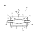
- FIG. 16 shows a perspective view of a tubular tissue preparation device in one embodiment.
- the schematics of the tubular tissue preparation device shown in the following FIGS. 2-5 represent cross-sectional views of the same plane P.
- FIG. 1 is a schematic cross-sectional view showing a tubular tissue preparation device in one embodiment.
- FIG. 1 is a schematic cross-sectional view showing a tubular tissue preparation device in one embodiment.
- FIG. 1 is a schematic cross-sectional view showing a tubular tissue preparation device in one embodiment.
- FIG. 1 is a schematic cross-sectional view showing a tubular tissue preparation device in one embodiment.
- FIG. 1 is a schematic cross-sectional view showing a tubular tissue preparation device in one embodiment.
- FIG. 1 is a schematic cross-sectional view showing a tubular tissue preparation device in one embodiment.
- FIG. 1 is a schematic cross-sectional view showing a tubular tissue preparation device in one embodiment.
- FIG. 1 is a schematic cross-sectional view showing a tubular tissue preparation device in one embodiment.
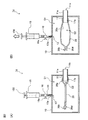
- the tubular tissue preparation device of the present invention shows the small intestine before and after decompression.
- A Small intestine before decompression
- B Small intestine after decompression.
- FIG. 1 shows the tubular tissue section image produced using the tubular tissue production device of this invention.
- Cell nuclei blue, Hoechst
- cardiac muscle troponin T green, cTnT
- Scale bar indicates 100 ⁇ m.
- FIG. 1 is a schematic cross-sectional view showing a tubular tissue preparation device in one embodiment.
- FIG. 1 shows the small intestine before and after decompression.
- A Small intestine before decompression
- B Small intestine after decompression.
- FIG. 1 shows the tubular tissue section image produced using the tubular tissue production device of this invention.
- Cell nuclei blue, Hoechst
- cardiac muscle troponin T green, cTnT
- tubular tissue refers to a structure obtained by attaching a sheet-like tissue to a tubular support.
- tubular support is a structure having a luminal structure, and particularly refers to a luminal structure derived from a living tissue.
- the tubular support for example, intestinal tract (small intestine, large intestine, etc.), digestive tract such as esophagus, stomach, etc., blood vessels, lymphatics, bile duct, ureter, bladder, urethra, trachea, uterus, fallopian tube etc. can be used.
- intestinal tract small intestine, large intestine, etc.
- digestive tract such as esophagus, stomach, etc.
- Conventionally, such a tubular support is often in a contracted state, and when attaching a sheet-like tissue to the inside, the sheet-like tissue falls off before reaching a desired site, making it difficult to attach Met.
- tubular support those collected in a state where arteries and veins are connected can be used so that the sheet-like tissue to be attached does not become necrotic.
- the tubular support can use the decellularized tubular support by a well-known method.
- the tubular support used in the present invention has at least one opening.
- openings first and second openings
- the opening of the tubular support is fixed to a support (a first support or a second support (described later)) provided in the tubular tissue production device of the present invention, and the external space of the chamber of the tubular tissue production device It is in communication with
- the opening of the tubular support used in the present invention may be artificially formed using a scalpel, scissors or the like.
- sheet-like tissue refers to one or more layers of sheet-shaped tissue containing any cells.
- the sheet-like tissue may be a sheet-like tissue recovered from a living tissue, may be obtained by mixing cells and a hydrogel, and may be cultured, or may be a cell sheet. .
- the origin of the cells used for producing the sheet-like tissue is not particularly limited.
- the cell type, the number of cells, the ratio of cells contained, and the like used for producing the sheet-like tissue may be appropriately selected or adjusted according to the use.
- the “cell sheet” refers to a cell group of one or more layers obtained by culturing on a cell culture substrate and peeling from the cell culture substrate.
- a method for obtaining a cell sheet for example, cells are cultured on a stimulus-responsive culture substrate coated with a polymer whose molecular structure is changed by a stimulus such as temperature, pH or light, and the stimulus such as temperature, pH or light is stimulated.
- a method of peeling cells in a sheet form from the stimulus-responsive culture substrate while maintaining the adhesion state between the cells by changing the surface of the stimulus-responsive culture substrate by changing the conditions of Cells are cultured, and physically exfoliated from the end of the cell culture substrate with tweezers or the like.
- a preferred embodiment is a method using a temperature-responsive culture substrate coated on the surface with a polymer whose hydration power changes in a temperature range of 0 to 80 ° C., as a stimulus-responsive culture substrate, for example,
- a cell sheet can be conveniently obtained by using UpCell (registered trademark) commercially available from Tokyo, Japan).
- the tubular support and the sheet-like tissue used in the present invention can be appropriately selected in combination according to the purpose, and is not limited.
- the cells contained in the sheet-like tissue can also be appropriately selected according to the purpose.
- FIG. 1 shows a perspective view of the appearance of a tubular tissue production device 1 according to an embodiment of the present invention (FIG. 1 is an appearance of a tubular tissue production device 1c described later).
- the views of the tubular tissue preparation device 1 of FIGS. 2-5 show a cross-sectional view of the same plane P of the tubular tissue preparation device 1 shown in FIG.
- FIG. 1-1 First Embodiment
- a chamber 10 for receiving a tubular support 20 A first support 11 for communicating the inside and the outside of the chamber 10 and for fixing the tubular support 20; Pressurizing and depressurizing means 15 for controlling the pressure of the internal space S1 of the chamber 10; Equipped with
- the first support 11 fixes the first opening 20a of the tubular support 20, communicates the lumen S2 of the tubular support 20 with the outside of the chamber, and the tubular support 20.
- the first support 11 is for separating the inner space S2 of the inner space S from the inner space S of the chamber 10.
- the chamber 10 includes a chamber body 10a and a chamber lid 10b.
- the space inside and outside the chamber 10 can be separated by combining the chamber body 10 a and the chamber lid 10 b.
- Seal members for example, an O-ring, packing, and the like
- the chamber body 10a and the chamber lid 10b are fixed by a chamber fixture 10d.
- the chamber fixture 10d can be fixed, for example, by a plurality of snap locks.
- a window 10 c is provided in a part of the chamber lid 10 b so that the inside of the chamber 10 can be viewed.
- a part of the chamber 10 is provided with a first support 11 for communicating the inside and the outside of the chamber 10 and for fixing the tubular support 20. Since the first support portion 11 communicates the inside and the outside of the chamber 10, the pressure in the tubular support 20 and the pressure in the external space of the chamber 10 can be equalized.
- the first support 11 is provided so as to protrude to the inside of the chamber 10, and thereby the first opening 20 a of the tubular support 20 can be fixed.
- the first support portion 11 has a cylindrical shape, and serves to communicate the space inside and outside the chamber 10.
- the shape of the first support portion 11 is not limited to a cylindrical shape, and may be a hollow prism (a triangular prism, a quadrangular prism, a hexagonal prism, etc.).
- the diameter of the first support portion 11 can be appropriately changed according to the diameter of the tubular support 20 used.
- the outer portion (the first outer end 11a of the first support) of the first support 11 of the chamber 10 may have a shape that protrudes as shown in FIG. 2, but does not protrude from the outer wall of the chamber 10 The shape may have only the first outer end opening 11b.
- the first support portion 11 and the first opening 20a of the tubular support 20 are fixed by the first seal member 17a.
- the first seal member 17a may be, for example, a suture or the like, and may be a pipe clip made of silicone rubber, natural rubber, resin, metal or the like. Further, the first seal member 17a may use a bioadhesive material such as fibrin gel, and any material having a function of bringing the first opening 20a and the first support 11 into close contact with each other is applicable. can do.
- a groove may be provided in a part of the first support portion 11 so that the first seal member 17a bites in and fixes the first opening 20a of the tubular support 20 more closely. it can.
- the chamber 10 is provided with pressurizing and depressurizing means 15 for controlling the pressure of the internal space S1 of the chamber 10.
- the pressurizing and depressurizing unit 15 is connected to the fluid inlet / outlet 13 communicating with the inside and the outside of the chamber 10 via the first flow path 14.
- the pressure reducing means 15 for example, a known means such as a syringe or a pump can be used.
- a syringe is preferable as the pressurizing and depressurizing means 15 because it is a simple mechanism and the delicate adjustment of the pressurizing and depressurizing is also possible.
- the pressure reducing means 15 may be provided in the chamber body 10 a of the chamber 10 or may be provided in the chamber lid 10 b.
- the first flow path 14 between the pressurizing and depressurizing means 15 and the fluid inlet / outlet 13 further includes a valve mechanism 16.
- the valve mechanism 16 can use, for example, a two-way stopcock or a clip. By rotating the cock 16 a of the valve mechanism 16, it is possible to keep the pressure in the internal space S ⁇ b> 1 of the chamber 10 pressurized or reduced by the pressurizing and depressurizing unit 15 constant.
- the tubular support 20 has an opening other than the first opening 20a (for example, the second opening 20b in FIG. 2A). It is necessary to close by the closing means 20d etc. Thereby, the lumen S2 of the tubular support 20 and the internal space S2 of the chamber 10 can be isolated. In this state, when the pressure in the internal space S2 of the chamber 10 is reduced by the pressurizing / depressurizing means 15, as shown in FIG. Thus, conventionally, when attaching a sheet-like tissue to the inside of a tubular support, it is difficult to attach without damaging the sheet-like tissue because the tubular support is shrunk and collapsed. It becomes possible to apply a sheet-like tissue simply and stably.
- tubular tissue producing device 1b is a part of the chamber 10 in addition to the respective members of the tubular tissue producing device 1a.
- a second support 12 is provided for communicating the inside and the outside of the chamber and for fixing the tubular support (FIG. 3).
- the second support 12 fixes the second opening 20b of the tubular support 20, communicates the lumen S2 of the tubular support 20 with the outside of the chamber 10, and communicates with the lumen S2 of the tubular support 20. It isolates from the internal space S1 of the chamber. With the second support 12 communicating the inside and the outside of the chamber 10, the pressure in the tubular support 20 and the pressure in the external space of the chamber 10 can be made the same.
- the second support 12 is provided so as to protrude to the inside of the chamber 10, whereby the second opening 20b of the tubular support 20 can be fixed.
- the second support 12 has a cylindrical shape, and serves to communicate the space inside and outside the chamber 10.
- the shape of the second support 12 is not limited to a cylindrical shape, and may be a hollow prism (a triangular prism, a quadrangular prism, a hexagonal prism, or the like).
- the diameter of the second support 12 can be appropriately changed according to the diameter of the tubular support 20 used.
- the outer portion of the second support 12 of the chamber 10 (the second outer end 12 a of the second support) may be shaped to protrude as shown in FIG. 3, but does not protrude from the outer wall of the chamber 10. , And the second outer end opening 12b may be formed.
- the second support 12 and the second opening 20b of the tubular support 20 are fixed by the second seal member 17b.
- the second seal member 17b may be, for example, a suture thread, or a pipe clip made of silicone rubber, natural rubber, resin, metal or the like. Further, the second seal member 17b may use a bioadhesive material such as fibrin gel, and it is applicable if it has a function of bringing the second opening 20b and the second support 12 into close contact with each other. can do.
- a groove may be provided in a part of the second support portion 12 so that the second seal member 17 b bites in, and the second opening 20 b of the tubular support 20 can be more closely fixed and fixed. it can.
- the second support 12 may have the same diameter as the first support 11 or may have a different diameter.
- the first support 11 and the second support 12 are disposed to face both ends of the chamber 10 as shown in FIG. Thereby, the tubular support 20 can be expanded uniformly (FIG. 3-1 (B)).
- the elastic member 15a is changed to the original shape or a further convex shape by pulling the grip portion 150a.
- the pressure of the internal space S1 decreases.
- a pressure difference occurs between the inside and the outside of the tubular support 20, and the tubular support 20 expands.
- the tubular tissue producing device 1 d includes the tubular tissue producing device 1 a, the tubular tissue producing device 1 b or the tubular tissue producing device 1 c in addition to the respective members of the chamber 10. Partly: An arterial connection 18a in communication with the inside and the outside of the chamber 10 and connected to the culture medium supply channel 19a; It further communicates with the inside and outside of the chamber 10, and further includes a vein connection 18b connected to the culture medium discharge channel 19b.
- the tubular support 20 is a tubular support 20 having an artery 21 and a vein 22
- the artery 21 and the vein 22 can be connected to the arterial connection 18a and the venous connection 18b, respectively.
- the vein connection portion 18b communicates with the culture medium discharge channel 19b, and is further connected to a culture medium discharge layer (not shown).
- a culture medium discharge layer not shown.
- tubular Tissue Production Kit In one embodiment, the present invention provides a tubular tissue production kit comprising the above-described tubular tissue production device 1 (1a, 1b, 1c, 1d) and a sheet-like tissue transfer device 30.
- the sheet-like tissue transfer device 30 As the sheet-like tissue transfer device 30, a device having a function of mounting the sheet-like tissue ST and adhering the sheet-like tissue ST to an arbitrary part of the inner wall 20c of the tubular support 20 can be used.
- the devices described in Japanese Patent Application Laid-Open No. -79783 and WO 2017/043600 can be used.
- the sheet-like tissue transfer device 30 includes the fluid supply pipe 32, a cylindrical portion 33 provided at its tip, and the outer peripheral surface of the cylindrical portion 33. And expansion and contraction means 31 provided so as to be able to expand and contract.
- the sheet-like tissue ST is wound around the expansion and contraction means 31.
- the sheet-like tissue transfer device 30 carrying the sheet-like tissue ST is inserted from the first outer end opening 11 b of the first support portion 11 by being expanded by the above-described tubular tissue preparation device 1 (1a, 1b, 1c, 1d) . Thereafter, the fluid is fed to the expansion and contraction means 31 through the fluid supply pipe 32, and the expansion and contraction means 31 is expanded.
- the sheet-like tissue ST can be brought into close contact with the inner wall 20 c of the tubular support 20, and the sheet-like tissue ST can be attached to the inner wall 20 c of the tubular support 20.
- the sheet-like tissue transfer device 30 can adopt at least a sheet-like tissue and any shape that can pass through the first outer end opening 11 b of the first support portion 11. It is preferable to have the expansion and contraction means 31 in that the sheet-like tissue ST can be simply and uniformly attached to the inner wall 20c of the tubular support 20.
- the expansion and contraction means 31 for example, a balloon can be used.
- the present invention provides a method for producing a tubular tissue using the above-mentioned tubular tissue production device 1 (1a, 1b, 1c, 1d) and a sheet-like tissue transfer device 30.
- the above-mentioned thing is applied to the description of the tubular tissue preparation device 1 (1a, 1b, 1c, 1d) and the sheet-like tissue transfer device 30.
- the method of producing a tubular tissue comprises A chamber 10 for receiving a tubular support 20; A first support 11 for communicating the inside and the outside of the chamber 10 and for fixing the tubular support 20; Pressurizing and depressurizing means 15 for controlling the pressure of the internal space S1 of the chamber 10;
- the tubular tissue preparation device 1a comprising (1) connecting the lumen S2 of the tubular support 20 with the outside of the chamber 10 by fixing the first opening 20a of the tubular support 20 to the first support 11; (2) isolating the lumen S2 of the tubular support 20 and the internal space S1 of the chamber 10; (3) decompressing the internal space S1 of the chamber 10 by the pressurizing and depressurizing means 15 and expanding the tubular support 20;
- the sheet-like tissue transfer device 30 carrying the sheet-like tissue ST is inserted from the first outer end opening 11b of the first support portion 11, and the sheet-like tissue ST is inserted into the inner wall 20c of the tubular support 20. Sticking process, Contains.
- the tubular tissue preparation device 1a if the tubular support 20 has an opening other than the first opening 20a (for example, the second opening 20b in FIG. 2A), the opening is closed. It needs to be closed by means 20d or the like. Thereby, the lumen S2 of the tubular support 20 and the internal space S2 of the chamber 10 can be separated (step (2)).
- the method of producing a tubular tissue comprises The inside and the outside of the chamber 10 may be communicated, and the tubular tissue production device 1 b further including a second support 12 for fixing the tubular support 20 may be used.
- the step (2) includes the step of connecting the lumen S2 of the tubular support 20 with the outside of the chamber 10 by fixing the second opening 20b of the tubular support 20 to the second support 12. By carrying out, the lumen S2 of the tubular support 20 and the internal space S2 of the chamber 10 can be isolated.
- a step of pressurizing the internal space S1 of the chamber 10 by the pressurizing and depressurizing means 15 and contracting the tubular support 20 can be performed (FIG. 3-3).
- the internal space S1 of the chamber 10 is pressurized by the pressurizing and depressurizing means 15, and the tubular support 20 is contracted to form the inner wall 20c of the tubular support 20 and the sheet-like tissue ST. Can be more closely attached. Thereby, the sheet-like tissue ST to be attached can be promoted to be engrafted to the tubular support 20.
- the degree of depressurization and / or pressurization by the pressurizing / depressing means (the pressurizing / depressing means 15, the elastic member 15a) of the tubular tissue production device 1 (1a, 1b, 1c, 1d) of the present invention is the property of the tubular support 20 used. And the degree of expansion and / or contraction of the tubular support 20 can be appropriately adjusted while observing the degree of expansion and / or contraction.
- tubular support (small intestine) used in the examples was collected as follows. Under anesthesia with a 3% isoflurane concentration, rats underwent a midline incision in the abdomen to expose the ileum. The ileum and ileal artery and vein were separated using scissors, and the ileum was isolated by cutting 5 cm from the ileocecal side to the ileum side.
- Cardiomyocytes were prepared according to the method of Matsuura et al. (Katsuura M. et al., Creation of human cardiac cell sheets using pluripotent stem cells, Biochemical and Biophysical Research Communications, 425, 2012.). Specifically, human iPS cells were induced to differentiate into cardiomyocytes and recovered in a rotary bioreactor. During differentiation induction, StemPro 34 medium mixed with ascorbic acid (Sigma-Aldrich) at 50 ⁇ g / ml, L-glutamine at 2 mM, and 1-thioglycerol (Sigma-Aldrich) at a concentration of 400 ⁇ M is used as a basal medium. The following growth factors were added and used.
- Day 0 to 1 0.5 ng / mL BMP4 (R & D systems, Minnea poils, MN); (2) Days 1-4: 10 ng / ml BMP4, 5 ng / ml bFGF, 3 ng / ml activin A (R & D systems); (3) Days 4 to 6: 4 ⁇ M IWR-1 (Wako); (4) Days 6 to 16: 5 ng / ml VEGF, 10 ng / ml bFGF.
- the medium was changed to Days 1, 4, 6, 8, 10, 12 and 14.
- Cells harvested from the bioreactor on Day 16 were seeded at a concentration of 1.0 ⁇ 10 7 cells / 10 cm dish.
- the medium used at this time was DMEM containing 10% FBS and 1% penicillin streptomycin.
- puromycin was mixed to a concentration of 100 ng / ml, and cultured in a 37 ° C. incubator under 5% CO 2 and saturated steam. The medium was changed on Days 1, 3, 5, 7, 10 and 12, and cells were recovered using Trypsin-EDTA solution on Day 14.
- the collected cells and human skin fibroblasts are seeded at a concentration of 1,000,000 cells / culture dish on a temperature-responsive 35 mm culture dish (UpCell (R), Cellseed Inc.), 10% FBS, 1%
- the cells were cultured in DMEM containing penicillin streptomycin for 1 week in a 37 ° C. incubator under saturated steam at 5% CO 2 . Thereafter, the cells were collected as a cell sheet by incubating at 20 ° C.
- HE staining ⁇ Hematoxylin and eosin (HE) staining, immunostaining>
- the collected tissue was fixed in paraffin, sliced at a thickness of 5 ⁇ m, and then the morphology of the laminated tissue was evaluated by performing HE staining and immunostaining.
- the openings at both ends of the tubular small intestine were connected to a silicone tube (corresponding to the first support 11 and the second support 12 in FIG. 6) communicating with the outside of the chamber. This ensures that the lumen of the small intestine is always maintained at atmospheric pressure.
- a silicone tube At the lid of the closed chamber, there was a location open to the atmosphere via a silicone tube, from which the air inside the chamber was drawn. This causes the pressure in the chamber to decrease, creating a pressure differential with the small intestinal lumen which is maintained at atmospheric pressure.
- the pressure in the chamber was reduced until the small intestine was fully expanded due to the pressure difference generated at this time. With the small intestine fully expanded, the open area was shut off and the chamber was sealed to maintain the internal pressure. As a result, the small intestine can be maintained in the expanded state, and the sheet-like tissue transfer device is inserted into the expanded small intestine, and the cell sheet is attached to the inner wall of the small intestine (FIG. 6).
- Example 2 Decompression and lamination results of the myocardial cell sheet on the inner wall of the small intestine
- the tubular tissue preparation device used in the present invention when the pressure was reduced and the small intestine was expanded, the small intestine was expanded due to the pressure difference (FIG. 6).
- the sheet-like tissue transfer device was inserted into the expanded small intestine and the cardiomyocyte sheet was laminated on the inner wall, the cell sheet attached to the inner wall of the small intestine could be confirmed (FIG. 7).
- the attached cardiomyocyte sheet was laminated in accordance with the shape of the small intestine (FIG. 8). It is considered that this is because the myocardial cell sheet is crimped to the small intestine by lamination using the tubular tissue preparation device of the present invention.
- 1, 1a, 1b, 1c, 1d tubular tissue preparation device, 10: chamber, 10a: chamber body, 10b: chamber lid, 10c: window, 10d: chamber fixture, 11: first support, 11a: First outer end, 11b: first outer end opening, 12: second support, 12a: second outer end, 12b: second outer end opening, 13: fluid outlet, 13a: connector, 14: first 1 flow path, 15: compression / decompression means, 150: piston, 15a, 15a ': elastic member, 150a: grip portion, 15b: check valve, 16: valve mechanism, 16a: cock, 17a: first seal member, 17b : 2nd sealing member, 17c: 3rd sealing member, 17d: 4th sealing member, 18a: arterial connection, 18b: vein connection, 19a: culture medium supply flow channel, 19b: culture medium discharge flow channel, 20: tubular support Body, 20a: 1st Mouth 20b: second opening 20c: inner wall 20d: opening closing means 21: artery 22: veins 30:
Landscapes
- Chemical & Material Sciences (AREA)
- Health & Medical Sciences (AREA)
- Engineering & Computer Science (AREA)
- Life Sciences & Earth Sciences (AREA)
- Bioinformatics & Cheminformatics (AREA)
- Zoology (AREA)
- Wood Science & Technology (AREA)
- Organic Chemistry (AREA)
- Biomedical Technology (AREA)
- Materials Engineering (AREA)
- Genetics & Genomics (AREA)
- General Health & Medical Sciences (AREA)
- Biotechnology (AREA)
- Manufacturing & Machinery (AREA)
- Sustainable Development (AREA)
- Biochemistry (AREA)
- General Engineering & Computer Science (AREA)
- Microbiology (AREA)
- Medicinal Chemistry (AREA)
- Analytical Chemistry (AREA)
- Molecular Biology (AREA)
- Epidemiology (AREA)
- Veterinary Medicine (AREA)
- Oral & Maxillofacial Surgery (AREA)
- Transplantation (AREA)
- Dermatology (AREA)
- Animal Behavior & Ethology (AREA)
- Public Health (AREA)
- Mechanical Engineering (AREA)
- Physics & Mathematics (AREA)
- Optics & Photonics (AREA)
- Immunology (AREA)
- Cell Biology (AREA)
- Botany (AREA)
- Chemical Kinetics & Catalysis (AREA)
- Materials For Medical Uses (AREA)
- Apparatus Associated With Microorganisms And Enzymes (AREA)
- Micro-Organisms Or Cultivation Processes Thereof (AREA)
Abstract
La présente invention concerne un dispositif de préparation de tissu tubulaire comprenant : une chambre destinée à recevoir un corps de support tubulaire ; une première partie de support pour faire communiquer l'intérieur et l'extérieur de la chambre et fixer le corps de support tubulaire ; et un moyen de mise sous pression/dépressurisation pour commander la pression dans un espace interne de la chambre, la première partie de support étant destinée à fixer une première section d'ouverture du corps de support tubulaire, à faire communiquer une lumière du corps de support tubulaire et l'extérieur de la chambre, et à séparer la lumière du corps de support tubulaire et l'espace interne de la chambre. La présente invention concerne également un kit de préparation de tissu tubulaire qui comprend ledit dispositif et un dispositif de transport d'un tissu en forme de feuille. De plus, la présente invention concerne un procédé de préparation de tissu tubulaire utilisant ledit dispositif.
Priority Applications (3)
| Application Number | Priority Date | Filing Date | Title |
|---|---|---|---|
| US16/771,203 US11458688B2 (en) | 2017-12-11 | 2018-10-19 | Tubular tissue preparation device, tubular tissue preparation kit, and tubular tissue preparation method |
| JP2019558944A JP7308525B2 (ja) | 2017-12-11 | 2018-10-19 | 管状組織作製デバイス、管状組織作製キット及び管状組織の作製方法 |
| EP18887289.9A EP3725869A4 (fr) | 2017-12-11 | 2018-10-19 | Dispositif de préparation de tissu tubulaire, kit de préparation de tissu tubulaire et procédé de préparation de tissu tubulaire |
Applications Claiming Priority (2)
| Application Number | Priority Date | Filing Date | Title |
|---|---|---|---|
| JP2017236746 | 2017-12-11 | ||
| JP2017-236746 | 2017-12-11 |
Publications (1)
| Publication Number | Publication Date |
|---|---|
| WO2019116726A1 true WO2019116726A1 (fr) | 2019-06-20 |
Family
ID=66819159
Family Applications (1)
| Application Number | Title | Priority Date | Filing Date |
|---|---|---|---|
| PCT/JP2018/039072 Ceased WO2019116726A1 (fr) | 2017-12-11 | 2018-10-19 | Dispositif de préparation de tissu tubulaire, kit de préparation de tissu tubulaire et procédé de préparation de tissu tubulaire |
Country Status (4)
| Country | Link |
|---|---|
| US (1) | US11458688B2 (fr) |
| EP (1) | EP3725869A4 (fr) |
| JP (1) | JP7308525B2 (fr) |
| WO (1) | WO2019116726A1 (fr) |
Families Citing this family (1)
| Publication number | Priority date | Publication date | Assignee | Title |
|---|---|---|---|---|
| US11420360B2 (en) * | 2020-09-11 | 2022-08-23 | Paula Noël Macfie | Latching mechanism for suppository mold |
Citations (7)
| Publication number | Priority date | Publication date | Assignee | Title |
|---|---|---|---|---|
| JPH02211865A (ja) | 1989-02-10 | 1990-08-23 | Kao Corp | 細胞培養支持体材料 |
| JP2005502351A (ja) * | 2001-09-11 | 2005-01-27 | アイシス イノヴェイション リミテッド | 生きている有機的組織を成長させるための方法および構造物 |
| JP2008079783A (ja) | 2006-09-27 | 2008-04-10 | Pentax Corp | 生体管路内処置デバイス |
| JP2008148887A (ja) * | 2006-12-18 | 2008-07-03 | Pentax Corp | 生体管路内処置デバイス |
| JP2010539938A (ja) * | 2007-09-24 | 2010-12-24 | ノーティス,インク. | 灌流可能な微小血管システムを作製するための方法 |
| WO2012036224A1 (fr) | 2010-09-14 | 2012-03-22 | 学校法人 東京女子医科大学 | Procédé de production de feuillets de cellules superposées, feuillets de cellules superposées dotés d'un réseau vasculaire obtenu par ce procédé, et procédé d'utilisation associé |
| WO2017043600A1 (fr) | 2015-09-09 | 2017-03-16 | 学校法人東京女子医科大学 | Dispositif d'administration de substance thérapeutique et kit d'administration de substance thérapeutique |
Family Cites Families (7)
| Publication number | Priority date | Publication date | Assignee | Title |
|---|---|---|---|---|
| US4839280A (en) * | 1987-05-04 | 1989-06-13 | Banes Albert J | Apparatus for applying stress to cell cultures |
| US5284766A (en) | 1989-02-10 | 1994-02-08 | Kao Corporation | Bed material for cell culture |
| US6107081A (en) * | 1999-02-05 | 2000-08-22 | The United States Of America As Represented By The Administrator Of The National Aeronautics And Space Administration | Uni-directional cell stretching device |
| WO2003089566A1 (fr) * | 2002-04-22 | 2003-10-30 | Tufts University | Bioreacteur a contraintes multidimensionnelles |
| DE102006039823A1 (de) * | 2005-02-25 | 2008-03-20 | Strecker, Ernst Peter, Prof. Dr. med. | Katheter-Stent-Vorrichtung |
| CA2615208A1 (fr) * | 2005-07-12 | 2007-01-18 | Tissue Genesis, Inc. | Appareil et methodes de preparation de greffes de tissus |
| US20140255967A1 (en) | 2013-03-06 | 2014-09-11 | Michael Dancu | System and method for coating or impregnating a structure with cells that exhibit an in vivo physiologic function |
-
2018
- 2018-10-19 WO PCT/JP2018/039072 patent/WO2019116726A1/fr not_active Ceased
- 2018-10-19 US US16/771,203 patent/US11458688B2/en active Active
- 2018-10-19 EP EP18887289.9A patent/EP3725869A4/fr not_active Withdrawn
- 2018-10-19 JP JP2019558944A patent/JP7308525B2/ja active Active
Patent Citations (7)
| Publication number | Priority date | Publication date | Assignee | Title |
|---|---|---|---|---|
| JPH02211865A (ja) | 1989-02-10 | 1990-08-23 | Kao Corp | 細胞培養支持体材料 |
| JP2005502351A (ja) * | 2001-09-11 | 2005-01-27 | アイシス イノヴェイション リミテッド | 生きている有機的組織を成長させるための方法および構造物 |
| JP2008079783A (ja) | 2006-09-27 | 2008-04-10 | Pentax Corp | 生体管路内処置デバイス |
| JP2008148887A (ja) * | 2006-12-18 | 2008-07-03 | Pentax Corp | 生体管路内処置デバイス |
| JP2010539938A (ja) * | 2007-09-24 | 2010-12-24 | ノーティス,インク. | 灌流可能な微小血管システムを作製するための方法 |
| WO2012036224A1 (fr) | 2010-09-14 | 2012-03-22 | 学校法人 東京女子医科大学 | Procédé de production de feuillets de cellules superposées, feuillets de cellules superposées dotés d'un réseau vasculaire obtenu par ce procédé, et procédé d'utilisation associé |
| WO2017043600A1 (fr) | 2015-09-09 | 2017-03-16 | 学校法人東京女子医科大学 | Dispositif d'administration de substance thérapeutique et kit d'administration de substance thérapeutique |
Non-Patent Citations (3)
| Title |
|---|
| KATSUURA M. ET AL.: "Creation of human cardiac cell sheets using pluripotent stem cells", BIOCHEMICAL AND BIOPHYSICAL RESEARCH COMMUNICATIONS, vol. 425, 2012, XP055482020, DOI: 10.1016/j.bbrc.2012.07.089 |
| See also references of EP3725869A4 |
| SEKINE H ET AL.: "Pulsatile myocardial tubes fabricated with cell sheet engineering", CIRCULATION, vol. 114, no. 1, 4 July 2006 (2006-07-04), pages 187 - 93 |
Also Published As
| Publication number | Publication date |
|---|---|
| JP7308525B2 (ja) | 2023-07-14 |
| EP3725869A1 (fr) | 2020-10-21 |
| EP3725869A4 (fr) | 2021-08-04 |
| US20200368972A1 (en) | 2020-11-26 |
| JPWO2019116726A1 (ja) | 2020-12-03 |
| US11458688B2 (en) | 2022-10-04 |
Similar Documents
| Publication | Publication Date | Title |
|---|---|---|
| JP2022107023A (ja) | 臓器および組織を脱細胞化および再細胞化する方法 | |
| CN101272815B (zh) | 器官和组织的脱细胞化和再细胞化 | |
| JP7465294B2 (ja) | 組織を培養する装置及び方法 | |
| EP2842581B1 (fr) | Structure en forme de poche avec activité de paracrine et son procédé de préparation | |
| EP2617811B1 (fr) | Procédé de fabrication de feuillet cellulaire multicouche, feuillet cellulaire multicouche ayant un réseau vasculaire obtenu par le procédé, procédé d'utilisation de celui-ci | |
| US7846728B2 (en) | Tissue engineering in vivo with vascularized scaffolds | |
| JP2001506871A (ja) | 人工腎臓および腎臓疾患治療へのその利用 | |
| JP7308525B2 (ja) | 管状組織作製デバイス、管状組織作製キット及び管状組織の作製方法 | |
| US20090123993A1 (en) | Bioreactor for development of blood vessels | |
| JP2005278711A (ja) | ハニカムフィルムを用いた機能的人工組織の生産 | |
| Sekine et al. | Tubular cardiac tissue bioengineered from multi-layered cell sheets for use in the treatment of heart failure | |
| JP5252538B2 (ja) | 弾性線維組織を有する培養血管の製造方法及び弾性線維組織を有する培養血管 | |
| WO2023235737A1 (fr) | Dispositif à agent de remplissage de tunnel et méthodes d'utilisation | |
| JP2021023826A (ja) | 創傷被覆用シート、及び創傷被覆方法 | |
| TWI507181B (zh) | 腹腔內力學刺激製造高強度組織工程材料的系統 | |
| Poot et al. | Y. Song1, J.-L. Hillebrands2, JH Zandvoort3, CJAM Zeebregts4, RH Geelkerken5 | |
| HK1170662A (en) | Decellularization and recellularization of organs and tissues | |
| CN103251979A (zh) | 一种人工尿液流出道及其制备方法 | |
| CN106834222A (zh) | 一种培育带血管蒂骨瓣的方法 |
Legal Events
| Date | Code | Title | Description |
|---|---|---|---|
| 121 | Ep: the epo has been informed by wipo that ep was designated in this application |
Ref document number: 18887289 Country of ref document: EP Kind code of ref document: A1 |
|
| ENP | Entry into the national phase |
Ref document number: 2019558944 Country of ref document: JP Kind code of ref document: A |
|
| NENP | Non-entry into the national phase |
Ref country code: DE |
|
| ENP | Entry into the national phase |
Ref document number: 2018887289 Country of ref document: EP Effective date: 20200713 |