WO2019116793A1 - 車載システム、及び、検出器ハブ - Google Patents
車載システム、及び、検出器ハブ Download PDFInfo
- Publication number
- WO2019116793A1 WO2019116793A1 PCT/JP2018/041513 JP2018041513W WO2019116793A1 WO 2019116793 A1 WO2019116793 A1 WO 2019116793A1 JP 2018041513 W JP2018041513 W JP 2018041513W WO 2019116793 A1 WO2019116793 A1 WO 2019116793A1
- Authority
- WO
- WIPO (PCT)
- Prior art keywords
- vehicle
- detector
- detectors
- control device
- network
- Prior art date
- Legal status (The legal status is an assumption and is not a legal conclusion. Google has not performed a legal analysis and makes no representation as to the accuracy of the status listed.)
- Ceased
Links
Images



Classifications
-
- B—PERFORMING OPERATIONS; TRANSPORTING
- B60—VEHICLES IN GENERAL
- B60R—VEHICLES, VEHICLE FITTINGS, OR VEHICLE PARTS, NOT OTHERWISE PROVIDED FOR
- B60R16/00—Electric or fluid circuits specially adapted for vehicles and not otherwise provided for; Arrangement of elements of electric or fluid circuits specially adapted for vehicles and not otherwise provided for
- B60R16/02—Electric or fluid circuits specially adapted for vehicles and not otherwise provided for; Arrangement of elements of electric or fluid circuits specially adapted for vehicles and not otherwise provided for electric constitutive elements
- B60R16/023—Electric or fluid circuits specially adapted for vehicles and not otherwise provided for; Arrangement of elements of electric or fluid circuits specially adapted for vehicles and not otherwise provided for electric constitutive elements for transmission of signals between vehicle parts or subsystems
- B60R16/0238—Electrical distribution centers
-
- H—ELECTRICITY
- H04—ELECTRIC COMMUNICATION TECHNIQUE
- H04L—TRANSMISSION OF DIGITAL INFORMATION, e.g. TELEGRAPHIC COMMUNICATION
- H04L12/00—Data switching networks
- H04L12/28—Data switching networks characterised by path configuration, e.g. LAN [Local Area Networks] or WAN [Wide Area Networks]
- H04L12/40—Bus networks
- H04L12/40169—Flexible bus arrangements
- H04L12/40176—Flexible bus arrangements involving redundancy
- H04L12/40189—Flexible bus arrangements involving redundancy by using a plurality of bus systems
-
- G—PHYSICS
- G01—MEASURING; TESTING
- G01S—RADIO DIRECTION-FINDING; RADIO NAVIGATION; DETERMINING DISTANCE OR VELOCITY BY USE OF RADIO WAVES; LOCATING OR PRESENCE-DETECTING BY USE OF THE REFLECTION OR RERADIATION OF RADIO WAVES; ANALOGOUS ARRANGEMENTS USING OTHER WAVES
- G01S13/00—Systems using the reflection or reradiation of radio waves, e.g. radar systems; Analogous systems using reflection or reradiation of waves whose nature or wavelength is irrelevant or unspecified
- G01S13/86—Combinations of radar systems with non-radar systems, e.g. sonar, direction finder
-
- G—PHYSICS
- G05—CONTROLLING; REGULATING
- G05D—SYSTEMS FOR CONTROLLING OR REGULATING NON-ELECTRIC VARIABLES
- G05D1/00—Control of position, course, altitude or attitude of land, water, air or space vehicles, e.g. using automatic pilots
- G05D1/0088—Control of position, course, altitude or attitude of land, water, air or space vehicles, e.g. using automatic pilots characterized by the autonomous decision making process, e.g. artificial intelligence, predefined behaviours
-
- H—ELECTRICITY
- H04—ELECTRIC COMMUNICATION TECHNIQUE
- H04L—TRANSMISSION OF DIGITAL INFORMATION, e.g. TELEGRAPHIC COMMUNICATION
- H04L12/00—Data switching networks
- H04L12/28—Data switching networks characterised by path configuration, e.g. LAN [Local Area Networks] or WAN [Wide Area Networks]
- H04L12/40—Bus networks
-
- H—ELECTRICITY
- H04—ELECTRIC COMMUNICATION TECHNIQUE
- H04L—TRANSMISSION OF DIGITAL INFORMATION, e.g. TELEGRAPHIC COMMUNICATION
- H04L12/00—Data switching networks
- H04L12/66—Arrangements for connecting between networks having differing types of switching systems, e.g. gateways
-
- H—ELECTRICITY
- H05—ELECTRIC TECHNIQUES NOT OTHERWISE PROVIDED FOR
- H05K—PRINTED CIRCUITS; CASINGS OR CONSTRUCTIONAL DETAILS OF ELECTRIC APPARATUS; MANUFACTURE OF ASSEMBLAGES OF ELECTRICAL COMPONENTS
- H05K7/00—Constructional details common to different types of electric apparatus
- H05K7/02—Arrangements of circuit components or wiring on supporting structure
- H05K7/026—Multiple connections subassemblies
-
- G—PHYSICS
- G01—MEASURING; TESTING
- G01S—RADIO DIRECTION-FINDING; RADIO NAVIGATION; DETERMINING DISTANCE OR VELOCITY BY USE OF RADIO WAVES; LOCATING OR PRESENCE-DETECTING BY USE OF THE REFLECTION OR RERADIATION OF RADIO WAVES; ANALOGOUS ARRANGEMENTS USING OTHER WAVES
- G01S15/00—Systems using the reflection or reradiation of acoustic waves, e.g. sonar systems
- G01S15/87—Combinations of sonar systems
-
- G—PHYSICS
- G01—MEASURING; TESTING
- G01S—RADIO DIRECTION-FINDING; RADIO NAVIGATION; DETERMINING DISTANCE OR VELOCITY BY USE OF RADIO WAVES; LOCATING OR PRESENCE-DETECTING BY USE OF THE REFLECTION OR RERADIATION OF RADIO WAVES; ANALOGOUS ARRANGEMENTS USING OTHER WAVES
- G01S15/00—Systems using the reflection or reradiation of acoustic waves, e.g. sonar systems
- G01S15/88—Sonar systems specially adapted for specific applications
- G01S15/93—Sonar systems specially adapted for specific applications for anti-collision purposes
- G01S15/931—Sonar systems specially adapted for specific applications for anti-collision purposes of land vehicles
-
- H—ELECTRICITY
- H01—ELECTRIC ELEMENTS
- H01R—ELECTRICALLY-CONDUCTIVE CONNECTIONS; STRUCTURAL ASSOCIATIONS OF A PLURALITY OF MUTUALLY-INSULATED ELECTRICAL CONNECTING ELEMENTS; COUPLING DEVICES; CURRENT COLLECTORS
- H01R2201/00—Connectors or connections adapted for particular applications
- H01R2201/26—Connectors or connections adapted for particular applications for vehicles
-
- H—ELECTRICITY
- H04—ELECTRIC COMMUNICATION TECHNIQUE
- H04L—TRANSMISSION OF DIGITAL INFORMATION, e.g. TELEGRAPHIC COMMUNICATION
- H04L12/00—Data switching networks
- H04L12/28—Data switching networks characterised by path configuration, e.g. LAN [Local Area Networks] or WAN [Wide Area Networks]
- H04L12/40—Bus networks
- H04L2012/40267—Bus for use in transportation systems
- H04L2012/40273—Bus for use in transportation systems the transportation system being a vehicle
Definitions
- the present invention relates to an in-vehicle system and a detector hub.
- Patent Document 1 discloses an in-vehicle information system that configures a network that can mutually communicate with each other through a plurality of communication interfaces between a plurality of devices mounted in the vehicle. It is done.
- the present invention has been made in view of the above-described circumstances, and an object thereof is to provide an on-vehicle system and a detector hub capable of securing appropriate communication.
- an in-vehicle system includes: a plurality of detectors provided in a vehicle; and an in-vehicle device mounted on the vehicle based on detection information indicating detection results by the plurality of detectors.
- a controller for controlling a plurality of detectors, and the plurality of detectors and the controller so as to be mutually communicable, and a detector hub for collecting the detection information by the plurality of detectors and transmitting the information to the controller And.
- a first network for communicably connecting the in-vehicle device and the control device, a network independent of the first network, and the plurality of detectors and the detector hub
- a second network communicably connecting to the control device may be provided.
- the plurality of detector hubs are provided, and the detection information by the plurality of mutually different detectors is collected, and the second network mutually communicates the plurality of detector hubs A ring network connected as much as possible can be configured.
- the detector hub may include an abnormality determination unit that determines an abnormality of the detector.
- the on-vehicle system may further include a curl cord connecting the detector hub and the detector.
- a detector hub includes a detector connection portion communicably connected to a plurality of detectors provided in a vehicle, and detection results obtained by the plurality of detectors.
- a control device connecting unit communicably connected to a control device for controlling the on-vehicle device mounted on the vehicle based on the detection information representing the detection information collected by the plurality of detectors and the control device And a communication processing unit for transmitting data.
- the on-vehicle system and the detector hub according to the present invention are configured such that a plurality of detectors and a control device can communicate with each other via the detector hub.
- the detector hub aggregates detection information from the plurality of detectors and transmits the information to the control device.
- the in-vehicle system and the detector hub have an effect that proper communication can be ensured.
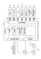
- FIG. 1 is a block diagram showing a schematic configuration of a vehicle-mounted system according to the embodiment.
- FIG. 2 is a block diagram for explaining the arrangement of a plurality of detector hubs provided in the in-vehicle system according to the embodiment.
- FIG. 3 is a block diagram showing a schematic configuration of a detector hub provided in the in-vehicle system according to the embodiment.
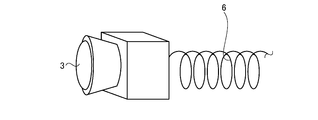
- FIG. 4 is a schematic perspective view showing an example of a curled cord provided in the in-vehicle system according to the embodiment.
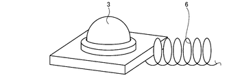
- FIG. 5 is a schematic perspective view showing an example of a curled cord provided in the in-vehicle system according to the embodiment.
- FIG. 6 is a schematic perspective view showing an example of a curled cord provided in the in-vehicle system according to the embodiment.
- the in-vehicle system 1 of the present embodiment shown in FIG. 1 is an in-vehicle network system which is mounted on a vehicle V and in which the plurality of detectors 3 are integrated by the detector hub 5 in the vehicle V.
- the on-vehicle system 1 is realized by mounting the components shown in FIG.
- the configuration of the in-vehicle system 1 will be described in detail with reference to the drawings.
- connection method between each component for supplying and receiving the power supply, control signal, various information and the like is a wiring material such as an electric wire or an optical fiber unless otherwise noted.
- the connection may be wired (for example, including optical communication via an optical fiber) via wireless communication, wireless communication, wireless connection such as non-contact power feeding, or the like.
- the vehicle V to which the in-vehicle system 1 is applied is any of an electric vehicle (EV), a hybrid vehicle (HEV), a plug-in hybrid vehicle (PHEV), a gasoline vehicle, a diesel vehicle, etc. using a motor or engine as a drive source. It may be a vehicle.
- FIG. 1, FIG. 2, and FIG. 3 which are explained below are illustrated in a state in which all or a part of a plurality of provided detector hubs 5 is abbreviated as “HUB”.
- the in-vehicle system 1 includes a plurality of in-vehicle devices 2, a plurality of detectors 3, a control device 4, a detector hub 5, and a curl cord 6. Prepare. Further, the in-vehicle system 1 includes a first network N1 and a second network N2 as an in-vehicle LAN (Local Area Network) that communicably connects them.
- LAN Local Area Network
- the in-vehicle device 2 is a device mounted on the vehicle V to realize various functions.
- a plurality of in-vehicle devices 2 are provided in the vehicle V.
- the plurality of on-vehicle devices 2 may be installed on the vehicle V at the time of manufacturing the vehicle V, for example, or may be a so-called after-sales product installed on the vehicle V retrofitted after the vehicle V is manufactured.
- the plurality of in-vehicle devices 2 may include, for example, traveling system actuators, power supply devices, vehicle environment devices, multimedia (Multi Media) devices, and the like.
- the travel system actuator includes, for example, a power train for travel (engine, motor generator, transmission) which is a drive device for traveling the vehicle V, a steering device for steering the vehicle V, a braking device for braking the vehicle V, etc. It may be.
- the power supply devices may include, for example, storage devices such as batteries, capacitors and capacitors, an alternator, a motor generator, a power distribution unit, a power supply switching mechanism, a power control box, an inverter, a converter, and the like.
- the vehicle environment related devices may include, for example, various lighting devices such as headlights, tail lamps, and room lights, air conditioners, wiper devices, mirrors, sheets, and the like.
- the multimedia-based device may include, for example, devices such as navigation devices, audio, meters, and various displays.
- the plurality of in-vehicle devices 2 shown in FIG. 1 are, for example, an automatic transmission (AT) 2A, lights 2B, an engine 2C, a brake 2D, a steering 2E, a door 2F, a meter 2G, an A / C (air conditioner) 2H, A seat 2I, a lock 2J, a front seat display 2K, a TV / radio antenna 2L, an audio 2M, a rear seat display 2N, an airbag 20, an occupant detector 2P, a seat belt 2Q and the like are illustrated. Is not limited to this.
- the AT 2A constitutes the above-mentioned transmission.
- the light 2B constitutes the above-described lighting device.
- the engine 2C is an internal combustion engine and generates motive power for traveling and motive power for driving accessories.
- the brake 2D constitutes the above-described braking device.
- the steering 2E constitutes the above-described steering device.
- the door 2F is attached to the vehicle body of the vehicle V in an openable / closable manner, and includes an electric power window and the like.
- the meter 2G displays various measurement values and information in the vehicle V.
- a / C (air conditioner) 2H constitutes the above-described air conditioner.
- the seat 2I is provided in the vehicle of the vehicle V and can be seated by an occupant, and includes various adjustment mechanisms, a heater, and the like.
- the lock 2J locks the door 2F.
- the front seat display 2 ⁇ / b> K is provided on the front seat side of the vehicle V in the vehicle and displays various images.
- the TV / radio antenna 2L is an antenna for receiving radio waves of TV and radio.
- the audio 2M is for outputting hearing information and music such as voice information and sound information.
- the rear seat display 2 ⁇ / b> N is provided on the rear seat side of the vehicle V and displays various images.
- the airbag 20 is a safety device that is deployed at the time of a collision to protect an occupant.
- the occupant detector 2P is for detecting an occupant according to the presence or absence of seating on the seat 2I.
- the seat belt 2Q is a safety device that restrains the occupant on the seat 2I.
- the detector 3 is mounted on the vehicle V and detects various information.
- a plurality of detectors 3 are provided in the vehicle V.
- the plurality of detectors 3 are, for example, a vehicle speed sensor, an acceleration sensor, a steering angle sensor, an accelerator sensor, a brake sensor, a shift position sensor, an air bag deployment switch, a winker switch, a seat belt switch, a seat load sensor, a rain sensor, a humidity sensor
- Image sensors such as temperature sensors, current / voltage meters, and CCD cameras, various radars and sonars using infrared rays, millimeter waves, ultrasonic waves and the like, GPS receivers, various wireless communication devices and the like may be included.
- the automatic driving system detection device typically includes a detector for monitoring the surroundings of the vehicle V.
- the plurality of detectors 3 are millimeter wave radar 3A, stereo camera 3B, lidar 3C, ultrasonic sensor 3D, wheel speed sensor 3E, tire pressure sensor 3F, road surface state detection sensor 3G, etc. as automatic driving system detection devices.
- the present invention is not limited to this.
- the millimeter wave radar 3A detects an object present around the vehicle V by millimeter wave radio waves.
- the stereo camera 3B captures a stereoscopic image (three-dimensional image) around the vehicle V.
- the lidar 3C is a so-called laser radar, which detects an object present around the vehicle V by laser light.
- the ultrasonic sensor 3D detects an object present around the vehicle V by ultrasonic waves.
- the wheel speed sensor 3E detects the rotational speed of the wheel of the vehicle V.
- the tire pressure sensor 3F detects the air pressure of a tire mounted on the wheel of the vehicle V.
- the road surface state detection sensor 3G detects the state of the road surface on which the wheels of the vehicle V come in contact with the ground.
- the detector 3 outputs detection information representing a detection result to the control device 4 via the detector hub 5 and the like.
- the control device 4 controls each part of the in-vehicle system 1 in an integrated manner.
- the control device 4 executes various arithmetic processing for controlling the in-vehicle device 2 mounted on the vehicle V based on detection information representing detection results by the plurality of detectors 3.
- the control device 4 is a central processing unit such as a central processing unit (CPU), a micro processing unit (MPU), an application specific integrated circuit (ASIC), a field programmable gate array (FPGA), a read only memory (ROM), a RAM (RAM). It comprises an electronic circuit based on a known microcomputer including a Random Access Memory) and an interface.
- the control device 4 executes various programs and applications stored in the storage unit, and when the programs and applications operate, outputs an output signal to each unit to execute various processes for realizing various functions.
- the control device 4 is configured of a plurality of ECUs (Electronic Control Units).
- the control device 4 shown in FIG. 1 is, by way of example, fault diagnosis ECU 4A, vehicle stability control ECU 4B, ATECU 4C, light ECU 4D, engine ECU 4E, brake ECU 4F, steering ECU 4G, body ECU 4H, door ECU 4I, meter ECU 4J, meter ECU 4J, A / CECU 4K, seat ECU 4L.
- the failure diagnosis ECU 4A executes a process of diagnosing a failure of the in-vehicle device 2.
- the vehicle stability control ECU 4B executes processing for stabilizing the posture of the vehicle V.
- the ATECU 4C controls the operation of the AT 2A.
- the light ECU 4D controls the operation of the light 2B.
- the engine ECU 4E controls the operation of the engine 2C.
- the brake ECU 4F controls the operation of the brake 2D.
- the steering ECU 4G controls the operation of the steering 2E.
- the body ECU 4H performs overall control of the body system of the vehicle V.
- the door ECU 4I controls the operation of the electric power window or the like of the door 2F.
- the meter ECU 4J controls the operation of the meter 2G.
- the A / CECU 4K controls the operation of the A / C 2H.
- the seat ECU 4L controls the operation of the seat 2I.
- the keyless ECU 4M controls the operation of the lock 2J.
- the front seat display ECU 4N controls the operation of the front seat display 2K.
- the TV / radio tuner 4O is a tuning circuit that selects radio waves of a specific frequency from radio waves related to TV / radio etc. received by the TV / radio antenna 2L.
- the stereo amplifier 4P is an amplification circuit that amplifies an electrical signal corresponding to the auditory information and outputs the amplified signal from the audio 2M.
- the rear seat display ECU 4Q controls the operation of the rear seat display 2N.
- the navigation ECU 4R executes a process related to the navigation of the vehicle V.
- the navigation ECU 4R is based on, for example, information on vehicle position / positioning (GPS) of the vehicle V acquired by the communication module 4Ra performing communication with the outside of the vehicle V, map road / traffic information (big data from outside the vehicle), etc.
- GPS vehicle position / positioning
- a process related to navigation of the vehicle V is performed.
- the airbag ECU 4S controls the operation of the airbag 2O.
- the occupant detection ECU 4T executes processing for detecting an occupant based on the output of the occupant detector 2P.
- the seat belt ECU 4U controls the operation of the seat belt 2Q.
- the detected information processing ECU 4V executes various processes on the detection information by the plurality of detectors 3.
- the detection information processing ECU 4V executes various processing such as detection of the traveling environment of the vehicle V, detection of an obstacle around the vehicle V, detection of a white line, and the like based on detection information by the plurality of detectors 3, for example.
- the detector hub 5 is a concentrator that aggregates connection destinations of a plurality of detectors 3.
- the detector hub 5 intervenes in a mutually communicable manner between the plurality of detectors 3 and the control device 4.
- the detector hub 5 is interposed between the plurality of detectors 3 and the detected information processing ECU 4V of the control device 4.
- the detector hub 5 has a function of aggregating detection information of the plurality of detectors 3 and transmitting the information to the detection information processing ECU 4V of the control device 4.
- a plurality of detector hubs 5 of the present embodiment are provided on the vehicle V and are communicably connected to each other.
- a total of four detector hubs 5 are provided, one each on the front left side, the front right side, the rear left side, and the rear right side where the detectors 3 tend to be concentrated.
- a plurality of, here, four detector hubs 5 aggregate detection information by a plurality of mutually different detectors 3. Since the plurality of detector hubs 5 have substantially the same configuration, in the following description, each of the detector hubs 5 will be described in common unless otherwise specified.
- the detector hub 5 includes a detector connection unit 51, a control device connection unit 52, a hub connection unit 53, and a processing unit 54.
- the detector connection unit 51 is a portion communicably connected to the plurality of detectors 3.
- the control device connection unit 52 is a portion communicably connected to the detection information processing ECU 4V of the control device 4.
- the hub connection portion 53 is a portion communicably connected to the other detector hubs 5.
- the detector connection unit 51, the control device connection unit 52, and the hub connection unit 53 are interfaces for transmitting and receiving various information to and from each unit.
- the detector connection unit 51, the control device connection unit 52, and the hub connection unit 53 each have a function of performing wired communication of information with each unit via an electric wire etc., and information via a wireless communication unit etc. with each unit And the like.
- the detector connection unit 51, the control device connection unit 52, and the hub connection unit 53 are illustrated as being connected by wire and the like to each unit as an example. And here, the detector connection part 51 and each detector 3 are wire-connected by the curl cord 6.
- the curled cord 6 is a wire which is spirally wound and stretchable along the extending direction as illustrated in FIGS. 4, 5 and 6.
- the respective curled cords 6 wire-connect the detector connection 51 of the detector hub 5 and the detector 3 in a mutually communicable manner.
- the processing unit 54 is a part having a function capable of executing processing of aggregating detection information by the plurality of detectors 3 and transmitting the information to the detection information processing ECU 4V of the control device 4.
- the processing unit 54 also has a function capable of executing a process of determining an abnormality of the detector 3.
- the processing unit 54 is configured to include a well-known microcomputer-based electronic circuit including a central processing unit such as a CPU, an MPU, an ASIC, and an FPGA, a ROM, a RAM, and an interface.
- the processing unit 54 is connected to the detector connection unit 51, the control device connection unit 52, and the hub connection unit 53.
- the processing unit 54 can exchange various electrical signals with each other.
- the processing unit 54 functionally and conceptually includes a storage unit 54 a, a communication processing unit 54 b, and an abnormality determination unit 54 c.
- the storage unit 54a is a storage device such as a memory.
- the storage unit 54a stores conditions and information necessary for various processes in the processing unit 54, various programs and applications to be executed by the processing unit 54, control data, and the like.
- the storage unit 54a can also temporarily store various information detected by the detector 3. In the storage unit 54a, such information is read out by the processing unit 54 and the like as needed.
- the processing unit 54 executes various programs stored in the storage unit 54 a based on various input signals and the like, and outputs various output signals to the respective units when the program operates to realize various functions. Execute the process
- the communication processing unit 54 b can execute processing of aggregating detection information by the plurality of detectors 3 and collectively transmitting the detection information to the detection information processing ECU 4 V of the control device 4. For example, the communication processing unit 54 b receives detection information by the plurality of detectors 3 via the detector connection unit 51, and collects and stores the information once in the storage unit 54 a. Then, the communication processing unit 54b collectively detects the detection information of each detector 3 collected and stored in the storage unit 54a for each fixed data frame through the control device connection unit 52 at a fixed timing in a batch. Transmit to the information processing ECU 4V.
- the abnormality determination unit 54c can execute the process of determining an abnormality of the detector 3.
- the abnormality determination unit 54 c determines the abnormality of the detector 3 based on, for example, the abnormality determination threshold.
- the abnormality determination threshold is a threshold set in advance for the detection signal corresponding to the detection information of each detector 3.
- the abnormality determination unit 54c is stored in the storage unit 54a.
- the abnormality determination threshold value is set to, for example, a relatively large value as compared with a physical quantity (a current value, a voltage value, and the like) according to a detection signal in a state where the detector 3 is used in normal use.
- the abnormality determination unit 54c determines that the detector 3 is normal when the physical amount corresponding to the detection signal of the detector 3 is less than the abnormality determination threshold. On the other hand, the abnormality determination unit 54c determines that the detector 3 is abnormal when the physical quantity corresponding to the detection signal of the detector 3 becomes equal to or more than the abnormality determination threshold. Then, the communication processing unit 54b according to the present embodiment, for example, excludes detection information of the detector 3 determined to be abnormal by the abnormality determination unit 54c from the information group collectively transmitted to the detected information processing ECU 4V. Thus, the communication processing unit 54b does not transmit the detection information of the detector 3 determined to be abnormal by the abnormality determination unit 54c to the detected information processing ECU 4V.
- the communication processing unit 54b may further transmit detector abnormality information indicating that the detector 3 is abnormal to the detected information processing ECU 4V.
- abnormality determination of the detector 3 by the abnormality determination part 54c is not restricted to said method, Various well-known methods can be used.
- the on-vehicle device 2 and the control device 4 are communicably connected to each other by the first network N1.
- the first network N1 is a communication network that communicably connects the in-vehicle device 2 and the control device 4 to each other.
- the first network N1 can use any communication network, whether wired or wireless.
- the first network N1 of the present embodiment is configured to include a powertrain chassis LANN11, a body LANN12, an information LANN13, a safety LANN14, and an inter-network connection unit N10.
- the powertrain-chassis LANN 11 is a network that mainly performs communication between devices related to behavior control of the vehicle V.
- the failure diagnosis ECU 4A, the vehicle stability control ECU 4B, the ATECU 4C, the light ECU 4D, the engine ECU 4E, the brake ECU 4F, and the steering ECU 4G are communicably connected.
- the body system LANN 12 is a network that mainly performs communication between devices related to the control of the interior of the vehicle V.
- the body ECU 4H, the door ECU 4I, the meter ECU 4J, the A / C ECU 4K, the seat ECU 4L, and the keyless ECU 4M are communicably connected.
- the information system LAN N13 is a network that mainly performs communication between multimedia / entertainment devices of the vehicle V.
- the front seat display ECU 4N, the TV / radio tuner 4O, the stereo amplifier 4P, the rear seat display ECU 4Q, and the navigation ECU 4R are communicably connected.
- the information system LANN 13 can communicate with the front seat display 2K, the TV / radio antenna 2L, the audio 2M, and the rear seat display 2N to the front seat display ECU 4N, the TV / radio tuner 4O, the stereo amplifier 4P, and the rear seat display ECU 4Q, respectively.
- the safety system LANN 14 is a network that mainly performs communication between devices involved in safety control of the vehicle V.
- the safety system LANN 14 is communicably connected to the air bag ECU 4S, the occupant detection ECU 4T, the seat belt ECU 4U, and the detected information processing ECU 4V.
- the safety system LANN 14 is communicably connected to the airbag ECU 4S, the occupant detection ECU 4T, and the seat belt ECU 4U, respectively, so that the airbag 2O, the occupant detector 2P, and the seat belt 2Q can be communicated.
- the inter-network connection unit N10 communicably connects the powertrain chassis LANN11, the body LANN12, the information LANN13, and the safety LANN14.
- the inter-network connection unit N10 has a function as a protocol conversion unit (so-called G / W (Gateway: Function) function unit) that performs protocol conversion, and a function as a trunk bus connecting between the networks.
- the first network N1 communicably connects the powertrain chassis LANN11, the body LANN12, the information LANN13, and the safety LANN14 with a plurality of different protocols via an inter-network connection N10.
- the inter-network connection unit N10 converts the protocol between networks of different protocols and distributes information to each network.
- a protocol used in the first network N1 for example, CAN communication, CAN-FD, LIN, CXPI, NFC, Giga-IR, UWB, Ethernet (registered trademark), HDMI (registered trademark), DSI, wireless transmission communication, Various communication protocols related to USB 3.0, Transfer Jet (registered trademark), HomePlug-GreenPHY, wireless LAN communication, submillimeter wave communication, power line communication (PLC), short range wireless communication, weak radio wave communication, etc. may be mentioned. It is not limited.
- the functional arrangement of the G / W functional unit functioning as a protocol conversion unit is not limited to the central functional arrangement as shown in FIG. 1, but is an area distributed functional arrangement and a domain distributed functional arrangement It is also good.
- the central type functional arrangement is an arrangement of the vehicle V in which the G / W function units are concentrated at one place.
- the area distribution type function arrangement is an arrangement form in which the G / W function units are respectively dispersed and arranged in an arbitrary area in the vehicle V, and the plurality of G / W function units are linked.
- the domain distribution type functional arrangement is an arrangement of the vehicle V in which the G / W function units are respectively distributed and arranged for each arbitrary domain and the plurality of G / W function units are linked.
- the second network N2 is a network different from the first network N1, and is a network of another system independent of the first network N1.
- the second network N2 is a communication network dedicated to a detection system that communicably connects the plurality of detectors 3, the detector hub 5, and the control device 4 to each other. More specifically, the second network N2 communicably connects the plurality of detectors 3 and the detector hub 5 to each other. In addition, the second network N2 communicably connects the plurality of detector hubs 5 to each other. Furthermore, the second network N2 communicably connects the detector hub 5 and the control device 4 to each other.
- the second network N2 may use any communication network, whether wired or wireless.
- the above-described curl code 6 constitutes a part of the second network N2.
- the second network N2 configures a ring network in which a plurality of detector hubs 5 are communicably connected to each other. That is, the second network N2 is configured by a so-called ring topology in which a plurality of detector hubs 5, here four detector hubs 5 are nodes.
- the second network N2 communicably connects a plurality of different detectors 3 to the plurality of detector hubs 5, respectively. Then, the second network N2 communicably connects the two detector hubs 5 on the vehicle front side among the plurality of detector hubs 5 with the detection information processing ECU 4V of the control device 4.
- the second network N2 of the present embodiment does not include a protocol conversion unit such as the inter-network connection unit N10, and a plurality of detectors 3, a detector hub 5, and a control device by a single protocol, for example, Ethernet. And 4 are communicably connected to each other.
- the in-vehicle system 1 and the detector hub 5 described above are configured such that the plurality of detectors 3 and the control device 4 can communicate with each other with the detector hub 5 interposed.
- the detector hub 5 aggregates detection information from the plurality of detectors 3 and transmits the information to the control device 4.
- the on-vehicle system 1 tends to be required to be equipped with a wide variety of devices and detectors 3 in accordance with the recent trend toward automatic vehicle operation. Even in this case, the in-vehicle system 1 can collectively collect detection information of various detectors 3 by the detector hub 5 and collectively transmit the information to the control device 4, thereby suppressing an increase in communication traffic. It is possible to secure a proper communication speed.
- the detector hub 5 collectively transmits the detection information of the plurality of detectors 3 to the control device 4 at a predetermined timing collectively for every predetermined data frame.
- the detector hub 5 can transmit detection information to the control device 4 periodically and efficiently, with the data frame free as much as possible.
- the in-vehicle system 1 improves the wiring workability when mounting various detectors 3 on the vehicle V by collecting connection destinations of a plurality of detectors 3 using the detector hub 5. Can. As a result, the in-vehicle system 1 and the detector hub 5 can ensure proper communication.
- the first network N1 communicably connects the in-vehicle device 2 and the control device 4 to each other
- the second network N2 includes a plurality of detectors 3 and a detector hub 5 and the control device 4 are communicably connected to each other.
- the 1st network N1 and the 2nd network N2 are constituted independently, respectively. With this configuration, the in-vehicle system 1 can perform transmission and reception of detection information between the plurality of detectors 3, the detector hub 5, and the control device 4 separately from transmission and reception of other information.
- the in-vehicle system 1 can prevent the competition with other information communication, can suppress the increase in communication traffic, and can ensure an appropriate communication speed.
- the in-vehicle system 1 can reflect the detection results of the plurality of detectors 3 in the processing by the control device 4 and the control of each part with good response, and can ensure appropriate real-time property.
- the in-vehicle system 1 can prevent the mixture with other information communication in the communication related to the detection information, appropriate reliability can be ensured.
- the in-vehicle system 1 can adopt a single protocol, in this case Ethernet as an example, in the second network N2 independent of the first network N1, it is possible to suppress the operation load related to the protocol conversion. Can. As described above, the in-vehicle system 1 and the detector hub 5 can ensure proper communication.
- the plurality of detector hubs 5 are connected in a ring shape so as to be mutually communicable by the second network N2.
- the in-vehicle system 1 can ensure redundancy against disconnection or the like in the second network N2. For example, even if disconnection or the like occurs in a part of the plurality of detector hubs 5, detection The communication between the device hubs 5 can be secured. Also in this respect, the in-vehicle system 1 and the detector hub 5 can ensure more appropriate communication.
- the detector hub 5 includes the abnormality determination unit 54c.
- the in-vehicle system 1 can collectively perform abnormality determination on the plurality of detectors 3 connected to the detector hub 5 in the detector hub 5.
- the in-vehicle system 1 can suppress an increase in the calculation load in the control device 4 and distribute the calculation load to each of the detector hubs 5.
- the in-vehicle system 1 can suppress the abnormal detection information from being continuously transmitted to the control device 4, an increase in the communication traffic can be suppressed, and an appropriate communication speed can be secured. it can.
- the in-vehicle system 1 and the detector hub 5 can ensure more appropriate communication.
- the in-vehicle system 1 described above includes the curl cord 6 connecting the detector hub 5 and the detector 3.
- the in-vehicle system 1 can improve the routing workability by making the curl cord 6 extensible.
- the on-vehicle system 1 generates a break between the detector hub 5 and the detector 3 even when a force is unintentionally applied to the curl cord 6 at the time of a collision of another vehicle, etc. It is possible to suppress that. Also in this respect, the in-vehicle system 1 and the detector hub 5 can ensure more appropriate communication.
- the second network N2 has been described as communicably connecting the plurality of detectors 3, the detector hub 5, and the control device 4 by a single protocol, but the present invention is not limited thereto.
- the second network N2 may mutually connect the plurality of detectors 3, the detector hub 5, and the control device 4 in a mutually communicable manner by a plurality of different protocols via the protocol conversion unit.
- the second network N2 is described as constituting a ring-shaped network in which a plurality of detector hubs 5 are communicably connected to each other, but the present invention is not limited thereto. That is, the second network N2 may be configured by a so-called bus topology or a star topology instead of the ring topology.
- the bus topology is a network topology in which a plurality of detector hubs 5 are used as a plurality of nodes and the plurality of nodes are connected by one communication line.
- a star topology is a network topology in which a plurality of detector hubs 5 are used as a plurality of nodes, and other nodes are connected centering on one of the plurality of nodes.
- the detector hub 5 has been described as having the abnormality determination unit 54 c.
- the present invention is not limited to this, and the configuration may be such that the abnormality determination unit 54 c is not included.
- detector connection part 51 and each detector 3 were demonstrated as what is wired-connected by the curl code 6 in the above description, it does not restrict to this.
- the detector connection part 51 and each detector 3 may be wired connected by a normal electric wire, or may be wirelessly connected.
- the programs, applications, various data, etc. described above may be updated as appropriate.
- all or part of the programs, applications, various data, and the like described above can be downloaded as needed.
- all or any part of the processing functions of the control device 4 and the processing unit 54 may be realized by, for example, a CPU or the like and a program interpreted and executed by the CPU or the like. Also, it may be realized as hardware by wired logic or the like.
Landscapes
- Engineering & Computer Science (AREA)
- Computer Networks & Wireless Communication (AREA)
- Radar, Positioning & Navigation (AREA)
- Remote Sensing (AREA)
- Signal Processing (AREA)
- Physics & Mathematics (AREA)
- General Physics & Mathematics (AREA)
- Mechanical Engineering (AREA)
- Microelectronics & Electronic Packaging (AREA)
- Business, Economics & Management (AREA)
- Health & Medical Sciences (AREA)
- Artificial Intelligence (AREA)
- Evolutionary Computation (AREA)
- Game Theory and Decision Science (AREA)
- Medical Informatics (AREA)
- Aviation & Aerospace Engineering (AREA)
- Automation & Control Theory (AREA)
- Small-Scale Networks (AREA)
Abstract
車載システム(1)は、車両(V)に設けられた複数の検出器(3)と、複数の検出器(3)による検出結果を表す検出情報に基づいて車両(V)に搭載された車載機器(2)を制御する制御装置(4)と、複数の検出器(3)と制御装置(4)との間に相互に通信可能に介在し、複数の検出器(3)による検出情報を集約して制御装置(4)に送信する検出器ハブ(5)とを備えることを特徴とする。この結果、車載システム(1)、検出器ハブ(5)は、適正な通信を確保することができる、という効果を奏する。
Description
本発明は、車載システム、及び、検出器ハブに関する。
車両に搭載される従来の車載システムとして、例えば、特許文献1には、車両に搭載される複数の機器間で複数の通信インターフェースを介して相互に通信可能なネットワークを構成する車載情報システムが開示されている。
ところで、上述の特許文献1に記載の車載情報システムは、例えば、昨今の車両自動運転化の流れに即して多種多様な機器の搭載が求められている。この場合であっても、車載情報システムは、より適正な通信確保が望まれており、この点で更なる改善の余地がある。
本発明は、上記の事情に鑑みてなされたものであって、適正な通信を確保することができる車載システム、及び、検出器ハブを提供することを目的とする。
上記目的を達成するために、本発明に係る車載システムは、車両に設けられた複数の検出器と、前記複数の検出器による検出結果を表す検出情報に基づいて前記車両に搭載された車載機器を制御する制御装置と、前記複数の検出器と前記制御装置との間に相互に通信可能に介在し、前記複数の検出器による前記検出情報を集約して前記制御装置に送信する検出器ハブとを備えることを特徴とする。
また、上記車載システムでは、前記車載機器と前記制御装置とを相互に通信可能に接続する第1ネットワークと、前記第1ネットワークから独立したネットワークであって前記複数の検出器と前記検出器ハブと前記制御装置とを相互に通信可能に接続する第2ネットワークとを備えるものとすることができる。
また、上記車載システムでは、前記検出器ハブは、複数設けられ、それぞれ相互に異なる前記複数の検出器による前記検出情報を集約し、前記第2ネットワークは、前記複数の検出器ハブを相互に通信可能に接続したリング状のネットワークを構成するものとすることができる。
また、上記車載システムでは、前記検出器ハブは、前記検出器の異常を判定する異常判定部を有するものとすることができる。
また、上記車載システムでは、前記検出器ハブと前記検出器とを接続するカールコードを備えるものとすることができる。
上記目的を達成するために、本発明に係る検出器ハブは、車両に設けられた複数の検出器と相互に通信可能に接続される検出器接続部と、前記複数の検出器による検出結果を表す検出情報に基づいて前記車両に搭載された車載機器を制御する制御装置と相互に通信可能に接続される制御装置接続部と、前記複数の検出器による前記検出情報を集約して前記制御装置に送信する通信処理部とを備えることを特徴とする。
本発明に係る車載システム、及び、検出器ハブは、複数の検出器と制御装置とが検出器ハブを介在させて相互に通信可能に構成される。この場合、検出器ハブは、複数の検出器による検出情報を集約して制御装置に送信する。この結果、車載システム、及び、検出器ハブは、適正な通信を確保することができる、という効果を奏する。
以下に、本発明に係る実施形態を図面に基づいて詳細に説明する。なお、この実施形態によりこの発明が限定されるものではない。また、下記実施形態における構成要素には、当業者が置換可能かつ容易なもの、あるいは実質的に同一のものが含まれる。
[実施形態]
図1に示す本実施形態の車載システム1は、車両Vに搭載され、当該車両Vにおいて複数の検出器3を検出器ハブ5で集約した車載ネットワークシステムである。車載システム1は、図1に示す構成要素を車両Vに搭載することで実現される。以下、各図を参照して車載システム1の構成について詳細に説明する。
図1に示す本実施形態の車載システム1は、車両Vに搭載され、当該車両Vにおいて複数の検出器3を検出器ハブ5で集約した車載ネットワークシステムである。車載システム1は、図1に示す構成要素を車両Vに搭載することで実現される。以下、各図を参照して車載システム1の構成について詳細に説明する。
なお、図1に図示する車載システム1において、電力供給、制御信号、各種情報等の授受のための各構成要素間の接続方式は、特に断りのない限り、電線や光ファイバ等の配索材を介した有線による接続(例えば、光ファイバを介した光通信等も含む)、無線通信、非接触給電等の無線による接続のいずれであってもよい。また、車載システム1が適用される車両Vは、電気車両(EV)、ハイブリッド車両(HEV)、プラグインハイブリッド車両(PHEV)、ガソリン車両、ディーゼル車両など、駆動源としてモータ又はエンジンを用いるいずれの車両であってもよい。また、当該車両Vの運転は、運転者による手動運転、半自動運転、自動運転等、いずれであってもよい。また、以下で説明する図1、図2、図3は、複数設けられる検出器ハブ5の全部又は一部を「HUB」と略記して図示している。
具体的には、車載システム1は、図1、図2に示すように、複数の車載機器2と、複数の検出器3と、制御装置4と、検出器ハブ5と、カールコード6とを備える。また、車載システム1は、これらを通信可能に接続する車載LAN(Local Area Network)として、第1ネットワークN1と、第2ネットワークN2とを備える。
車載機器2は、車両Vに搭載され種々の機能を実現させる機器である。車載機器2は、車両Vに複数設けられる。複数の車載機器2は、例えば、車両Vの製造時に当該車両Vに据え付けられるものであってもよいし、車両Vの製造後に後付けで車両Vに据え付けられるいわゆるアフター品等であってもよい。複数の車載機器2は、例えば、走行系アクチュエータ、電源系機器、車両環境系機器、マルチメディア(Multi Media)系機器等を含んでいてもよい。走行系アクチュエータとしては、例えば、車両Vを走行させる駆動装置である走行用パワートレーン(エンジン、モータジェネレータ、トランスミッション)、車両Vの操舵を行う操舵装置、車両Vの制動を行う制動装置等を含んでいてもよい。電源系機器としては、例えば、バッテリ、コンデンサ、キャパシタ等の蓄電装置、オルタネータ、モータジェネレータ、電源分配部、電源系切替機構、電源制御ボックス、インバータ、コンバータ等を含んでいてもよい。車両環境系機器としては、例えば、ヘッドライト、テールランプ、ルームランプ等の各種照明機器、空調機器、ワイパ機器、ミラー、シート等を含んでいてもよい。マルチメディア系機器としては、例えば、ナビゲーション装置、オーディオ、メータ、各種ディスプレイ等の機器を含んでいてもよい。図1に示す複数の車載機器2は、一例として、AT(自動変速機)2A、ライト2B、エンジン2C、ブレーキ2D、ステアリング2E、ドア2F、メータ2G、A/C(エアコンディショナ)2H、シート2I、ロック2J、前席ディスプレイ2K、TV/ラジオアンテナ2L、オーディオ2M、後席ディスプレイ2N、エアバッグ2O、乗員検知器2P、シートベルト2Q等を含んで構成されるものとして図示しているがこれに限らない。AT2Aは、上述のトランスミッションを構成するものである。ライト2Bは、上述の照明機器を構成するものである。エンジン2Cは、内燃機関であり、走行用の動力や補機駆動用の動力を発生させるものである。ブレーキ2Dは、上述の制動装置を構成するものである。ステアリング2Eは、上述の操舵装置を構成するものである。ドア2Fは、車両Vの車体に開閉可能に取り付けられたものであり、電動パワーウインド等を含んで構成される。メータ2Gは、車両Vにおいて、種々の計測値や情報を表示するものである。A/C(エアコンディショナ)2Hは、上述の空調機器を構成するものである。シート2Iは、車両Vの車内に設けられ乗員が着座可能なものであり、種々の調整機構やヒータ等を含んで構成される。ロック2Jは、ドア2Fを施錠するものである。前席ディスプレイ2Kは、車両Vの車内の前席側に設けられ種々の画像を表示するものである。TV/ラジオアンテナ2Lは、TVやラジオの電波を受信するアンテナである。オーディオ2Mは、音声情報、音情報等、聴覚情報や音楽を出力するものである。後席ディスプレイ2Nは、車両Vの車内の後席側に設けられ種々の画像を表示するものである。エアバッグ2Oは、衝突時に展開され乗員を保護する安全装置である。乗員検知器2Pは、シート2Iへの着座の有無に応じて乗員を検知するものである。シートベルト2Qは、乗員をシート2Iに拘束する安全装置である。
検出器3は、車両Vに搭載され、種々の情報を検出するものである。検出器3は、車両Vに複数設けられる。複数の検出器3は、例えば、車速センサ、加速度センサ、操舵角センサ、アクセルセンサ、ブレーキセンサ、シフトポジションセンサ、エアバッグ展開スイッチ、ウインカスイッチ、シートベルトスイッチ、シート荷重センサ、レインセンサ、湿度センサ、温度センサ、電流/電圧計、CCDカメラ等の撮像装置、赤外線、ミリ波、超音波等を用いた各種レーダやソナー、GPS受信機、各種無線通信機器等を含んでいてもよい。図1に示す複数の検出器3は、一例として、車両Vに搭載され当該車両Vの自動運転を実現させる自動運転系機器のうち車両Vの自動運転に用いる情報を検出する自動運転系検出機器等を含んで構成されるものとして図示しているがこれに限らない。自動運転系検出機器は、典型的には、車両Vの周囲を監視するための検出器を含んで構成される。ここでは、複数の検出器3は、自動運転系検出機器として、ミリ波レーダ3A、ステレオカメラ3B、ライダ3C、超音波センサ3D、車輪速センサ3E、タイヤ空気圧センサ3F、路面状態検出センサ3G等を含んで構成されるものとして図示しているがこれに限らない。ミリ波レーダ3Aは、ミリ波の電波によって車両Vの周囲に存在する物体を検出するものである。ステレオカメラ3Bは、車両Vの周囲の立体画像(三次元画像)を撮像するものである。ライダ3Cは、いわゆるレーザレーダであり、レーザ光によって車両Vの周囲に存在する物体を検出するものである。超音波センサ3Dは、超音波によって車両Vの周囲に存在する物体を検出するものである。車輪速センサ3Eは、車両Vの車輪の回転速度を検出するものである。タイヤ空気圧センサ3Fは、車両Vの車輪に装着されているタイヤの空気圧を検出するものである。路面状態検出センサ3Gは、車両Vの車輪が接地する路面の状態を検出するものである。検出器3は、検出結果を表す検出情報を、検出器ハブ5等を介して制御装置4に出力する。
制御装置4は、車載システム1の各部を統括的に制御するものである。制御装置4は、複数の検出器3による検出結果を表す検出情報に基づいて車両Vに搭載された車載機器2を制御するための種々の演算処理を実行する。制御装置4は、CPU(Central Processing Unit)、MPU(Micro Processing Unit)、ASIC(Application Specific Integrated Circuit)、FPGA(Field Programmable Gate Array)等の中央演算処理装置、ROM(Read Only Memory)、RAM(Random Access Memory)及びインターフェースを含む周知のマイクロコンピュータを主体とする電子回路を含んで構成される。制御装置4は、記憶部に記憶されている各種プログラム、アプリケーションを実行し、当該プログラム、アプリケーションが動作することにより各部に出力信号を出力し各種機能を実現するための種々の処理を実行する。ここでは、制御装置4は、複数のECU(電子制御ユニット:Electronic Control Unit)によって構成される。図1に示す制御装置4は、一例として、故障診断ECU4A、車両安定制御ECU4B、ATECU4C、ライトECU4D、エンジンECU4E、ブレーキECU4F、ステアリングECU4G、ボディECU4H、ドアECU4I、メータECU4J、A/CECU4K、シートECU4L、キーレスECU4M、前席ディスプレイECU4N、TV/ラジオチューナ4O、ステレオアンプ4P、後席ディスプレイECU4Q、ナビゲーションECU4R、エアバッグECU4S、乗員検知ECU4T、シートベルトECU4U、検出情報処理ECU4V等を含んで構成されるものとして図示しているがこれに限らない。故障診断ECU4Aは、車載機器2の故障を診断する処理を実行するものである。車両安定制御ECU4Bは、車両Vの姿勢を安定化させる処理を実行するものである。ATECU4Cは、AT2Aの動作を制御するものである。ライトECU4Dは、ライト2Bの動作を制御するものである。エンジンECU4Eは、エンジン2Cの動作を制御するものである。ブレーキECU4Fは、ブレーキ2Dの動作を制御するものである。ステアリングECU4Gは、ステアリング2Eの動作を制御するものである。ボディECU4Hは、車両Vのボディ系の制御を統括的に行うものである。ドアECU4Iは、ドア2Fの電動パワーウインド等の動作を制御するものである。メータECU4Jは、メータ2Gの動作を制御するものである。A/CECU4Kは、A/C2Hの動作を制御するものである。シートECU4Lは、シート2Iの動作を制御するものである。キーレスECU4Mは、ロック2Jの動作を制御するものである。前席ディスプレイECU4Nは、前席ディスプレイ2Kの動作を制御するものである。TV/ラジオチューナ4Oは、TV/ラジオアンテナ2Lが受信したTV/ラジオ等に関する電波から特定の周波数の電波を選び出す同調回路である。ステレオアンプ4Pは、聴覚情報に応じた電気信号を増幅してオーディオ2Mから出力させる増幅回路である。後席ディスプレイECU4Qは、後席ディスプレイ2Nの動作を制御するものである。ナビゲーションECU4Rは、車両Vのナビゲーションに関する処理を実行するものである。ナビゲーションECU4Rは、例えば、車両Vの外部との通信を行う通信モジュール4Raが取得した車両Vの車両位置・測位(GPS)に関する情報や地図道路・交通情報(車外からのビッグデータ)等に基づいて車両Vのナビゲーションに関する処理を実行する。エアバッグECU4Sは、エアバッグ2Oの動作を制御するものである。乗員検知ECU4Tは、乗員検知器2Pの出力に基づいて乗員を検知する処理を実行するものである。シートベルトECU4Uは、シートベルト2Qの動作を制御するものである。検出情報処理ECU4Vは、複数の検出器3による検出情報に対して種々の処理を実行するものである。検出情報処理ECU4Vは、例えば、上記複数の検出器3による検出情報に基づいて車両Vの走行環境の検知、車両Vの周囲の障害物の検知、白線検知等の種々の処理を実行する。
検出器ハブ5は、複数の検出器3の接続先を集約する集線装置である。検出器ハブ5は、複数の検出器3と制御装置4との間に相互に通信可能に介在する。ここでは、検出器ハブ5は、複数の検出器3と制御装置4の検出情報処理ECU4Vとの間に介在する。そして、検出器ハブ5は、複数の検出器3による検出情報を集約して制御装置4の検出情報処理ECU4Vに送信する機能を有する。本実施形態の検出器ハブ5は、車両Vに複数設けられ、相互に通信可能に接続される。ここでは、検出器ハブ5は、車両Vにおいて、それぞれ検出器3が集中配置される傾向にある前部左側、前部右側、後部左側、後部右側に1つずつ、合計4つが設けられる。複数、ここでは、4つの検出器ハブ5は、それぞれ相互に異なる複数の検出器3による検出情報を集約する。なお、複数の検出器ハブ5は、ほぼ同様の構成であるので、以下の説明では、特に断りのない限り、各検出器ハブ5を共通で説明とする。
具体的には、検出器ハブ5は、図3に示すように、検出器接続部51と、制御装置接続部52と、ハブ接続部53と、処理部54とを備える。
検出器接続部51は、複数の検出器3と相互に通信可能に接続される部分である。制御装置接続部52は、制御装置4の検出情報処理ECU4Vと相互に通信可能に接続される部分である。ハブ接続部53は、他の検出器ハブ5と相互に通信可能に接続される部分である。言い換えれば、検出器接続部51、制御装置接続部52、及び、ハブ接続部53は、各部と種々の情報を送受信するためのインターフェースである。検出器接続部51、制御装置接続部52、及び、ハブ接続部53は、それぞれ各部との間で電線等を介し情報を有線通信する機能、各部との間で無線通信ユニット等を介して情報を無線通信する機能等を有している。ここでは、検出器接続部51、制御装置接続部52、及び、ハブ接続部53は、一例として、それぞれ各部と電線等によって有線接続されるものとして図示している。そしてここでは、検出器接続部51と各検出器3とは、カールコード6によって有線接続されている。カールコード6は、図4、図5、図6に例示するように、延在方向に沿って螺旋状に巻かれ伸縮自在に構成された電線である。各カールコード6は、それぞれ検出器ハブ5の検出器接続部51と検出器3とを相互に通信可能に有線接続する。
処理部54は、複数の検出器3による検出情報を集約して制御装置4の検出情報処理ECU4Vに送信する処理を実行可能な機能を有する部分である。またここでは、処理部54は、検出器3の異常を判定する処理を実行可能な機能も有する。処理部54は、CPU、MPU、ASIC、FPGA等の中央演算処理装置、ROM、RAM及びインターフェースを含む周知のマイクロコンピュータを主体とする電子回路を含んで構成される。処理部54は、検出器接続部51、制御装置接続部52、及び、ハブ接続部53と接続される。処理部54は、各種の電気信号を各部との間で相互に授受することができる。具体的には、処理部54は、機能概念的に、記憶部54a、通信処理部54b、及び、異常判定部54cを含んで構成される。
記憶部54aは、メモリ等の記憶装置である。記憶部54aは、処理部54での各種処理に必要な条件や情報、処理部54で実行する各種プログラムやアプリケーション、制御データ等が格納されている。また、記憶部54aは、検出器3によって検出された各種情報を一時的に記憶することもできる。記憶部54aは、処理部54等によってこれらの情報が必要に応じて読み出される。処理部54は、各種入力信号等に基づいて、記憶部54aに記憶されている各種プログラムを実行し、当該プログラムが動作することにより各部に出力信号を出力し各種機能を実現するための種々の処理を実行する。
通信処理部54bは、複数の検出器3による検出情報を集約して制御装置4の検出情報処理ECU4Vに一括で送信する処理を実行可能である。例えば、通信処理部54bは、検出器接続部51を介して複数の検出器3による検出情報を受信し一旦記憶部54aに集約して記憶させる。そして、通信処理部54bは、記憶部54aに集約して記憶させた各検出器3の検出情報を、制御装置接続部52を介して一定のデータフレーム毎にまとめて一定のタイミングで一括で検出情報処理ECU4Vに送信する。
異常判定部54cは、検出器3の異常を判定する処理を実行可能である。異常判定部54cは、例えば、異常判定閾値に基づいて検出器3の異常を判定する。異常判定閾値は、各検出器3の検出情報に応じた検知信号に対してそれぞれ予め設定される閾値である。異常判定部54cは、記憶部54aに記憶されている。異常判定閾値は、例えば、検出器3が常用で使用される状態での検知信号に応じた物理量(電流値、電圧値等)と比較して相対的に大きな値に設定される。そして、異常判定部54cは、検出器3の検知信号に応じた物理量が当該異常判定閾値未満である場合に検出器3が正常であるものと判定する。一方、異常判定部54cは、検出器3の検知信号に応じた物理量が当該異常判定閾値以上となった場合に検出器3が異常であるものと判定する。そして、本実施形態の通信処理部54bは、例えば、異常判定部54cによって異常であるものと判定された検出器3の検出情報を、検出情報処理ECU4Vに一括で送信する情報群から除外する。これにより、通信処理部54bは、異常判定部54cによって異常であるものと判定された検出器3の検出情報を検出情報処理ECU4Vに送信しないようにする。この場合、通信処理部54bは、さらに、当該検出器3が異常であることを表す検出器異常情報を検出情報処理ECU4Vに送信するようにしてもよい。なお、異常判定部54cによる検出器3の異常判定は、上記の手法に限られず、種々の公知の手法を用いることができる。
上記のように構成される車載システム1は、図1に示すように、車載機器2と制御装置4とが第1ネットワークN1によって相互に通信可能に接続される。第1ネットワークN1は、車載機器2と制御装置4とを相互に通信可能に接続する通信網である。第1ネットワークN1は、有線または無線を問わず、任意の通信網を用いることができる。
本実施形態の第1ネットワークN1は、一例として、パワートレイン・シャーシ系LANN11、ボディ系LANN12、情報系LANN13、安全系LANN14、及び、ネットワーク間接続部N10を含んで構成される。パワートレイン・シャーシ系LANN11は、主に車両Vの挙動制御に係る機器間の通信を行うネットワークである。ここでは、パワートレイン・シャーシ系LANN11は、故障診断ECU4A、車両安定制御ECU4B、ATECU4C、ライトECU4D、エンジンECU4E、ブレーキECU4F、及び、ステアリングECU4Gが通信可能に接続される。また、パワートレイン・シャーシ系LANN11は、ATECU4C、ライトECU4D、エンジンECU4E、ブレーキECU4F、ステアリングECU4GにそれぞれAT2A、ライト2B、エンジン2C、ブレーキ2D、ステアリング2Eがそれぞれ通信可能に接続される。ボディ系LANN12は、主に車両Vの内装品制御に係る機器間の通信を行うネットワークである。ここでは、ボディ系LANN12は、ボディECU4H、ドアECU4I、メータECU4J、A/CECU4K、シートECU4L、及び、キーレスECU4Mが通信可能に接続される。また、ボディ系LANN12は、ドアECU4I、メータECU4J、A/CECU4K、シートECU4L、キーレスECU4Mにそれぞれドア2F、メータ2G、A/C2H、シート2I、ロック2Jがそれぞれ通信可能に接続される。情報系LANN13は、主に車両Vのマルチメディア/エンターテイメント系の機器間の通信を行うネットワークである。ここでは、情報系LANN13は、前席ディスプレイECU4N、TV/ラジオチューナ4O、ステレオアンプ4P、後席ディスプレイECU4Q、及び、ナビゲーションECU4Rが通信可能に接続される。また、情報系LANN13は、前席ディスプレイECU4N、TV/ラジオチューナ4O、ステレオアンプ4P、後席ディスプレイECU4Qにそれぞれ前席ディスプレイ2K、TV/ラジオアンテナ2L、オーディオ2M、後席ディスプレイ2Nがそれぞれ通信可能に接続される。安全系LANN14は、主に車両Vの安全制御に係る機器間の通信を行うネットワークである。ここでは、安全系LANN14は、エアバッグECU4S、乗員検知ECU4T、シートベルトECU4U、及び、検出情報処理ECU4Vが通信可能に接続される。また、安全系LANN14は、エアバッグECU4S、乗員検知ECU4T、シートベルトECU4Uにそれぞれエアバッグ2O、乗員検知器2P、シートベルト2Qがそれぞれ通信可能に接続される。
そして、ネットワーク間接続部N10は、パワートレイン・シャーシ系LANN11、ボディ系LANN12、情報系LANN13、及び、安全系LANN14を相互に通信可能に接続するものである。ネットワーク間接続部N10は、プロトコル変換を行うプロトコル変換部(いわゆるG/W(ゲートウェイ:Gateway)機能部)としての機能や各ネットワーク間を接続する幹線バスとしての機能を有する。第1ネットワークN1は、ネットワーク間接続部N10を介在させて複数の異なるプロトコルによってパワートレイン・シャーシ系LANN11、ボディ系LANN12、情報系LANN13、及び、安全系LANN14を相互に通信可能に接続する。ネットワーク間接続部N10は、異なるプロトコルのネットワーク同士間でプロトコルを変換して各ネットワークに情報を振り分ける。第1ネットワークN1で用いられるプロトコルとしては、例えば、CAN通信、CAN-FD、LIN、CXPI、NFC、Giga-IR、UWB、Ethernet(登録商標)、HDMI(登録商標)、DSI、無線伝送通信、USB3.0、Transfer Jet(登録商標)、HomePlug-GreenPHY、無線LAN通信、サブミリ波通信、電力線通信(PLC)、狭域無線通信、微弱電波通信等に関する種々の通信プロトコル等が挙げられるがこれらに限定されない。なお、プロトコル変換部として機能するG/W機能部の機能配置は、図1で示したようなセントラル型の機能配置に限らず、エリア分散型の機能配置やドメイン分散型の機能配置であってもよい。ここで、セントラル型の機能配置とは、車両Vにおいて当該G/W機能部を1箇所に集中して配置させた配置形態である。エリア分散型の機能配置とは、車両Vにおいて当該G/W機能部を任意のエリア毎にそれぞれ分散させて配置し当該複数のG/W機能部を連携させた配置形態である。ドメイン分散型の機能配置とは、車両Vにおいて当該G/W機能部を任意のドメイン毎にそれぞれ分散させて配置し当該複数のG/W機能部を連携させた配置形態である。
一方、上記のように構成される車載システム1は、図1、図2、図3に示すように複数の検出器3と検出器ハブ5と制御装置4とが第2ネットワークN2によって相互に通信可能に接続される。第2ネットワークN2は、第1ネットワークN1とは異なるネットワークであり、第1ネットワークN1から独立した別系統のネットワークである。第2ネットワークN2は、複数の検出器3と検出器ハブ5と制御装置4とを相互に通信可能に接続する検出系専用の通信網である。より詳細には、第2ネットワークN2は、複数の検出器3と検出器ハブ5とをそれぞれ相互に通信可能に接続する。また、第2ネットワークN2は、複数の検出器ハブ5同士を相互に通信可能に接続する。さらに、第2ネットワークN2は、検出器ハブ5と制御装置4とを相互に通信可能に接続する。第2ネットワークN2は、有線または無線を問わず、任意の通信網を用いることができる。上述したカールコード6は、この第2ネットワークN2の一部を構成する。
ここでは、第2ネットワークN2は、一例として、複数の検出器ハブ5を相互に通信可能に接続したリング状のネットワークを構成する。すなわち、第2ネットワークN2は、複数の検出器ハブ5、ここでは、4つの検出器ハブ5をそれぞれノードとしたいわゆるリング型トポロジーによって構成される。そして、第2ネットワークN2は、複数の検出器ハブ5に対してそれぞれ異なる複数の検出器3を相互に通信可能に接続する。そして、第2ネットワークN2は、複数の検出器ハブ5のうちの車両前部側の2つの検出器ハブ5と制御装置4の検出情報処理ECU4Vとを相互に通信可能に接続する。また、本実施形態の第2ネットワークN2は、ネットワーク間接続部N10のようなプロトコル変換部を介在させずに単一のプロトコル、例えば、Ethernetによって複数の検出器3と検出器ハブ5と制御装置4とを相互に通信可能に接続する。
以上で説明した車載システム1、検出器ハブ5は、複数の検出器3と制御装置4とが検出器ハブ5を介在させて相互に通信可能に構成される。この場合、検出器ハブ5は、複数の検出器3による検出情報を集約して制御装置4に送信する。例えば、車載システム1は、昨今の車両自動運転化の流れに即して多種多様な機器、検出器3の搭載が求められる傾向にある。この場合であっても、車載システム1は、検出器ハブ5によって多種多様な検出器3の検出情報を集約して一括で制御装置4に送信することができるので、通信トラフィックの増大を抑制することができ、適正な通信速度を確保することができる。例えば、検出器ハブ5は、複数の検出器3の検出情報を、一定のデータフレーム毎にまとめて一定のタイミングで一括で制御装置4に送信する。これにより、検出器ハブ5は、データフレームの空きを極力なくして、定期的かつ効率的に、検出情報を制御装置4に送信することができる。また、車載システム1は、検出器ハブ5を用いて複数の検出器3の接続先を集約することで、多種多様な検出器3を車両Vに搭載する際の配索作業性も向上することができる。この結果、車載システム1、検出器ハブ5は、適正な通信を確保することができる。
より詳細には、以上で説明した車載システム1は、第1ネットワークN1が車載機器2と制御装置4とを相互に通信可能に接続し、第2ネットワークN2が複数の検出器3と検出器ハブ5と制御装置4とを相互に通信可能に接続する。そして、車載システム1は、第1ネットワークN1と第2ネットワークN2とがそれぞれ独立して構成される。この構成により、車載システム1は、複数の検出器3と検出器ハブ5と制御装置4との間での検出情報の送受信を、他の情報の送受信と区分けして行うことがきる。これにより、車載システム1は、検出情報に関する通信において、他の情報通信との競合を防止し通信トラフィックの増大を抑制することができ、適正な通信速度を確保することができる。この結果、車載システム1は、複数の検出器3による検出結果を、応答性良く、制御装置4による処理や各部の制御に反映させることができ、適正なリアルタイム性を確保することができる。また、車載システム1は、検出情報に関する通信において、他の情報通信との混在を防止することができるので、適正な信頼性を確保することができる。また、車載システム1は、第1ネットワークN1から独立した第2ネットワークN2において、単一のプロトコル、ここでは、一例として、Ethernetを採用することができるので、プロトコル変換に係る演算負荷を抑制することができる。以上のように、車載システム1、検出器ハブ5は、適正な通信を確保することができる。
さらに、以上で説明した車載システム1は、複数の検出器ハブ5が第2ネットワークN2によって相互に通信可能にリング状に接続される。この構成により、車載システム1は、第2ネットワークN2において断線等に対する冗長性を確保することができ、例えば、複数の検出器ハブ5間の一部に断線等が発生した場合であってもの検出器ハブ5間の通信を確保することができる。この点でも、車載システム1、検出器ハブ5は、より適正な通信を確保することができる。
さらに、以上で説明した車載システム1は、検出器ハブ5が異常判定部54cを有する。この構成により、車載システム1は、検出器ハブ5において当該検出器ハブ5に接続された複数の検出器3の異常判定を一括で行うことができる。この結果、車載システム1は、制御装置4における演算負荷の増大を抑制し演算負荷を各検出器ハブ5に分散することができる。またこの結果、車載システム1は、異常な検出情報が制御装置4に送信され続けることを抑制することができるので、通信トラフィックの増大を抑制することができ、適正な通信速度を確保することができる。この点でも、車載システム1、検出器ハブ5は、より適正な通信を確保することができる。
さらに、以上で説明した車載システム1は、検出器ハブ5と検出器3とを接続するカールコード6を備える。この構成により、車載システム1は、カールコード6が伸縮自在とされることで配索作業性を向上することができる。また、この構成により、車載システム1は、他の車両の衝突時等、カールコード6に意図せず力が作用した場合であっても検出器ハブ5と検出器3との間で断線が発生することを抑制することがきる。この点でも、車載システム1、検出器ハブ5は、より適正な通信を確保することができる。
なお、上述した本発明の実施形態に係る車載システム、及び、検出器ハブは、上述した実施形態に限定されず、請求の範囲に記載された範囲で種々の変更が可能である。
以上の説明では、第2ネットワークN2は、単一のプロトコルによって複数の検出器3と検出器ハブ5と制御装置4とを相互に通信可能に接続するものとして説明したがこれに限らない。第2ネットワークN2は、プロトコル変換部を介して複数の異なるプロトコルによって複数の検出器3と検出器ハブ5と制御装置4とを相互に通信可能に接続するものであってもよい。
以上の説明では、第2ネットワークN2は、複数の検出器ハブ5を相互に通信可能に接続したリング状のネットワークを構成するものとして説明したがこれに限らない。すなわち、第2ネットワークN2は、リング型トポロジーにかえて、いわゆるバス型トポロジーやスター型トポロジーによって構成されてもよい。ここで、バス型トポロジーとは、複数の検出器ハブ5を複数のノードとし当該複数のノードを1本の通信線で接続したネットワークトポロジーである。また、スター型トポロジーとは、複数の検出器ハブ5を複数のノードとし、当該複数のノードのうちの1つを中心として他のノードを接続したネットワークトポロジーである。
以上の説明では、検出器ハブ5は、異常判定部54cを有するものとして説明したがこれに限らず、異常判定部54cを有さない構成であってもよい。
以上の説明では、検出器接続部51と各検出器3とは、カールコード6によって有線接続されるものとして説明したがこれに限らない。検出器接続部51と各検出器3とは、通常の電線によって有線接続されてもよいし、無線接続されてもよい。
以上で説明したプログラム、アプリケーション、各種データ等は、適宜、更新されてもよい。また、以上で説明したプログラム、アプリケーション、各種データ等は、例えば、必要に応じてその全部又は一部をダウンロードすることも可能である。また、例えば、制御装置4、処理部54が備える処理機能については、その全部又は任意の一部を、例えば、CPU等及び当該CPU等にて解釈実行されるプログラムにて実現してもよく、また、ワイヤードロジック等によるハードウェアとして実現してもよい。
1 車載システム
2 車載機器
3 検出器
4 制御装置
5 検出器ハブ
6 カールコード
51 検出器接続部
52 制御装置接続部
54b 通信処理部
54c 異常判定部
N1 第1ネットワーク
N2 第2ネットワーク
V 車両
2 車載機器
3 検出器
4 制御装置
5 検出器ハブ
6 カールコード
51 検出器接続部
52 制御装置接続部
54b 通信処理部
54c 異常判定部
N1 第1ネットワーク
N2 第2ネットワーク
V 車両
Claims (6)
- 車両に設けられた複数の検出器と、
前記複数の検出器による検出結果を表す検出情報に基づいて前記車両に搭載された車載機器を制御する制御装置と、
前記複数の検出器と前記制御装置との間に相互に通信可能に介在し、前記複数の検出器による前記検出情報を集約して前記制御装置に送信する検出器ハブとを備えることを特徴とする、
車載システム。 - 前記車載機器と前記制御装置とを相互に通信可能に接続する第1ネットワークと、
前記第1ネットワークから独立したネットワークであって前記複数の検出器と前記検出器ハブと前記制御装置とを相互に通信可能に接続する第2ネットワークとを備える、
請求項1に記載の車載システム。 - 前記検出器ハブは、複数設けられ、それぞれ相互に異なる前記複数の検出器による前記検出情報を集約し、
前記第2ネットワークは、前記複数の検出器ハブを相互に通信可能に接続したリング状のネットワークを構成する、
請求項2に記載の車載システム。 - 前記検出器ハブは、前記検出器の異常を判定する異常判定部を有する、
請求項1乃至請求項3のいずれか1項に記載の車載システム。 - 前記検出器ハブと前記検出器とを接続するカールコードを備える、
請求項1乃至請求項4のいずれか1項に記載の車載システム。 - 車両に設けられた複数の検出器と相互に通信可能に接続される検出器接続部と、
前記複数の検出器による検出結果を表す検出情報に基づいて前記車両に搭載された車載機器を制御する制御装置と相互に通信可能に接続される制御装置接続部と、
前記複数の検出器による前記検出情報を集約して前記制御装置に送信する通信処理部とを備えることを特徴とする、
検出器ハブ。
Priority Applications (3)
| Application Number | Priority Date | Filing Date | Title |
|---|---|---|---|
| CN201880074590.9A CN111372820B (zh) | 2017-12-12 | 2018-11-08 | 车载系统以及检测器集线器 |
| EP18888162.7A EP3725596B1 (en) | 2017-12-12 | 2018-11-08 | Vehicle-mounted system and detector hub |
| US16/874,685 US11027678B2 (en) | 2017-12-12 | 2020-05-15 | On-board system and detector hub |
Applications Claiming Priority (2)
| Application Number | Priority Date | Filing Date | Title |
|---|---|---|---|
| JP2017-237417 | 2017-12-12 | ||
| JP2017237417A JP7076997B2 (ja) | 2017-12-12 | 2017-12-12 | 車載システム、及び、検出器ハブ |
Related Child Applications (1)
| Application Number | Title | Priority Date | Filing Date |
|---|---|---|---|
| US16/874,685 Continuation US11027678B2 (en) | 2017-12-12 | 2020-05-15 | On-board system and detector hub |
Publications (1)
| Publication Number | Publication Date |
|---|---|
| WO2019116793A1 true WO2019116793A1 (ja) | 2019-06-20 |
Family
ID=66819235
Family Applications (1)
| Application Number | Title | Priority Date | Filing Date |
|---|---|---|---|
| PCT/JP2018/041513 Ceased WO2019116793A1 (ja) | 2017-12-12 | 2018-11-08 | 車載システム、及び、検出器ハブ |
Country Status (5)
| Country | Link |
|---|---|
| US (1) | US11027678B2 (ja) |
| EP (1) | EP3725596B1 (ja) |
| JP (1) | JP7076997B2 (ja) |
| CN (1) | CN111372820B (ja) |
| WO (1) | WO2019116793A1 (ja) |
Cited By (2)
| Publication number | Priority date | Publication date | Assignee | Title |
|---|---|---|---|---|
| CN114072255A (zh) * | 2019-07-31 | 2022-02-18 | X开发有限责任公司 | 移动机器人传感器配置 |
| DE102020204043B4 (de) | 2020-03-27 | 2023-05-04 | Zf Friedrichshafen Ag | Bordnetz mit einem Prozessorverbund für ein Fahrzeug |
Families Citing this family (6)
| Publication number | Priority date | Publication date | Assignee | Title |
|---|---|---|---|---|
| CN209375770U (zh) * | 2018-01-25 | 2019-09-10 | 台湾东电化股份有限公司 | 光学系统 |
| JP7252097B2 (ja) * | 2019-08-30 | 2023-04-04 | トヨタ自動車株式会社 | 車載ネットワークシステム |
| WO2021115609A1 (en) * | 2019-12-12 | 2021-06-17 | Ejzenberg Geoffrey | A situational awareness system of a cyber-physical hybrid electric autonomous or semi-autonomous off-highway dump truck for surface mining industry |
| KR20210120287A (ko) * | 2020-03-26 | 2021-10-07 | 현대자동차주식회사 | 진단 시스템 및 차량 |
| DE102021205912B4 (de) | 2021-06-10 | 2024-08-01 | Zf Friedrichshafen Ag | Fahrzeugsystem zur Generierung von Betriebsparametern und Verfahren |
| CN116774229B (zh) * | 2023-06-21 | 2026-03-24 | 中国第一汽车股份有限公司 | 目标检测系统与方法 |
Citations (6)
| Publication number | Priority date | Publication date | Assignee | Title |
|---|---|---|---|---|
| JPS63173746A (ja) * | 1987-01-12 | 1988-07-18 | Furukawa Electric Co Ltd:The | 車両用多重伝送システム |
| JP2006240603A (ja) * | 2005-03-07 | 2006-09-14 | Fujikura Ltd | 車両用スライドドアの給電装置 |
| JP2014129074A (ja) * | 2012-12-28 | 2014-07-10 | Fujitsu Ten Ltd | 車両情報記憶処理装置および車両情報記憶処理方法 |
| JP2015162795A (ja) | 2014-02-27 | 2015-09-07 | クラリオン株式会社 | 車載装置、車載情報システム |
| JP2016220055A (ja) * | 2015-05-21 | 2016-12-22 | 矢崎総業株式会社 | ネットワークシステム |
| JP2017199299A (ja) * | 2016-04-28 | 2017-11-02 | 株式会社デンソー | 情報処理装置 |
Family Cites Families (12)
| Publication number | Priority date | Publication date | Assignee | Title |
|---|---|---|---|---|
| US7999408B2 (en) * | 2003-05-16 | 2011-08-16 | Continental Automotive Systems, Inc. | Power and communication architecture for a vehicle |
| JP2007336267A (ja) | 2006-06-15 | 2007-12-27 | Toyota Motor Corp | 車載通信システム |
| US9118503B2 (en) | 2009-12-15 | 2015-08-25 | Autonetworks Technologies, Ltd. | Communication system, relay device and wiring harness |
| CN102958756B (zh) * | 2011-04-22 | 2016-07-06 | 松下知识产权经营株式会社 | 车辆用输入装置及车辆用输入方法 |
| US9082239B2 (en) * | 2012-03-14 | 2015-07-14 | Flextronics Ap, Llc | Intelligent vehicle for assisting vehicle occupants |
| JP5729337B2 (ja) * | 2012-03-21 | 2015-06-03 | 株式会社デンソー | 車両用認証装置、及び車両用認証システム |
| JP2016124455A (ja) * | 2015-01-06 | 2016-07-11 | 株式会社オートネットワーク技術研究所 | 車載中継装置及び中継方法 |
| CA2975400A1 (en) * | 2015-01-30 | 2016-08-04 | Embertec Pty Ltd | Sensor hub with power manager |
| JP6417984B2 (ja) * | 2015-02-02 | 2018-11-07 | トヨタ自動車株式会社 | 車載通信システム |
| EP3883194B1 (en) * | 2016-05-24 | 2023-02-15 | Toshiba Information Systems (Japan) Corporation | Vehicle-mounted gateway apparatus and vehicle-mounted gateway system |
| CN111201554B (zh) * | 2017-10-17 | 2022-04-08 | 本田技研工业株式会社 | 行驶模型生成系统、行驶模型生成系统中的车辆、处理方法以及存储介质 |
| JP7398210B2 (ja) * | 2019-06-14 | 2023-12-14 | 矢崎総業株式会社 | 電気接続箱 |
-
2017
- 2017-12-12 JP JP2017237417A patent/JP7076997B2/ja active Active
-
2018
- 2018-11-08 CN CN201880074590.9A patent/CN111372820B/zh active Active
- 2018-11-08 WO PCT/JP2018/041513 patent/WO2019116793A1/ja not_active Ceased
- 2018-11-08 EP EP18888162.7A patent/EP3725596B1/en active Active
-
2020
- 2020-05-15 US US16/874,685 patent/US11027678B2/en active Active
Patent Citations (6)
| Publication number | Priority date | Publication date | Assignee | Title |
|---|---|---|---|---|
| JPS63173746A (ja) * | 1987-01-12 | 1988-07-18 | Furukawa Electric Co Ltd:The | 車両用多重伝送システム |
| JP2006240603A (ja) * | 2005-03-07 | 2006-09-14 | Fujikura Ltd | 車両用スライドドアの給電装置 |
| JP2014129074A (ja) * | 2012-12-28 | 2014-07-10 | Fujitsu Ten Ltd | 車両情報記憶処理装置および車両情報記憶処理方法 |
| JP2015162795A (ja) | 2014-02-27 | 2015-09-07 | クラリオン株式会社 | 車載装置、車載情報システム |
| JP2016220055A (ja) * | 2015-05-21 | 2016-12-22 | 矢崎総業株式会社 | ネットワークシステム |
| JP2017199299A (ja) * | 2016-04-28 | 2017-11-02 | 株式会社デンソー | 情報処理装置 |
Non-Patent Citations (1)
| Title |
|---|
| See also references of EP3725596A4 |
Cited By (6)
| Publication number | Priority date | Publication date | Assignee | Title |
|---|---|---|---|---|
| CN114072255A (zh) * | 2019-07-31 | 2022-02-18 | X开发有限责任公司 | 移动机器人传感器配置 |
| JP2022542216A (ja) * | 2019-07-31 | 2022-09-30 | エックス デベロップメント エルエルシー | 移動ロボットセンサ構成 |
| JP7323652B2 (ja) | 2019-07-31 | 2023-08-08 | エックス デベロップメント エルエルシー | 移動ロボットセンサ構成 |
| CN114072255B (zh) * | 2019-07-31 | 2024-07-09 | X开发有限责任公司 | 移动机器人传感器配置 |
| US12030178B2 (en) | 2019-07-31 | 2024-07-09 | Google Llc | Mobile robot sensor configuration |
| DE102020204043B4 (de) | 2020-03-27 | 2023-05-04 | Zf Friedrichshafen Ag | Bordnetz mit einem Prozessorverbund für ein Fahrzeug |
Also Published As
| Publication number | Publication date |
|---|---|
| JP2019104338A (ja) | 2019-06-27 |
| CN111372820A (zh) | 2020-07-03 |
| US20200269782A1 (en) | 2020-08-27 |
| EP3725596A4 (en) | 2021-08-04 |
| EP3725596A1 (en) | 2020-10-21 |
| JP7076997B2 (ja) | 2022-05-30 |
| EP3725596B1 (en) | 2022-03-02 |
| US11027678B2 (en) | 2021-06-08 |
| CN111372820B (zh) | 2022-12-06 |
Similar Documents
| Publication | Publication Date | Title |
|---|---|---|
| JP7076997B2 (ja) | 車載システム、及び、検出器ハブ | |
| JP6938353B2 (ja) | 車載システム | |
| US10185329B2 (en) | Methods and systems for vehicle-to-vehicle communication | |
| JP6515911B2 (ja) | 車載ネットワークシステム | |
| CN113103956B (zh) | 360度挂车摄像机视图系统 | |
| WO2019067285A1 (en) | DOUBLE NETWORK FOR TROUBLESHOOTING | |
| JP2017124700A (ja) | 車両システム及び車両モジュール | |
| CN114954306A (zh) | 一种商用车的模块化电子电气架构 | |
| WO2018230132A1 (ja) | 分配器及び車載システム | |
| US11254214B2 (en) | Vehicle and method of controlling the same | |
| CN112937597A (zh) | 具有不同通信架构及多个网关模块的车辆 | |
| CA2951778A1 (en) | Remote function control system with wireless databus device and associated wireless security sensor for a vehicle having a data communications bus and related methods | |
| US10333207B2 (en) | Vehicle and control method of controlling the same | |
| CN115427265B (zh) | 车载网络系统及电子控制装置 | |
| JP7471758B2 (ja) | 車両用通信システム | |
| JP5406079B2 (ja) | 車載通信システム | |
| WO2021131699A1 (ja) | 車載中継装置 | |
| US20250168037A1 (en) | Sdn-based in-vehicle network and control method thereof | |
| CN120245891A (zh) | 车辆的电气系统、数据通信方法及车辆 | |
| JP2022128834A (ja) | 車載ネットワークシステム | |
| CN113815547A (zh) | 车辆控制系统、设备及车辆 | |
| Mischo et al. | Aotomotive networking | |
| CN106004718A (zh) | 一种can车载总线网络系统 |
Legal Events
| Date | Code | Title | Description |
|---|---|---|---|
| 121 | Ep: the epo has been informed by wipo that ep was designated in this application |
Ref document number: 18888162 Country of ref document: EP Kind code of ref document: A1 |
|
| NENP | Non-entry into the national phase |
Ref country code: DE |
|
| ENP | Entry into the national phase |
Ref document number: 2018888162 Country of ref document: EP Effective date: 20200713 |