WO2019123636A1 - 放送システム - Google Patents
放送システム Download PDFInfo
- Publication number
- WO2019123636A1 WO2019123636A1 PCT/JP2017/046142 JP2017046142W WO2019123636A1 WO 2019123636 A1 WO2019123636 A1 WO 2019123636A1 JP 2017046142 W JP2017046142 W JP 2017046142W WO 2019123636 A1 WO2019123636 A1 WO 2019123636A1
- Authority
- WO
- WIPO (PCT)
- Prior art keywords
- short circuit
- terminal
- branch
- signal line
- loop
- Prior art date
- Legal status (The legal status is an assumption and is not a legal conclusion. Google has not performed a legal analysis and makes no representation as to the accuracy of the status listed.)
- Ceased
Links
Images


Classifications
-
- H—ELECTRICITY
- H04—ELECTRIC COMMUNICATION TECHNIQUE
- H04R—LOUDSPEAKERS, MICROPHONES, GRAMOPHONE PICK-UPS OR LIKE ACOUSTIC ELECTROMECHANICAL TRANSDUCERS; ELECTRIC HEARING AIDS; PUBLIC ADDRESS SYSTEMS
- H04R29/00—Monitoring arrangements; Testing arrangements
- H04R29/007—Monitoring arrangements; Testing arrangements for public address systems
-
- G—PHYSICS
- G08—SIGNALLING
- G08B—SIGNALLING SYSTEMS, e.g. PERSONAL CALLING SYSTEMS; ORDER TELEGRAPHS; ALARM SYSTEMS
- G08B29/00—Checking or monitoring of signalling or alarm systems; Prevention or correction of operating errors, e.g. preventing unauthorised operation
- G08B29/02—Monitoring continuously signalling or alarm systems
- G08B29/06—Monitoring of the line circuits, e.g. signalling of line faults
-
- H—ELECTRICITY
- H04—ELECTRIC COMMUNICATION TECHNIQUE
- H04R—LOUDSPEAKERS, MICROPHONES, GRAMOPHONE PICK-UPS OR LIKE ACOUSTIC ELECTROMECHANICAL TRANSDUCERS; ELECTRIC HEARING AIDS; PUBLIC ADDRESS SYSTEMS
- H04R27/00—Public address systems
Definitions
- the present invention relates to a broadcast system that outputs a signal to a signal line to which a speaker is connected.
- An object of the present invention is to provide a broadcast system capable of easily isolating a short circuit portion when a short circuit occurs in a signal line.
- a broadcast output apparatus is a broadcast system for transmitting a signal to a speaker, wherein the loop includes one or more signal lines to which at least one of the speakers can be connected. And one or more isolators disposed between the signal lines constituting the device, and a broadcast output device for outputting an output signal to the loop, wherein the broadcast output device superimposes an input signal on a DC voltage.
- the output signal to be output to the loop is formed, and the isolator operates based on the output signal to detect a short circuit of the signal line connected to the isolator and connect to the isolator when there is no short circuit. Connect the plurality of signal lines, and when the short circuit occurs, disconnect the plurality of signal lines connected to the isolator.
- the isolator operates based on the power of the output signal to detect a short circuit. Then, when there is a short circuit, multiple signal lines connected to the isolator are disconnected. As a result, it can be prevented that the output signal continues to be transmitted to the wiring in which the short circuit occurs. In this way, when a short circuit occurs in the loop, the short circuit can be easily isolated.
- the broadcast output device connects the first terminal and the second terminal in the broadcast output device with the first terminal and the second terminal to which the signal line of the loop is connected.
- a first switch provided on an internal signal line, a second switch provided between the first switch and the second terminal and connected to the first switch, and the first terminal with respect to the first switch
- a first short detection unit that detects a short circuit on the side portion, and a second short detection unit that detects a short circuit on the second terminal side with respect to the second switch, wherein the first switch
- the first short circuit detector disconnects the first terminal from the second switch based on the detection of the short circuit, and the first short circuit detector does not detect the short circuit.
- a 2-switch disconnects between the second terminal and the first switch based on the detection of a short circuit by the second short circuit detector, and the second switch is based on the fact that the second short circuit detector does not detect a short circuit.
- the second terminal and the first switch are connected. According to this configuration, when a short circuit is detected in the signal line connected to the broadcast output device, transmission of the output signal to the short circuit portion can be suppressed.
- the isolator includes the third terminal and the fourth terminal, a separation switch provided on an internal signal line connecting the third terminal and the fourth terminal, and the separation switch with respect to the separation switch.
- the third switch includes a third short detection unit that detects a short circuit on the third terminal side, and a fourth short detection unit that detects a short circuit on the fourth terminal with respect to the separation switch, and the separation switch includes: The connection between the third terminal and the fourth terminal is disconnected based on at least one of the third short circuit detection unit and the fourth short circuit detection unit detecting a short circuit, and the third short circuit detection unit and the third circuit The third terminal and the fourth terminal are connected based on the fact that none of the fourth short circuit detection units detect a short circuit. According to this configuration, when there is a short circuit in the signal line connected to the isolator, transmission of the output signal to the short circuit portion can be suppressed.
- the separation switch disconnects the third terminal from the fourth terminal when the output signal does not reach the isolator.
- the third terminal and the fourth terminal are not connected before the start of the broadcast system.
- the output signal is input to the isolator to operate the isolator. With such a configuration, it is possible to suppress the flow of current in the short circuit portion at the start of the broadcast system.
- the broadcast system further includes a branch isolator connected between the loop and a branch signal line branched from the loop, wherein the branch isolator is a first loop terminal to which the signal line of the loop is connected. And a second loop terminal, a branch terminal to which the branch signal line is connected, a first separation switch disposed between the first loop terminal and the branch portion of the branch signal line, and the second loop terminal A second separation switch disposed between the first and second branch terminals of the branch signal line, a fifth short circuit detector for detecting a short circuit in the first loop terminal side, and a second loop terminal side And a sixth short-circuit detection unit for detecting a short circuit, wherein the first separation switch is configured to connect the first loop terminal and the branch portion of the branch signal line based on the fifth short-circuit detection unit detecting a short circuit.
- the fifth short circuit detector connects the first loop terminal and the branch portion of the branch signal line based on the fact that the fifth short circuit detector does not detect a short circuit, and the second short circuit detector shorts the second separation switch. Between the second loop terminal and the branch portion of the branch signal line based on the detection of the second loop terminal based on the fact that the sixth short circuit detection unit does not detect a short circuit. Connect with the branch part of the branch signal line. According to this configuration, when a short circuit is detected in the signal line connected to the branching isolator, transmission of the output signal to the short circuit portion can be suppressed.
- the branch isolator includes a branch short circuit detection unit that detects a short circuit of the branch signal line, and the first separation switch detects the short circuit detected by the branch short circuit detection unit. And disconnecting the first loop terminal and the branch portion of the branch signal line, and the second separation switch does not connect between the second loop terminal and the branch portion of the branch signal line. Make it According to this configuration, when a short circuit is detected in the branch signal line, the branch signal line is isolated from the loop. This can suppress transmission of the output signal to the short circuit portion.
- the branch isolator includes a DC blocking filter which is disposed on an internal branch signal line connecting the branch portion and the branch terminal and cuts a DC component.
- the direct current component can be cut off by the branch signal line.
- a speaker not provided with a capacitor for blocking a direct current component can be connected to the branch signal line.
- the broadcast output device outputs a pilot AC signal for detecting the open of the branch signal line
- the branch isolator receives the pilot AC signal and outputs the pilot signal signal. Detect opening. According to this configuration, it is possible to suppress false detection in the detection of the open of the branch signal line.
- the branch isolator further includes a power supply voltage formation circuit that forms a power supply voltage based on an output signal output from the broadcast output device via the signal line, and the first separation switch
- a power supply voltage formation circuit that forms a power supply voltage based on an output signal output from the broadcast output device via the signal line, and the first separation switch
- the power supply voltage is formed based on the output signal, an external power supply is unnecessary.
- the output signal is input to the branch isolator, which makes it possible to detect a short circuit. As a result, it is possible to suppress the flow of current to the short circuit portion at the start of the broadcast system.
- Broadcast systems can easily isolate shorts.
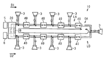
- the schematic diagram of the broadcast system which concerns on 1st Embodiment.
- FIG. 6 illustrates the operation of a branching isolator.
- the broadcast system 10 transmits a signal to the speaker 3 via the signal line 2.
- the broadcast system 10 is installed in a building and transmits audio information to the speakers 3 installed in each room.
- the audio information is not particularly limited.
- the voice information is contact information for notifying the public or a specific person, music sound information, disaster information, emergency evacuation information, and the like.
- the broadcast system 10 has a role of transmitting disaster information and emergency evacuation information when a disaster or the like occurs. If there is an abnormality in the broadcasting system 10 and the broadcastable area is limited, the role of the emergency notification can not be fully exerted. From such a thing, it is desirable for the broadcast system 10 to be provided with a function capable of suppressing a broadcast failure caused by an abnormality.
- the present technology is a technology relating to the suppression of broadcast failure.
- the broadcast failure indicates that it is not possible to transmit audio information to some or all of the speakers 3 based on a partial abnormality of the broadcast system 10.
- the broadcast system 10 according to the present embodiment will be described.
- the broadcast system 10 includes at least one broadcast output device 20 and a plurality of signal lines 2 connected to the broadcast output device 20.
- the plurality of signal lines 2 and an internal signal line 21 described later constitute one loop 1.
- the broadcast system 10 includes one or more isolators 40 attached to the signal line 2.
- the isolator 40 connects two signal lines 2 which are components of the loop 1.
- the speaker 3 is connected to the signal line 2 via the DC blocking filter 4.
- the direct current cut filter 4 is composed of, for example, a capacitor.
- the signal line 2 includes a pair of wires. Specifically, the signal line 2 includes the first wiring 2a and the second wiring 2b. The first wiring 2a is at a higher potential than the second wiring 2b, and the second wiring 2b is at a lower potential than the first wiring 2a. The first wiring 2a and the second wiring 2b are insulated from the ground.
- the broadcast output device 20 outputs output signals to the loop 1 in two directions.
- the broadcast output device 20 has a signal line (hereinafter, “internal signal line 21”) that constitutes a part of the loop 1.
- internal signal line 21 a portion other than the internal signal line 21 in the broadcast output device 20 is referred to as a loop main portion 1m.
- the broadcast output device 20 includes two terminals (hereinafter, “first terminal 31” and “second terminal 32”) connected to the signal line 2 of the loop body 1 m. The first terminal 31 and the second terminal 32 are connected by the internal signal line 21 in the broadcast output device 20.
- the broadcast output device 20 includes a power supply circuit 23, a ground fault detection unit 24, and a control unit 25.
- the power supply circuit 23 and the control unit 25 can be configured as an external device externally attached to the broadcast output device 20.
- the ground fault detection unit 24 may be omitted.
- the power supply circuit 23 generates a DC voltage of a first potential and a DC voltage of a second potential lower than the first potential based on the external power supply 5.
- the DC voltage of the first potential is input to the first wiring 21 a of the internal signal line 21.
- the DC voltage of the second potential is input to the second wiring 21 b of the internal signal line 21.
- the internal signal line 21 and the power supply circuit 23 are connected via an AC blocking filter 26 that blocks AC components.
- the AC blocking filter 26 prevents the AC component of the output signal (see below) transmitted to the internal signal line 21 from entering the power supply circuit 23 and suppresses the abnormal operation of the power supply circuit 23.
- the control unit 25 controls a loop connection switch 28 (see below) and a display unit (not shown).
- the control unit 25 outputs a display instruction signal to the display unit based on receiving various signals (first to third abnormality notification signals shown below).
- the display unit operates in a predetermined display mode (for example, lighting of a plurality of lamps) in accordance with a display instruction signal of the control unit 25.
- the manager of the broadcast system 10 can grasp the abnormality of the broadcast system 10 by the display mode of the display unit.
- the ground fault detection unit 24 detects that there is a short circuit between the first wiring 21 a and the ground and that there is a short circuit between the second wiring 21 b and the ground. When the ground fault detection unit 24 detects at least one of these short circuits, the ground fault detection unit 24 outputs a first abnormality notification signal indicating occurrence of a ground fault to the control unit 25.
- An input device 6 is connected to the broadcast output device 20.
- the input device 6 inputs a predetermined input signal to the broadcast output device 20.
- the input signal includes an audio signal corresponding to the above-mentioned audio information and a mechanical signal such as a tone signal.
- the pilot alternating signal described later is an example of a mechanical signal.
- the pilot alternating signal has a frequency outside the audible range or near the limit of the audible range.
- the pilot AC signal is configured as, for example, a 40 kHz or 20 kHz signal.
- the input signal is input to the internal signal line 21 through the noise cut filter 27.
- the input signal includes a first input signal transmitted to the first wiring 21 a and a second input signal transmitted to the second wiring 21 b.
- the first input signal includes an alternating current component
- the second input signal does not include an alternating current component.
- the input signal and the DC voltage are superimposed. That is, in the internal signal line 21, the first input signal and the direct current voltage of the first potential are superimposed, and the second input signal and the direct current voltage of the second potential are superimposed to form an output signal.
- the output signal is transmitted through the internal signal line 21 in two directions, a first direction D1 and a second direction D2 opposite to the first direction D1.
- An output signal in the first direction D1 is output from the first terminal 31, and an output signal in the second direction D2 is output from the second terminal 32.
- the broadcast output device 20 further includes a first switch 33, a second switch 36, a first short circuit detector 34, and a second short circuit detector 37. Furthermore, the broadcast output device 20 includes a loop connection switch 28. The first switch 33, the second switch 36, and the loop connection switch 28 are provided on the internal signal line 21.
- a loop connection switch 28 is provided between the first terminal 31 and the second terminal 32 in the internal signal line 21.
- the loop connection switch 28 connects “on” to connect the first terminal 31 and the second terminal 32 in the internal signal line 21 and disconnects between the first terminal 31 and the second terminal 32 (signal transmission is And "off" to be in a shut-off state.
- the loop connection switch 28 closes and opens the loop 1 by switching on and off.
- the loop connection switch 28 connects the switch 28 a that connects or disconnects the first wires 21 a and 21 a of the internal signal line 21 and the second wire 21 b and 21 b of the internal signal line 21.
- a switch 28b for disconnecting see FIG. 2.
- An open detection unit 29 is provided between the first terminal 31 and the loop connection switch 28 in the internal signal line 21.
- the open detection unit 29 detects whether or not the loop 1 is open.
- the release detection unit 29 operates at a predetermined step of “release detection processing” described later performed by the control unit 25 and detects release of the loop 1.
- "Open” indicates a state in which at least one of the first wiring 2a and the second wiring 2b of the signal line 2 constituting the loop 1 is cut. Hereinafter, this opening is called “loop opening”.
- the open detection unit 29 detects the potential difference between both ends of the resistor RD connected between the first wiring 2a and the second wiring 2b to determine whether the loop is open or not.
- a signal indicating that the loop is open hereinafter, referred to as “third error notification signal” is output to the control unit 25.
- the internal signal line 21 is provided with a first switch 33 and a second switch 36.
- the second switch 36 is disposed between the first switch 33 and the second terminal 32. That is, the first switch 33 is disposed closer to the first terminal 31 than the second switch 36.
- the second switch 36 is disposed closer to the second terminal 32 than the first switch 33.
- the first switch 33 and the second switch 36 are connected by an intermediate wiring 22 which is a component of the internal signal line 21.
- the loop connection switch 28 and the opening detection unit 29 described above are disposed between the first switch 33 and the first terminal 31.
- the first switch 33 connects between the first terminal 31 and the second switch 36 in the internal signal line 21 or disconnects between the first terminal 31 and the second switch 36. Specifically, in the first wiring 21 a of the internal signal line 21, the first switch 33 connects “on” the wiring on the first terminal 31 side and the intermediate wiring 22, and the wiring on the first terminal 31 side. It has an “off” for disconnecting from the intermediate wiring 22.
- the first switch 33 is turned “off” based on the detection of a short circuit by a first short circuit detector 34 described later.
- the first switch 33 turns “on” based on the fact that a first short detection unit 34 described later does not detect a short.
- the first short circuit detection unit 34 detects whether or not there is a short circuit in the signal line 2 on the first direction D1 side of the first switch 33.
- the short circuit indicates that the first wiring 2 a and the second wiring 2 b of the signal line 2 are in conduction.
- the first short circuit detection unit 34 includes a resistor RA connected to the first wiring 21 a in parallel with the first switch 33 and a first switch control unit 35.
- the potential of the first wiring 21a (potential on the first terminal 31 side) between the first switch 33 and the first terminal 31 is within a prescribed range (for example, the second potential (V) or more It is determined whether or not the range is equal to or less than a predetermined potential X lower than the first potential.
- the specified range indicates the potential range in the state in which the signal line 2 is shorted.
- the first switch control unit 35 determines that the short circuit has occurred. Then, the first switch control unit 35 turns off the first switch 33 and outputs a second abnormality notification signal to the control unit 25 when the detected potential is within the specified range (that is, there is a short circuit).
- the first switch control unit 35 turns on the first switch 33 when the detected potential is out of the specified range (that is, there is no short circuit).
- the second switch 36 has a structure similar to the first switch 33. Specifically, the second switch 36 is turned “off” on the internal signal line 21 based on the detection of a short circuit by the second short circuit detector 37 described later, and the second terminal 32 and the first switch 33 Between the second terminal 32 and the first switch 33 based on the fact that the second short circuit detection unit 37 does not detect a short circuit.
- the second short circuit detection unit 37 detects whether or not there is a short circuit in the signal line 2 on the second direction D2 side of the second switch 36.
- the second short circuit detection unit 37 includes a resistor RA connected to the first wire 21 a in parallel with the second switch 36 and a second switch control unit 38.
- the second switch control unit 38 determines whether the potential of the first wiring 21 a (potential on the second terminal 32 side) between the second switch 36 and the second terminal 32 is within a prescribed range.
- the specified range indicates the potential range in the state in which the signal line 2 is shorted.
- the second switch control unit 38 determines that a short circuit has occurred. Then, the second switch control unit 38 turns off the second switch 36 and outputs a second abnormality notification signal to the control unit 25 when the detected potential is within the prescribed range (that is, there is a short circuit).
- the second switch control unit 38 turns on the second switch 36 when the detected potential is out of the specified range (that is, there is no short circuit).
- both the first switch 33 and the second switch 36 are off, and the loop connection switch 28 is also off.
- the loop connection switch 28 is turned on.
- a DC voltage is input to the internal signal line 21 from the power supply circuit 23.
- a current flows in the resistor RA connected in parallel to the first switch 33.
- the signal line 2 on the first terminal 31 side is shorted to the first switch 33, the potential on the first terminal 31 side decreases, and the potential on the first terminal 31 side falls within the specified range.
- the first switch 33 is kept off by the first switch control unit 35.
- the second switch 36 operates in the same manner as the first switch 33.
- the signal line 2 on the side of the second terminal 32 is not short circuited, the potential on the side of the second terminal 32 is out of the specified range and the second switch 36 is turned on. It is transmitted to the signal line 2 on the two-direction D2 side.
- an input signal is input to the broadcast output device 20, an output signal is formed, so the output signal is output in the second direction D2.
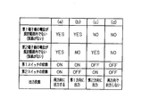
- the output form of the broadcast output device 20 will be described with reference to FIG. (A)
- the potential on the first terminal 31 side of the first switch 33 is not within the specified range (that is, there is no short circuit), and the potential on the second terminal 32 side of the second switch 36 is not within the specified range (that is, no short circuit is present) ),
- Output signals are outputted from two directions of the first direction D1 and the second direction D2.
- the isolator 40 connects the two signal lines 2 constituting the loop 1 as described above.
- the isolator 40 includes two terminals (hereinafter, “third terminal 42” and “fourth terminal 43”) to which the signal line 2 is connected.
- a signal line hereinafter, "internal signal line 41" connecting the third terminal 42 and the fourth terminal 43 in the isolator 40 is provided.
- the internal signal line 41 has a first wiring 41 a and a second wiring 41 b.
- the isolator 40 includes a separation switch 44, a third short circuit detector 45, and a fourth short circuit detector 47.
- the isolator 40 includes a power supply voltage generation circuit 49 that generates a power supply voltage.
- the separation switch 44 is provided on the first wiring 41 a of the internal signal line 41.
- the separation switch 44 connects the third terminal 42 and the fourth terminal 43 in the internal signal line 41 to “on” and disconnects the third terminal 42 and the fourth terminal 43 to “off”. Have.
- the separation switch 44 is turned “off” based on at least one of the third short circuit detector 45 and the fourth short circuit detector 47 detecting a short circuit.
- the separation switch 44 is turned “on” based on the fact that neither the third short detection unit 45 nor the fourth short detection unit 47 detects a short (see FIG. 5).
- the third short circuit detector 45 detects whether or not there is a short circuit in the part on the third terminal 42 side with respect to the separation switch 44.
- the third short circuit detection unit 45 includes a resistor RB connected to the first wiring 41 a in parallel with the separation switch 44 and a third switch control unit 46.
- the third switch control unit 46 determines whether or not the potential of the first wiring 41 a (potential on the third terminal 42 side) between the separation switch 44 and the third terminal 42 is within a specified range.
- the specified range indicates the potential range in the state in which the signal line 2 is shorted. When the potential on the third terminal 42 side with respect to the separation switch 44 is within the specified range, the third switch control unit 46 determines that a short circuit has occurred.
- the fourth short circuit detection unit 47 detects whether or not there is a short circuit in a portion on the fourth terminal 43 side with respect to the separation switch 44.
- the fourth short circuit detection unit 47 has the same structure as the third short circuit detection unit 45 except for the following point.
- the fourth short detection unit 47 includes a resistor RB connected to the first wiring 41 a in parallel with the separation switch 44, and a fourth switch control unit 48.
- the resistor RB is shared by the third short circuit detector 45 and the fourth short circuit detector 47.
- Power supply voltage forming circuit 49 generates a power supply voltage based on the output signal transmitted through signal line 2.
- the power supply voltage generated by the power supply voltage generation circuit 49 is supplied to the third short detection unit 45 and the fourth short detection unit 47 in the isolator 40.
- the power supply voltage formation circuit 49 has two input parts 49a and 49b. One input portion 49 a is connected to the first wiring 41 a between the separation switch 44 and the third terminal 42. The other input portion 49 b is connected to the first wiring 41 a between the separation switch 44 and the fourth terminal 43.
- the power supply voltage forming circuit 49 has the two input portions 49a and 49b, whereby the power supply voltage is formed regardless of the direction of transmission of the output signal.
- FIGS. 5A-5D illustrate the operation when an output signal is transmitted to the isolator 40 from at least one of two directions. At this time, since the power supply voltage is formed, the separation switch 44 operates.
- FIG. 5E shows the operation when the output signal is not transmitted to the isolator 40 from either of two directions. At this time, since the power supply voltage is not formed, the switch does not operate, and the separation switch 44 is kept off.
- the operation of the isolator 40 at startup of the broadcast system 10 will be described with reference to FIGS. 6 to 10.
- a case where there is a short circuit in the signal line 2 between the second isolator 40 and the third isolator 40 in the first direction D1 from the broadcast output device 20 will be described as an example.
- each switch of the broadcast output device 20 and the isolator 40 is "off".
- the loop connection switch 28 of the broadcast output device 20 is turned “on”.
- the first switch 33 and the second switch 36 of the broadcast output device 20 are "off”, and the separation switch 44 of the isolator 40 is "off".
- a DC voltage of a first potential is output to the first wiring 2 a of the signal line 2.
- the DC voltage is transmitted in the first direction D1 and the second direction D2.
- the potential on the third terminal 42 side of the separation switch 44 and the potential on the fourth terminal 43 side become values outside the prescribed range (values larger than the above-mentioned predetermined potential X larger than the second potential),
- the separation switch 44 is turned “on” by the operation of the third short circuit detection unit 45 and the fourth short circuit detection unit 47.
- the separation switch 44 of the second isolator 40 is maintained in the “off” state, whereby each isolator 40 on the first direction D1 side with respect to the second isolator 40 has the first direction D1.
- the DC voltage supplied from is not transmitted.
- a current flows in the short circuit portion SC of the loop 1 through at least one resistor RB, and a direct current voltage is not directly applied to the short circuit portion SC from the first direction D1.
- one of the potential on the third terminal 42 side and the potential on the fourth terminal 43 side of the separation switch 44 (potential near the short circuit portion SC) has a value within the prescribed range (value near the second potential) Become. Therefore, the third short circuit detection unit 45 or the fourth short circuit detection unit 47 determines that the short circuit has occurred, and the separation switch 44 is maintained in the "off" state.
- the separation switch 44 of the isolator 40 immediately before reaching the short circuit portion SC of the loop 1 in the second direction D2 is maintained in the “off” state.
- the direct current voltage supplied from the second direction D2 is not transmitted to each isolator 40.
- a current flows in the short circuit portion SC of the loop 1 via the at least one resistor RB, and direct voltage application to the short circuit portion SC from the second direction D2 is suppressed.
- each of the isolators 40 turns off the isolation switches 44 of the two isolators 40 sandwiching the short circuit portion SC of the loop 1.
- the short circuit portion SC of the loop 1 is substantially isolated from the range of the output signal transmission of the broadcast system 10. Then, the direct current voltage is not directly applied to the short circuit portion SC of the loop 1. In this manner, the flow of the overcurrent in the short circuit portion SC is suppressed.
- the broadcast output apparatus 20 and the isolator 40 perform short circuit detection as described above when power is supplied. Therefore, when the broadcast output device 20 and the isolator 40 detect a short circuit, the short circuit portion SC is isolated because the switch of the device that detects the short circuit is turned “off”. Thus, according to the broadcast system 10 of the present embodiment, a short circuit is always detected as long as power is supplied. And, when a short circuit is detected, the short circuit portion SC is automatically isolated.
- the isolator 40 detects a short circuit on both sides of the separation switch 44. Further, as described above, the broadcast output device 20 detects a short circuit on both sides of the first switch 33 and the second switch 36. By this configuration, each signal line 2 is sandwiched by two switches on the loop 1. Then, in each signal line 2, a short circuit is detected based on each of the output signals input from both directions (the first direction D1 and the second direction D2). When a short circuit occurs in the signal line 2, a short circuit is detected on both sides of the short circuit portion SC of the signal line 2, and switches on both sides of the signal line 2 are turned off. In this way, the signal line 2 including the short circuit portion SC is isolated from the loop 1.
- the second function of the isolator 40 will be described. Since the power supply voltage is not generated in the separation switch 44 of the isolator 40 before the start of the broadcast system 10, the third terminal 42 and the fourth terminal 43 are in a non-connected state. When the broadcast system 10 is activated, an output signal is output from the broadcast output device 20, and a power supply voltage is formed in the isolator 40 based on the output signal, and the separation switch 44 becomes operable. Further, the separation switch 44 connects between the third terminal 42 and the fourth terminal 43 based on the fact that the third short circuit detection unit 45 and the fourth short circuit detection unit 47 do not detect a short circuit.
- the isolator 40 is activated sequentially from the side closer to the broadcast output device 20 starting from the broadcast output device 20 at the time of startup, and a short circuit of the signal line 2 is detected sequentially from the side closer to the broadcast output device 20 Ru. If a short is detected, the signal line 2 with the short is isolated. In this manner, the flow of the overcurrent in the short circuit portion SC is suppressed at the time of start-up.
- the open detection process will be described with reference to FIGS. 11 and 12.
- the release detection process is a process for detecting whether or not the loop 1 is released.
- the release detection process is periodically executed by the control unit 25.
- the control unit 25 executes the release detection process at intervals of several tens of seconds.
- the control unit 25 executes the following steps S1 to S4 in the release detection process.
- step S1 the control unit 25 turns the loop connection switch 28 "off".
- the output signal is output only in the second direction D2.
- the output signal output from the second terminal 32 is input to the first terminal 31 via the loop 1.
- an output signal returned from the broadcast output device 20 and returned to the broadcast output device 20 is referred to as a "return signal”.
- the open detection unit 29 detects the presence or absence of the “return signal”.
- the open detection unit 29 does not detect the "return signal”.
- the release detection unit 29 outputs a signal indicating the presence or absence of the “return signal” to the control unit 25.
- step S ⁇ b> 2 the control unit 25 determines whether there is a “return signal” based on the detection result of the “return signal” of the open detection unit 29.
- the control unit 25 outputs a third abnormality notification signal indicating the loop open to the display unit in step S3.
- step S4 the loop connection switch 28 is turned “on” in step S4, and the release detection process is ended.
- step S2 when there is a "return signal” in step S2 (when the loop 1 is not opened)
- the control unit 25 turns on the loop connection switch 28 in step S4, and ends the opening detection process.
- the broadcast output device 20 outputs an output signal in the first direction D1 and the second direction D2 as described above. Therefore, when the loop 1 is open, an output signal is transmitted from the first direction D1 to one line LA between the broadcast output device 20 and the open portion OA in the loop 1 and the other line LB , And an output signal from the second direction D2. In this way, the output signal is transmitted to all the lines LA and LB.
- loop 1 has two opens, no output signal is transmitted between the two open parts OA, and an output signal is transmitted to the other part between the two open parts OA.
- the portion where the output signal is not transmitted can be reduced compared to a broadcast output device that outputs the output signal in only one direction.
- the broadcast output device 20 outputs an output signal in the first direction D1 and the second direction D2 of the loop 1. According to this configuration, since signals are transmitted from the broadcast output device 20 to the open portion OA from two directions, the range in which the signal is not transmitted in the loop 1 can be reduced when part of the loop 1 is open. . Also, according to the broadcast output device 20, no communication device is required to obtain this effect.
- the broadcast output device 20 outputs an output signal from one of the first direction D1 and the second direction D2 at a predetermined time (for example, periodically). Then, based on whether the “return signal” returned via the loop 1 is detected by the broadcast output device 20, it is determined whether the loop 1 has an abnormality. According to this configuration, it is possible to easily detect whether or not the loop 1 has an abnormality (in the present embodiment, it is open).
- the broadcast output device 20 forms an output signal to be output to the loop 1 by superimposing the input signal and the DC voltage.
- the isolator 40 operates based on the output signal to detect a short circuit of the signal line 2 connected to the isolator 40, and when there is no short circuit, connects the two signal lines 2 connected to the isolator 40, and the short circuit At one time, the two signal lines 2 connected to the isolator 40 are disconnected.
- the isolator 40 operates based on the power of the output signal to detect a short circuit. For this reason, the external power supply for operating the isolator 40 is unnecessary. Then, when there is a short circuit, the two signal lines 2 connected to the isolator 40 are disconnected. As a result, it can be prevented that the output signal continues to be transmitted to the wiring in which the short circuit occurs. In this way, when a short circuit occurs in the loop 1, the short circuit can be easily isolated.
- the first switch 33 of the broadcast output device 20 disconnects the first terminal 31 and the second switch 36 based on the detection of the short circuit by the first short circuit detector 34, and detects the first short circuit.
- the first terminal 31 and the second switch 36 are connected based on the fact that the unit 34 does not detect a short circuit.
- the second switch 36 of the broadcast output device 20 disconnects the second terminal 32 from the first switch 33 based on the second short circuit detection unit 37 detecting a short circuit, and the second short circuit detection unit 37
- the second terminal 32 and the first switch 33 are connected based on not detecting a short circuit. According to this configuration, when there is a short circuit in the signal line 2 connected to the broadcast output device 20, transmission of the output signal to the short circuit portion SC can be suppressed.
- the separation switch 44 of the isolator 40 detects a short between the third terminal 42 and the fourth terminal 43 based on at least one of the third short circuit detector 45 and the fourth short circuit detector 47 detecting a short circuit. Connect Further, the separation switch 44 connects the third terminal 42 and the fourth terminal 43 based on the fact that neither the third short detection unit 45 nor the fourth short detection unit 47 detects a short. According to this configuration, when there is a short circuit in the signal line 2 connected to the isolator 40, transmission of the output signal to the short circuit portion SC can be suppressed.
- the isolator 40 disconnects the third terminal 42 from the fourth terminal 43 when the output signal does not reach the isolator 40. According to this configuration, the separation switch 44 is “off” before the broadcast system 10 is activated. When the output signal is input to the isolator 40, the isolator 40 operates. With such a configuration, it is possible to suppress the flow of current to the short circuit portion SC when the broadcast system 10 is started.
- the broadcast system 11 according to the second embodiment will be described with reference to FIGS. 14 to 18.
- the broadcast system 11 according to the second embodiment includes one loop 1 and a branch signal line 7 branched from the loop 1.
- the signal line 2 and the branch signal line 7 constituting the loop 1 are connected via the branch isolator 50.
- the broadcast system 11 according to the second embodiment is different from that of the first embodiment in two points of having the branch signal line 7 and having the branch isolator 50.
- detection of an abnormality in the branch signal line 7 will be described.
- the same components as the components shown in the first embodiment will be assigned the same reference numerals as the symbols given to the components of the first embodiment.
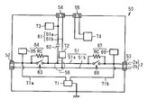
- FIG. 15 is a circuit diagram of the branching isolator 50.
- the branching isolator 50 connects the signal line 2 forming the loop 1 and the branching signal line 7.
- the branching isolator 50 has two terminals (hereinafter, “first loop terminal 52” and “second loop terminal 53”) to which the signal line 2 forming the loop 1 is connected, and a terminal to which the branch signal line 7 is connected. (Hereinafter, "branch terminal 54").
- a signal line hereinafter, “internal signal line 51” that connects the first loop terminal 52 and the second loop terminal 53 in the branch isolator 50 is provided.
- the internal signal line 51 has a first wiring 51a and a second wiring 51b.
- a signal line (hereinafter, “internal branching signal line 61”) connecting the branching terminal 54 and the internal signal line 51 is provided.
- the internal branch signal line 61 has a first wire 61a and a second wire 61b.
- a portion where the internal signal line 51 and the internal branch signal line 61 are connected is referred to as a “branch portion 56”.
- the branching isolator 50 includes a branching end terminal 55 to which the end of the branching signal line 7 is connected.
- the first wiring 61 a of the internal branch signal line 61 is provided with a DC blocking filter 62 for blocking a DC component.
- the DC blocking filter 62 blocks the DC component of the output signal and passes the AC component.
- the direct current cut filter 62 passes signals of a frequency including an audible range and a range before and after the audible range. That is, only alternating current is transmitted to the branch signal line 7. For this reason, the speaker 3 which does not have a DC blocking filter can be connected to the branch signal line 7.
- the branch isolator 50 includes a first separation switch 63, a second separation switch 66, a fifth short detection unit 64, and a sixth short detection unit 67.
- the branching isolator 50 includes a power supply voltage formation circuit 71.
- the branch isolator 50 is a branch short circuit detection unit 72 that detects the current of the branch signal line 7, a pilot AC detection unit 73 that detects a pilot AC signal described later, and a first wire 7 a of the branch signal line 7.
- a branch voltage detection unit 74 that detects a voltage difference between the second wiring 7b and the second wiring 7b.
- the first separation switch 63 and the second separation switch 66 are provided on the first wiring 51 a of the internal signal line 51.
- the first separation switch 63 is provided between the first loop terminal 52 and the branch portion 56.
- the second separation switch 66 is provided between the second loop terminal 53 and the branch portion 56. That is, the first separation switch 63 and the second separation switch 66 are disposed to sandwich the branch portion 56.
- the first separation switch 63 has “on” for connecting the first loop terminal 52 and the branch portion 56 and “off” for disconnecting the first loop terminal 52 from the branch portion 56.
- the second separation switch 66 has “on” for connecting the second loop terminal 53 and the branch 56 and “off” for disconnecting the second loop terminal 53 from the branch 56.
- the first separation switch 63 is turned “off” regardless of the detection state of the fifth short circuit detection unit 64 based on the detection of a short circuit by the branch short circuit detection unit 72 described later.
- the first separation switch 63 is turned “off” based on the branch short circuit detector 72 described later not detecting a short circuit and the fifth short circuit detector 64 described later detecting a short circuit.
- the first separation switch 63 is turned “on” based on the branch short circuit detector 72 described later not detecting a short circuit and the fifth short circuit detector 64 described later not detecting a short circuit.
- the second separation switch 66 is turned “off” regardless of the detection state of the sixth short circuit detection unit 67 based on the detection of a short circuit by the branch short circuit detection unit 72 described later.
- the second separation switch 66 is turned “off” based on the branch short circuit detection unit 72 described later not detecting a short circuit and the sixth short circuit detection unit 67 detecting a short circuit.
- the second separation switch 66 is turned “on” based on the fact that a branch short circuit detection unit 72 described later does not detect a short circuit and the sixth short circuit detection unit 67 does not detect a short circuit.
- the fifth short circuit detector 64 detects whether or not there is a short circuit in the portion on the first loop terminal 52 side with respect to the first separation switch 63.
- the fifth short circuit detector 64 includes a resistor RC connected to the first wire 51 a in parallel with the first separation switch 63 and a fifth switch controller 65.
- the fifth switch control unit 65 determines whether the potential of the first wiring 51a (potential on the first loop terminal 52 side) between the first separation switch 63 and the first loop terminal 52 is within a prescribed range. Do.
- the specified range indicates the potential range in the state in which the signal line 2 is shorted. When the potential on the first loop terminal 52 side is within the prescribed range, the fifth switch control unit 65 determines that a short circuit has occurred.
- the sixth short circuit detection unit 67 detects whether or not there is a short circuit in the portion on the second loop terminal 53 side with respect to the second separation switch 66.
- the sixth short circuit detector 67 includes a resistor RC connected in parallel to the second separation switch 66 to the first wire 51 a and a sixth switch controller 68.
- the sixth switch control unit 68 determines whether or not the potential of the first wiring 51a (potential on the second loop terminal 53 side) between the second separation switch 66 and the second loop terminal 53 is within a prescribed range. Do.
- the specified range indicates the potential range in the state in which the signal line 2 is shorted. When the potential on the second loop terminal 53 side is within the specified range, the sixth switch control unit 68 determines that a short circuit has occurred.
- the power supply voltage forming circuit 71 generally has the same structure as that shown in the first embodiment. Specifically, power supply voltage formation circuit 71 forms a power supply voltage based on the output signal transmitted through signal line 2.
- the power supply voltage generated by the power supply voltage forming circuit 71 is the fifth short circuit detector 64, the sixth short circuit detector 67, the branch short circuit detector 72, the pilot AC detector 73, and the branch voltage detector 74 in the branch isolator 50.
- Supplied to The power supply voltage forming circuit 71 has two inputs. One input portion 71 a is connected to the first wiring 51 a between the first separation switch 63 and the first loop terminal 52.
- the other input portion 71 b is connected to the first wiring 51 a between the second separation switch 66 and the second loop terminal 53.
- the power supply voltage forming circuit 71 has the two input parts 71a and 71b, so that the power supply voltage is formed by the power supply voltage forming circuit 71 regardless of the transmission direction of the output signal.
- the branch short circuit detection unit 72 detects the current of the internal branch signal line 61, and determines whether the current is within a specified range.
- the specified range indicates the current range when the branch signal line 7 is shorted.
- the branch short circuit detector 72 determines that a short circuit has occurred.
- both the first separation switch 63 and the second separation switch 66 are turned “off”.
- the pilot AC detection unit 73 detects a pilot AC signal. When the pilot AC detection unit 73 detects a pilot AC signal, the pilot AC detection unit 73 notifies the branch voltage detection unit 74 that the pilot AC signal has been detected.
- the branch voltage detection unit 74 detects the potential difference between the first wiring 7a and the second wiring 7b at the end of the branch signal line 7, and the potential difference is within the prescribed range. It is determined whether the The above-mentioned specified range indicates the voltage range when the branch signal line 7 is open. Then, the branch voltage detection unit 74 determines that the branch signal line 7 is open when the potential difference is within the specified range. When detecting the open state, the branch voltage detection unit 74 visibly displays a predetermined display (for example, lighting of a lamp) indicating that the open state is detected. Further, when detecting the open state, the branch voltage detection unit 74 turns “off” only one of the first separation switch 63 and the second separation switch 66.
- a predetermined display for example, lighting of a lamp
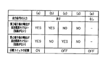
- FIGS. 16A to 16E show the case where the output signal is transmitted to the branching isolator 50 from at least one of the two directions.
- the switch since the power supply voltage is formed, the switch operates.
- (a) to (e) in FIG. 16 (a) to (d) are the first separation switch 63 and the second separation switch when the current of the branch signal line 7 is not within the specified range (that is, there is no short circuit).
- the operation of 66 is shown.
- FIG. 16F shows the case where the output signal is not transmitted to the branching isolator 50 from any of the two directions. At this time, since the power supply voltage is not formed, the switch does not operate and is kept off.
- (A) to (d) are states under the precondition that the current of the branch signal line 7 is not within the specified range (that is, there is no short circuit in the branch signal line 7).
- (A) In the above premise, when the potential on the first loop terminal 52 side of the first separation switch 63 is not within the specified range (that is, there is no short circuit), the first separation switch 63 is turned on. Further, under the above premise, when the potential on the second loop terminal 53 side of the second separation switch 66 is not within the specified range (that is, there is no short circuit), the second separation switch 66 is turned on. At this time, the two signal lines 2 connected to the branch isolator 50 are connected, and the two signal lines 2 and the branch signal line 7 are connected. Thus, the branch signal line 7 is connected to the loop 1 via the first loop terminal 52 and the second loop terminal 53 ("both connections").
- branching isolator 50 The operation of the branching isolator 50 at startup of the broadcast system 11 will be described with reference to FIGS. 17 and 18.
- a case where there is a short circuit in the signal line 2 on the first direction D1 side with respect to the branching isolator 50 will be described as an example.
- each switch of the broadcast output device 20, the isolator 40 and the branching isolator 50 is "off".
- the control unit 25 turns on the loop connection switch 28 of the broadcast output device 20.
- the control unit 25 outputs an output signal on which the pilot AC signal is superimposed from the broadcast output device 20.
- the pilot alternating signal is formed, for example, by the input device 6.
- the pilot AC signal is a signal used for open inspection of the branch signal line 7.
- the DC voltage is transmitted in the first direction D1 and the second direction D2. Then, for each of the isolators 40 that constitute the loop 1, a short circuit is sequentially detected in the first direction D1. When a short circuit is not detected by the isolator 40, the separation switch 44 of the isolator 40 is turned “on", and a DC voltage is transmitted to the adjacent isolator 40. Similarly, a short circuit is sequentially detected in the second direction D2 for each of the isolators 40 constituting the loop 1.
- the separation switch 44 of the isolator 40 immediately before the branch isolator 50 is turned “on” in the first direction D1
- a DC voltage is transmitted to the branch isolator 50.
- the power supply voltage forming circuit 71 of the branching isolator 50 operates to form a power supply voltage.
- the fifth short circuit detector 64, the sixth short circuit detector 67, the branch short circuit detector 72, the branch voltage detector 74, and the pilot alternating current detector 73 operate.
- the DC voltage is transmitted to the branching isolator 50, the DC voltage is applied to the branch signal line 7. Since the direct current cut filter 62 is provided in the internal branch signal line 61, only the AC component of the output signal is transmitted to the branch signal line 7.
- the pilot AC detection unit 73 detects a pilot AC signal. Based on this detection, the branch voltage detection unit 74 starts the detection of opening of the branch signal line 7.
- the branch voltage detection unit 74 detects the open state, for example, a display lamp provided in the branch isolator 50 is turned on. Thereby, the release is notified. Further, when the branch voltage detection unit 74 detects the open state, only one of the first separation switch 63 and the second separation switch 66 is turned “off”. Thus, the broadcast output device 20 can detect that the branch signal line 7 is open (see “open detection process” described later).
- the branch short circuit detector 72 starts detecting a short circuit in the branch signal line 7.
- the branch short circuit detection unit 72 detects a short circuit, as described above, the first separation switch 63 and the second separation switch 66 are both kept “off”.
- the switch command based on the "short circuit detection” by the branch short circuit detection unit 72 is a switch command based on the "short circuit detection” of the fifth short circuit detection unit 64 and the switch command based on the "short circuit detection” of the sixth short circuit detection unit 67.
- the sixth short circuit detection unit 67 determines that the short circuit has occurred and keeps the second separation switch 66 "off".
- the second separation switch 66 is maintained in the “off” state, so that the DC voltage supplied from the first direction D1 is applied to each isolator 40 on the first direction D1 side of the branch isolator 50. It will not be transmitted.
- a current flows in the short circuit portion SC of the loop 1 through at least two resistances RC and RC (see the broken line), and the direct current voltage is prevented from being applied to the short circuit portion SC directly from the first direction D1. Be done.
- the fifth short circuit detector 64 does not detect a short circuit, and turns the first separation switch 63 "on". Then, the branch signal line 7 is connected to the loop 1 through the first loop terminal 52. Thus, the alternating current of the output signal is transmitted to the branch signal line 7 (see FIG. 18).
- the operation of the switch group on the second direction D2 side in the loop 1 conforms to the operation of the switch group on the second direction D2 side in the loop 1 described in the first embodiment. Therefore, in this example, the separation switch 44 of the isolator 40 adjacent to the first direction D1 side with respect to the branching isolator 50 is kept off.
- the second separation switch 66 of the branch isolator 50 and the separation switch 44 of the isolator 40 sandwiching the short circuit portion SC of the loop 1 are turned “off”.
- the short circuit part SC of the loop 1 is substantially isolated from the range of the output signal transmission of the broadcast system 11.
- the direct current voltage is not directly applied to the short circuit portion SC of the loop 1. In this manner, the flow of the overcurrent in the short circuit portion SC is suppressed.
- each step of the release detection process is the same as that of the first embodiment.
- the operation of the open detection process will be described by taking the case where the branch signal line 7 is open as an example.
- the flowchart is the same as the flowchart shown in FIG.
- step S1 the control unit 25 turns the loop connection switch 28 "off". Thus, the output signal is output only in the second direction D2. Then, the output signal output from the second terminal 32 is input to the first terminal 31 via the loop 1.
- the branch signal line 7 When the branch signal line 7 is open, the "return signal” is not detected. This is because, as described above, when the branch signal line 7 is detected open, one of the first separation switch 63 and the second separation switch 66 is turned “off” in the branch isolator 50.
- step S ⁇ b> 2 the control unit 25 determines whether there is a “return signal” based on the detection result of the “return signal” of the open detection unit 29.
- the control unit 25 outputs a third abnormality notification signal indicating open loop to the display unit in step S3.
- the control unit 25 turns on the loop connection switch 28 in step S4, and ends the open detection process. As described above, it is detected that the branch signal line 7 is open by the same process as the open detection process shown in the first embodiment.
- the first separation switch 63 of the branching isolator 50 disconnects the first loop terminal 52 from the branching unit 56 based on the fifth short circuit detection unit 64 detecting a short circuit, and detects the fifth short circuit.
- the first loop terminal 52 and the branch portion 56 are connected based on the fact that the portion 64 does not detect a short circuit.
- the second separation switch 66 of the branching isolator 50 disconnects the second loop terminal 53 from the branching unit 56 based on the detection of the short circuit by the sixth short circuit detecting unit 67, and the sixth short circuit detecting unit 67
- the second loop terminal 53 and the branch portion 56 are connected based on the fact that the short circuit is not detected. According to this configuration, when there is a short circuit in the signal line 2 connected to the branching isolator 50, transmission of the output signal to the short circuit portion SC can be suppressed.
- the first separation switch 63 Based on the branch short circuit detection unit 72 of the branch isolator 50 detecting a short circuit of the branch signal line 7, the first separation switch 63 has the first loop terminal 52 and the branch portion 56 of the branch signal line 7.
- the second separation switch 66 disconnects the connection between the second loop terminal 53 and the branch portion 56 of the branch signal line 7. According to this configuration, when a short circuit is detected in branch signal line 7, branch signal line 7 is isolated from loop 1. This can suppress transmission of the output signal to the short circuit portion SC.
- the branching isolator 50 is provided with the DC blocking filter 62 disposed on the internal branching signal line 61 and blocking a DC component. According to this configuration, the branch signal line 7 can cut off the DC component. Thereby, the speaker 3 which is not provided with a capacitor for blocking a direct current component can be connected to the branch signal line 7.
- the broadcast output device 20 outputs a pilot AC signal for detecting the opening of the branch signal line 7.
- the branch isolator 50 detects the open of the branch signal line 7 when receiving the pilot AC signal. If any signal is not input to the branch signal line 7, the open of the branch signal line 7 can not be accurately detected. The reason for this is that there is no large difference between the potential difference when the signal is not inputted to the branch signal line 7 and the potential difference when the signal is open. In this respect, according to the above configuration, since the opening of the branch signal line 7 is detected when the pilot AC signal is received, it is possible to suppress the erroneous detection of the detection of the opening of the branch signal line 7.
- the branching isolator 50 further includes the power supply voltage generation circuit 71.
- the first separation switch 63 disconnects between the first loop terminal 52 and the branch portion 56 of the branch signal line 7 when the power supply voltage is not formed (the first separation switch 63 is “off”), and the second separation switch 63
- the separation switch 66 disconnects between the second loop terminal 53 and the branch portion 56 of the branch signal line 7 when the power supply voltage is not formed (the second separation switch 66 is “off”).
- both the first separation switch 63 and the second separation switch 66 are "off".
- the branch isolator 50 can detect a short circuit by inputting an output signal to the branch isolator 50. Thus, it is possible to suppress the flow of current to the short circuit portion SC when the broadcast system 11 is started.
- the broadcast output device 20 outputs an output signal from one of the first direction D1 and the second direction D2. Then, based on whether or not the return signal to be returned through the loop 1 is detected by the broadcast output device 20, it is determined whether or not there is an abnormality in the loop 1. According to this configuration, it can be detected whether or not there is an abnormality in the loop 1 (in the present embodiment, the open of the branch signal line 7).
- the configurations of the broadcast output device 20 and the broadcast systems 10 and 11 are not limited to the examples of the embodiment.
- the embodiments listed above can be modified as follows.
- the pilot AC signal is formed by the input device 6, but the pilot AC signal may be formed in the broadcast output device 20.
- line 2 is comprised by a pair of wiring, the structure of the signal wire
- the signal line 2 may be configured by one conductor. Also, the signal line 2 may be configured by a coaxial cable.
- D1 first direction
- D2 second direction
- LA line
- LB line
- OA open part
- RA resistance
- RB resistance
- RC resistance
- RD resistance
- SC shorted part
- 1 loop
- DESCRIPTION OF SYMBOLS 1m ... Loop main-body part 2 ... Signal line, 2a ... 1st wiring, 2b ... 2nd wiring, 3 ... Speaker, 4 ... DC blocking filter, 5 ... External power supply, 6 ... Input device, 7 ... Branch signal line, 7a ... 1st wiring, 7b ... 2nd wiring, 10 ... broadcast system, 11 ... broadcast system, 20 ... broadcast output device, 21 ... internal signal line, 21a ... 1st wiring, 21b ...
Landscapes
- Physics & Mathematics (AREA)
- Engineering & Computer Science (AREA)
- Acoustics & Sound (AREA)
- Signal Processing (AREA)
- Health & Medical Sciences (AREA)
- General Health & Medical Sciences (AREA)
- Otolaryngology (AREA)
- Computer Security & Cryptography (AREA)
- General Physics & Mathematics (AREA)
- Alarm Systems (AREA)
Abstract
放送システム(10)は、スピーカー(3)に信号を伝達するものであり、複数の信号線(2)により構成される1つのループ(1)と、ループ(1)を構成する信号線(2)の間に配置される1または複数のアイソレータ(40)と、ループ(1)に出力信号を出力する放送出力装置(20)とを備える。放送出力装置(20)は、入力信号と直流電圧とを重畳することによりループ(1)に出力する出力信号を形成する。アイソレータ(40)は、出力信号に基づいて動作して、アイソレータ(40)に接続される信号線(2)の短絡を検出し、短絡がないとき、アイソレータ(40)に接続される複数の信号線(2)を接続し、短絡があるときは、アイソレータ(40)に接続される複数の信号線(2)を非接続にする。
Description
本発明は、スピーカーが接続される信号線に信号を出力する放送システムに関する。
放送システムにおいて信号線に異常があるとき、放送システムにおいて異常が発生していない信号線に放送用の信号を伝達する技術が知られている。
例えば、特許文献1に記載の技術では、信号線に開放または短絡があるとき、当該信号線を隔離する。
例えば、特許文献1に記載の技術では、信号線に開放または短絡があるとき、当該信号線を隔離する。
ところで、特許文献1に記載の技術では、モデム等の通信装置を用いている。このため、既存の放送システムにこの技術を導入することは難しい。
本発明の目的は、信号線に短絡が発生したとき、簡単に短絡部分を隔離できる放送システムを提供することにある。
本発明の目的は、信号線に短絡が発生したとき、簡単に短絡部分を隔離できる放送システムを提供することにある。
(1)本発明の一側面に従う放送出力装置は、スピーカーに信号を伝達する放送システムであって、少なくとも1つの前記スピーカーが接続可能な複数の信号線により構成される1つのループと、前記ループを構成する信号線の間に配置される1または複数のアイソレータと、前記ループに出力信号を出力する放送出力装置とを備え、前記放送出力装置は、入力信号と直流電圧とを重畳することにより前記ループに出力する出力信号を形成し、前記アイソレータは、前記出力信号に基づいて動作して、前記アイソレータに接続される前記信号線の短絡を検出し、前記短絡がないとき、前記アイソレータに接続される複数の信号線を接続し、前記短絡があるとき、前記アイソレータに接続される複数の信号線を非接続にする。
この構成によれば、アイソレータは、出力信号の電力に基づいて動作し、短絡を検出する。そして、短絡がある場合、アイソレータに接続される複数の信号線を非接続にする。これにより、短絡が発生している配線に、出力信号が伝達され続けることを抑止できる。このようにして、簡単に、ループにおいて短絡が発生したとき、当該短絡部分を簡単に隔離できる。
(2)上記放送システムにおいて、前記放送出力装置は、前記ループの信号線が接続される第1端子及び第2端子と、前記放送出力装置内で前記第1端子と前記第2端子とを繋ぐ内部信号線に設けられる第1スイッチと、前記第1スイッチと前記第2端子との間に設けられ前記第1スイッチに接続される第2スイッチと、前記第1スイッチに対して前記第1端子側の部分の短絡を検出する第1短絡検出部と、前記第2スイッチに対して前記第2端子側の部分の短絡を検出する第2短絡検出部とを備え、前記第1スイッチは、前記第1短絡検出部が短絡を検出することに基づいて前記第1端子と前記第2スイッチとの間を非接続にし、前記第1短絡検出部が短絡を検出しないことに基づいて前記第1端子と前記第2スイッチとを接続し、前記第2スイッチは、前記第2短絡検出部が短絡を検出することに基づいて前記第2端子と前記第1スイッチとの間を非接続にし、前記第2短絡検出部が短絡を検出しないことに基づいて前記第2端子と前記第1スイッチとを接続する。この構成によれば、放送出力装置に接続される信号線に短絡が検出されるとき、当該短絡部分に出力信号が伝わることを抑制できる。
(3)上記放送システムにおいて、前記アイソレータは、第3端子及び第4端子と、前記第3端子及び前記第4端子を接続する内部信号線に設けられる分離スイッチと、前記分離スイッチに対して前記第3端子側の部分の短絡を検出する第3短絡検出部と、前記分離スイッチに対して前記第4端子側の部分の短絡を検出する第4短絡検出部とを備え、前記分離スイッチは、前記第3短絡検出部及び前記第4短絡検出部の少なくとも一方が短絡を検出することに基づいて前記第3端子と前記第4端子との間を非接続にし、前記第3短絡検出部及び前記第4短絡検出部のいずれもが短絡を検出しないことに基づいて前記第3端子と前記第4端子とを接続する。この構成によれば、アイソレータに接続される信号線に短絡があるとき、当該短絡部分に出力信号が伝わることを抑制できる。
(4)上記放送システムにおいて、前記分離スイッチは、前記アイソレータに前記出力信号が到達していないとき前記第3端子と前記第4端子との間を非接続にする。
この構成によれば、放送システムの起動前、第3端子と前記第4端子との間は非接続である。アイソレータに出力信号が入力されることにより、アイソレータが動作する。このような構成により、放送システムの起動時に、短絡部分に電流が流れることを抑制できる。
この構成によれば、放送システムの起動前、第3端子と前記第4端子との間は非接続である。アイソレータに出力信号が入力されることにより、アイソレータが動作する。このような構成により、放送システムの起動時に、短絡部分に電流が流れることを抑制できる。
(5)上記放送システムは、前記ループと前記ループから分岐する分岐信号線との間に接続される分岐アイソレータをさらに備え、前記分岐アイソレータは、前記ループの信号線が接続される第1ループ端子及び第2ループ端子と、前記分岐信号線が接続される分岐端子と、前記第1ループ端子と前記分岐信号線の分岐部との間に配置される第1分離スイッチと、前記第2ループ端子と前記分岐信号線の分岐部との間に配置される第2分離スイッチと、前記第1ループ端子側の部分の短絡を検出する第5短絡検出部と、前記第2ループ端子側の部分の短絡を検出する第6短絡検出部とを備え、前記第1分離スイッチは、前記第5短絡検出部が短絡を検出することに基づいて前記第1ループ端子と前記分岐信号線の分岐部との間を非接続にし、前記第5短絡検出部が短絡を検出しないことに基づいて前記第1ループ端子と前記分岐信号線の分岐部との間を接続し、前記第2分離スイッチは、前記第6短絡検出部が短絡を検出することに基づいて前記第2ループ端子と前記分岐信号線の分岐部との間を非接続にし、前記第6短絡検出部が短絡を検出しないことに基づいて前記第2ループ端子と前記分岐信号線の分岐部との間を接続する。この構成によれば、分岐アイソレータに接続される信号線に短絡が検出されるとき、当該短絡部分に出力信号が伝わることを抑制できる。
(6)上記放送システムにおいて、前記分岐アイソレータは、前記分岐信号線の短絡を検出する分岐短絡検出部を備え、前記分岐短絡検出部が短絡を検出することに基づいて、前記第1分離スイッチは、前記第1ループ端子と前記分岐信号線の分岐部との間を非接続にし、かつ、前記第2分離スイッチは、前記第2ループ端子と前記分岐信号線の分岐部との間を非接続にする。この構成によれば、分岐信号線に短絡が検出されるとき、分岐信号線がループから隔離される。これにより、当該短絡部分に出力信号が伝わることを抑制できる。
(7)上記放送システムにおいて、前記分岐アイソレータは、前記分岐部と前記分岐端子とを接続する内部分岐信号線に配置されて直流成分を遮断する直流遮断フィルタを備える。この構成によれば、分岐信号線で直流成分を遮断できる。これにより、直流成分を遮断するためのコンデンサを備えていないスピーカーを分岐信号線に接続できる。
(8)上記放送システムにおいて、前記放送出力装置は、前記分岐信号線の開放を検出するためのパイロット交流信号を出力し、前記分岐アイソレータは、前記パイロット交流信号を受信するとき前記分岐信号線の開放を検出する。この構成によれば、分岐信号線の開放の検出について誤検出を抑制できる。
(9)上記放送システムにおいて、前記分岐アイソレータは、前記放送出力装置から前記信号線を介して出力される出力信号に基づいて電源電圧を形成する電源電圧形成回路をさらに備え、前記第1分離スイッチは、前記電源電圧が形成されていないとき前記第1ループ端子と前記分岐信号線の分岐部との間を非接続にし、前記第2分離スイッチは、前記電源電圧が形成されていないとき前記第2ループ端子と前記分岐信号線の分岐部との間を非接続にする。
この構成によれば、出力信号に基づいて電源電圧が形成されるため、外部電源が不要である。また、分岐アイソレータに出力信号が入力されることにより、短絡の検出が可能となる。これにより、放送システムの起動時に短絡部分に電流が流れることを抑制できる。
放送システムは、簡単に短絡部分を隔離できる。
<第1実施形態>
図1~図13を参照して第1実施形態に係る放送出力装置及び放送システムについて説明する。
図1~図13を参照して第1実施形態に係る放送出力装置及び放送システムについて説明する。
放送システム10は、信号線2を介して信号をスピーカー3に伝達する。例えば、放送システム10は、建物内に設置されて、各部屋に設置されるスピーカー3に音声情報を伝達する。音声情報は、特に限定されない。音声情報は、公衆または特定の人に知らせる連絡情報、音楽の音情報、災害情報、緊急避難情報、等である。放送システム10は、災害等が生じたとき、災害情報及び緊急避難情報を伝達する役割を有する。放送システム10に異常があり、放送可能エリアが制限されていると、緊急報知の役割が十分に発揮されない。このようなことから、放送システム10には、異常に起因する放送障害を抑制できる機能が設けられることが望ましい。本技術は、放送障害の抑制に関する技術である。放送障害とは、放送システム10の一部の異常に基づいて、一部または全部のスピーカー3に音声情報の伝達を出来なくなることを示す。以下、本実施形態に係る放送システム10について説明する。
放送システム10は、少なくとも1つの放送出力装置20と、放送出力装置20に接続される複数の信号線2とを備える。複数の信号線2と後述の内部信号線21は、1つのループ1を構成する。放送システム10は、信号線2に取り付けられる1または複数のアイソレータ40を備える。アイソレータ40は、ループ1の構成要素である2つの信号線2を繋ぐ。
スピーカー3は、直流遮断フィルタ4を介して信号線2に接続される。直流遮断フィルタ4は、例えばコンデンサで構成される。信号線2は、一対の配線を備える。具体的には、信号線2は、第1配線2a及び第2配線2bを備える。第1配線2aは、第2配線2bよりも高電位にあり、第2配線2bは、第1配線2aよりも低電位である。第1配線2a及び第2配線2bはグランドから絶縁される。
放送出力装置20は、ループ1に対して2つの方向に出力信号を出力する。放送出力装置20は、ループ1の一部を構成する信号線(以下、「内部信号線21」)を有する。以下では、ループ1において、放送出力装置20内の内部信号線21以外の部分をループ本体部1mという。放送出力装置20は、ループ本体部1mの信号線2に接続される2つの端子(以下、「第1端子31」及び「第2端子32」)を備える。第1端子31と第2端子32とは、放送出力装置20内において内部信号線21で繋がる。
好ましくは、放送出力装置20は、電源回路23と、地絡検出部24と、制御部25とを備える。なお、電源回路23及び制御部25は、放送出力装置20に外付けされる外部装置として構成され得る。地絡検出部24は、省略され得る。
電源回路23は、外部電源5に基づいて第1電位の直流電圧と、第1電位よりも低い第2電位の直流電圧とを形成する。第1電位の直流電圧は、内部信号線21の第1配線21aに入力される。第2電位の直流電圧は、内部信号線21の第2配線21bに入力される。内部信号線21と電源回路23とは、交流成分を遮断する交流遮断フィルタ26を介して接続される。交流遮断フィルタ26は、内部信号線21に伝わる出力信号(後述参照)の交流成分が電源回路23に進入することを阻止して、電源回路23の異常動作を抑制する。
制御部25は、ループ接続スイッチ28(後述参照)及び表示部(図示省略)を制御する。制御部25は、各種の信号(以下に示す第1異常報知信号~第3異常報知信号)を受信することに基づいて、表示指示信号を表示部に出力する。表示部は、制御部25の表示指示信号に応じた所定表示態様(例えば、複数ランプの点灯)で動作する。放送システム10の管理者は、表示部の表示態様により、放送システム10の異常を把握できる。
地絡検出部24は、第1配線21aと地面との間で短絡があること、及び第2配線21bと地面との間で短絡があることを検出する。地絡検出部24は、これらの短絡の少なくとも一方を検出すると、地絡発生を示す第1異常報知信号を制御部25に出力する。
放送出力装置20には、入力装置6が接続される。入力装置6は、所定の入力信号を放送出力装置20に入力する。入力信号には、上述の音声情報に対応する音声信号、及び、トーン信号のような機械的信号が含まれる。後述のパイロット交流信号は、機械的信号の一例である。パイロット交流信号は、可聴領域外または可聴領域の限界近くの周波数を有する。パイロット交流信号は、例えば、40kHzや20kHzの信号として構成される。
入力信号は、ノイズカットフィルタ27を介して内部信号線21に入力される。入力信号は、第1配線21aに伝達される第1入力信号と第2配線21bに伝達される第2入力信号とを含む。例えば、第1入力信号は、交流成分を含み、第2入力信号は、交流成分を含まない。
内部信号線21において、入力信号と直流電圧とが重畳される。すなわち、内部信号線21において、第1入力信号と第1電位の直流電圧とが重畳し、第2入力信号と第2電位の直流電圧とが重畳して、出力信号が形成される。出力信号は、内部信号線21において第1方向D1と、第1方向D1とは反対の第2方向D2との2方向に伝達される。第1方向D1の出力信号は、第1端子31から出力され、第2方向D2の出力信号は、第2端子32から出力される。
放送出力装置20は、さらに、第1スイッチ33と、第2スイッチ36と、第1短絡検出部34と、第2短絡検出部37とを備える。さらに、放送出力装置20は、ループ接続スイッチ28を備える。第1スイッチ33、第2スイッチ36、及びループ接続スイッチ28は、内部信号線21に設けられる。
内部信号線21において第1端子31と第2端子32との間には、ループ接続スイッチ28が設けられる。ループ接続スイッチ28は、内部信号線21において、第1端子31と第2端子32とを接続する「オン」と、第1端子31と第2端子32との間を非接続(信号の伝達が遮断される状態)にする「オフ」とを有する。ループ接続スイッチ28は、オンとオフとの切り替えにより、ループ1を閉じたり、開いたりする。具体的には、ループ接続スイッチ28は、内部信号線21の第1配線21a,21a同士を接続しまたは非接続にするスイッチ28aと、内部信号線21の第2配線21b,21b同士を接続しまたは非接続にするスイッチ28bとを備える(図2参照)。
内部信号線21において第1端子31とループ接続スイッチ28との間には、開放検出部29が設けられる。開放検出部29は、ループ1に開放があるか否かを検出する。開放検出部29は、制御部25が実行する後述の「開放検出処理」の所定のステップにおいて動作し、ループ1の開放を検出する。「開放」とは、ループ1を構成する信号線2の第1配線2a及び第2配線2bの少なくとも一方が切断されている状態を示す。以下、この開放を「ループ開放」という。開放検出部29は、第1配線2aと第2配線2bとの間に接続される抵抗RDの両端の電位差を検出することにより、ループ開放があるか否かを判定し、ループ開放があると判定するとき、ループ開放であることを示す信号(以下、「第3異常報知信号」)を制御部25に出力する。
図2に示されるように、内部信号線21には、第1スイッチ33と第2スイッチ36とが設けられる。第2スイッチ36は、第1スイッチ33と第2端子32との間に配置される。すなわち、第1スイッチ33は、第2スイッチ36よりも第1端子31側に配置される。第2スイッチ36は、第1スイッチ33よりも第2端子32側に配置される。第1スイッチ33と第2スイッチ36とは、内部信号線21の構成要素である中間配線22により繋がれる。なお、上述のループ接続スイッチ28及び開放検出部29は、第1スイッチ33と第1端子31との間に配置される。
第1スイッチ33は、内部信号線21において、第1端子31と第2スイッチ36との間を接続し、または、第1端子31と第2スイッチ36との間を非接続にする。具体的には、第1スイッチ33は、内部信号線21の第1配線21aにおいて、第1端子31側の配線と中間配線22とを接続する「オン」と、第1端子31側の配線と中間配線22との間を非接続にする「オフ」とを有する。第1スイッチ33は、後述の第1短絡検出部34が短絡を検出することに基づいて「オフ」になる。第1スイッチ33は、後述の第1短絡検出部34が短絡を検出しないことに基づいて「オン」になる。
第1短絡検出部34は、第1スイッチ33の第1方向D1側の信号線2に短絡があるか否かを検出する。短絡とは、信号線2の第1配線2aと第2配線2bとの導通していることを示す。第1短絡検出部34は、第1スイッチ33に並列に第1配線21aに接続される抵抗RAと、第1スイッチ制御部35とを備える。
第1スイッチ制御部35は、第1スイッチ33と第1端子31との間における第1配線21aの電位(第1端子31側の電位)が規定範囲内(例えば、第2電位(V)以上、第1電位よりも低い所定電位X以下の範囲。)であるか否かを判定する。規定範囲は、信号線2に短絡が生じている状態の電位範囲を示す。第1端子31側の電位が規定範囲内であるとき、第1スイッチ制御部35は短絡と判定する。そして、第1スイッチ制御部35は、検出された電位が規定範囲内(すなわち短絡がある)であるとき、第1スイッチ33をオフにし、第2異常報知信号を制御部25に出力する。第1スイッチ制御部35は、検出された電位が規定範囲外(すなわち短絡がない)であるとき、第1スイッチ33をオンにする。
第2スイッチ36は、第1スイッチ33に準じた構造を有する。具体的には、第2スイッチ36は、内部信号線21において、後述の第2短絡検出部37が短絡を検出することに基づいて「オフ」となって第2端子32と第1スイッチ33との間を非接続にし、第2短絡検出部37が短絡を検出しないことに基づいて「オン」となって第2端子32と第1スイッチ33との間を接続する。
第2短絡検出部37は、第2スイッチ36の第2方向D2側の信号線2に短絡があるか否かを検出する。第2短絡検出部37は、第2スイッチ36に並列に第1配線21aに接続される抵抗RAと、第2スイッチ制御部38とを備える。
第2スイッチ制御部38は、第2スイッチ36と第2端子32との間における第1配線21aの電位(第2端子32側の電位)が規定範囲内であるか否かを判定する。規定範囲は、信号線2に短絡が生じている状態の電位範囲を示す。第2端子32側の電位が規定範囲内であるとき、第2スイッチ制御部38は短絡と判定する。そして、第2スイッチ制御部38は、検出された電位が規定範囲内(すなわち短絡がある)であるとき、第2スイッチ36をオフにし、第2異常報知信号を制御部25に出力する。第2スイッチ制御部38は、検出された電位が規定範囲外(すなわち短絡がない)であるとき、第2スイッチ36をオンにする。
放送出力装置20の動作を説明する。
放送出力装置20に外部電源5から電力が供給されていないとき、第1スイッチ33及び第2スイッチ36はともにオフであり、ループ接続スイッチ28もオフである。放送出力装置20に電力が供給されると、ループ接続スイッチ28がオンになる。内部信号線21には、電源回路23から直流電圧が入力される。そうすると、第1スイッチ33に並列接続された抵抗RAに電流が流れる。第1スイッチ33に対して第1端子31側の信号線2が短絡していると、第1端子31側の電位が低下し、第1端子31側の電位が規定範囲内になる。そうすると、第1スイッチ制御部35により、第1スイッチ33は、オフのまま維持される。第1スイッチ33に対して第1端子31側の信号線2が短絡していないとき、第1端子31側の電位が規定範囲外となり、第1スイッチ33はオンになる。そうすると、直流電圧が、第1スイッチ33から第1方向D1側の信号線2に伝達される。入力信号が放送出力装置20に入力されているときは、出力信号が形成されるため、当該出力信号が第1方向D1に出力される。
放送出力装置20に外部電源5から電力が供給されていないとき、第1スイッチ33及び第2スイッチ36はともにオフであり、ループ接続スイッチ28もオフである。放送出力装置20に電力が供給されると、ループ接続スイッチ28がオンになる。内部信号線21には、電源回路23から直流電圧が入力される。そうすると、第1スイッチ33に並列接続された抵抗RAに電流が流れる。第1スイッチ33に対して第1端子31側の信号線2が短絡していると、第1端子31側の電位が低下し、第1端子31側の電位が規定範囲内になる。そうすると、第1スイッチ制御部35により、第1スイッチ33は、オフのまま維持される。第1スイッチ33に対して第1端子31側の信号線2が短絡していないとき、第1端子31側の電位が規定範囲外となり、第1スイッチ33はオンになる。そうすると、直流電圧が、第1スイッチ33から第1方向D1側の信号線2に伝達される。入力信号が放送出力装置20に入力されているときは、出力信号が形成されるため、当該出力信号が第1方向D1に出力される。
第2スイッチ36は、第1スイッチ33と同様に動作する。第2端子32側の信号線2が短絡していないときは、第2端子32側の電位が規定範囲外となり、第2スイッチ36はオンになるため、直流電圧が、第2スイッチ36から第2方向D2側の信号線2に伝達される。入力信号が放送出力装置20に入力されているときは、出力信号が形成されるため、当該出力信号が第2方向D2に出力される。
図3を参照して、放送出力装置20の出力形態について説明する。
(a)第1スイッチ33の第1端子31側の電位が規定範囲内でなく(すなわち短絡がない)、第2スイッチ36の第2端子32側の電位が規定範囲内でない(すなわち短絡がない)とき、第1方向D1及び第2方向D2の2方向から出力信号が出力される。
(a)第1スイッチ33の第1端子31側の電位が規定範囲内でなく(すなわち短絡がない)、第2スイッチ36の第2端子32側の電位が規定範囲内でない(すなわち短絡がない)とき、第1方向D1及び第2方向D2の2方向から出力信号が出力される。
(b)第1スイッチ33の第1端子31側の電位が規定範囲内でなく(すなわち短絡がない)、第2スイッチ36の第2端子32側の電位が規定範囲内にある(すなわち短絡がある)とき、第1方向D1から出力信号が出力される。
(c)第1スイッチ33の第1端子31側の電位が規定範囲内であり(すなわち短絡がある)、第2スイッチ36の第2端子32側の電位が規定範囲内でない(すなわち短絡がない)とき、第2方向D2から出力信号が出力される。
(d)第1スイッチ33の第1端子31側の電位が規定範囲内であり(すなわち短絡がある)、第2スイッチ36の第2端子32側の電位が規定範囲内である(すなわち短絡がある)とき、第1方向D1及び第2方向D2のいずれからも出力信号が出力されない。
図4を参照して、アイソレータ40について説明する。アイソレータ40は、上述のとおり、ループ1を構成する2つの信号線2を繋ぐ。アイソレータ40は、信号線2が接続される2つの端子(以下、「第3端子42」及び「第4端子43」)を備える。アイソレータ40内には、アイソレータ40内で第3端子42と第4端子43とを繋ぐ信号線(以下、「内部信号線41」)が設けられている。内部信号線41は、第1配線41aと第2配線41bとを有する。
アイソレータ40は、分離スイッチ44と、第3短絡検出部45と、第4短絡検出部47とを備える。好ましくは、アイソレータ40は、電源電圧を形成する電源電圧形成回路49を備える。
分離スイッチ44は、内部信号線41の第1配線41aに設けられる。分離スイッチ44は、内部信号線41において、第3端子42と第4端子43とを接続する「オン」と、第3端子42と第4端子43の間を非接続にする「オフ」とを有する。分離スイッチ44は、第3短絡検出部45及び第4短絡検出部47の少なくとも一方が短絡を検出することに基づいて「オフ」になる。分離スイッチ44は、第3短絡検出部45及び第4短絡検出部47のいずれもが短絡を検出しないことに基づいて「オン」になる(図5参照)。
第3短絡検出部45は、分離スイッチ44に対して第3端子42側の部分に短絡があるか否かを検出する。第3短絡検出部45は、分離スイッチ44に並列に第1配線41aに接続される抵抗RBと、第3スイッチ制御部46とを備える。第3スイッチ制御部46は、分離スイッチ44と第3端子42との間における第1配線41aの電位(第3端子42側の電位)が規定範囲内であるか否かを判定する。規定範囲は、信号線2に短絡が生じている状態の電位範囲を示す。分離スイッチ44に対して第3端子42側の電位が規定範囲内であるとき、第3スイッチ制御部46は短絡と判定する。
第4短絡検出部47は、分離スイッチ44に対して第4端子43側の部分に短絡があるか否かを検出する。第4短絡検出部47は、次の点を除いて第3短絡検出部45と同じ構造を有する。第4短絡検出部47は、分離スイッチ44に並列に第1配線41aに接続される抵抗RBと、第4スイッチ制御部48とを備える。抵抗RBは、第3短絡検出部45と第4短絡検出部47とに共有される。分離スイッチ44に対して第4端子43側の電位が規定範囲内であるとき、第4スイッチ制御部48は短絡と判定する。
電源電圧形成回路49は、信号線2を介して伝達される出力信号に基づいて電源電圧を形成する。電源電圧形成回路49により形成される電源電圧は、アイソレータ40内の第3短絡検出部45及び第4短絡検出部47に供給される。電源電圧形成回路49は、2つの入力部49a,49bを有する。一方の入力部49aは、分離スイッチ44と第3端子42との間の第1配線41aに接続される。他方の入力部49bは、分離スイッチ44と第4端子43との間の第1配線41aに接続される。このように、電源電圧形成回路49が2つの入力部49a,49bを有することにより、出力信号の伝達方向がいずれの方向であっても電源電圧が形成される。
図5を参照して、アイソレータ40の分離スイッチ44の動作について説明する。
図5の(a)~(d)は、2つの方向の少なくとも一方から出力信号がアイソレータ40に伝達されるときの動作を示す。このとき、電源電圧が形成されているため、分離スイッチ44は動作する。
図5の(a)~(d)は、2つの方向の少なくとも一方から出力信号がアイソレータ40に伝達されるときの動作を示す。このとき、電源電圧が形成されているため、分離スイッチ44は動作する。
図5の(e)は、2つの方向のいずれの方向からも出力信号がアイソレータ40に伝達されないときの動作を示す。このとき、電源電圧が形成されないため、スイッチは動作せず、分離スイッチ44はオフに維持されている。
(a)分離スイッチ44の第3端子42側の電位が規定範囲内でなく(すなわち短絡がない)、分離スイッチ44の第4端子43側の電位が規定範囲内でない(すなわち短絡がない)とき、分離スイッチ44はオンになる。このとき、アイソレータ40に接続される2つの信号線2が繋がる。
(b)分離スイッチ44の第3端子42側の電位が規定範囲内でなく(すなわち短絡がない)、分離スイッチ44の第4端子43側の電位が規定範囲内である(すなわち短絡がある)とき、分離スイッチ44はオフになる。このとき、アイソレータ40に接続される2つの信号線2は繋がらない。
(c)分離スイッチ44の第3端子42側の電位が規定範囲内であり(すなわち短絡がある)、分離スイッチ44の第4端子43側の電位が規定範囲内でない(すなわち短絡がない)とき、分離スイッチ44はオフになる。このとき、アイソレータ40に接続される2つの信号線2は繋がらない。
(d)分離スイッチ44の第3端子42側の電位が規定範囲内であり(すなわち短絡がある)、分離スイッチ44の第4端子43側の電位が規定範囲内である(すなわち短絡がある)とき、分離スイッチ44はオフになる。このとき、アイソレータ40に接続される2つの信号線2は繋がらない。
(e)アイソレータ40に出力信号が伝達されないとき、電源電圧が形成されず、分離スイッチ44はオフに維持される。このとき、アイソレータ40に接続される2つの信号線2は繋がらない。
図6~図10を参照して、放送システム10の起動時におけるアイソレータ40の動作を説明する。ここでは、放送出力装置20から第1方向D1に2つ目のアイソレータ40と3つ目のアイソレータ40との間の信号線2に短絡がある場合を例に挙げる。
起動前、放送出力装置20及びアイソレータ40の各スイッチは「オフ」である。起動により、放送出力装置20に外部電源5から電力が供給されると、放送出力装置20のループ接続スイッチ28が「オン」になる。放送出力装置20の第1スイッチ33及び第2スイッチ36は「オフ」、アイソレータ40の分離スイッチ44は「オフ」である。
信号線2の第1配線2aに第1電位の直流電圧が出力される。直流電圧は、第1方向D1及び第2方向D2に伝達される。まず、放送出力装置20から第1方向D1側のスイッチ群について説明する。
図6に示されるように、第1方向D1に直流電圧が伝達されると、各スイッチに並列接続された抵抗RA,RBに電流が流れる。この例では、信号線2が短絡しているため、第1配線2aから第2配線2bに電流が流れる。具体的には、この段階では、複数の抵抗RA,RB及び短絡部分SCを介して第1配線2aに電流が流れる(破線参照)。このため、第1スイッチ33の第1端子31側の電位は、規定範囲外の値(第2電位よりも大きい上述の所定電位Xよりも大きい値)になり、第1短絡検出部34の動作により、放送出力装置20の第1スイッチ33が「オン」にされる。
図7に示されるように、放送出力装置20の第1スイッチ33が「オン」になると、放送出力装置20に隣接するアイソレータ40に直流電圧が伝達される。そうすると、アイソレータ40の電源電圧形成回路49が動作して、電源電圧が形成される。そして、第3短絡検出部45及び第4短絡検出部47が動作する。この段階では、複数の抵抗RB及び短絡部分SCを介して第1配線2aに電流が流れる(破線参照)。このため、分離スイッチ44の第3端子42側の電位及び第4端子43側の電位は、規定範囲外の値(第2電位よりも大きい上述の所定電位Xよりも大きい値)になり、第3短絡検出部45及び第4短絡検出部47の動作により、分離スイッチ44が「オン」にされる。
図8に示されるように、1つ目のアイソレータ40の分離スイッチ44が「オン」になると、このアイソレータ40に対して第1方向D1側に隣接する2つ目のアイソレータ40に直流電圧が伝達される。そうすると、このアイソレータ40の電源電圧形成回路49が動作して、電源電圧が形成される。そして、第3短絡検出部45及び第4短絡検出部47が動作する。この段階で、1つの抵抗RB及び短絡部分SCを介して第1配線2aに電流が流れる(破線参照)。ここで、分離スイッチ44の第3端子42側の電位及び第4端子43側の電位の一方(短絡部分SCに近い側の電位)は、規定範囲内の値(第2電位付近の値)となる。このため、第3短絡検出部45または第4短絡検出部47は短絡と判定し、分離スイッチ44が「オフ」に維持される。
このようにして、2つ目のアイソレータ40の分離スイッチ44が「オフ」に維持されることにより、2つ目のアイソレータ40よりも第1方向D1側の各アイソレータ40には、第1方向D1から供給される直流電圧が伝達されないようになる。また、ループ1の短絡部分SCには、少なくとも1つの抵抗RBを介して電流が流れるようになり、短絡部分SCに、第1方向D1から直接的に直流電圧が加わらない。
次に、図9を参照して、第2方向D2側のスイッチ群の動作を説明する。
第2方向D2に直流電圧が伝達されると、各スイッチに並列接続された抵抗RA,RBに電流が流れる。そして、第1方向D1に直流電圧が伝達される場合と同様の作用により、放送出力装置20の第2スイッチ36と、複数のアイソレータ40の分離スイッチ44とが、第2方向D2の並びの順に、「オン」になる。
第2方向D2に直流電圧が伝達されると、各スイッチに並列接続された抵抗RA,RBに電流が流れる。そして、第1方向D1に直流電圧が伝達される場合と同様の作用により、放送出力装置20の第2スイッチ36と、複数のアイソレータ40の分離スイッチ44とが、第2方向D2の並びの順に、「オン」になる。
そして、第2方向D2においてループ1の短絡部分SCに至る2つ手前のアイソレータ40の分離スイッチ44が「オン」になると、このアイソレータ40に対して第2方向D2側に隣接するアイソレータ40に直流電圧が伝達される。そうすると、短絡部分SCに隣接するアイソレータ40の電源電圧形成回路49が動作して、電源電圧を形成する。そして、第3短絡検出部45及び第4短絡検出部47が動作する。この段階で、1つの抵抗RB及び短絡部分SCを介して第1配線2aに電流が流れる。ここで、分離スイッチ44の第3端子42側の電位及び第4端子43側の電位の一方(短絡部分SCに近い側の電位)は、規定範囲内の値(第2電位付近の値)となる。このため、第3短絡検出部45または第4短絡検出部47は短絡と判定し、分離スイッチ44を「オフ」に維持する。
このようにして、第2方向D2においてループ1の短絡部分SCに至る1つ手前のアイソレータ40の分離スイッチ44が「オフ」に維持されることにより、このアイソレータ40よりも第2方向D2側の各アイソレータ40には、第2方向D2から供給される直流電圧が伝達されないようになる。また、ループ1の短絡部分SCには、少なくとも1つの抵抗RBを介して電流が流れるようになり、短絡部分SCに、第2方向D2から直接的に直流電圧が加わることが抑制される。
以上のような各アイソレータ40の動作により、ループ1の短絡部分SCを挟む2つのアイソレータ40の分離スイッチ44が「オフ」になる。
図10に示されるように、ループ1の短絡部分SCは、放送システム10の出力信号伝達の範囲から実質的に隔離される。そして、ループ1の短絡部分SCには、直接的に直流電圧が加わらないようになる。このようにして、短絡部分SCに過電流が流れることが抑制される。
図10に示されるように、ループ1の短絡部分SCは、放送システム10の出力信号伝達の範囲から実質的に隔離される。そして、ループ1の短絡部分SCには、直接的に直流電圧が加わらないようになる。このようにして、短絡部分SCに過電流が流れることが抑制される。
図6~図10を参照した説明において、放送システム10の起動時において、ループ1の短絡部分SCが隔離されることを示したが、当該隔離は、起動時だけではなく、起動時以外の時間帯でも実行される。
放送システム10が動作しているとき、火災等の何等かの現象により、ループ1の信号線2に損傷が生じ、短絡が形成される場合がある。放送出力装置20及びアイソレータ40は、電力が供給されているときは、上述のように短絡検出を行っている。このため、放送出力装置20及びアイソレータ40が短絡を検出すると、短絡を検出した装置のスイッチが「オフ」になるため、短絡部分SCは隔離される。このように、本実施形態に係る放送システム10によれば、電力が供給されている限りにおいて常に短絡が検出される。そして、短絡が検出された場合、短絡部分SCが自動的に隔離される。
アイソレータ40の第1の作用を説明する。
アイソレータ40は、分離スイッチ44を挟む両側で短絡を検出する。また、上述のように放送出力装置20は、第1スイッチ33及び第2スイッチ36を挟む両側で短絡を検出する。この構成により、ループ1上において、各信号線2は、2つのスイッチにより挟まれる。そして、各信号線2において、両方向(第1方向D1及び第2方向D2)から入力される出力信号のそれぞれに基づいて短絡が検出される。信号線2に短絡が生じると、信号線2の短絡部分SCの両側において短絡が検出されるとともに、その信号線2の両側のスイッチがオフになる。このようにして、短絡部分SCを含む信号線2はループ1から隔離される。
アイソレータ40は、分離スイッチ44を挟む両側で短絡を検出する。また、上述のように放送出力装置20は、第1スイッチ33及び第2スイッチ36を挟む両側で短絡を検出する。この構成により、ループ1上において、各信号線2は、2つのスイッチにより挟まれる。そして、各信号線2において、両方向(第1方向D1及び第2方向D2)から入力される出力信号のそれぞれに基づいて短絡が検出される。信号線2に短絡が生じると、信号線2の短絡部分SCの両側において短絡が検出されるとともに、その信号線2の両側のスイッチがオフになる。このようにして、短絡部分SCを含む信号線2はループ1から隔離される。
アイソレータ40の第2の作用を説明する。
放送システム10の起動前、アイソレータ40の分離スイッチ44に電源電圧が形成されないため、第3端子42と第4端子43との間は非接続状態にある。放送システム10が起動すると、放送出力装置20から出力信号が出力され、出力信号に基づいてアイソレータ40に電源電圧が形成され分離スイッチ44が動作可能になる。また、第3短絡検出部45及び第4短絡検出部47が短絡を検出しないことに基づいて、分離スイッチ44は第3端子42と第4端子43との間を接続する。このような動作により、起動時、放送出力装置20を起点として、放送出力装置20に近い側から順にアイソレータ40が起動し、かつ放送出力装置20に近い側から順に信号線2の短絡が検出される。短絡が検出される場合、当該短絡を有する信号線2は隔離される。このようにして、起動時に、短絡部分SCに過電流が流れることが抑制される。
放送システム10の起動前、アイソレータ40の分離スイッチ44に電源電圧が形成されないため、第3端子42と第4端子43との間は非接続状態にある。放送システム10が起動すると、放送出力装置20から出力信号が出力され、出力信号に基づいてアイソレータ40に電源電圧が形成され分離スイッチ44が動作可能になる。また、第3短絡検出部45及び第4短絡検出部47が短絡を検出しないことに基づいて、分離スイッチ44は第3端子42と第4端子43との間を接続する。このような動作により、起動時、放送出力装置20を起点として、放送出力装置20に近い側から順にアイソレータ40が起動し、かつ放送出力装置20に近い側から順に信号線2の短絡が検出される。短絡が検出される場合、当該短絡を有する信号線2は隔離される。このようにして、起動時に、短絡部分SCに過電流が流れることが抑制される。
図11及び図12を参照して、開放検出処理について説明する。
開放検出処理は、ループ1に開放があるか否かを検出するための処理である。開放検出処理は、制御部25により周期的に実行される。例えば、制御部25は、数十秒の間隔をあけて、開放検出処理を実行する。制御部25は、開放検出処理において、次のステップS1~ステップS4を実行する。
開放検出処理は、ループ1に開放があるか否かを検出するための処理である。開放検出処理は、制御部25により周期的に実行される。例えば、制御部25は、数十秒の間隔をあけて、開放検出処理を実行する。制御部25は、開放検出処理において、次のステップS1~ステップS4を実行する。
ステップS1において、制御部25は、ループ接続スイッチ28を「オフ」にする。これにより、出力信号は、第2方向D2にだけ出力される。そうすると、第2端子32から出力された出力信号は、ループ1を介して第1端子31に入力される。以下、放送出力装置20から出力した後、放送出力装置20に戻ってくる出力信号を「戻り信号」という。開放検出部29は、「戻り信号」の有無を検出する。
図12に示されるように、信号線2に開放があるとき、開放検出部29は「戻り信号」を検出しない。開放検出部29は、「戻り信号」の有無を示す信号を制御部25に出力する。
ステップS2において、制御部25は、開放検出部29の「戻り信号」の検出結果に基づいて、「戻り信号」があるか否かを判定する。「戻り信号」がないとき(ループ1に開放があるとき)、制御部25は、ステップS3において、表示部にループ開放を示す第3異常報知信号を出力する。その後、ステップS4においてステップS4においてループ接続スイッチ28を「オン」にして、開放検出処理を終了する。ステップS2において「戻り信号」があるとき(ループ1に開放がないとき)、制御部25は、ステップS4においてループ接続スイッチ28を「オン」にして、開放検出処理を終了する。
図13を参照して、ループ1が開放しているときの放送システム10の動作を説明する。放送出力装置20は、上述のように第1方向D1及び第2方向D2に出力信号を出力する。このため、ループ1に開放がある場合、ループ1において放送出力装置20と開放部分OAとの間の一方のラインLAには、第1方向D1から出力信号が伝達され、他方のラインLBには、第2方向D2から出力信号が伝達される。このようにして、全てのラインLA,LBに出力信号が伝達される。ループ1に2か所の開放がある場合、2つの開放部分OAの間には、出力信号が伝達されず、2つの開放部分OAの間以外の部分には、出力信号が伝達される。このように、出力信号を2方向に出力する放送出力装置20によれば、一方向のみ出力信号を出力する放送出力装置に比べて、出力信号が伝達されない部分を少なくできる。
以下に、放送出力装置20及び放送システム10の効果を説明する。
(1)放送出力装置20は、出力信号をループ1の第1方向D1と第2方向D2とに出力する。この構成によれば、放送出力装置20から開放部分OAに2つの方向から信号が伝達されるため、ループ1の一部が開放されているときに、ループ1において信号が伝達されない範囲を小さくできる。また、放送出力装置20によれば、この効果を得るために通信装置を必要としない。
(1)放送出力装置20は、出力信号をループ1の第1方向D1と第2方向D2とに出力する。この構成によれば、放送出力装置20から開放部分OAに2つの方向から信号が伝達されるため、ループ1の一部が開放されているときに、ループ1において信号が伝達されない範囲を小さくできる。また、放送出力装置20によれば、この効果を得るために通信装置を必要としない。
(2)放送出力装置20は、所定の時期に(例えば周期的に)、第1方向D1及び第2方向D2の一方から出力信号を出力する。そして、ループ1を介して戻る「戻り信号」が放送出力装置20で検出されるか否かに基づいて、ループ1に異常があるか否かを判定する。この構成によれば、ループ1に異常(本実施形態では、開放)があるか否かを簡単に検出できる。
(3)放送出力装置20は、入力信号と直流電圧とを重畳することによりループ1に出力する出力信号を形成する。アイソレータ40は、出力信号に基づいて動作して、アイソレータ40に接続される信号線2の短絡を検出し、短絡がないとき、アイソレータ40に接続される2つの信号線2を接続し、短絡があるとき、アイソレータ40に接続される2つの信号線2を非接続にする。
この構成によれば、アイソレータ40は、出力信号の電力に基づいて動作し、短絡を検出する。このため、アイソレータ40を動作させるための外部電源が不要である。そして、短絡がある場合、アイソレータ40に接続される2つの信号線2を非接続にする。これにより、短絡が発生している配線に、出力信号が伝達され続けることを抑止できる。このようにして、簡単に、ループ1において短絡が発生したとき、当該短絡部分を簡単に隔離できる。
(4)放送出力装置20の第1スイッチ33は、第1短絡検出部34が短絡を検出することに基づいて第1端子31と第2スイッチ36との間を非接続にし、第1短絡検出部34が短絡を検出しないことに基づいて第1端子31と第2スイッチ36との間を接続する。放送出力装置20の第2スイッチ36は、第2短絡検出部37が短絡を検出することに基づいて第2端子32と第1スイッチ33との間を非接続にし、第2短絡検出部37が短絡を検出しないことに基づいて第2端子32と第1スイッチ33との間を接続する。この構成によれば、放送出力装置20に接続される信号線2に短絡があるとき、当該短絡部分SCに出力信号が伝わることを抑制できる。
(5)アイソレータ40の分離スイッチ44は、第3短絡検出部45及び第4短絡検出部47の少なくとも一方が短絡を検出することに基づいて第3端子42と第4端子43との間を非接続にする。また、分離スイッチ44は、第3短絡検出部45及び第4短絡検出部47のいずれもが短絡を検出しないことに基づいて第3端子42と第4端子43とを接続する。この構成によれば、アイソレータ40に接続される信号線2に短絡があるとき、当該短絡部分SCに出力信号が伝わることを抑制できる。
(6)アイソレータ40は、分離スイッチ44は、アイソレータ40に出力信号が到達していないとき第3端子42と第4端子43との間を非接続にする。
この構成によれば、放送システム10の起動前、分離スイッチ44は「オフ」である。アイソレータ40に出力信号が入力されることにより、アイソレータ40が動作する。このような構成により、放送システム10の起動時に、短絡部分SCに電流が流れることを抑制できる。
この構成によれば、放送システム10の起動前、分離スイッチ44は「オフ」である。アイソレータ40に出力信号が入力されることにより、アイソレータ40が動作する。このような構成により、放送システム10の起動時に、短絡部分SCに電流が流れることを抑制できる。
<第2実施形態>
図14~図18を参照して第2実施形態に係る放送システム11について説明する。
図14に示されるように、第2実施形態に係る放送システム11は、1つのループ1と、ループ1から分岐する分岐信号線7とを備える。ループ1を構成する信号線2と分岐信号線7とは、分岐アイソレータ50を介して接続される。第2実施形態に係る放送システム11は、分岐信号線7を有すること及び分岐アイソレータ50を有することの2点で、第1実施形態と相違する。以下では、分岐信号線7の異常の検出について説明する。なお、第1実施形態において示された構成要素と同じ構成要素には、第1実施形態の構成要素に付された符号と同じ符号を付す。
図14~図18を参照して第2実施形態に係る放送システム11について説明する。
図14に示されるように、第2実施形態に係る放送システム11は、1つのループ1と、ループ1から分岐する分岐信号線7とを備える。ループ1を構成する信号線2と分岐信号線7とは、分岐アイソレータ50を介して接続される。第2実施形態に係る放送システム11は、分岐信号線7を有すること及び分岐アイソレータ50を有することの2点で、第1実施形態と相違する。以下では、分岐信号線7の異常の検出について説明する。なお、第1実施形態において示された構成要素と同じ構成要素には、第1実施形態の構成要素に付された符号と同じ符号を付す。
図15は、分岐アイソレータ50の回路図である。
分岐アイソレータ50は、ループ1を構成する信号線2と分岐信号線7とを接続する。分岐アイソレータ50は、ループ1を構成する信号線2が接続される2つの端子(以下、「第1ループ端子52」及び「第2ループ端子53」)と、分岐信号線7が接続される端子(以下、「分岐端子54」)とを備える。分岐アイソレータ50内には、分岐アイソレータ50内で第1ループ端子52と第2ループ端子53とを繋ぐ信号線(以下、「内部信号線51」)が設けられている。内部信号線51は、第1配線51a及び第2配線51bを有する。また、分岐アイソレータ50内には、分岐端子54と内部信号線51とを繋ぐ信号線(以下、「内部分岐信号線61」)が設けられている。内部分岐信号線61は、第1配線61aと第2配線61bとを有する。以下では、内部信号線51と内部分岐信号線61とが接続される部分を「分岐部56」という。さらに、好ましくは、分岐アイソレータ50は、分岐信号線7の末端部が接続される分岐末端端子55を備える。
分岐アイソレータ50は、ループ1を構成する信号線2と分岐信号線7とを接続する。分岐アイソレータ50は、ループ1を構成する信号線2が接続される2つの端子(以下、「第1ループ端子52」及び「第2ループ端子53」)と、分岐信号線7が接続される端子(以下、「分岐端子54」)とを備える。分岐アイソレータ50内には、分岐アイソレータ50内で第1ループ端子52と第2ループ端子53とを繋ぐ信号線(以下、「内部信号線51」)が設けられている。内部信号線51は、第1配線51a及び第2配線51bを有する。また、分岐アイソレータ50内には、分岐端子54と内部信号線51とを繋ぐ信号線(以下、「内部分岐信号線61」)が設けられている。内部分岐信号線61は、第1配線61aと第2配線61bとを有する。以下では、内部信号線51と内部分岐信号線61とが接続される部分を「分岐部56」という。さらに、好ましくは、分岐アイソレータ50は、分岐信号線7の末端部が接続される分岐末端端子55を備える。
内部分岐信号線61の第1配線61aには、直流成分を遮断する直流遮断フィルタ62が設けられている。直流遮断フィルタ62は、出力信号の直流成分を遮断し、交流成分を通過させる。直流遮断フィルタ62は、可聴域及びその前後の範囲を含む周波数の信号を通過させる。すなわち、分岐信号線7には、交流のみが伝達される。このため、直流遮断フィルタを有しないスピーカー3を分岐信号線7に接続できる。
また、分岐アイソレータ50は、第1分離スイッチ63と、第2分離スイッチ66と、第5短絡検出部64と、第6短絡検出部67とを備える。好ましくは、分岐アイソレータ50は、電源電圧形成回路71を備える。また、好ましくは、分岐アイソレータ50は、分岐信号線7の電流を検出する分岐短絡検出部72と、後述のパイロット交流信号を検出するパイロット交流検出部73と、分岐信号線7の第1配線7aと第2配線7bとの間の電圧差を検出する分岐電圧検出部74とを備える。
第1分離スイッチ63及び第2分離スイッチ66は、内部信号線51の第1配線51aに設けられる。第1分離スイッチ63は、第1ループ端子52と分岐部56との間に設けられる。第2分離スイッチ66は、第2ループ端子53と分岐部56との間に設けられる。すなわち、第1分離スイッチ63と第2分離スイッチ66とは、分岐部56を挟むように配置される。
第1分離スイッチ63は、第1ループ端子52と分岐部56とを接続する「オン」と、第1ループ端子52と分岐部56の間を非接続にする「オフ」とを有する。第2分離スイッチ66は、第2ループ端子53と分岐部56とを接続する「オン」と、第2ループ端子53と分岐部56の間を非接続にする「オフ」とを有する。
第1分離スイッチ63は、後述の分岐短絡検出部72が短絡を検出することに基づいて、第5短絡検出部64の検出状態に関係なく、「オフ」になる。第1分離スイッチ63は、後述の分岐短絡検出部72が短絡を検出しないこと、かつ、後述の第5短絡検出部64が短絡を検出することに基づいて「オフ」になる。第1分離スイッチ63は、後述の分岐短絡検出部72が短絡を検出しないこと、かつ、後述の第5短絡検出部64が短絡を検出しないことに基づいて「オン」になる。
第2分離スイッチ66は、後述の分岐短絡検出部72が短絡を検出することに基づいて、第6短絡検出部67の検出状態に関係なく、「オフ」になる。第2分離スイッチ66は、後述の分岐短絡検出部72が短絡を検出しないこと、かつ、第6短絡検出部67が短絡を検出することに基づいて「オフ」になる。第2分離スイッチ66は、後述の分岐短絡検出部72が短絡を検出しないこと、かつ、第6短絡検出部67が短絡を検出しないことに基づいて「オン」になる。
第5短絡検出部64は、第1分離スイッチ63に対して第1ループ端子52側の部分に短絡があるか否かを検出する。
第5短絡検出部64は、第1分離スイッチ63に並列に第1配線51aに接続される抵抗RCと、第5スイッチ制御部65とを備える。第5スイッチ制御部65は、第1分離スイッチ63と第1ループ端子52との間における第1配線51aの電位(第1ループ端子52側の電位)が規定範囲内であるか否かを判定する。規定範囲は、信号線2に短絡が生じている状態の電位範囲を示す。第1ループ端子52側の電位が規定範囲内であるとき、第5スイッチ制御部65は短絡と判定する。
第5短絡検出部64は、第1分離スイッチ63に並列に第1配線51aに接続される抵抗RCと、第5スイッチ制御部65とを備える。第5スイッチ制御部65は、第1分離スイッチ63と第1ループ端子52との間における第1配線51aの電位(第1ループ端子52側の電位)が規定範囲内であるか否かを判定する。規定範囲は、信号線2に短絡が生じている状態の電位範囲を示す。第1ループ端子52側の電位が規定範囲内であるとき、第5スイッチ制御部65は短絡と判定する。
第6短絡検出部67は、第2分離スイッチ66に対して第2ループ端子53側の部分に短絡があるか否かを検出する。第6短絡検出部67は、第2分離スイッチ66に並列に第1配線51aに接続される抵抗RCと、第6スイッチ制御部68とを備える。第6スイッチ制御部68は、第2分離スイッチ66と第2ループ端子53との間における第1配線51aの電位(第2ループ端子53側の電位)が規定範囲内であるか否かを判定する。規定範囲は、信号線2に短絡が生じている状態の電位範囲を示す。第2ループ端子53側の電位が規定範囲内であるとき、第6スイッチ制御部68は短絡と判定する。
電源電圧形成回路71は、概ね、第1実施形態で示されたものと同様の構造を有する。具体的には、電源電圧形成回路71は、信号線2を介して伝達される出力信号に基づいて電源電圧を形成する。電源電圧形成回路71により形成される電源電圧は、分岐アイソレータ50内の第5短絡検出部64、第6短絡検出部67、分岐短絡検出部72、及びパイロット交流検出部73、分岐電圧検出部74に供給される。電源電圧形成回路71は、2つの入力部を有する。一方の入力部71aは、第1分離スイッチ63と第1ループ端子52との間の第1配線51aに接続される。他方の入力部71bは、第2分離スイッチ66と第2ループ端子53との間の第1配線51aに接続される。このように電源電圧形成回路71が2つの入力部71a,71bを有することにより、出力信号の伝達方向がいずれの方向であっても電源電圧形成回路71により電源電圧が形成される。
分岐短絡検出部72は、内部分岐信号線61の電流を検出し、当該電流が規定範囲内にあるか否かを判定する。規定範囲は、分岐信号線7に短絡が生じているときの電流範囲を示す。分岐信号線7の電流が規定範囲内にあるとき、分岐短絡検出部72は短絡と判定する。分岐短絡検出部72は、短絡を検出すると、第1分離スイッチ63及び第2分離スイッチ66をともに「オフ」にする。
パイロット交流検出部73は、パイロット交流信号を検出する。パイロット交流検出部73がパイロット交流信号を検出すると、パイロット交流検出部73は、パイロット交流信号を検出したことを分岐電圧検出部74に伝える。
分岐電圧検出部74は、パイロット交流検出部73がパイロット交流を検出するとき、分岐信号線7の末端における第1配線7aと第2配線7bとの間の電位差を検出し、電位差が規定範囲内であるか否かを判定する。上述の規定範囲は、分岐信号線7に開放が生じているときの電圧範囲を示す。そして、分岐電圧検出部74は、当該電位差が規定範囲内であるとき、分岐信号線7に開放があると判定する。分岐電圧検出部74は、開放を検出するとき、当該開放の検出したことを示す所定表示(例えば、ランプの点灯)を視認可能に表示する。また、分岐電圧検出部74は、開放を検出するとき、第1分離スイッチ63及び第2分離スイッチ66のいずれか一方だけを「オフ」にする。
図16を参照して、分岐アイソレータ50の動作を説明する。
図16の(a)~(e)は、2つの方向の少なくとも一方から出力信号が分岐アイソレータ50に伝達される場合を示す。このとき、電源電圧が形成されているため、スイッチが動作する。図16の(a)~(e)のうち(a)~(d)は、分岐信号線7の電流が規定範囲内でない(すなわち短絡がない)ときの第1分離スイッチ63及び第2分離スイッチ66の動作を示す。図16の(a)~(e)のうち(e)は、分岐信号線7の電流が規定範囲内である(すなわち短絡がある)ときの第1分離スイッチ63及び第2分離スイッチ66の動作を示す。図16の(f)は、2つの方向のいずれの方向からも出力信号が分岐アイソレータ50に伝達されない場合を示す。このとき、電源電圧が形成されないため、スイッチは動作せず、オフに維持されている。
図16の(a)~(e)は、2つの方向の少なくとも一方から出力信号が分岐アイソレータ50に伝達される場合を示す。このとき、電源電圧が形成されているため、スイッチが動作する。図16の(a)~(e)のうち(a)~(d)は、分岐信号線7の電流が規定範囲内でない(すなわち短絡がない)ときの第1分離スイッチ63及び第2分離スイッチ66の動作を示す。図16の(a)~(e)のうち(e)は、分岐信号線7の電流が規定範囲内である(すなわち短絡がある)ときの第1分離スイッチ63及び第2分離スイッチ66の動作を示す。図16の(f)は、2つの方向のいずれの方向からも出力信号が分岐アイソレータ50に伝達されない場合を示す。このとき、電源電圧が形成されないため、スイッチは動作せず、オフに維持されている。
(a)~(d)は、分岐信号線7の電流が規定範囲内でない(すなわち、分岐信号線7に短絡がない)ことを前提条件とする状態である。
(a)上記前提において、第1分離スイッチ63の第1ループ端子52側の電位が規定範囲内でない(すなわち短絡がない)とき、第1分離スイッチ63はオンになる。また、上記前提において、第2分離スイッチ66の第2ループ端子53側の電位が規定範囲内でない(すなわち短絡がない)とき、第2分離スイッチ66はオンになる。このとき、分岐アイソレータ50に接続される2つの信号線2は繋がり、かつ2つの信号線2と分岐信号線7とが繋がる。これにより、分岐信号線7は、第1ループ端子52及び第2ループ端子53を介してループ1に接続される(「両接続」)。
(a)上記前提において、第1分離スイッチ63の第1ループ端子52側の電位が規定範囲内でない(すなわち短絡がない)とき、第1分離スイッチ63はオンになる。また、上記前提において、第2分離スイッチ66の第2ループ端子53側の電位が規定範囲内でない(すなわち短絡がない)とき、第2分離スイッチ66はオンになる。このとき、分岐アイソレータ50に接続される2つの信号線2は繋がり、かつ2つの信号線2と分岐信号線7とが繋がる。これにより、分岐信号線7は、第1ループ端子52及び第2ループ端子53を介してループ1に接続される(「両接続」)。
(b)上記前提において、第1分離スイッチ63の第1ループ端子52側の電位が規定範囲内でない(すなわち短絡がない)とき、第1分離スイッチ63はオンになる。また、上記前提において、第2分離スイッチ66の第2ループ端子53側の電位が規定範囲内である(すなわち短絡がある)とき、第2分離スイッチ66はオフになる。このとき、分岐アイソレータ50に接続される2つの信号線2のうち、第1ループ端子52側の信号線2と分岐信号線7とが繋がり、第2ループ端子53側の信号線2と分岐信号線7とが繋がらない。これにより、分岐信号線7は、第1ループ端子52を介してループ1に接続される(「片接続」)。
(c)上記前提において、第1分離スイッチ63の第1ループ端子52側の電位が規定範囲内である(すなわち短絡がある)とき、第1分離スイッチ63はオフになる。また、上記前提において、第2分離スイッチ66の第2ループ端子53側の電位が規定範囲内でない(すなわち短絡がない)とき、第2分離スイッチ66はオンになる。このとき、分岐アイソレータ50に接続される2つの信号線2のうち、第1ループ端子52側の信号線2と分岐信号線7とが繋がらず、第2ループ端子53側の信号線2と分岐信号線7とが繋がる。これにより、分岐信号線7は、第2ループ端子53を介してループ1に接続される(「片接続」)。
(d)上記前提において、第1分離スイッチ63の第1ループ端子52側の電位が規定範囲内である(すなわち短絡がある)とき、第1分離スイッチ63はオフになる。また、上記前提において、第2分離スイッチ66の第2ループ端子53側の電位が規定範囲内である(すなわち短絡がある)とき、第2分離スイッチ66はオフになる。このとき、分岐アイソレータ50に接続される2つの信号線2のうち、第1ループ端子52側の信号線2と分岐信号線7とが繋がらず、かつ、第2ループ端子53側の信号線2と分岐信号線7とが繋がらない。分岐信号線7は、ループ1から隔離される(「隔離」)。
(e)分岐信号線7の電流が規定範囲内である(すなわち、分岐信号線7に短絡がある)とき、第1分離スイッチ63の第1ループ端子52側の電位及び第2分離スイッチ66の第2ループ端子53側の電位の大きさに関わらず、第1分離スイッチ63及び第2分離スイッチ66はともにオフになる。これにより、分岐信号線7は、ループ1から隔離される(「隔離」)。
(f)分岐アイソレータ50に出力信号が伝達されないとき、電源電圧が形成されず、第1分離スイッチ63及び第2分離スイッチ66はともにオフに維持される。このとき、分岐アイソレータ50に接続される2つの信号線2は繋がっていない。
図17及び図18を参照して、放送システム11の起動時における分岐アイソレータ50の動作を説明する。ここでは、分岐アイソレータ50に対して第1方向D1側の信号線2に短絡がある場合を例に挙げる。
起動前、放送出力装置20、アイソレータ40及び分岐アイソレータ50の各スイッチは「オフ」である。起動時、制御部25は、放送出力装置20のループ接続スイッチ28を「オン」する。制御部25は、パイロット交流信号が重畳された出力信号を放送出力装置20から出力する。パイロット交流信号は、例えば、入力装置6で形成される。パイロット交流信号は、分岐信号線7の開放検査に用いられる信号である。
起動直後、第1実施形態と同様に、直流電圧は、第1方向D1及び第2方向D2に伝達される。そして、ループ1を構成するアイソレータ40それぞれについて、第1方向D1に、順に、短絡が検出される。アイソレータ40で短絡が検出されないとき、当該アイソレータ40の分離スイッチ44が「オン」となり、隣接するアイソレータ40に直流電圧が伝達される。同様に、ループ1を構成するアイソレータ40それぞれについて、第2方向D2に、順に、短絡が検出される。
第1方向D1において、分岐アイソレータ50から1つ前のアイソレータ40の分離スイッチ44が「オン」になると、当該分岐アイソレータ50に直流電圧が伝達される。そうすると、分岐アイソレータ50の電源電圧形成回路71が動作して、電源電圧が形成される。そして、第5短絡検出部64、第6短絡検出部67、分岐短絡検出部72、分岐電圧検出部74、及びパイロット交流検出部73が動作する。
図17に示されるよう、分岐アイソレータ50に直流電圧が伝達されると、分岐信号線7に直流電圧が加わる。内部分岐信号線61には、直流遮断フィルタ62が設けられているため、分岐信号線7には、出力信号の交流成分のみが伝達される。パイロット交流検出部73は、パイロット交流信号を検出する。この検出に基づいて分岐電圧検出部74は、分岐信号線7について開放の検出を開始する。分岐電圧検出部74が開放を検出すると、例えば、分岐アイソレータ50に設けられる表示灯が点灯する。これにより、開放が知らされる。また、分岐電圧検出部74は、開放を検出すると、第1分離スイッチ63及び第2分離スイッチ66のいずれか一方だけを「オフ」にする。これにより、分岐信号線7に開放があることが放送出力装置20により検出可能となる(後述の「開放検出処理」を参照)。
また、分岐アイソレータ50に直流電圧が伝達されると、分岐短絡検出部72は、分岐信号線7について短絡の検出を開始する。分岐短絡検出部72が短絡を検出すると、上述のように、第1分離スイッチ63及び第2分離スイッチ66はともに「オフ」に維持される。分岐短絡検出部72による「短絡の検出」に基づくスイッチ指令は、第5短絡検出部64の「短絡の検出」に基づくスイッチ指令及び第6短絡検出部67の「短絡の検出」に基づくスイッチ指令よりも優先される。
また、分岐アイソレータ50に直流電圧が伝達されると、分岐アイソレータ50内の2つの抵抗RC,RCを介して短絡部分SCを通過して第1配線2aに電流が流れる。この例では、分岐アイソレータ50に対して第1方向D1側の信号線2に短絡があるため、第2分離スイッチ66の第2ループ端子53側の電位が、規定範囲内の値(第2電位付近の値)となる。このため、第6短絡検出部67は短絡と判定し、第2分離スイッチ66を「オフ」に維持する。このようにして、第2分離スイッチ66が「オフ」に維持されることにより、この分岐アイソレータ50よりも第1方向D1側の各アイソレータ40には、第1方向D1から供給される直流電圧が伝達されないようになる。ループ1の短絡部分SCには、少なくとも2つの抵抗RC,RCを介して電流が流れるようになり(破線参照)、短絡部分SCに、第1方向D1から直接的に直流電圧が加わることが抑制される。
一方、第5短絡検出部64は、短絡を検出せず、第1分離スイッチ63を「オン」にする。そうすると、分岐信号線7は、第1ループ端子52を介してループ1と繋がる。このようにして、分岐信号線7に出力信号の交流が伝達される(図18参照)。
ループ1における第2方向D2側のスイッチ群の動作は、第1実施形態で説明されたループ1における第2方向D2側のスイッチ群の動作に準ずる。したがって、この例では、分岐アイソレータ50に対して第1方向D1側に隣接するアイソレータ40の分離スイッチ44がオフに維持される。
以上のような各アイソレータ40の動作により、ループ1の短絡部分SCを挟む分岐アイソレータ50の第2分離スイッチ66とアイソレータ40の分離スイッチ44とが「オフ」になる。これにより、ループ1の短絡部分SCは、放送システム11の出力信号伝達の範囲から実質的に隔離される。そして、ループ1の短絡部分SCには、直接的に直流電圧が加わらないようになる。このようにして、短絡部分SCに過電流が流れることが抑制される。
上述の説明において、放送システム11の起動時における、各スイッチの動作により、ループ1の短絡部分SCが隔離されることを示したが、当該隔離は、起動時だけではなく、起動時以外の時間帯でも実行される。この点は、第1実施形態と同様である。
次に、開放検出処理について説明する。
開放検出処理の各ステップは、第1実施形態と同様である。ここでは、分岐信号線7に開放がある場合を例に挙げて、開放検出処理の動作を説明する。フローチャートは、図11に示されるフローチャートと同じである。
開放検出処理の各ステップは、第1実施形態と同様である。ここでは、分岐信号線7に開放がある場合を例に挙げて、開放検出処理の動作を説明する。フローチャートは、図11に示されるフローチャートと同じである。
ステップS1において、制御部25は、ループ接続スイッチ28を「オフ」にする。これにより、出力信号は、第2方向D2だけに出力される。そうすると、第2端子32から出力された出力信号は、ループ1を介して第1端子31に入力される。
分岐信号線7に開放があるときは、「戻り信号」は検出されない。これは、上述したように、分岐信号線7に開放が検出されると、分岐アイソレータ50において第1分離スイッチ63及び第2分離スイッチ66の一方が「オフ」にされるためである。
ステップS2において、制御部25は、開放検出部29の「戻り信号」の検出結果に基づいて、「戻り信号」があるか否かを判定する。「戻り信号」がないとき(ループ1または分岐信号線7に開放があるとき)、制御部25は、ステップS3において、表示部にループ開放を示す第3異常報知信号を出力する。「戻り信号」があるとき(ループ1及び分岐信号線7に開放がないとき)、制御部25は、ステップS4においてループ接続スイッチ28を「オン」にして、開放検出処理を終了する。以上のようにして、第1実施形態に示される開放検出処理と同じ処理により、分岐信号線7に開放があることが検出される。
以下に、放送出力装置20及び放送システム11の効果を説明する。
(1)分岐アイソレータ50の第1分離スイッチ63は、第5短絡検出部64が短絡を検出することに基づいて第1ループ端子52と分岐部56との間を非接続にし、第5短絡検出部64が短絡を検出しないことに基づいて第1ループ端子52と分岐部56との間を接続する。分岐アイソレータ50の第2分離スイッチ66は、第6短絡検出部67が短絡を検出することに基づいて第2ループ端子53と分岐部56との間を非接続にし、第6短絡検出部67が短絡を検出しないことに基づいて第2ループ端子53と分岐部56との間を接続する。この構成によれば、分岐アイソレータ50に接続される信号線2に短絡があるとき、当該短絡部分SCに出力信号が伝わることを抑制できる。
(1)分岐アイソレータ50の第1分離スイッチ63は、第5短絡検出部64が短絡を検出することに基づいて第1ループ端子52と分岐部56との間を非接続にし、第5短絡検出部64が短絡を検出しないことに基づいて第1ループ端子52と分岐部56との間を接続する。分岐アイソレータ50の第2分離スイッチ66は、第6短絡検出部67が短絡を検出することに基づいて第2ループ端子53と分岐部56との間を非接続にし、第6短絡検出部67が短絡を検出しないことに基づいて第2ループ端子53と分岐部56との間を接続する。この構成によれば、分岐アイソレータ50に接続される信号線2に短絡があるとき、当該短絡部分SCに出力信号が伝わることを抑制できる。
(2)分岐アイソレータ50の分岐短絡検出部72が分岐信号線7の短絡を検出することに基づいて、第1分離スイッチ63は、第1ループ端子52と分岐信号線7の分岐部56との間を非接続にし、かつ、第2分離スイッチ66は、第2ループ端子53と分岐信号線7の分岐部56との間を非接続にする。この構成によれば、分岐信号線7に短絡が検出されるとき、分岐信号線7がループ1から隔離される。これにより、当該短絡部分SCに出力信号が伝わることを抑制できる。
(3)分岐アイソレータ50は、内部分岐信号線61に配置されて直流成分を遮断する直流遮断フィルタ62を備える。この構成によれば、分岐信号線7で直流成分を遮断できる。これにより、直流成分を遮断するためのコンデンサを備えていないスピーカー3を分岐信号線7に接続できる。
(4)放送出力装置20は、分岐信号線7の開放を検出するためのパイロット交流信号を出力する。分岐アイソレータ50は、パイロット交流信号を受信するとき分岐信号線7の開放を検出する。分岐信号線7に何らかの信号が入力されていないと、分岐信号線7の開放について精確に検出できない。この理由は、分岐信号線7に信号が入力されていないときの電位差と、開放状態であるときの電位差とに大きな差がないからである。この点、上記構成によれば、パイロット交流信号を受信するときに分岐信号線7の開放を検出するため、分岐信号線7の開放の検出について誤検出を抑制できる。
(5)分岐アイソレータ50は、電源電圧形成回路71をさらに備える。第1分離スイッチ63は、電源電圧が形成されていないとき第1ループ端子52と分岐信号線7の分岐部56との間を非接続にし(第1分離スイッチ63が「オフ」)、第2分離スイッチ66は、電源電圧が形成されていないとき第2ループ端子53と分岐信号線7の分岐部56との間を非接続にする(第2分離スイッチ66が「オフ」)。
この構成によれば、出力信号に基づいて電源電圧が形成されるため、分岐アイソレータ50を動作させるための外部電源が不要である。また、放送システム11の起動前、第1分離スイッチ63及び第2分離スイッチ66はともに「オフ」である。分岐アイソレータ50は、分岐アイソレータ50に出力信号が入力されることにより、短絡検出が可能となる。これにより、放送システム11の起動時に、短絡部分SCに電流が流れることを抑制できる。
(6)放送出力装置20は、第1方向D1及び第2方向D2の一方から出力信号を出力する。そして、ループ1を介して戻る戻り信号が放送出力装置20で検出されるか否かに基づいて、ループ1に異常があるか否かを判定する。この構成によれば、ループ1に異常(本実施形態では、分岐信号線7の開放)があるか否かを検出できる。
<変形例>
上記放送出力装置20及び放送システム10,11の構成は、上記実施形態の例に限定されない。例えば、上記に挙げた実施形態は、次のように変更され得る。
上記放送出力装置20及び放送システム10,11の構成は、上記実施形態の例に限定されない。例えば、上記に挙げた実施形態は、次のように変更され得る。
・上記第1実施形態では、パイロット交流信号は、入力装置6で形成されているが、パイロット交流信号は放送出力装置20内で形成されてもよい。
・実施形態では、信号線2は、一対の配線で構成されるが、信号線2の構造はこれに限定されない。信号線2は、1つの導線によって構成されてもよい。また、信号線2は、同軸ケーブルで構成されてもよい。
・実施形態では、信号線2は、一対の配線で構成されるが、信号線2の構造はこれに限定されない。信号線2は、1つの導線によって構成されてもよい。また、信号線2は、同軸ケーブルで構成されてもよい。
D1…第1方向、D2…第2方向、LA…ライン、LB…ライン、OA…開放部分、RA…抵抗、RB…抵抗、RC…抵抗、RD…抵抗、SC…短絡部分、1…ループ、1m…ループ本体部、2…信号線、2a…第1配線、2b…第2配線、3…スピーカー、4…直流遮断フィルタ、5…外部電源、6…入力装置、7…分岐信号線、7a…第1配線、7b…第2配線、10…放送システム、11…放送システム、20…放送出力装置、21…内部信号線、21a…第1配線、21b…第2配線、22…中間配線、23…電源回路、24…地絡検出部、25…制御部、26…交流遮断フィルタ、27…ノイズカットフィルタ、28…ループ接続スイッチ、28a…スイッチ、28b…スイッチ、29…開放検出部、31…第1端子、32…第2端子、33…第1スイッチ、34…第1短絡検出部、35…第1スイッチ制御部、36…第2スイッチ、37…第2短絡検出部、38…第2スイッチ制御部、40…アイソレータ、41…内部信号線、41a…第1配線、41b…第2配線、42…第3端子、43…第4端子、44…分離スイッチ、45…第3短絡検出部、46…第3スイッチ制御部、47…第4短絡検出部、48…第4スイッチ制御部、49…電源電圧形成回路、49a…入力部、49b…入力部、50…分岐アイソレータ、51…内部信号線、51a…第1配線、51b…第2配線、52…第1ループ端子、53…第2ループ端子、54…分岐端子、55…分岐末端端子、56…分岐部、61…内部分岐信号線、61a…第1配線、61b…第2配線、62…直流遮断フィルタ、63…第1分離スイッチ、64…第5短絡検出部、65…第5スイッチ制御部、66…第2分離スイッチ、67…第6短絡検出部、68…第6スイッチ制御部、71…電源電圧形成回路、71a…入力部、71b…入力部、72…分岐短絡検出部、73…パイロット交流検出部、74…分岐電圧検出部。
Claims (9)
- スピーカーに信号を伝達する放送システムであって、
少なくとも1つの前記スピーカーが接続可能な複数の信号線により構成される1つのループと、前記ループを構成する信号線の間に配置される1または複数のアイソレータと、前記ループに出力信号を出力する放送出力装置とを備え、
前記放送出力装置は、入力信号と直流電圧とを重畳することにより前記ループに出力する出力信号を形成し、
前記アイソレータは、前記出力信号に基づいて動作して、前記アイソレータに接続される前記信号線の短絡を検出し、前記短絡がないとき、前記アイソレータに接続される複数の信号線を接続し、前記短絡があるとき、前記アイソレータに接続される複数の信号線を非接続にする
放送システム。 - 前記放送出力装置は、前記ループの信号線が接続される第1端子及び第2端子と、
前記放送出力装置内で前記第1端子と前記第2端子とを繋ぐ内部信号線に設けられる第1スイッチと、
前記第1スイッチと前記第2端子との間に設けられる第2スイッチと、
前記第1スイッチに対して前記第1端子側の部分の短絡を検出する第1短絡検出部と、
前記第2スイッチに対して前記第2端子側の部分の短絡を検出する第2短絡検出部とを備え、
前記第1スイッチは、前記第1短絡検出部が短絡を検出することに基づいて前記第1端子と前記第2スイッチとの間を非接続にし、前記第1短絡検出部が短絡を検出しないことに基づいて前記第1端子と前記第2スイッチとを接続し、
前記第2スイッチは、前記第2短絡検出部が短絡を検出することに基づいて前記第2端子と前記第1スイッチとの間を非接続にし、前記第2短絡検出部が短絡を検出しないことに基づいて前記第2端子と前記第1スイッチとを接続する
請求項1に記載の放送システム。 - 前記アイソレータは、第3端子及び第4端子と、
前記第3端子及び前記第4端子を接続する内部信号線に設けられる分離スイッチと、
前記分離スイッチに対して前記第3端子側の部分の短絡を検出する第3短絡検出部と、
前記分離スイッチに対して前記第4端子側の部分の短絡を検出する第4短絡検出部とを備え、
前記分離スイッチは、前記第3短絡検出部及び前記第4短絡検出部の少なくとも一方が短絡を検出することに基づいて前記第3端子と前記第4端子との間を非接続にし、前記第3短絡検出部及び前記第4短絡検出部のいずれもが短絡を検出しないことに基づいて前記第3端子と前記第4端子とを接続する
請求項1または請求項2に記載の放送システム。 - 前記分離スイッチは、前記アイソレータに前記出力信号が到達していないとき前記第3端子と前記第4端子との間を非接続にする
請求項3に記載の放送システム。 - 前記ループと前記ループから分岐する分岐信号線との間に接続される分岐アイソレータをさらに備え、
前記分岐アイソレータは、
前記ループの信号線が接続される第1ループ端子及び第2ループ端子と、
前記分岐信号線が接続される分岐端子と、
前記第1ループ端子と前記分岐信号線の分岐部との間に配置される第1分離スイッチと、
前記第2ループ端子と前記分岐信号線の分岐部との間に配置される第2分離スイッチと、
前記第1ループ端子側の部分の短絡を検出する第5短絡検出部と、
前記第2ループ端子側の部分の短絡を検出する第6短絡検出部とを備え、
前記第1分離スイッチは、前記第5短絡検出部が短絡を検出することに基づいて前記第1ループ端子と前記分岐信号線の分岐部との間を非接続にし、前記第5短絡検出部が短絡を検出しないことに基づいて前記第1ループ端子と前記分岐信号線の分岐部との間を接続し、
前記第2分離スイッチは、前記第6短絡検出部が短絡を検出することに基づいて前記第2ループ端子と前記分岐信号線の分岐部との間を非接続にし、前記第6短絡検出部が短絡を検出しないことに基づいて前記第2ループ端子と前記分岐信号線の分岐部との間を接続する
請求項1~請求項4のいずれか一項に記載の放送システム。 - 前記分岐アイソレータは、前記分岐信号線の短絡を検出する分岐短絡検出部を備え、
前記分岐短絡検出部が短絡を検出することに基づいて、前記第1分離スイッチは、前記第1ループ端子と前記分岐信号線の分岐部との間を非接続にし、かつ、前記第2分離スイッチは、前記第2ループ端子と前記分岐信号線の分岐部との間を非接続にする
請求項5に記載の放送システム。 - 前記分岐アイソレータは、前記分岐部と前記分岐端子とを接続する内部分岐信号線に配置されて直流成分を遮断する直流遮断フィルタを備える
請求項5または請求項6に記載の放送システム。 - 前記放送出力装置は、前記分岐信号線の開放を検出するためのパイロット交流信号を出力し、前記分岐アイソレータは、前記パイロット交流信号を受信するとき前記分岐信号線の開放を検出する
請求項5~請求項7のいずれか一項に記載の放送システム。 - 前記分岐アイソレータは、前記放送出力装置から前記信号線を介して出力される出力信号に基づいて電源電圧を形成する電源電圧形成回路をさらに備え、
前記第1分離スイッチは、前記電源電圧が形成されていないとき前記第1ループ端子と前記分岐信号線の分岐部との間を非接続にし、
前記第2分離スイッチは、前記電源電圧が形成されていないとき前記第2ループ端子と前記分岐信号線の分岐部との間を非接続にする
請求項5~請求項8のいずれか一項に記載の放送システム。
Priority Applications (2)
| Application Number | Priority Date | Filing Date | Title |
|---|---|---|---|
| EP17935278.6A EP3731539B1 (en) | 2017-12-22 | 2017-12-22 | Broadcasting system |
| PCT/JP2017/046142 WO2019123636A1 (ja) | 2017-12-22 | 2017-12-22 | 放送システム |
Applications Claiming Priority (1)
| Application Number | Priority Date | Filing Date | Title |
|---|---|---|---|
| PCT/JP2017/046142 WO2019123636A1 (ja) | 2017-12-22 | 2017-12-22 | 放送システム |
Publications (1)
| Publication Number | Publication Date |
|---|---|
| WO2019123636A1 true WO2019123636A1 (ja) | 2019-06-27 |
Family
ID=66993303
Family Applications (1)
| Application Number | Title | Priority Date | Filing Date |
|---|---|---|---|
| PCT/JP2017/046142 Ceased WO2019123636A1 (ja) | 2017-12-22 | 2017-12-22 | 放送システム |
Country Status (2)
| Country | Link |
|---|---|
| EP (1) | EP3731539B1 (ja) |
| WO (1) | WO2019123636A1 (ja) |
Citations (3)
| Publication number | Priority date | Publication date | Assignee | Title |
|---|---|---|---|---|
| JPH0970099A (ja) * | 1995-08-30 | 1997-03-11 | Toa Corp | スピーカラインの検査装置 |
| JP2014509813A (ja) | 2011-03-25 | 2014-04-21 | アストレア インテレクチュイール ビー.ブイ. | 信号を通過させるためのアイソレーターデバイス |
| JP6033397B2 (ja) * | 2012-07-20 | 2016-11-30 | Toa株式会社 | 拡声システム及び拡声システムの監視装置 |
Family Cites Families (3)
| Publication number | Priority date | Publication date | Assignee | Title |
|---|---|---|---|---|
| GB2432091B (en) * | 2005-10-20 | 2009-06-17 | Protec Fire Detection Plc | Improvements to a public address system having zone isolator circuits |
| EP2017803B1 (de) * | 2007-07-16 | 2011-07-06 | Herbert Puchner | Aktives Funktionserhaltungs- und Sicherungssystem für Alarmierungs-Lautsprechernetze in Zweidraht-Ringleitungstechnik |
| EP2862369B1 (en) * | 2012-06-15 | 2016-05-25 | Toa Corporation | Public address system and control device for public address system |
-
2017
- 2017-12-22 EP EP17935278.6A patent/EP3731539B1/en active Active
- 2017-12-22 WO PCT/JP2017/046142 patent/WO2019123636A1/ja not_active Ceased
Patent Citations (3)
| Publication number | Priority date | Publication date | Assignee | Title |
|---|---|---|---|---|
| JPH0970099A (ja) * | 1995-08-30 | 1997-03-11 | Toa Corp | スピーカラインの検査装置 |
| JP2014509813A (ja) | 2011-03-25 | 2014-04-21 | アストレア インテレクチュイール ビー.ブイ. | 信号を通過させるためのアイソレーターデバイス |
| JP6033397B2 (ja) * | 2012-07-20 | 2016-11-30 | Toa株式会社 | 拡声システム及び拡声システムの監視装置 |
Non-Patent Citations (1)
| Title |
|---|
| See also references of EP3731539A4 |
Also Published As
| Publication number | Publication date |
|---|---|
| EP3731539A4 (en) | 2021-08-04 |
| EP3731539B1 (en) | 2025-08-06 |
| EP3731539A1 (en) | 2020-10-28 |
Similar Documents
| Publication | Publication Date | Title |
|---|---|---|
| KR101948753B1 (ko) | 스피커 선로 단락시 앰프 보호회로 | |
| KR101972136B1 (ko) | 스피커 선로 체크 기능을 이용한 안전한 비상 방송 장치 | |
| JP6262241B2 (ja) | 複数のdc電圧源を保護するためのシステム | |
| CN103299352B (zh) | 一种用于运行语音广播装置的方法 | |
| JP6033397B2 (ja) | 拡声システム及び拡声システムの監視装置 | |
| KR20200129975A (ko) | 선로 단락 단선 보호기능 통합관리 iot 전관방송시스템 | |
| WO2019123636A1 (ja) | 放送システム | |
| JP4493564B2 (ja) | スピーカライン検査装置及びスピーカライン検査装置用端末装置 | |
| CN106998055B (zh) | 电路切断系统 | |
| KR20070066900A (ko) | 안내 방송 시스템 및 이를 포함하는 선박 | |
| EP0967833B1 (en) | A method of operating a PA system having zone isolator circuits | |
| JP6285696B2 (ja) | 中継器 | |
| JPH10241086A (ja) | 防災用監視システムにおける短絡検出方法及びこれを用いた防災用監視方法、防災用監視システム | |
| JP3640828B2 (ja) | 中継器及びそれを用いたネットワーク | |
| KR102164493B1 (ko) | 폴리스위치 내장형 스피커 장치 | |
| JP5908616B2 (ja) | 拡声システム及び拡声システムの制御装置 | |
| JP2019208310A (ja) | 回路遮断システム | |
| JP2022084786A (ja) | 伝送路断線位置検出装置及びブースター | |
| KR101362114B1 (ko) | 비상방송설비의 출력 제어장치 | |
| US9830291B2 (en) | Connecting device, method for the operation thereof, and bus communication device | |
| JP7499374B2 (ja) | 防災システム | |
| US8886044B2 (en) | Multi-channel fiber optic status monitoring device | |
| JP2025168926A (ja) | 開閉システム | |
| JP4334997B2 (ja) | 常開ループ配電の地絡保護方式 | |
| JP2025071716A (ja) | 統合システム |
Legal Events
| Date | Code | Title | Description |
|---|---|---|---|
| 121 | Ep: the epo has been informed by wipo that ep was designated in this application |
Ref document number: 17935278 Country of ref document: EP Kind code of ref document: A1 |
|
| NENP | Non-entry into the national phase |
Ref country code: DE |
|
| ENP | Entry into the national phase |
Ref document number: 2017935278 Country of ref document: EP Effective date: 20200722 |
|
| NENP | Non-entry into the national phase |
Ref country code: JP |
|
| WWG | Wipo information: grant in national office |
Ref document number: 2017935278 Country of ref document: EP |