WO2019123636A1 - Système de diffusion - Google Patents
Système de diffusion Download PDFInfo
- Publication number
- WO2019123636A1 WO2019123636A1 PCT/JP2017/046142 JP2017046142W WO2019123636A1 WO 2019123636 A1 WO2019123636 A1 WO 2019123636A1 JP 2017046142 W JP2017046142 W JP 2017046142W WO 2019123636 A1 WO2019123636 A1 WO 2019123636A1
- Authority
- WO
- WIPO (PCT)
- Prior art keywords
- short circuit
- terminal
- branch
- signal line
- loop
- Prior art date
- Legal status (The legal status is an assumption and is not a legal conclusion. Google has not performed a legal analysis and makes no representation as to the accuracy of the status listed.)
- Ceased
Links
Images


Classifications
-
- H—ELECTRICITY
- H04—ELECTRIC COMMUNICATION TECHNIQUE
- H04R—LOUDSPEAKERS, MICROPHONES, GRAMOPHONE PICK-UPS OR LIKE ACOUSTIC ELECTROMECHANICAL TRANSDUCERS; ELECTRIC HEARING AIDS; PUBLIC ADDRESS SYSTEMS
- H04R29/00—Monitoring arrangements; Testing arrangements
- H04R29/007—Monitoring arrangements; Testing arrangements for public address systems
-
- G—PHYSICS
- G08—SIGNALLING
- G08B—SIGNALLING SYSTEMS, e.g. PERSONAL CALLING SYSTEMS; ORDER TELEGRAPHS; ALARM SYSTEMS
- G08B29/00—Checking or monitoring of signalling or alarm systems; Prevention or correction of operating errors, e.g. preventing unauthorised operation
- G08B29/02—Monitoring continuously signalling or alarm systems
- G08B29/06—Monitoring of the line circuits, e.g. signalling of line faults
-
- H—ELECTRICITY
- H04—ELECTRIC COMMUNICATION TECHNIQUE
- H04R—LOUDSPEAKERS, MICROPHONES, GRAMOPHONE PICK-UPS OR LIKE ACOUSTIC ELECTROMECHANICAL TRANSDUCERS; ELECTRIC HEARING AIDS; PUBLIC ADDRESS SYSTEMS
- H04R27/00—Public address systems
Definitions
- the present invention relates to a broadcast system that outputs a signal to a signal line to which a speaker is connected.
- An object of the present invention is to provide a broadcast system capable of easily isolating a short circuit portion when a short circuit occurs in a signal line.
- a broadcast output apparatus is a broadcast system for transmitting a signal to a speaker, wherein the loop includes one or more signal lines to which at least one of the speakers can be connected. And one or more isolators disposed between the signal lines constituting the device, and a broadcast output device for outputting an output signal to the loop, wherein the broadcast output device superimposes an input signal on a DC voltage.
- the output signal to be output to the loop is formed, and the isolator operates based on the output signal to detect a short circuit of the signal line connected to the isolator and connect to the isolator when there is no short circuit. Connect the plurality of signal lines, and when the short circuit occurs, disconnect the plurality of signal lines connected to the isolator.
- the isolator operates based on the power of the output signal to detect a short circuit. Then, when there is a short circuit, multiple signal lines connected to the isolator are disconnected. As a result, it can be prevented that the output signal continues to be transmitted to the wiring in which the short circuit occurs. In this way, when a short circuit occurs in the loop, the short circuit can be easily isolated.
- the broadcast output device connects the first terminal and the second terminal in the broadcast output device with the first terminal and the second terminal to which the signal line of the loop is connected.
- a first switch provided on an internal signal line, a second switch provided between the first switch and the second terminal and connected to the first switch, and the first terminal with respect to the first switch
- a first short detection unit that detects a short circuit on the side portion, and a second short detection unit that detects a short circuit on the second terminal side with respect to the second switch, wherein the first switch
- the first short circuit detector disconnects the first terminal from the second switch based on the detection of the short circuit, and the first short circuit detector does not detect the short circuit.
- a 2-switch disconnects between the second terminal and the first switch based on the detection of a short circuit by the second short circuit detector, and the second switch is based on the fact that the second short circuit detector does not detect a short circuit.
- the second terminal and the first switch are connected. According to this configuration, when a short circuit is detected in the signal line connected to the broadcast output device, transmission of the output signal to the short circuit portion can be suppressed.
- the isolator includes the third terminal and the fourth terminal, a separation switch provided on an internal signal line connecting the third terminal and the fourth terminal, and the separation switch with respect to the separation switch.
- the third switch includes a third short detection unit that detects a short circuit on the third terminal side, and a fourth short detection unit that detects a short circuit on the fourth terminal with respect to the separation switch, and the separation switch includes: The connection between the third terminal and the fourth terminal is disconnected based on at least one of the third short circuit detection unit and the fourth short circuit detection unit detecting a short circuit, and the third short circuit detection unit and the third circuit The third terminal and the fourth terminal are connected based on the fact that none of the fourth short circuit detection units detect a short circuit. According to this configuration, when there is a short circuit in the signal line connected to the isolator, transmission of the output signal to the short circuit portion can be suppressed.
- the separation switch disconnects the third terminal from the fourth terminal when the output signal does not reach the isolator.
- the third terminal and the fourth terminal are not connected before the start of the broadcast system.
- the output signal is input to the isolator to operate the isolator. With such a configuration, it is possible to suppress the flow of current in the short circuit portion at the start of the broadcast system.
- the broadcast system further includes a branch isolator connected between the loop and a branch signal line branched from the loop, wherein the branch isolator is a first loop terminal to which the signal line of the loop is connected. And a second loop terminal, a branch terminal to which the branch signal line is connected, a first separation switch disposed between the first loop terminal and the branch portion of the branch signal line, and the second loop terminal A second separation switch disposed between the first and second branch terminals of the branch signal line, a fifth short circuit detector for detecting a short circuit in the first loop terminal side, and a second loop terminal side And a sixth short-circuit detection unit for detecting a short circuit, wherein the first separation switch is configured to connect the first loop terminal and the branch portion of the branch signal line based on the fifth short-circuit detection unit detecting a short circuit.
- the fifth short circuit detector connects the first loop terminal and the branch portion of the branch signal line based on the fact that the fifth short circuit detector does not detect a short circuit, and the second short circuit detector shorts the second separation switch. Between the second loop terminal and the branch portion of the branch signal line based on the detection of the second loop terminal based on the fact that the sixth short circuit detection unit does not detect a short circuit. Connect with the branch part of the branch signal line. According to this configuration, when a short circuit is detected in the signal line connected to the branching isolator, transmission of the output signal to the short circuit portion can be suppressed.
- the branch isolator includes a branch short circuit detection unit that detects a short circuit of the branch signal line, and the first separation switch detects the short circuit detected by the branch short circuit detection unit. And disconnecting the first loop terminal and the branch portion of the branch signal line, and the second separation switch does not connect between the second loop terminal and the branch portion of the branch signal line. Make it According to this configuration, when a short circuit is detected in the branch signal line, the branch signal line is isolated from the loop. This can suppress transmission of the output signal to the short circuit portion.
- the branch isolator includes a DC blocking filter which is disposed on an internal branch signal line connecting the branch portion and the branch terminal and cuts a DC component.
- the direct current component can be cut off by the branch signal line.
- a speaker not provided with a capacitor for blocking a direct current component can be connected to the branch signal line.
- the broadcast output device outputs a pilot AC signal for detecting the open of the branch signal line
- the branch isolator receives the pilot AC signal and outputs the pilot signal signal. Detect opening. According to this configuration, it is possible to suppress false detection in the detection of the open of the branch signal line.
- the branch isolator further includes a power supply voltage formation circuit that forms a power supply voltage based on an output signal output from the broadcast output device via the signal line, and the first separation switch
- a power supply voltage formation circuit that forms a power supply voltage based on an output signal output from the broadcast output device via the signal line, and the first separation switch
- the power supply voltage is formed based on the output signal, an external power supply is unnecessary.
- the output signal is input to the branch isolator, which makes it possible to detect a short circuit. As a result, it is possible to suppress the flow of current to the short circuit portion at the start of the broadcast system.
- Broadcast systems can easily isolate shorts.
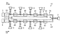
- the schematic diagram of the broadcast system which concerns on 1st Embodiment.
- FIG. 6 illustrates the operation of a branching isolator.
- the broadcast system 10 transmits a signal to the speaker 3 via the signal line 2.
- the broadcast system 10 is installed in a building and transmits audio information to the speakers 3 installed in each room.
- the audio information is not particularly limited.
- the voice information is contact information for notifying the public or a specific person, music sound information, disaster information, emergency evacuation information, and the like.
- the broadcast system 10 has a role of transmitting disaster information and emergency evacuation information when a disaster or the like occurs. If there is an abnormality in the broadcasting system 10 and the broadcastable area is limited, the role of the emergency notification can not be fully exerted. From such a thing, it is desirable for the broadcast system 10 to be provided with a function capable of suppressing a broadcast failure caused by an abnormality.
- the present technology is a technology relating to the suppression of broadcast failure.
- the broadcast failure indicates that it is not possible to transmit audio information to some or all of the speakers 3 based on a partial abnormality of the broadcast system 10.
- the broadcast system 10 according to the present embodiment will be described.
- the broadcast system 10 includes at least one broadcast output device 20 and a plurality of signal lines 2 connected to the broadcast output device 20.
- the plurality of signal lines 2 and an internal signal line 21 described later constitute one loop 1.
- the broadcast system 10 includes one or more isolators 40 attached to the signal line 2.
- the isolator 40 connects two signal lines 2 which are components of the loop 1.
- the speaker 3 is connected to the signal line 2 via the DC blocking filter 4.
- the direct current cut filter 4 is composed of, for example, a capacitor.
- the signal line 2 includes a pair of wires. Specifically, the signal line 2 includes the first wiring 2a and the second wiring 2b. The first wiring 2a is at a higher potential than the second wiring 2b, and the second wiring 2b is at a lower potential than the first wiring 2a. The first wiring 2a and the second wiring 2b are insulated from the ground.
- the broadcast output device 20 outputs output signals to the loop 1 in two directions.
- the broadcast output device 20 has a signal line (hereinafter, “internal signal line 21”) that constitutes a part of the loop 1.
- internal signal line 21 a portion other than the internal signal line 21 in the broadcast output device 20 is referred to as a loop main portion 1m.
- the broadcast output device 20 includes two terminals (hereinafter, “first terminal 31” and “second terminal 32”) connected to the signal line 2 of the loop body 1 m. The first terminal 31 and the second terminal 32 are connected by the internal signal line 21 in the broadcast output device 20.
- the broadcast output device 20 includes a power supply circuit 23, a ground fault detection unit 24, and a control unit 25.
- the power supply circuit 23 and the control unit 25 can be configured as an external device externally attached to the broadcast output device 20.
- the ground fault detection unit 24 may be omitted.
- the power supply circuit 23 generates a DC voltage of a first potential and a DC voltage of a second potential lower than the first potential based on the external power supply 5.
- the DC voltage of the first potential is input to the first wiring 21 a of the internal signal line 21.
- the DC voltage of the second potential is input to the second wiring 21 b of the internal signal line 21.
- the internal signal line 21 and the power supply circuit 23 are connected via an AC blocking filter 26 that blocks AC components.
- the AC blocking filter 26 prevents the AC component of the output signal (see below) transmitted to the internal signal line 21 from entering the power supply circuit 23 and suppresses the abnormal operation of the power supply circuit 23.
- the control unit 25 controls a loop connection switch 28 (see below) and a display unit (not shown).
- the control unit 25 outputs a display instruction signal to the display unit based on receiving various signals (first to third abnormality notification signals shown below).
- the display unit operates in a predetermined display mode (for example, lighting of a plurality of lamps) in accordance with a display instruction signal of the control unit 25.
- the manager of the broadcast system 10 can grasp the abnormality of the broadcast system 10 by the display mode of the display unit.
- the ground fault detection unit 24 detects that there is a short circuit between the first wiring 21 a and the ground and that there is a short circuit between the second wiring 21 b and the ground. When the ground fault detection unit 24 detects at least one of these short circuits, the ground fault detection unit 24 outputs a first abnormality notification signal indicating occurrence of a ground fault to the control unit 25.
- An input device 6 is connected to the broadcast output device 20.
- the input device 6 inputs a predetermined input signal to the broadcast output device 20.
- the input signal includes an audio signal corresponding to the above-mentioned audio information and a mechanical signal such as a tone signal.
- the pilot alternating signal described later is an example of a mechanical signal.
- the pilot alternating signal has a frequency outside the audible range or near the limit of the audible range.
- the pilot AC signal is configured as, for example, a 40 kHz or 20 kHz signal.
- the input signal is input to the internal signal line 21 through the noise cut filter 27.
- the input signal includes a first input signal transmitted to the first wiring 21 a and a second input signal transmitted to the second wiring 21 b.
- the first input signal includes an alternating current component
- the second input signal does not include an alternating current component.
- the input signal and the DC voltage are superimposed. That is, in the internal signal line 21, the first input signal and the direct current voltage of the first potential are superimposed, and the second input signal and the direct current voltage of the second potential are superimposed to form an output signal.
- the output signal is transmitted through the internal signal line 21 in two directions, a first direction D1 and a second direction D2 opposite to the first direction D1.
- An output signal in the first direction D1 is output from the first terminal 31, and an output signal in the second direction D2 is output from the second terminal 32.
- the broadcast output device 20 further includes a first switch 33, a second switch 36, a first short circuit detector 34, and a second short circuit detector 37. Furthermore, the broadcast output device 20 includes a loop connection switch 28. The first switch 33, the second switch 36, and the loop connection switch 28 are provided on the internal signal line 21.
- a loop connection switch 28 is provided between the first terminal 31 and the second terminal 32 in the internal signal line 21.
- the loop connection switch 28 connects “on” to connect the first terminal 31 and the second terminal 32 in the internal signal line 21 and disconnects between the first terminal 31 and the second terminal 32 (signal transmission is And "off" to be in a shut-off state.
- the loop connection switch 28 closes and opens the loop 1 by switching on and off.
- the loop connection switch 28 connects the switch 28 a that connects or disconnects the first wires 21 a and 21 a of the internal signal line 21 and the second wire 21 b and 21 b of the internal signal line 21.
- a switch 28b for disconnecting see FIG. 2.
- An open detection unit 29 is provided between the first terminal 31 and the loop connection switch 28 in the internal signal line 21.
- the open detection unit 29 detects whether or not the loop 1 is open.
- the release detection unit 29 operates at a predetermined step of “release detection processing” described later performed by the control unit 25 and detects release of the loop 1.
- "Open” indicates a state in which at least one of the first wiring 2a and the second wiring 2b of the signal line 2 constituting the loop 1 is cut. Hereinafter, this opening is called “loop opening”.
- the open detection unit 29 detects the potential difference between both ends of the resistor RD connected between the first wiring 2a and the second wiring 2b to determine whether the loop is open or not.
- a signal indicating that the loop is open hereinafter, referred to as “third error notification signal” is output to the control unit 25.
- the internal signal line 21 is provided with a first switch 33 and a second switch 36.
- the second switch 36 is disposed between the first switch 33 and the second terminal 32. That is, the first switch 33 is disposed closer to the first terminal 31 than the second switch 36.
- the second switch 36 is disposed closer to the second terminal 32 than the first switch 33.
- the first switch 33 and the second switch 36 are connected by an intermediate wiring 22 which is a component of the internal signal line 21.
- the loop connection switch 28 and the opening detection unit 29 described above are disposed between the first switch 33 and the first terminal 31.
- the first switch 33 connects between the first terminal 31 and the second switch 36 in the internal signal line 21 or disconnects between the first terminal 31 and the second switch 36. Specifically, in the first wiring 21 a of the internal signal line 21, the first switch 33 connects “on” the wiring on the first terminal 31 side and the intermediate wiring 22, and the wiring on the first terminal 31 side. It has an “off” for disconnecting from the intermediate wiring 22.
- the first switch 33 is turned “off” based on the detection of a short circuit by a first short circuit detector 34 described later.
- the first switch 33 turns “on” based on the fact that a first short detection unit 34 described later does not detect a short.
- the first short circuit detection unit 34 detects whether or not there is a short circuit in the signal line 2 on the first direction D1 side of the first switch 33.
- the short circuit indicates that the first wiring 2 a and the second wiring 2 b of the signal line 2 are in conduction.
- the first short circuit detection unit 34 includes a resistor RA connected to the first wiring 21 a in parallel with the first switch 33 and a first switch control unit 35.
- the potential of the first wiring 21a (potential on the first terminal 31 side) between the first switch 33 and the first terminal 31 is within a prescribed range (for example, the second potential (V) or more It is determined whether or not the range is equal to or less than a predetermined potential X lower than the first potential.
- the specified range indicates the potential range in the state in which the signal line 2 is shorted.
- the first switch control unit 35 determines that the short circuit has occurred. Then, the first switch control unit 35 turns off the first switch 33 and outputs a second abnormality notification signal to the control unit 25 when the detected potential is within the specified range (that is, there is a short circuit).
- the first switch control unit 35 turns on the first switch 33 when the detected potential is out of the specified range (that is, there is no short circuit).
- the second switch 36 has a structure similar to the first switch 33. Specifically, the second switch 36 is turned “off” on the internal signal line 21 based on the detection of a short circuit by the second short circuit detector 37 described later, and the second terminal 32 and the first switch 33 Between the second terminal 32 and the first switch 33 based on the fact that the second short circuit detection unit 37 does not detect a short circuit.
- the second short circuit detection unit 37 detects whether or not there is a short circuit in the signal line 2 on the second direction D2 side of the second switch 36.
- the second short circuit detection unit 37 includes a resistor RA connected to the first wire 21 a in parallel with the second switch 36 and a second switch control unit 38.
- the second switch control unit 38 determines whether the potential of the first wiring 21 a (potential on the second terminal 32 side) between the second switch 36 and the second terminal 32 is within a prescribed range.
- the specified range indicates the potential range in the state in which the signal line 2 is shorted.
- the second switch control unit 38 determines that a short circuit has occurred. Then, the second switch control unit 38 turns off the second switch 36 and outputs a second abnormality notification signal to the control unit 25 when the detected potential is within the prescribed range (that is, there is a short circuit).
- the second switch control unit 38 turns on the second switch 36 when the detected potential is out of the specified range (that is, there is no short circuit).
- both the first switch 33 and the second switch 36 are off, and the loop connection switch 28 is also off.
- the loop connection switch 28 is turned on.
- a DC voltage is input to the internal signal line 21 from the power supply circuit 23.
- a current flows in the resistor RA connected in parallel to the first switch 33.
- the signal line 2 on the first terminal 31 side is shorted to the first switch 33, the potential on the first terminal 31 side decreases, and the potential on the first terminal 31 side falls within the specified range.
- the first switch 33 is kept off by the first switch control unit 35.
- the second switch 36 operates in the same manner as the first switch 33.
- the signal line 2 on the side of the second terminal 32 is not short circuited, the potential on the side of the second terminal 32 is out of the specified range and the second switch 36 is turned on. It is transmitted to the signal line 2 on the two-direction D2 side.
- an input signal is input to the broadcast output device 20, an output signal is formed, so the output signal is output in the second direction D2.
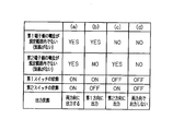
- the output form of the broadcast output device 20 will be described with reference to FIG. (A)
- the potential on the first terminal 31 side of the first switch 33 is not within the specified range (that is, there is no short circuit), and the potential on the second terminal 32 side of the second switch 36 is not within the specified range (that is, no short circuit is present) ),
- Output signals are outputted from two directions of the first direction D1 and the second direction D2.
- the isolator 40 connects the two signal lines 2 constituting the loop 1 as described above.
- the isolator 40 includes two terminals (hereinafter, “third terminal 42” and “fourth terminal 43”) to which the signal line 2 is connected.
- a signal line hereinafter, "internal signal line 41" connecting the third terminal 42 and the fourth terminal 43 in the isolator 40 is provided.
- the internal signal line 41 has a first wiring 41 a and a second wiring 41 b.
- the isolator 40 includes a separation switch 44, a third short circuit detector 45, and a fourth short circuit detector 47.
- the isolator 40 includes a power supply voltage generation circuit 49 that generates a power supply voltage.
- the separation switch 44 is provided on the first wiring 41 a of the internal signal line 41.
- the separation switch 44 connects the third terminal 42 and the fourth terminal 43 in the internal signal line 41 to “on” and disconnects the third terminal 42 and the fourth terminal 43 to “off”. Have.
- the separation switch 44 is turned “off” based on at least one of the third short circuit detector 45 and the fourth short circuit detector 47 detecting a short circuit.
- the separation switch 44 is turned “on” based on the fact that neither the third short detection unit 45 nor the fourth short detection unit 47 detects a short (see FIG. 5).
- the third short circuit detector 45 detects whether or not there is a short circuit in the part on the third terminal 42 side with respect to the separation switch 44.
- the third short circuit detection unit 45 includes a resistor RB connected to the first wiring 41 a in parallel with the separation switch 44 and a third switch control unit 46.
- the third switch control unit 46 determines whether or not the potential of the first wiring 41 a (potential on the third terminal 42 side) between the separation switch 44 and the third terminal 42 is within a specified range.
- the specified range indicates the potential range in the state in which the signal line 2 is shorted. When the potential on the third terminal 42 side with respect to the separation switch 44 is within the specified range, the third switch control unit 46 determines that a short circuit has occurred.
- the fourth short circuit detection unit 47 detects whether or not there is a short circuit in a portion on the fourth terminal 43 side with respect to the separation switch 44.
- the fourth short circuit detection unit 47 has the same structure as the third short circuit detection unit 45 except for the following point.
- the fourth short detection unit 47 includes a resistor RB connected to the first wiring 41 a in parallel with the separation switch 44, and a fourth switch control unit 48.
- the resistor RB is shared by the third short circuit detector 45 and the fourth short circuit detector 47.
- Power supply voltage forming circuit 49 generates a power supply voltage based on the output signal transmitted through signal line 2.
- the power supply voltage generated by the power supply voltage generation circuit 49 is supplied to the third short detection unit 45 and the fourth short detection unit 47 in the isolator 40.
- the power supply voltage formation circuit 49 has two input parts 49a and 49b. One input portion 49 a is connected to the first wiring 41 a between the separation switch 44 and the third terminal 42. The other input portion 49 b is connected to the first wiring 41 a between the separation switch 44 and the fourth terminal 43.
- the power supply voltage forming circuit 49 has the two input portions 49a and 49b, whereby the power supply voltage is formed regardless of the direction of transmission of the output signal.
- FIGS. 5A-5D illustrate the operation when an output signal is transmitted to the isolator 40 from at least one of two directions. At this time, since the power supply voltage is formed, the separation switch 44 operates.
- FIG. 5E shows the operation when the output signal is not transmitted to the isolator 40 from either of two directions. At this time, since the power supply voltage is not formed, the switch does not operate, and the separation switch 44 is kept off.
- the operation of the isolator 40 at startup of the broadcast system 10 will be described with reference to FIGS. 6 to 10.
- a case where there is a short circuit in the signal line 2 between the second isolator 40 and the third isolator 40 in the first direction D1 from the broadcast output device 20 will be described as an example.
- each switch of the broadcast output device 20 and the isolator 40 is "off".
- the loop connection switch 28 of the broadcast output device 20 is turned “on”.
- the first switch 33 and the second switch 36 of the broadcast output device 20 are "off”, and the separation switch 44 of the isolator 40 is "off".
- a DC voltage of a first potential is output to the first wiring 2 a of the signal line 2.
- the DC voltage is transmitted in the first direction D1 and the second direction D2.
- the potential on the third terminal 42 side of the separation switch 44 and the potential on the fourth terminal 43 side become values outside the prescribed range (values larger than the above-mentioned predetermined potential X larger than the second potential),
- the separation switch 44 is turned “on” by the operation of the third short circuit detection unit 45 and the fourth short circuit detection unit 47.
- the separation switch 44 of the second isolator 40 is maintained in the “off” state, whereby each isolator 40 on the first direction D1 side with respect to the second isolator 40 has the first direction D1.
- the DC voltage supplied from is not transmitted.
- a current flows in the short circuit portion SC of the loop 1 through at least one resistor RB, and a direct current voltage is not directly applied to the short circuit portion SC from the first direction D1.
- one of the potential on the third terminal 42 side and the potential on the fourth terminal 43 side of the separation switch 44 (potential near the short circuit portion SC) has a value within the prescribed range (value near the second potential) Become. Therefore, the third short circuit detection unit 45 or the fourth short circuit detection unit 47 determines that the short circuit has occurred, and the separation switch 44 is maintained in the "off" state.
- the separation switch 44 of the isolator 40 immediately before reaching the short circuit portion SC of the loop 1 in the second direction D2 is maintained in the “off” state.
- the direct current voltage supplied from the second direction D2 is not transmitted to each isolator 40.
- a current flows in the short circuit portion SC of the loop 1 via the at least one resistor RB, and direct voltage application to the short circuit portion SC from the second direction D2 is suppressed.
- each of the isolators 40 turns off the isolation switches 44 of the two isolators 40 sandwiching the short circuit portion SC of the loop 1.
- the short circuit portion SC of the loop 1 is substantially isolated from the range of the output signal transmission of the broadcast system 10. Then, the direct current voltage is not directly applied to the short circuit portion SC of the loop 1. In this manner, the flow of the overcurrent in the short circuit portion SC is suppressed.
- the broadcast output apparatus 20 and the isolator 40 perform short circuit detection as described above when power is supplied. Therefore, when the broadcast output device 20 and the isolator 40 detect a short circuit, the short circuit portion SC is isolated because the switch of the device that detects the short circuit is turned “off”. Thus, according to the broadcast system 10 of the present embodiment, a short circuit is always detected as long as power is supplied. And, when a short circuit is detected, the short circuit portion SC is automatically isolated.
- the isolator 40 detects a short circuit on both sides of the separation switch 44. Further, as described above, the broadcast output device 20 detects a short circuit on both sides of the first switch 33 and the second switch 36. By this configuration, each signal line 2 is sandwiched by two switches on the loop 1. Then, in each signal line 2, a short circuit is detected based on each of the output signals input from both directions (the first direction D1 and the second direction D2). When a short circuit occurs in the signal line 2, a short circuit is detected on both sides of the short circuit portion SC of the signal line 2, and switches on both sides of the signal line 2 are turned off. In this way, the signal line 2 including the short circuit portion SC is isolated from the loop 1.
- the second function of the isolator 40 will be described. Since the power supply voltage is not generated in the separation switch 44 of the isolator 40 before the start of the broadcast system 10, the third terminal 42 and the fourth terminal 43 are in a non-connected state. When the broadcast system 10 is activated, an output signal is output from the broadcast output device 20, and a power supply voltage is formed in the isolator 40 based on the output signal, and the separation switch 44 becomes operable. Further, the separation switch 44 connects between the third terminal 42 and the fourth terminal 43 based on the fact that the third short circuit detection unit 45 and the fourth short circuit detection unit 47 do not detect a short circuit.
- the isolator 40 is activated sequentially from the side closer to the broadcast output device 20 starting from the broadcast output device 20 at the time of startup, and a short circuit of the signal line 2 is detected sequentially from the side closer to the broadcast output device 20 Ru. If a short is detected, the signal line 2 with the short is isolated. In this manner, the flow of the overcurrent in the short circuit portion SC is suppressed at the time of start-up.
- the open detection process will be described with reference to FIGS. 11 and 12.
- the release detection process is a process for detecting whether or not the loop 1 is released.
- the release detection process is periodically executed by the control unit 25.
- the control unit 25 executes the release detection process at intervals of several tens of seconds.
- the control unit 25 executes the following steps S1 to S4 in the release detection process.
- step S1 the control unit 25 turns the loop connection switch 28 "off".
- the output signal is output only in the second direction D2.
- the output signal output from the second terminal 32 is input to the first terminal 31 via the loop 1.
- an output signal returned from the broadcast output device 20 and returned to the broadcast output device 20 is referred to as a "return signal”.
- the open detection unit 29 detects the presence or absence of the “return signal”.
- the open detection unit 29 does not detect the "return signal”.
- the release detection unit 29 outputs a signal indicating the presence or absence of the “return signal” to the control unit 25.
- step S ⁇ b> 2 the control unit 25 determines whether there is a “return signal” based on the detection result of the “return signal” of the open detection unit 29.
- the control unit 25 outputs a third abnormality notification signal indicating the loop open to the display unit in step S3.
- step S4 the loop connection switch 28 is turned “on” in step S4, and the release detection process is ended.
- step S2 when there is a "return signal” in step S2 (when the loop 1 is not opened)
- the control unit 25 turns on the loop connection switch 28 in step S4, and ends the opening detection process.
- the broadcast output device 20 outputs an output signal in the first direction D1 and the second direction D2 as described above. Therefore, when the loop 1 is open, an output signal is transmitted from the first direction D1 to one line LA between the broadcast output device 20 and the open portion OA in the loop 1 and the other line LB , And an output signal from the second direction D2. In this way, the output signal is transmitted to all the lines LA and LB.
- loop 1 has two opens, no output signal is transmitted between the two open parts OA, and an output signal is transmitted to the other part between the two open parts OA.
- the portion where the output signal is not transmitted can be reduced compared to a broadcast output device that outputs the output signal in only one direction.
- the broadcast output device 20 outputs an output signal in the first direction D1 and the second direction D2 of the loop 1. According to this configuration, since signals are transmitted from the broadcast output device 20 to the open portion OA from two directions, the range in which the signal is not transmitted in the loop 1 can be reduced when part of the loop 1 is open. . Also, according to the broadcast output device 20, no communication device is required to obtain this effect.
- the broadcast output device 20 outputs an output signal from one of the first direction D1 and the second direction D2 at a predetermined time (for example, periodically). Then, based on whether the “return signal” returned via the loop 1 is detected by the broadcast output device 20, it is determined whether the loop 1 has an abnormality. According to this configuration, it is possible to easily detect whether or not the loop 1 has an abnormality (in the present embodiment, it is open).
- the broadcast output device 20 forms an output signal to be output to the loop 1 by superimposing the input signal and the DC voltage.
- the isolator 40 operates based on the output signal to detect a short circuit of the signal line 2 connected to the isolator 40, and when there is no short circuit, connects the two signal lines 2 connected to the isolator 40, and the short circuit At one time, the two signal lines 2 connected to the isolator 40 are disconnected.
- the isolator 40 operates based on the power of the output signal to detect a short circuit. For this reason, the external power supply for operating the isolator 40 is unnecessary. Then, when there is a short circuit, the two signal lines 2 connected to the isolator 40 are disconnected. As a result, it can be prevented that the output signal continues to be transmitted to the wiring in which the short circuit occurs. In this way, when a short circuit occurs in the loop 1, the short circuit can be easily isolated.
- the first switch 33 of the broadcast output device 20 disconnects the first terminal 31 and the second switch 36 based on the detection of the short circuit by the first short circuit detector 34, and detects the first short circuit.
- the first terminal 31 and the second switch 36 are connected based on the fact that the unit 34 does not detect a short circuit.
- the second switch 36 of the broadcast output device 20 disconnects the second terminal 32 from the first switch 33 based on the second short circuit detection unit 37 detecting a short circuit, and the second short circuit detection unit 37
- the second terminal 32 and the first switch 33 are connected based on not detecting a short circuit. According to this configuration, when there is a short circuit in the signal line 2 connected to the broadcast output device 20, transmission of the output signal to the short circuit portion SC can be suppressed.
- the separation switch 44 of the isolator 40 detects a short between the third terminal 42 and the fourth terminal 43 based on at least one of the third short circuit detector 45 and the fourth short circuit detector 47 detecting a short circuit. Connect Further, the separation switch 44 connects the third terminal 42 and the fourth terminal 43 based on the fact that neither the third short detection unit 45 nor the fourth short detection unit 47 detects a short. According to this configuration, when there is a short circuit in the signal line 2 connected to the isolator 40, transmission of the output signal to the short circuit portion SC can be suppressed.
- the isolator 40 disconnects the third terminal 42 from the fourth terminal 43 when the output signal does not reach the isolator 40. According to this configuration, the separation switch 44 is “off” before the broadcast system 10 is activated. When the output signal is input to the isolator 40, the isolator 40 operates. With such a configuration, it is possible to suppress the flow of current to the short circuit portion SC when the broadcast system 10 is started.
- the broadcast system 11 according to the second embodiment will be described with reference to FIGS. 14 to 18.
- the broadcast system 11 according to the second embodiment includes one loop 1 and a branch signal line 7 branched from the loop 1.
- the signal line 2 and the branch signal line 7 constituting the loop 1 are connected via the branch isolator 50.
- the broadcast system 11 according to the second embodiment is different from that of the first embodiment in two points of having the branch signal line 7 and having the branch isolator 50.
- detection of an abnormality in the branch signal line 7 will be described.
- the same components as the components shown in the first embodiment will be assigned the same reference numerals as the symbols given to the components of the first embodiment.
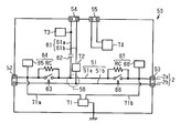
- FIG. 15 is a circuit diagram of the branching isolator 50.
- the branching isolator 50 connects the signal line 2 forming the loop 1 and the branching signal line 7.
- the branching isolator 50 has two terminals (hereinafter, “first loop terminal 52” and “second loop terminal 53”) to which the signal line 2 forming the loop 1 is connected, and a terminal to which the branch signal line 7 is connected. (Hereinafter, "branch terminal 54").
- a signal line hereinafter, “internal signal line 51” that connects the first loop terminal 52 and the second loop terminal 53 in the branch isolator 50 is provided.
- the internal signal line 51 has a first wiring 51a and a second wiring 51b.
- a signal line (hereinafter, “internal branching signal line 61”) connecting the branching terminal 54 and the internal signal line 51 is provided.
- the internal branch signal line 61 has a first wire 61a and a second wire 61b.
- a portion where the internal signal line 51 and the internal branch signal line 61 are connected is referred to as a “branch portion 56”.
- the branching isolator 50 includes a branching end terminal 55 to which the end of the branching signal line 7 is connected.
- the first wiring 61 a of the internal branch signal line 61 is provided with a DC blocking filter 62 for blocking a DC component.
- the DC blocking filter 62 blocks the DC component of the output signal and passes the AC component.
- the direct current cut filter 62 passes signals of a frequency including an audible range and a range before and after the audible range. That is, only alternating current is transmitted to the branch signal line 7. For this reason, the speaker 3 which does not have a DC blocking filter can be connected to the branch signal line 7.
- the branch isolator 50 includes a first separation switch 63, a second separation switch 66, a fifth short detection unit 64, and a sixth short detection unit 67.
- the branching isolator 50 includes a power supply voltage formation circuit 71.
- the branch isolator 50 is a branch short circuit detection unit 72 that detects the current of the branch signal line 7, a pilot AC detection unit 73 that detects a pilot AC signal described later, and a first wire 7 a of the branch signal line 7.
- a branch voltage detection unit 74 that detects a voltage difference between the second wiring 7b and the second wiring 7b.
- the first separation switch 63 and the second separation switch 66 are provided on the first wiring 51 a of the internal signal line 51.
- the first separation switch 63 is provided between the first loop terminal 52 and the branch portion 56.
- the second separation switch 66 is provided between the second loop terminal 53 and the branch portion 56. That is, the first separation switch 63 and the second separation switch 66 are disposed to sandwich the branch portion 56.
- the first separation switch 63 has “on” for connecting the first loop terminal 52 and the branch portion 56 and “off” for disconnecting the first loop terminal 52 from the branch portion 56.
- the second separation switch 66 has “on” for connecting the second loop terminal 53 and the branch 56 and “off” for disconnecting the second loop terminal 53 from the branch 56.
- the first separation switch 63 is turned “off” regardless of the detection state of the fifth short circuit detection unit 64 based on the detection of a short circuit by the branch short circuit detection unit 72 described later.
- the first separation switch 63 is turned “off” based on the branch short circuit detector 72 described later not detecting a short circuit and the fifth short circuit detector 64 described later detecting a short circuit.
- the first separation switch 63 is turned “on” based on the branch short circuit detector 72 described later not detecting a short circuit and the fifth short circuit detector 64 described later not detecting a short circuit.
- the second separation switch 66 is turned “off” regardless of the detection state of the sixth short circuit detection unit 67 based on the detection of a short circuit by the branch short circuit detection unit 72 described later.
- the second separation switch 66 is turned “off” based on the branch short circuit detection unit 72 described later not detecting a short circuit and the sixth short circuit detection unit 67 detecting a short circuit.
- the second separation switch 66 is turned “on” based on the fact that a branch short circuit detection unit 72 described later does not detect a short circuit and the sixth short circuit detection unit 67 does not detect a short circuit.
- the fifth short circuit detector 64 detects whether or not there is a short circuit in the portion on the first loop terminal 52 side with respect to the first separation switch 63.
- the fifth short circuit detector 64 includes a resistor RC connected to the first wire 51 a in parallel with the first separation switch 63 and a fifth switch controller 65.
- the fifth switch control unit 65 determines whether the potential of the first wiring 51a (potential on the first loop terminal 52 side) between the first separation switch 63 and the first loop terminal 52 is within a prescribed range. Do.
- the specified range indicates the potential range in the state in which the signal line 2 is shorted. When the potential on the first loop terminal 52 side is within the prescribed range, the fifth switch control unit 65 determines that a short circuit has occurred.
- the sixth short circuit detection unit 67 detects whether or not there is a short circuit in the portion on the second loop terminal 53 side with respect to the second separation switch 66.
- the sixth short circuit detector 67 includes a resistor RC connected in parallel to the second separation switch 66 to the first wire 51 a and a sixth switch controller 68.
- the sixth switch control unit 68 determines whether or not the potential of the first wiring 51a (potential on the second loop terminal 53 side) between the second separation switch 66 and the second loop terminal 53 is within a prescribed range. Do.
- the specified range indicates the potential range in the state in which the signal line 2 is shorted. When the potential on the second loop terminal 53 side is within the specified range, the sixth switch control unit 68 determines that a short circuit has occurred.
- the power supply voltage forming circuit 71 generally has the same structure as that shown in the first embodiment. Specifically, power supply voltage formation circuit 71 forms a power supply voltage based on the output signal transmitted through signal line 2.
- the power supply voltage generated by the power supply voltage forming circuit 71 is the fifth short circuit detector 64, the sixth short circuit detector 67, the branch short circuit detector 72, the pilot AC detector 73, and the branch voltage detector 74 in the branch isolator 50.
- Supplied to The power supply voltage forming circuit 71 has two inputs. One input portion 71 a is connected to the first wiring 51 a between the first separation switch 63 and the first loop terminal 52.
- the other input portion 71 b is connected to the first wiring 51 a between the second separation switch 66 and the second loop terminal 53.
- the power supply voltage forming circuit 71 has the two input parts 71a and 71b, so that the power supply voltage is formed by the power supply voltage forming circuit 71 regardless of the transmission direction of the output signal.
- the branch short circuit detection unit 72 detects the current of the internal branch signal line 61, and determines whether the current is within a specified range.
- the specified range indicates the current range when the branch signal line 7 is shorted.
- the branch short circuit detector 72 determines that a short circuit has occurred.
- both the first separation switch 63 and the second separation switch 66 are turned “off”.
- the pilot AC detection unit 73 detects a pilot AC signal. When the pilot AC detection unit 73 detects a pilot AC signal, the pilot AC detection unit 73 notifies the branch voltage detection unit 74 that the pilot AC signal has been detected.
- the branch voltage detection unit 74 detects the potential difference between the first wiring 7a and the second wiring 7b at the end of the branch signal line 7, and the potential difference is within the prescribed range. It is determined whether the The above-mentioned specified range indicates the voltage range when the branch signal line 7 is open. Then, the branch voltage detection unit 74 determines that the branch signal line 7 is open when the potential difference is within the specified range. When detecting the open state, the branch voltage detection unit 74 visibly displays a predetermined display (for example, lighting of a lamp) indicating that the open state is detected. Further, when detecting the open state, the branch voltage detection unit 74 turns “off” only one of the first separation switch 63 and the second separation switch 66.
- a predetermined display for example, lighting of a lamp
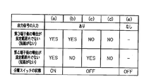
- FIGS. 16A to 16E show the case where the output signal is transmitted to the branching isolator 50 from at least one of the two directions.
- the switch since the power supply voltage is formed, the switch operates.
- (a) to (e) in FIG. 16 (a) to (d) are the first separation switch 63 and the second separation switch when the current of the branch signal line 7 is not within the specified range (that is, there is no short circuit).
- the operation of 66 is shown.
- FIG. 16F shows the case where the output signal is not transmitted to the branching isolator 50 from any of the two directions. At this time, since the power supply voltage is not formed, the switch does not operate and is kept off.
- (A) to (d) are states under the precondition that the current of the branch signal line 7 is not within the specified range (that is, there is no short circuit in the branch signal line 7).
- (A) In the above premise, when the potential on the first loop terminal 52 side of the first separation switch 63 is not within the specified range (that is, there is no short circuit), the first separation switch 63 is turned on. Further, under the above premise, when the potential on the second loop terminal 53 side of the second separation switch 66 is not within the specified range (that is, there is no short circuit), the second separation switch 66 is turned on. At this time, the two signal lines 2 connected to the branch isolator 50 are connected, and the two signal lines 2 and the branch signal line 7 are connected. Thus, the branch signal line 7 is connected to the loop 1 via the first loop terminal 52 and the second loop terminal 53 ("both connections").
- branching isolator 50 The operation of the branching isolator 50 at startup of the broadcast system 11 will be described with reference to FIGS. 17 and 18.
- a case where there is a short circuit in the signal line 2 on the first direction D1 side with respect to the branching isolator 50 will be described as an example.
- each switch of the broadcast output device 20, the isolator 40 and the branching isolator 50 is "off".
- the control unit 25 turns on the loop connection switch 28 of the broadcast output device 20.
- the control unit 25 outputs an output signal on which the pilot AC signal is superimposed from the broadcast output device 20.
- the pilot alternating signal is formed, for example, by the input device 6.
- the pilot AC signal is a signal used for open inspection of the branch signal line 7.
- the DC voltage is transmitted in the first direction D1 and the second direction D2. Then, for each of the isolators 40 that constitute the loop 1, a short circuit is sequentially detected in the first direction D1. When a short circuit is not detected by the isolator 40, the separation switch 44 of the isolator 40 is turned “on", and a DC voltage is transmitted to the adjacent isolator 40. Similarly, a short circuit is sequentially detected in the second direction D2 for each of the isolators 40 constituting the loop 1.
- the separation switch 44 of the isolator 40 immediately before the branch isolator 50 is turned “on” in the first direction D1
- a DC voltage is transmitted to the branch isolator 50.
- the power supply voltage forming circuit 71 of the branching isolator 50 operates to form a power supply voltage.
- the fifth short circuit detector 64, the sixth short circuit detector 67, the branch short circuit detector 72, the branch voltage detector 74, and the pilot alternating current detector 73 operate.
- the DC voltage is transmitted to the branching isolator 50, the DC voltage is applied to the branch signal line 7. Since the direct current cut filter 62 is provided in the internal branch signal line 61, only the AC component of the output signal is transmitted to the branch signal line 7.
- the pilot AC detection unit 73 detects a pilot AC signal. Based on this detection, the branch voltage detection unit 74 starts the detection of opening of the branch signal line 7.
- the branch voltage detection unit 74 detects the open state, for example, a display lamp provided in the branch isolator 50 is turned on. Thereby, the release is notified. Further, when the branch voltage detection unit 74 detects the open state, only one of the first separation switch 63 and the second separation switch 66 is turned “off”. Thus, the broadcast output device 20 can detect that the branch signal line 7 is open (see “open detection process” described later).
- the branch short circuit detector 72 starts detecting a short circuit in the branch signal line 7.
- the branch short circuit detection unit 72 detects a short circuit, as described above, the first separation switch 63 and the second separation switch 66 are both kept “off”.
- the switch command based on the "short circuit detection” by the branch short circuit detection unit 72 is a switch command based on the "short circuit detection” of the fifth short circuit detection unit 64 and the switch command based on the "short circuit detection” of the sixth short circuit detection unit 67.
- the sixth short circuit detection unit 67 determines that the short circuit has occurred and keeps the second separation switch 66 "off".
- the second separation switch 66 is maintained in the “off” state, so that the DC voltage supplied from the first direction D1 is applied to each isolator 40 on the first direction D1 side of the branch isolator 50. It will not be transmitted.
- a current flows in the short circuit portion SC of the loop 1 through at least two resistances RC and RC (see the broken line), and the direct current voltage is prevented from being applied to the short circuit portion SC directly from the first direction D1. Be done.
- the fifth short circuit detector 64 does not detect a short circuit, and turns the first separation switch 63 "on". Then, the branch signal line 7 is connected to the loop 1 through the first loop terminal 52. Thus, the alternating current of the output signal is transmitted to the branch signal line 7 (see FIG. 18).
- the operation of the switch group on the second direction D2 side in the loop 1 conforms to the operation of the switch group on the second direction D2 side in the loop 1 described in the first embodiment. Therefore, in this example, the separation switch 44 of the isolator 40 adjacent to the first direction D1 side with respect to the branching isolator 50 is kept off.
- the second separation switch 66 of the branch isolator 50 and the separation switch 44 of the isolator 40 sandwiching the short circuit portion SC of the loop 1 are turned “off”.
- the short circuit part SC of the loop 1 is substantially isolated from the range of the output signal transmission of the broadcast system 11.
- the direct current voltage is not directly applied to the short circuit portion SC of the loop 1. In this manner, the flow of the overcurrent in the short circuit portion SC is suppressed.
- each step of the release detection process is the same as that of the first embodiment.
- the operation of the open detection process will be described by taking the case where the branch signal line 7 is open as an example.
- the flowchart is the same as the flowchart shown in FIG.
- step S1 the control unit 25 turns the loop connection switch 28 "off". Thus, the output signal is output only in the second direction D2. Then, the output signal output from the second terminal 32 is input to the first terminal 31 via the loop 1.
- the branch signal line 7 When the branch signal line 7 is open, the "return signal” is not detected. This is because, as described above, when the branch signal line 7 is detected open, one of the first separation switch 63 and the second separation switch 66 is turned “off” in the branch isolator 50.
- step S ⁇ b> 2 the control unit 25 determines whether there is a “return signal” based on the detection result of the “return signal” of the open detection unit 29.
- the control unit 25 outputs a third abnormality notification signal indicating open loop to the display unit in step S3.
- the control unit 25 turns on the loop connection switch 28 in step S4, and ends the open detection process. As described above, it is detected that the branch signal line 7 is open by the same process as the open detection process shown in the first embodiment.
- the first separation switch 63 of the branching isolator 50 disconnects the first loop terminal 52 from the branching unit 56 based on the fifth short circuit detection unit 64 detecting a short circuit, and detects the fifth short circuit.
- the first loop terminal 52 and the branch portion 56 are connected based on the fact that the portion 64 does not detect a short circuit.
- the second separation switch 66 of the branching isolator 50 disconnects the second loop terminal 53 from the branching unit 56 based on the detection of the short circuit by the sixth short circuit detecting unit 67, and the sixth short circuit detecting unit 67
- the second loop terminal 53 and the branch portion 56 are connected based on the fact that the short circuit is not detected. According to this configuration, when there is a short circuit in the signal line 2 connected to the branching isolator 50, transmission of the output signal to the short circuit portion SC can be suppressed.
- the first separation switch 63 Based on the branch short circuit detection unit 72 of the branch isolator 50 detecting a short circuit of the branch signal line 7, the first separation switch 63 has the first loop terminal 52 and the branch portion 56 of the branch signal line 7.
- the second separation switch 66 disconnects the connection between the second loop terminal 53 and the branch portion 56 of the branch signal line 7. According to this configuration, when a short circuit is detected in branch signal line 7, branch signal line 7 is isolated from loop 1. This can suppress transmission of the output signal to the short circuit portion SC.
- the branching isolator 50 is provided with the DC blocking filter 62 disposed on the internal branching signal line 61 and blocking a DC component. According to this configuration, the branch signal line 7 can cut off the DC component. Thereby, the speaker 3 which is not provided with a capacitor for blocking a direct current component can be connected to the branch signal line 7.
- the broadcast output device 20 outputs a pilot AC signal for detecting the opening of the branch signal line 7.
- the branch isolator 50 detects the open of the branch signal line 7 when receiving the pilot AC signal. If any signal is not input to the branch signal line 7, the open of the branch signal line 7 can not be accurately detected. The reason for this is that there is no large difference between the potential difference when the signal is not inputted to the branch signal line 7 and the potential difference when the signal is open. In this respect, according to the above configuration, since the opening of the branch signal line 7 is detected when the pilot AC signal is received, it is possible to suppress the erroneous detection of the detection of the opening of the branch signal line 7.
- the branching isolator 50 further includes the power supply voltage generation circuit 71.
- the first separation switch 63 disconnects between the first loop terminal 52 and the branch portion 56 of the branch signal line 7 when the power supply voltage is not formed (the first separation switch 63 is “off”), and the second separation switch 63
- the separation switch 66 disconnects between the second loop terminal 53 and the branch portion 56 of the branch signal line 7 when the power supply voltage is not formed (the second separation switch 66 is “off”).
- both the first separation switch 63 and the second separation switch 66 are "off".
- the branch isolator 50 can detect a short circuit by inputting an output signal to the branch isolator 50. Thus, it is possible to suppress the flow of current to the short circuit portion SC when the broadcast system 11 is started.
- the broadcast output device 20 outputs an output signal from one of the first direction D1 and the second direction D2. Then, based on whether or not the return signal to be returned through the loop 1 is detected by the broadcast output device 20, it is determined whether or not there is an abnormality in the loop 1. According to this configuration, it can be detected whether or not there is an abnormality in the loop 1 (in the present embodiment, the open of the branch signal line 7).
- the configurations of the broadcast output device 20 and the broadcast systems 10 and 11 are not limited to the examples of the embodiment.
- the embodiments listed above can be modified as follows.
- the pilot AC signal is formed by the input device 6, but the pilot AC signal may be formed in the broadcast output device 20.
- line 2 is comprised by a pair of wiring, the structure of the signal wire
- the signal line 2 may be configured by one conductor. Also, the signal line 2 may be configured by a coaxial cable.
- D1 first direction
- D2 second direction
- LA line
- LB line
- OA open part
- RA resistance
- RB resistance
- RC resistance
- RD resistance
- SC shorted part
- 1 loop
- DESCRIPTION OF SYMBOLS 1m ... Loop main-body part 2 ... Signal line, 2a ... 1st wiring, 2b ... 2nd wiring, 3 ... Speaker, 4 ... DC blocking filter, 5 ... External power supply, 6 ... Input device, 7 ... Branch signal line, 7a ... 1st wiring, 7b ... 2nd wiring, 10 ... broadcast system, 11 ... broadcast system, 20 ... broadcast output device, 21 ... internal signal line, 21a ... 1st wiring, 21b ...
Landscapes
- Physics & Mathematics (AREA)
- Engineering & Computer Science (AREA)
- Acoustics & Sound (AREA)
- Signal Processing (AREA)
- Health & Medical Sciences (AREA)
- General Health & Medical Sciences (AREA)
- Otolaryngology (AREA)
- Computer Security & Cryptography (AREA)
- General Physics & Mathematics (AREA)
- Alarm Systems (AREA)
Abstract
L'invention concerne un système de diffusion (10) qui est pourvu d'une boucle (1) conçue pour transmettre un signal à un haut-parleur (3) et constituée d'une pluralité de lignes de signal (2), un ou plusieurs isolateurs (40) agencés entre les lignes de signal (2) constituant la boucle (1), et un dispositif de sortie de diffusion (20) pour délivrer en sortie un signal de sortie à la boucle (1). Le dispositif de sortie de diffusion (20) forme le signal de sortie délivré en sortie à la boucle (1) par superposition d'un signal d'entrée et d'une tension continue l'un sur l'autre. L'isolateur (40) fonctionne sur la base du signal de sortie, détecte un court-circuit de la ligne de signal (2) connectée à l'isolateur (40), connecte la pluralité de lignes de signal (2) connectées à l'isolateur (40) lorsqu'il n'y a pas de court-circuit, et laisse la pluralité de lignes de signal (2) connectées à l'isolateur (40) non connecté lorsqu'un court-circuit est détecté.
Priority Applications (2)
| Application Number | Priority Date | Filing Date | Title |
|---|---|---|---|
| EP17935278.6A EP3731539B1 (fr) | 2017-12-22 | 2017-12-22 | Système de diffusion |
| PCT/JP2017/046142 WO2019123636A1 (fr) | 2017-12-22 | 2017-12-22 | Système de diffusion |
Applications Claiming Priority (1)
| Application Number | Priority Date | Filing Date | Title |
|---|---|---|---|
| PCT/JP2017/046142 WO2019123636A1 (fr) | 2017-12-22 | 2017-12-22 | Système de diffusion |
Publications (1)
| Publication Number | Publication Date |
|---|---|
| WO2019123636A1 true WO2019123636A1 (fr) | 2019-06-27 |
Family
ID=66993303
Family Applications (1)
| Application Number | Title | Priority Date | Filing Date |
|---|---|---|---|
| PCT/JP2017/046142 Ceased WO2019123636A1 (fr) | 2017-12-22 | 2017-12-22 | Système de diffusion |
Country Status (2)
| Country | Link |
|---|---|
| EP (1) | EP3731539B1 (fr) |
| WO (1) | WO2019123636A1 (fr) |
Citations (3)
| Publication number | Priority date | Publication date | Assignee | Title |
|---|---|---|---|---|
| JPH0970099A (ja) * | 1995-08-30 | 1997-03-11 | Toa Corp | スピーカラインの検査装置 |
| JP2014509813A (ja) | 2011-03-25 | 2014-04-21 | アストレア インテレクチュイール ビー.ブイ. | 信号を通過させるためのアイソレーターデバイス |
| JP6033397B2 (ja) * | 2012-07-20 | 2016-11-30 | Toa株式会社 | 拡声システム及び拡声システムの監視装置 |
Family Cites Families (3)
| Publication number | Priority date | Publication date | Assignee | Title |
|---|---|---|---|---|
| GB2432091B (en) * | 2005-10-20 | 2009-06-17 | Protec Fire Detection Plc | Improvements to a public address system having zone isolator circuits |
| EP2017803B1 (fr) * | 2007-07-16 | 2011-07-06 | Herbert Puchner | Système de conservation des fonctions et de sécurisation actif pour réseaux de haut-parleurs d'alarmes dans une technique de conduite annulaire à deux fils |
| EP2862369B1 (fr) * | 2012-06-15 | 2016-05-25 | Toa Corporation | Système de sonorisation et dispositif de commande pour système de sonorisation |
-
2017
- 2017-12-22 EP EP17935278.6A patent/EP3731539B1/fr active Active
- 2017-12-22 WO PCT/JP2017/046142 patent/WO2019123636A1/fr not_active Ceased
Patent Citations (3)
| Publication number | Priority date | Publication date | Assignee | Title |
|---|---|---|---|---|
| JPH0970099A (ja) * | 1995-08-30 | 1997-03-11 | Toa Corp | スピーカラインの検査装置 |
| JP2014509813A (ja) | 2011-03-25 | 2014-04-21 | アストレア インテレクチュイール ビー.ブイ. | 信号を通過させるためのアイソレーターデバイス |
| JP6033397B2 (ja) * | 2012-07-20 | 2016-11-30 | Toa株式会社 | 拡声システム及び拡声システムの監視装置 |
Non-Patent Citations (1)
| Title |
|---|
| See also references of EP3731539A4 |
Also Published As
| Publication number | Publication date |
|---|---|
| EP3731539A4 (fr) | 2021-08-04 |
| EP3731539B1 (fr) | 2025-08-06 |
| EP3731539A1 (fr) | 2020-10-28 |
Similar Documents
| Publication | Publication Date | Title |
|---|---|---|
| KR101948753B1 (ko) | 스피커 선로 단락시 앰프 보호회로 | |
| KR101972136B1 (ko) | 스피커 선로 체크 기능을 이용한 안전한 비상 방송 장치 | |
| JP6262241B2 (ja) | 複数のdc電圧源を保護するためのシステム | |
| CN103299352B (zh) | 一种用于运行语音广播装置的方法 | |
| JP6033397B2 (ja) | 拡声システム及び拡声システムの監視装置 | |
| KR20200129975A (ko) | 선로 단락 단선 보호기능 통합관리 iot 전관방송시스템 | |
| WO2019123636A1 (fr) | Système de diffusion | |
| JP4493564B2 (ja) | スピーカライン検査装置及びスピーカライン検査装置用端末装置 | |
| CN106998055B (zh) | 电路切断系统 | |
| KR20070066900A (ko) | 안내 방송 시스템 및 이를 포함하는 선박 | |
| EP0967833B1 (fr) | Procédé d'utilisation d'un système d'annonce en public avec circuits isolateurs de zone | |
| JP6285696B2 (ja) | 中継器 | |
| JPH10241086A (ja) | 防災用監視システムにおける短絡検出方法及びこれを用いた防災用監視方法、防災用監視システム | |
| JP3640828B2 (ja) | 中継器及びそれを用いたネットワーク | |
| KR102164493B1 (ko) | 폴리스위치 내장형 스피커 장치 | |
| JP5908616B2 (ja) | 拡声システム及び拡声システムの制御装置 | |
| JP2019208310A (ja) | 回路遮断システム | |
| JP2022084786A (ja) | 伝送路断線位置検出装置及びブースター | |
| KR101362114B1 (ko) | 비상방송설비의 출력 제어장치 | |
| US9830291B2 (en) | Connecting device, method for the operation thereof, and bus communication device | |
| JP7499374B2 (ja) | 防災システム | |
| US8886044B2 (en) | Multi-channel fiber optic status monitoring device | |
| JP2025168926A (ja) | 開閉システム | |
| JP4334997B2 (ja) | 常開ループ配電の地絡保護方式 | |
| JP2025071716A (ja) | 統合システム |
Legal Events
| Date | Code | Title | Description |
|---|---|---|---|
| 121 | Ep: the epo has been informed by wipo that ep was designated in this application |
Ref document number: 17935278 Country of ref document: EP Kind code of ref document: A1 |
|
| NENP | Non-entry into the national phase |
Ref country code: DE |
|
| ENP | Entry into the national phase |
Ref document number: 2017935278 Country of ref document: EP Effective date: 20200722 |
|
| NENP | Non-entry into the national phase |
Ref country code: JP |
|
| WWG | Wipo information: grant in national office |
Ref document number: 2017935278 Country of ref document: EP |