WO2019123710A1 - 内視鏡用検査装置および内視鏡用検査システム - Google Patents
内視鏡用検査装置および内視鏡用検査システム Download PDFInfo
- Publication number
- WO2019123710A1 WO2019123710A1 PCT/JP2018/029832 JP2018029832W WO2019123710A1 WO 2019123710 A1 WO2019123710 A1 WO 2019123710A1 JP 2018029832 W JP2018029832 W JP 2018029832W WO 2019123710 A1 WO2019123710 A1 WO 2019123710A1
- Authority
- WO
- WIPO (PCT)
- Prior art keywords
- endoscope
- unit
- light
- signal
- inspection apparatus
- Prior art date
- Legal status (The legal status is an assumption and is not a legal conclusion. Google has not performed a legal analysis and makes no representation as to the accuracy of the status listed.)
- Ceased
Links
Images





Classifications
-
- H—ELECTRICITY
- H04—ELECTRIC COMMUNICATION TECHNIQUE
- H04N—PICTORIAL COMMUNICATION, e.g. TELEVISION
- H04N17/00—Diagnosis, testing or measuring for television systems or their details
- H04N17/002—Diagnosis, testing or measuring for television systems or their details for television cameras
-
- A—HUMAN NECESSITIES
- A61—MEDICAL OR VETERINARY SCIENCE; HYGIENE
- A61B—DIAGNOSIS; SURGERY; IDENTIFICATION
- A61B1/00—Instruments for performing medical examinations of the interior of cavities or tubes of the body by visual or photographical inspection, e.g. endoscopes; Illuminating arrangements therefor
- A61B1/00002—Operational features of endoscopes
- A61B1/00004—Operational features of endoscopes characterised by electronic signal processing
- A61B1/00009—Operational features of endoscopes characterised by electronic signal processing of image signals during a use of endoscope
-
- A—HUMAN NECESSITIES
- A61—MEDICAL OR VETERINARY SCIENCE; HYGIENE
- A61B—DIAGNOSIS; SURGERY; IDENTIFICATION
- A61B1/00—Instruments for performing medical examinations of the interior of cavities or tubes of the body by visual or photographical inspection, e.g. endoscopes; Illuminating arrangements therefor
- A61B1/00002—Operational features of endoscopes
- A61B1/00011—Operational features of endoscopes characterised by signal transmission
-
- A—HUMAN NECESSITIES
- A61—MEDICAL OR VETERINARY SCIENCE; HYGIENE
- A61B—DIAGNOSIS; SURGERY; IDENTIFICATION
- A61B1/00—Instruments for performing medical examinations of the interior of cavities or tubes of the body by visual or photographical inspection, e.g. endoscopes; Illuminating arrangements therefor
- A61B1/00002—Operational features of endoscopes
- A61B1/0002—Operational features of endoscopes provided with data storages
-
- A—HUMAN NECESSITIES
- A61—MEDICAL OR VETERINARY SCIENCE; HYGIENE
- A61B—DIAGNOSIS; SURGERY; IDENTIFICATION
- A61B1/00—Instruments for performing medical examinations of the interior of cavities or tubes of the body by visual or photographical inspection, e.g. endoscopes; Illuminating arrangements therefor
- A61B1/00002—Operational features of endoscopes
- A61B1/00059—Operational features of endoscopes provided with identification means for the endoscope
-
- A—HUMAN NECESSITIES
- A61—MEDICAL OR VETERINARY SCIENCE; HYGIENE
- A61B—DIAGNOSIS; SURGERY; IDENTIFICATION
- A61B1/00—Instruments for performing medical examinations of the interior of cavities or tubes of the body by visual or photographical inspection, e.g. endoscopes; Illuminating arrangements therefor
- A61B1/00142—Instruments for performing medical examinations of the interior of cavities or tubes of the body by visual or photographical inspection, e.g. endoscopes; Illuminating arrangements therefor with means for preventing contamination, e.g. by using a sanitary sheath
- A61B1/00144—Hygienic packaging
-
- A—HUMAN NECESSITIES
- A61—MEDICAL OR VETERINARY SCIENCE; HYGIENE
- A61B—DIAGNOSIS; SURGERY; IDENTIFICATION
- A61B1/00—Instruments for performing medical examinations of the interior of cavities or tubes of the body by visual or photographical inspection, e.g. endoscopes; Illuminating arrangements therefor
- A61B1/06—Instruments for performing medical examinations of the interior of cavities or tubes of the body by visual or photographical inspection, e.g. endoscopes; Illuminating arrangements therefor with illuminating arrangements
- A61B1/0661—Endoscope light sources
-
- G—PHYSICS
- G02—OPTICS
- G02B—OPTICAL ELEMENTS, SYSTEMS OR APPARATUS
- G02B23/00—Telescopes, e.g. binoculars; Periscopes; Instruments for viewing the inside of hollow bodies; Viewfinders; Optical aiming or sighting devices
- G02B23/24—Instruments or systems for viewing the inside of hollow bodies, e.g. fibrescopes
-
- H—ELECTRICITY
- H04—ELECTRIC COMMUNICATION TECHNIQUE
- H04N—PICTORIAL COMMUNICATION, e.g. TELEVISION
- H04N23/00—Cameras or camera modules comprising electronic image sensors; Control thereof
- H04N23/56—Cameras or camera modules comprising electronic image sensors; Control thereof provided with illuminating means
-
- H—ELECTRICITY
- H04—ELECTRIC COMMUNICATION TECHNIQUE
- H04N—PICTORIAL COMMUNICATION, e.g. TELEVISION
- H04N23/00—Cameras or camera modules comprising electronic image sensors; Control thereof
- H04N23/60—Control of cameras or camera modules
-
- H—ELECTRICITY
- H04—ELECTRIC COMMUNICATION TECHNIQUE
- H04N—PICTORIAL COMMUNICATION, e.g. TELEVISION
- H04N23/00—Cameras or camera modules comprising electronic image sensors; Control thereof
- H04N23/60—Control of cameras or camera modules
- H04N23/66—Remote control of cameras or camera parts, e.g. by remote control devices
-
- A—HUMAN NECESSITIES
- A61—MEDICAL OR VETERINARY SCIENCE; HYGIENE
- A61B—DIAGNOSIS; SURGERY; IDENTIFICATION
- A61B1/00—Instruments for performing medical examinations of the interior of cavities or tubes of the body by visual or photographical inspection, e.g. endoscopes; Illuminating arrangements therefor
- A61B1/00002—Operational features of endoscopes
- A61B1/00057—Operational features of endoscopes provided with means for testing or calibration
-
- H—ELECTRICITY
- H04—ELECTRIC COMMUNICATION TECHNIQUE
- H04N—PICTORIAL COMMUNICATION, e.g. TELEVISION
- H04N23/00—Cameras or camera modules comprising electronic image sensors; Control thereof
- H04N23/50—Constructional details
- H04N23/555—Constructional details for picking-up images in sites, inaccessible due to their dimensions or hazardous conditions, e.g. endoscopes or borescopes
Definitions
- the present invention relates to an endoscope inspection apparatus and an endoscope inspection system, and more particularly, an endoscope connected to an endoscope provided with an imaging unit and inspecting a failure state of the imaging unit in the endoscope. And an inspection system for an endoscope.
- An endoscope including an imaging element for imaging a subject inside a subject, an image processing apparatus called a so-called video processor that generates an observation image of the subject captured by the endoscope, and a subject from the endoscope 2.
- An endoscope system including a light source device and the like that generates and emits illumination light to be emitted to a light source is widely used in the medical field, the industrial field, and the like.
- the endoscope in such an endoscope system has a design and a structure considering a high degree of safety so that it can withstand many cases, which enables repeated use (reuse) over a long period of time It has become.
- so-called disposable endoscopes have also become known in recent years.
- This disposable type endoscope is basically premised to be used only for one case, and as a result, it often has a simple structure as compared with the reusable type endoscope.
- this type of endoscope regardless of the reuse type or disposable type, receives various treatment at a facility such as a hospital that is actually used after being shipped from a factory. Therefore, even if there is no defect at the time of factory shipment, there is a risk that the endoscope after shipment may be broken depending on the handling conditions.
- Japanese Patent Laid-Open Publication No. 2010-51440 discloses an endoscope system capable of determining the breakage state of the optical fiber constituting the light guide.
- JP-A-2010-51440 is a sensor which can be detachably attached to the distal end portion of the insertion portion of the endoscope, and receives the illumination light guided by the light guide.
- a breakage condition of the optical fiber is determined based on an output from the sensor using a light receiving unit provided with the sensor.
- the present invention has been made in view of the above circumstances, and it is an object of the present invention to provide an endoscope inspection apparatus and an endoscope inspection system capable of easily inspecting a failure state of an imaging unit in an endoscope. To aim.
- An endoscope inspection apparatus is an endoscope inspection apparatus connected to an endoscope including an imaging unit and inspecting a state related to a predetermined part of the endoscope, A communication unit capable of transmitting and receiving a predetermined signal to and from an endoscope, and a drive signal to be transmitted to the imaging unit via the communication unit in order to drive the imaging unit in the endoscope A response signal receiving unit that enables reception of a response signal from the imaging unit operated by the drive signal via the communication unit, and the response signal received by the response signal receiving unit.
- a first determination unit that determines whether the state of the imaging unit in the endoscope is good or bad, and a notification unit that reports predetermined information based on the determination result of the first determination unit. .
- the endoscope inspection apparatus is the endoscope inspection apparatus, wherein the communication unit is a communication connector configured to be able to transmit and receive a predetermined signal to and from the endoscope.
- a communication terminal that can be electrically connected to an endoscope communication terminal provided in an endoscope connector portion of the endoscope, the endoscope communication terminal and the apparatus
- the communication connector includes a communication connector configured to transmit and receive a predetermined signal to and from the endoscope through the communication terminal, and the signal generation unit transmits the signal through the device communication terminal and the endoscope communication terminal.
- the drive signal to be transmitted to the imaging unit is generated, and the response signal receiving unit is operated from the imaging unit operated by the drive signal via the endoscope communication terminal and the device communication terminal.
- the response signal can be received.
- An inspection system for an endoscope includes the inspection apparatus for an endoscope, and a package for wrapping at least a predetermined portion of the endoscope.
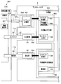
- FIG. 1 is a block diagram showing the electrical configuration of the endoscopy apparatus according to the first embodiment of the present invention.
- FIG. 2 is a block diagram showing an electrical connection between the endoscope inspection apparatus of the first embodiment and an endoscope to be inspected packaged in a blister pack.
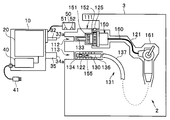
- FIG. 3 is a view showing a schematic configuration of an inspection device main body, an electrical connector portion, a light emitting portion and a light receiving portion in the endoscopic inspection device of the first embodiment.
- FIG. 4 is a view showing the endoscope inspection apparatus of the first embodiment and an endoscope to be inspected which is packaged in a blister pack.
- FIG. 5 is a view showing a state in which the endoscope inspection apparatus of the first embodiment and an endoscope to be inspected packaged in a blister pack are connected.
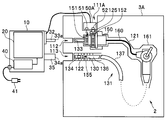
- FIG. 6 is a view showing a state in which the endoscope inspection apparatus of the first modified example of the present invention and the endoscope to be inspected packaged in a blister pack are connected.
- FIG. 7 is a block diagram showing the electrical configuration of the endoscopy apparatus according to the second embodiment of the present invention.
- FIG. 8 is a block diagram showing the electrical configuration of the endoscopy apparatus according to the third embodiment of the present invention.
- FIG. 9 is a block diagram showing an electrical connection between the endoscope inspection apparatus of the third embodiment and an endoscope to be inspected packaged in a blister pack.
- FIG. 1 is a block diagram showing the electrical configuration of the endoscopy apparatus according to the first embodiment of the present invention
- FIG. 2 is a diagram showing the endoscopy apparatus according to the first embodiment and a blister pack It is the block diagram which showed the electrical connection state with the endoscope which is the test object packaged.
- FIG. 3 is a view showing a schematic configuration of an inspection apparatus main body, an electrical connector, a light emitting part and a light receiving part in the endoscope inspection apparatus of the first embodiment
- FIG. 4 is a first embodiment. It is the figure which showed the endoscopic inspection apparatus of a form, and the endoscope which is the test object packaged in the blister pack.
- the endoscope 2 is an elongated insertion portion 131 which is inserted into a body cavity of a subject, and an endoscope operation portion 161 which is disposed on the proximal end side of the insertion portion 131 and which the operator grasps and operates.
- a universal cord 160 having one end provided so as to extend from the side of the endoscope operation unit 161, and a proximal end of the universal cord 160, which is not shown, of a light source device or a video processor
- an endoscope-side electrical connector portion 150 which is detachably connected to the front surface.
- the insertion portion 131 is provided at the rear end of the bending portion 136 and a bendable bending portion 136 provided at the rear end of the insertion portion front end portion 130 in addition to the hard insertion portion front end portion 130 provided on the front end side. It has a long and flexible flexible tube portion 137 and the like.
- the distal end portion 130 of the endoscope insertion portion has an objective optical system (not shown) including a lens for receiving an object image, and an image pickup disposed on an imaging surface in the objective optical system. And an imaging unit 155 including an element.
- the endoscope inspection apparatus relates to an inspection apparatus capable of easily inspecting a failure condition related to the “imaging unit” in the endoscope 2.
- a failure status related to an imaging unit includes “a failure status related to an imaging device”, a circuit portion that drives an imaging device, or even an imaging device. It shall include the fault condition concerning the circuit part including the electrical wiring.
- a light guide emission port 134 that constitutes an illumination unit that emits illumination light to a subject is formed on the distal end surface of the endoscope insertion portion distal end portion 130.
- An endoscope-side electrical connector 150 is disposed on the proximal end side of the universal cord 160.
- the endoscope side electrical connector unit 150 adopts a connector of a type in which a light guide and an electrical contact are integrated, and is detachably connected to the front of a light source device or a video processor (not shown) It is supposed to be
- the endoscope side electrical connector portion 150 adopts a connector of a type in which the light guide and the electrical contact are integrally formed, but the endoscope
- the configuration of the side electrical connector portion 150 is not limited to this, and another type of connector such as a connector type in which a so-called light guide connector and a video connector bifurcate may be adopted.
- the endoscope-side electrical connector unit 150 in the present embodiment includes a base (not shown) serving as a connection end of a fluid channel projecting from the tip of the endoscope-side electrical connector unit 150, and illumination light And a light guide inlet port 133, which is a light guide base, serving as the supply end of the light source.
- the wireless power receiving unit 151 and the endoscope side communication connector 152 are formed.
- the power supply means for the predetermined signal may be of another type, and for example, even if the power supply means and the communication means for the predetermined signal are constituted by one type of connector mechanism in common. Good.
- the wireless power receiving unit 151 has a power supply port for operating the endoscope 2 in cooperation with a wireless power transmission unit disposed in a video processor or the like when the endoscope 2 is connected to a video processor or the like. Become.
- the wireless power reception unit 151 serves as a supply port that receives power supply from the inspection apparatus main body 10 side.
- the predetermined power supply voltage supplied from the wireless power receiving unit 151 is also supplied to the imaging unit 155 through a known power supply line.
- the endoscope side communication connector 152 serves as communication means for transmitting and receiving a predetermined signal to the endoscope 2.
- the endoscope side communication connector 152 serves as a receiving unit for receiving a predetermined signal from the inspection apparatus main body 10 side when the endoscope 2 is inspected, and a state according to the imaging unit 155 Function as a transmitter of a response signal indicating.
- FIG. 1 is a block diagram showing the electrical configuration of the endoscopy apparatus according to the first embodiment of the present invention
- FIG. 2 is a diagram showing the endoscopy apparatus according to the first embodiment and a blister pack It is the block diagram which showed the electrical connection state with the endoscope which is the test object packaged.
- FIG. 3 is a view showing a schematic configuration of an inspection device main body, an electrical connector portion, a light emitting portion and a light receiving portion in the endoscopic inspection device of the first embodiment.
- the endoscope inspection apparatus includes an inspection apparatus main body 10, an apparatus-side electrical connector 50 extended from the inspection apparatus main body 10, and an electric cable 53.
- an AC plug 41 for supplying power to the inspection apparatus main body 10 and the like are included.
- the power supply supplied to the inspection apparatus main body 10 is a commercial power supply via the AC plug 41 or the like.
- the present invention is not limited thereto. May be mounted to receive a predetermined power supply from the battery.
- the inspection apparatus main body 10 includes a substrate unit 20 on which various circuit units related to endoscopic inspection are disposed, a power supply generating power to be supplied to the circuits in the substrate unit 20 and the endoscope 2 to be inspected. And a unit 40.
- the inspection apparatus main body 10 includes a power supply unit 40 for supplying power to each circuit in the substrate unit 20 and the imaging unit 155 and the like in the endoscope 2 to be inspected.
- An AC power cord 42 is connected to the power supply unit 40, and an AC plug 41 is disposed at the tip of the AC power cord 42 so as to receive supply of primary power from a commercial power supply.
- the AC power cord 42 is configured to be detachable by the connection connectors 42 a and 42 b disposed in the inspection apparatus main body 10.
- the power supply unit 40 supplies a predetermined DC power supply voltage supplied to each circuit in the substrate unit 20 and a predetermined DC power supply voltage supplied to the imaging unit 155 and the like in the endoscope 2 to be inspected. Generate and output to each circuit.
- the direct current power output toward the endoscope 2 is connected to a power supply line 53 b in an electric cable 53 described later via the inside of the substrate unit 20.
- the substrate unit 20 constitutes functional units having respective functions, that is, a transmitting / receiving unit 21 capable of transmitting / receiving a predetermined signal to / from the endoscope 2 to be inspected; A state of the signal generation unit 22 that generates a drive signal to be transmitted to the mirror 2, a response signal reception unit 23 that can receive a response signal from the endoscope 2, and a state related to the imaging unit 155 in the endoscope 2 Mainly a first determination unit 24 that determines whether the device is good or bad, a storage unit 25 that stores information related to the drive signal, and a notification unit 26 that notifies predetermined information based on the determination result of the first determination unit 24 Prepare.
- a transmitting / receiving unit 21 capable of transmitting / receiving a predetermined signal to / from the endoscope 2 to be inspected
- a state of the signal generation unit 22 that generates a drive signal to be transmitted to the mirror 2
- a response signal reception unit 23 that can receive a response signal from the endoscope 2
- Each functional unit such as the first determination unit 24 mainly performs an inspection of the imaging unit 155 in the endoscope 2 which is an inspection target.
- the substrate unit 20 also includes a light source unit 31 for generating inspection light to be supplied to the endoscope 2, an optical fiber 32 for transmitting the inspection light, and a conductor for transmitting the inspection light sent from the endoscope 2.
- a light source unit 31 for generating inspection light to be supplied to the endoscope 2
- an optical fiber 32 for transmitting the inspection light
- a conductor for transmitting the inspection light sent from the endoscope 2.
- the functional units such as the second determination unit 37 mainly perform inspection of the illumination optical system in the endoscope 2 to be inspected.
- the substrate unit 20 further includes a control unit 27 for controlling the above-described respective functional units (portions indicated by reference numeral 20a in FIG. 1).
- Control unit 27 controls the operation of each circuit in each functional unit 20a according to an operation not shown.
- the substrate unit 20 serves as an imaging unit inspection function unit that inspects the imaging unit 155 in the endoscope 2 to be inspected, and the transmission / reception unit 21, the signal generation unit 22, the response signal reception unit 23, the first A determination unit 24, a storage unit 25, and a notification unit 26 are provided.
- the storage unit 25 stores information related to the drive signal according to the type of endoscope to be inspected.
- the drive signal is a signal for driving the imaging unit 155 in the endoscope 2 when the endoscope 2 is connected to the inspection apparatus main body 10 in a state in which the endoscope 2 is included in the blister pack 3.
- the storage unit 25 further stores pattern information of a reference response signal corresponding to the type of endoscope (this point will be described later).
- the signal generation unit 22 is connected to the storage unit 25 and the transmission / reception unit 21, and is an inspection target connected to the inspection apparatus main body 10 based on the information stored in the storage unit 25 under the control of the control unit 27.
- a drive signal corresponding to the type of the endoscope 2 is generated and output toward the transmission / reception unit 21 in the subsequent stage.
- the drive signal generated by the signal generation unit 22 is transmitted to the endoscope 2 via the transmission / reception unit 21, the device communication connector 52, the endoscope communication connector 152 described later, and the like under the control of the control unit 27. It is intended to be sent towards.
- the transmission / reception unit 21 is connected to the signal generation unit 22 and the response signal reception unit 23, and transmits the drive signal generated by the signal generation unit 22 toward the endoscope 2 under the control of the control unit 27 and It has a function of receiving a response signal from the endoscope 2.
- the transmission / reception unit 21 configures a part of a communication unit that can transmit / receive a predetermined signal to / from the endoscope 2 to be examined.
- the predetermined signal is the drive signal and a response signal described later.
- the apparatus side communication connector 52 in the apparatus side electric connector part 50 mentioned later also comprises a part of said communication part.
- a communication line 53a is extended from the transmitting / receiving unit 21, and the other end of the communication line 53a is connected to a device communication connector 52 in a device electric connector 50 described later.
- an electric cable 53 is extended from the inspection apparatus main body 10, and the communication line 53a is installed in the electric cable 53 together with the power supply line 53b.
- the transmission / reception unit 21 receives the communication line 53 a under the control of the control unit 27.
- the drive signal generated in the signal generation unit 22 is transmitted to the endoscope 2 side via the side communication connector 52 and the endoscope side communication connector 152.
- the drive signal generated in the signal generation unit 22 is input to the endoscope 2 connected to the inspection apparatus main body 10 at the time of endoscopic examination, and the imaging unit 155 is driven. It becomes.
- the endoscope 2 outputs a response signal according to the operation of the imaging unit 155 driven by the drive signal.
- the response signal receiving unit 23 is under the control of the control unit 27 via the communication unit (endoscope side communication connector 152, device side communication connector 52, communication line 53a, transmitting / receiving unit 21 etc.) A response signal from the endoscope 2 can be received.
- the communication unit endoscope side communication connector 152, device side communication connector 52, communication line 53a, transmitting / receiving unit 21 etc.
- the response signal receiving unit 23 is the device-side communication connector 52 described above under the control of the control unit 27 at the time of examination of the endoscope 2, the response signal output from the endoscope 2;
- the signal is received via the communication line 53 a and the transmission / reception unit 21 and is output to the first determination unit 24 in the subsequent stage.
- the first determination unit 24 determines, based on the response signal received by the response signal receiving unit 23, whether the state of the imaging unit 155 in the endoscope is good or bad. For example, the first determination unit 24 may obtain “color chart information”, “white scratch information”, “noise information”, “image sensor itself” obtained from the response signal related to the image information acquired by the imaging unit 155 of the endoscope 2 It is determined whether the state of the imaging unit 155 is good or bad based on the “presence / absence information of failure”.
- the response signal is inspected with reference to the “pattern information of the reference response signal” stored in the storage unit 25.
- the notification unit 26 is in a state by predetermined warning information such as a warning sound, a warning message, blinking of the display unit, etc. Announce
- the electric cable 53 is extended from the inspection device main body 10 (see FIG. 1, FIG. 3 and the like). Further, as shown in FIG. 1 and the like, the electric cable 53 internally includes the communication line 53a and the power supply line 53b.
- One end of the communication line 53 a is connected to the transmission / reception unit 21, and the other end is connected to the device communication connector 52 in the device electric connector 50. Further, one end of the power supply line 53 b is connected to the output unit of the power supply unit 40 via the substrate unit 20, and the other end is connected to the power supply connector 51 in the device-side electrical connector unit 50.
- the device-side electrical connector unit 50 is disposed at the tip of the electrical cable 53 extended from the inspection device main body 10 and is a blister that wraps the endoscope 2 to be inspected. It has a shape fitted to the first joint portion 111 in the pack 3 (details will be described later) (the first joint portion 111 will be described in detail later).
- the device-side electrical connector unit 50 is internally provided with a wireless power transmission unit 51 for supplying power to the endoscope 2 and a device-side communication connector 52 for transmitting / receiving a predetermined signal to / from the endoscope 2.
- the wireless power transmission unit 51 includes a wireless power transmission coil and a coil drive unit.
- the coil drive unit converts a DC power supply voltage output from the power supply unit 40 via the power supply line 53b provided in the electric cable 53 into a predetermined alternating voltage and applies the voltage to the wireless power transmission coil,
- the power transmission coil is thereby configured to transmit predetermined power source energy.
- the wireless power transmission unit 51 when the wireless power transmission unit 51 is disposed when the device-side electrical connector unit 50 is fitted to the first joint unit 111 in the blister pack 3 at the time of the imaging unit inspection of the endoscope 2, the wireless power reception unit 151 is , And supplies predetermined electric energy to the wireless power receiver 151 by known electromagnetic induction.
- the device-side communication connector 52 includes device-side communication connector terminals 52 a and 52 b connected to a communication line 53 a provided in the electric cable 53.
- the device-side communication connector terminals 52a and 52b are formed with the terminal portions exposed.
- the device side communication connector terminals 52a and 52b are disposed in the blister pack 3 when the device side electrical connector portion 50 is fitted to the first mating portion 111 of the blister pack 3 at the time of the imaging portion inspection of the endoscope 2 Electrically connected to the endoscope side communication connector terminals 152a and 152b disposed on the endoscope side communication connector 152 through the exposed conductive portions 125 (see FIG. 4 and FIG. 5 etc.) formed in 3 It is supposed to be
- the blister pack 3 is exposed so as to conduct electricity while maintaining the clean state of the endoscope 2 which contains the endoscope side communication connector terminals 152 a and 152 b and the outside of the blister pack 3.
- Conduction portion 125 (see FIG. 4 and the like) is formed.
- the exposed conductive portion 125 is the device-side communication connector in the device-side electrical connector portion 50. Electrical connections are also made to 52. Thereby, the apparatus side communication connector terminals 52a, 52b and the endoscope side communication connector terminals 152a, 152b are electrically connected.
- the substrate unit 20 is a light source unit 31, an optical fiber 32, a light guide path 35, an optical sensor as a functional unit that inspects the illumination optical system etc. in the endoscope 2 to be inspected in addition to the imaging unit inspection function unit described above.
- the notification unit 26 and the like are provided.
- the light emitting unit 33, the light receiving unit 34, and the like will be described.
- the light source unit 31 generates inspection light for inspecting the illumination optical system in the endoscope 2.
- the inspection light is set to a light sufficient for inspecting the endoscope 2 in the present embodiment.
- the optical fiber 32 is connected to the output end of the light source unit 31 and extends from the inspection apparatus main body 10 and transmits the inspection light generated in the light source unit 31.
- a light emitting unit 33 is disposed at the tip of the optical fiber 32.
- the light emitting portion 33 is provided at the tip of the optical fiber 32 extended from the inspection device main body 10, and has a shape fitted to the second bonding portion 112 in the blister pack 3 (about the second bonding portion 112 Will be described in detail later).
- the said blister pack 3 fulfill
- a light emission port 33 a is formed on the tip end surface of the light emission unit 33, and the inspection light transmitted from the light source unit 31 via the optical fiber 32 is contained in the blister pack 3 in the endoscope 2. It emits light to the light guide entrance port 133.
- the light receiving portion 34 is provided at the tip of the light guide 35 extended from the inspection apparatus main body 10, and has a shape to be fitted to the third coupling portion 113 in the blister pack 3 (about the third coupling portion 113 Will be described in detail later).
- a light receiving surface 34 a is formed on the tip end surface of the light receiving unit 34 so as to receive inspection response light emitted from the light guide outlet 134 in the endoscope 2 contained in the blister pack 3. There is.
- the light guide path 35 is disposed so as to extend from the inspection apparatus main body 10, the light receiving unit 34 is formed at one end, and the other end is connected to the light sensor unit 36.
- the light guide 35 transmits the inspection response light from the endoscope 2 received by the light receiving surface 34 a of the light receiving unit 34 to the light sensor unit 36.
- the light sensor unit 36 in the illumination optical system inspection function unit on the substrate unit 20 receives the inspection response light from the endoscope 2 transmitted through the light guide 35 and converts the light into a predetermined electric signal. Output.
- the second determination unit 37 receives the electrical signal from the light sensor unit 36, and based on the electrical signal, the condition regarding the illumination optical system such as a light guide in the endoscope 2 to be inspected is good or bad To judge.
- the notification unit 26 has a function of notifying predetermined information based on the determination result of the first determination unit 24 and notifying of predetermined information based on the determination result of the second determination unit 37.
- the endoscope inspection apparatus determines the inspection of the endoscope 2, particularly whether the state of the imaging unit is good or bad, but the inspection of the endoscope 2 is a so-called blister It is characterized in that it is inspected in the state of being packaged in the pack 3.
- the blister pack 3 for packaging the endoscope 2 applied in the endoscope inspection apparatus of the present embodiment is, as shown in FIGS. 2 and 4, a predetermined portion of the endoscope 2, for example, an endoscope-side electrical connector It is a package which wraps the part 150, the universal cord 160, the endoscope operation part 161, the endoscope insertion part 131 (the endoscope insertion part tip part 130, the bending part 136, the flexible tube part 137) and the like.
- the blister pack 3 applied in the present embodiment is a so-called package dedicated to the endoscope 2 in which a packaging portion corresponding to the size and shape of each predetermined portion in the predetermined endoscope 2 is formed. .
- the blister pack 3 includes a first fixing portion 121 for accurately fixing the endoscope-side electrical connector portion 150 in the packaged endoscope 2, and the endoscope insertion.
- a second fixing portion 122 for fixing the distal end portion 130 and the bending portion 136 is formed.
- the wireless power reception unit 151 in the endoscope-side electrical connector unit 150 fixed by the first fixing unit 121 and the wireless power transmission unit 51 in the device-side electrical connector unit 50 reliably.
- the endoscope side communication connector terminals 152a and 152b in the endoscope side electric connector portion 150 and the device side communication connector terminals 52a and 52b in the device side electric connector portion 50 so as to be disposed at the opposite positions.
- the first fitting portion 111 is provided for fitting the device-side electrical connector portion 50 so as to be electrically connected reliably through the exposed conductive portion 125.
- the inspection light emitted from the light emitting unit 33 is incident on the light guide incident port 133 in the endoscope-side electrical connector unit 150 fixed by the first fixing unit 121.
- a second fitting portion 112 for fitting the light emitting portion 33 is provided.
- the blister pack 3 receives the inspection response light emitted from the light guide outlet 134 at the distal end portion 130 of the endoscope insertion portion fixed by the second fixing portion 122 at the light receiving portion 34 of the light receiving portion 34.
- a third fitting portion 113 is provided for fitting the light receiving portion 34 so that light can be reliably received at 34 a.
- FIG. 2 is a block diagram showing an electrical connection between the endoscope inspection apparatus of the first embodiment and an endoscope to be inspected packaged in a blister pack.
- FIG. 4 is a view showing the endoscope inspection apparatus of the first embodiment and an endoscope to be inspected packaged in a blister pack, and
- FIG. 5 is a diagram showing the first embodiment.
- FIG. 12 is a diagram showing a state in which the endoscope inspection apparatus of the present invention and the endoscope to be inspected packaged in a blister pack are connected.
- any of the apparatus side electrical connector sections extended from the inspection apparatus main body 10 50, an optical fiber 32 (a light emitting portion 33, a light emitting port 33a) and a light guide 35 (a light receiving portion 34, a light receiving surface 34a) are formed on the blister pack 3 respectively.
- the joint portion 112 and the third joint portion 113 are connected so as to be fitted.
- the wireless power transmission unit 51 and the device-side communication connector 52 disposed therein are each an endoscope-side electrical connector
- the wireless power receiver 151 in the unit 150 approaches the endoscope side communication connector 152.
- the wireless power transmission unit 51 in proximity to the wireless power reception unit 151 converts the DC power supply voltage sent from the power supply unit 40 via the power supply line 53b into a predetermined alternating voltage in the inscribed coil drive unit and converts it into a wireless power transmission coil. Apply.
- the wireless power transmission coil transmits predetermined power source energy toward the wireless power reception unit 151.
- the wireless power transmission unit 51 is disposed when the device-side electrical connector unit 50 is fitted to the first joint unit 111 in the blister pack 3 at the time of the imaging unit inspection of the endoscope 2, the wireless power reception unit 151 is Are disposed opposite to each other, and supply predetermined electric energy to the wireless power reception unit 151 by known electromagnetic induction.
- the device communication connector 52 the device communication connectors 52a and 52b connected to the communication wire 53a provided in the electric cable 53 are exposed conductive portions 125 formed in the blister pack 3 (FIG. 4, FIG.
- the endoscope side communication connector terminals 152a and 152b disposed in the endoscope side communication connector 152 are electrically connected to each other via the reference 5 and the like.
- the light emitting port 33 a is a light guide in the endoscope side electrical connector portion 150. It is arranged to face the entrance port 133.
- the light receiving portion 34 formed at the tip of the light guide path 35 is disposed such that the light receiving surface 34 a thereof faces the light guide outlet 134.
- the device-side electrical connector unit 50, the light emitting unit 33, and the light receiving unit 34 are engaged with the first joint portion 111, the second joint portion 112 and the third joint portion 113 in the blister pack 3, respectively. Then, power is supplied from the power supply unit 40 in the inspection apparatus main body 10 to each circuit in the substrate unit 20 by the operation unit (not shown), and the power supply line 53b in the electric cable 53, the wireless power transmission unit 51, and the wireless power reception unit 151 Power is supplied to each circuit including the imaging unit 155 in the endoscope 2 through the above.
- the signal generation unit 22 in the inspection apparatus main body 10 generates and outputs a drive signal according to the type of the endoscope 2 based on the information stored in the storage unit 25 under the control of the control unit 27. .
- the drive signal is output from the transmission / reception unit 21 and transmitted to the imaging unit 155 from the endoscope side communication connector 152 connected to the device communication connector 52 via the communication line 53 a.
- the endoscope 2 sends a response signal according to the operation of the imaging unit 155 driven by the drive signal toward the inspection apparatus main body 10 side.
- the response signal receiving unit 23 in the inspection apparatus body 10 controls the control unit via the communication unit (endoscope communication connector 152, device communication connector 52, communication line 53a, transmission / reception unit 21 etc.) Under control of 27, the response signal from the endoscope 2 is received.
- the communication unit endoscope communication connector 152, device communication connector 52, communication line 53a, transmission / reception unit 21 etc.
- the response signal receiving unit 23 outputs the response signal received via the transmitting / receiving unit 21 to the first determining unit 24 in the subsequent stage.
- the first determining unit 24 determines whether the state of the imaging unit 155 in the endoscope is good or bad under the control of the control unit 27. to decide. For example, the first determination unit 24 may obtain “color chart information”, “white scratch information”, “noise information”, “image sensor itself” obtained from the response signal related to the image information acquired by the imaging unit 155 of the endoscope 2 It is determined whether the state of the imaging unit 155 is good or bad based on the “presence / absence information of failure”.
- the response signal is inspected with reference to the “pattern information of the reference response signal” stored in the storage unit 25.
- the notification unit 26 is in a state by predetermined warning information such as a warning sound, a warning message, blinking of the display unit, etc. Announce
- the endoscope inspection apparatus of the first embodiment it is possible to easily inspect the failure status of the imaging unit in the endoscope.
- the endoscope inspection apparatus is the same as the first embodiment in the main configuration, and the shape of the first joint portion with which the apparatus-side electrical connector in the inspection apparatus main body 10 engages is different. It is characterized in that the blister pack 3A can also be handled. Therefore, only the difference from the first embodiment will be described here, and the description of the common parts will be omitted.
- FIG. 6 is a view showing a state in which the endoscope inspection apparatus of the first modified example of the present invention and the endoscope to be inspected packaged in a blister pack are connected.
- the blister pack 3A corresponding to the endoscopic inspection apparatus of the first modification is formed with the first joint portion 111A having a shape different from that of the first joint portion 111 in the blister pack 3 described above. Be done. That is, the first joint portion 111A is formed so that the device-side electrical connector portion 50A extended from the inspection device main body 10 can be inserted from the upper side in the drawing of FIG.
- FIG. 7 is a block diagram showing the electrical configuration of the endoscopy apparatus according to the second embodiment of the present invention.
- the endoscope inspection apparatus 201 of the second embodiment has a configuration specialized in the inspection unit of the imaging unit, omitting the illumination optical system inspection unit with respect to the inspection apparatus main body 10 of the first embodiment. It features. Therefore, only the difference from the first embodiment will be described here, and the description of the common parts will be omitted.
- the endoscope inspection apparatus includes an inspection apparatus main body 210, an apparatus-side electrical connector 50 extended from the inspection apparatus main body 210, an electric cable 53, and an inspection apparatus. It comprises an AC plug 41 or the like for supplying power to the main body 210.
- the endoscope inspection apparatus according to the second embodiment is the optical fiber 32, the light emitting unit 33, the light receiving unit 34, the light guide path 35, etc. provided in the endoscope inspection apparatus according to the first embodiment. Is omitted.
- the second embodiment is the same as the first embodiment as an imaging unit inspection function unit that inspects the imaging unit 155 in the endoscope 2 to be inspected in the substrate unit 220 in the inspection apparatus main body 210.
- the transmission / reception unit 21, the signal generation unit 22, the response signal reception unit 23, the first determination unit 24, the storage unit 25, and the notification unit 26 are provided, but the circuit unit related to the illumination optical system inspection unit is omitted.
- the endoscope inspection apparatus can not execute the inspection related to the illumination optical system in the endoscope 2 as compared with the first embodiment, but the inspection related to the imaging unit in the endoscope 2 Has the same inspection function as that of the first embodiment.
- the endoscope inspection apparatus of the second embodiment as in the first embodiment, it is possible to easily inspect the failure status of the imaging unit in the endoscope.
- FIG. 8 is a block diagram showing an electrical configuration of an endoscope inspection apparatus according to a third embodiment of the present invention
- FIG. 9 is a block diagram showing an endoscope inspection apparatus according to the third embodiment and a blister pack It is the block diagram which showed the electrical connection state with the endoscope which is the test object packaged.
- the endoscope inspection apparatus 301 transmits a drive signal from the inspection apparatus main body to the inspection target endoscope, and a response transmitted from the endoscope to the inspection apparatus main body.
- Each of the signals is characterized by transmitting and receiving by radio. Therefore, only the difference from the first embodiment will be described here, and the description of the common parts will be omitted.
- the endoscope 302 to be inspected in the endoscope inspection apparatus of the third embodiment is basically the same in configuration as the endoscope 2 according to the endoscope inspection apparatus of the first embodiment.
- the endoscope side wireless communication unit as a component replacing the endoscope side communication connector 152
- the wireless communication unit 321 is provided with a wireless communication unit 321.
- the predetermined signal is wirelessly transmitted and received to and from the wireless communication unit 321 disposed on the inspection apparatus main body 310 side.
- the endoscope-side wireless communication unit 452 serves as a receiving unit that receives a wireless signal from the wireless communication unit 321 in the inspection device main body 310, and relates to the imaging unit 155. It also functions as a transmitter of a response signal indicating the status.
- the other configuration is the same as that of the first embodiment, and thus the detailed description is omitted here.
- FIG. 8 is a block diagram showing the electrical configuration of the endoscopy apparatus of the third embodiment of the present invention
- FIG. 9 is the endoscopy apparatus of the third embodiment.
- FIG. 6 is a block diagram showing an electrical connection state of the endoscope packaged in a blister pack and an endoscope to be inspected.
- an endoscope inspection apparatus 301 includes an inspection apparatus main body 310, an apparatus-side electrical connector 350 extended from the inspection apparatus main body 310, and an electric cable 353.
- an AC plug 41 for supplying power to the inspection apparatus main body 310 and the like are included.
- the power supply supplied to the inspection apparatus main body 310 is a commercial power supply via the AC plug 41 etc.
- the present invention is not limited thereto. May be mounted to receive a predetermined power supply from the battery.
- the inspection apparatus main body 310 includes a substrate unit 320 on which various circuit units related to endoscopic inspection are disposed, circuits in the substrate unit 320, and an endoscope 302 to be inspected. And a power supply unit 40 for generating a power supply to be supplied.
- the substrate unit 320 constitutes functional units having respective functions, that is, a wireless communication unit 321 capable of transmitting and receiving a predetermined signal to and from the endoscope 302 to be inspected; A state relating to a signal generation unit 22 that generates a drive signal to be transmitted to the endoscope 302, a response signal reception unit 23 that can receive a response signal from the endoscope 302, and an imaging unit 155 in the endoscope 302 A first judgment unit 24 for judging the quality of the device, a storage unit 25 storing information related to the drive signal, and a notification unit 26 notifying the predetermined information based on the judgment result of the first judgment unit 24; Prepare for
- the functional units such as the first determination unit 24 mainly perform an inspection of the imaging unit 155 in the endoscope 302 which is an inspection target.
- the substrate unit 320 also includes a light source unit 31 that generates inspection light to be supplied to the endoscope 302, an optical fiber 32 that transmits the inspection light, and the endoscope 2
- a determination unit 37 a determination unit 37.
- the functional units such as the second determination unit 37 mainly perform inspection of the illumination optical system in the endoscope 302 which is an inspection target.
- the substrate unit 320 further includes a control unit 27 for controlling the above-described respective functional units (portions indicated by reference numeral 20a in FIG. 1).
- Control unit 27 controls the operation of each circuit in each functional unit 20a according to an operation not shown.
- the substrate unit 320 as an imaging unit inspection function unit that inspects the imaging unit 155 in the endoscope 302 to be inspected, includes the wireless communication unit 321, the signal generation unit 22, the response signal reception unit 23, and A first determination unit 24, a storage unit 25, and a notification unit 26 are provided.
- the configurations of the storage unit 25 and the signal generation unit 22 are the same as in the first embodiment, but in the third embodiment, the drive signal generated in the signal generation unit 22 is controlled by the control unit 27. Below, it is transmitted toward the endoscope 302 via the wireless communication unit 321 and the endoscope side wireless communication unit 452.
- the wireless communication unit 321 is connected to the signal generation unit 22 and the response signal reception unit 23, and under the control of the control unit 27, endoscope-side wireless communication in the endoscope 302 with the drive signal generated by the signal generation unit 22. It has a function of transmitting toward the unit 452 and receiving a response signal from the endoscope side wireless communication unit 452.
- an electric cable 353 is extended from the inspection apparatus main body 310 and a power supply line 353 b is provided therein.
- response signal receiving unit 23, the first determination unit 24, and the notification unit 26 play the same role as the first embodiment.
- the device-side electrical connector portion 350 is disposed at the tip of the electrical cable 353 extended from the inspection device main body 310, and blisters for packaging the endoscope 302 to be inspected. It has a shape fitted to the first joint portion 111 in the pack 3.
- the device-side electrical connector unit 350 internally includes a wireless power transmission unit 351 for supplying power to the endoscope 302.
- the wireless power transmission unit 351 has the same configuration as that of the wireless power transmission unit 51 in the first embodiment, and thus detailed description thereof will be omitted.
- the endoscope inspection apparatus of the third embodiment as in the first embodiment, it is possible to easily inspect the failure status of the imaging unit in the endoscope.
Landscapes
- Health & Medical Sciences (AREA)
- Life Sciences & Earth Sciences (AREA)
- Engineering & Computer Science (AREA)
- Surgery (AREA)
- Physics & Mathematics (AREA)
- General Health & Medical Sciences (AREA)
- Biomedical Technology (AREA)
- Optics & Photonics (AREA)
- Biophysics (AREA)
- Public Health (AREA)
- Radiology & Medical Imaging (AREA)
- Nuclear Medicine, Radiotherapy & Molecular Imaging (AREA)
- Veterinary Medicine (AREA)
- Heart & Thoracic Surgery (AREA)
- Medical Informatics (AREA)
- Molecular Biology (AREA)
- Animal Behavior & Ethology (AREA)
- Pathology (AREA)
- Signal Processing (AREA)
- Multimedia (AREA)
- Astronomy & Astrophysics (AREA)
- General Physics & Mathematics (AREA)
- Endoscopes (AREA)
- Instruments For Viewing The Inside Of Hollow Bodies (AREA)
Abstract
撮像部を備えた内視鏡(2)を検査する内視鏡用検査装置であって、内視鏡(2)との間で所定信号を送受可能とする通信部(送受信部(21)、装置側通信コネクタ(52))と、駆動信号を生成する信号生成部(22)と、前記通信部を介して前記駆動信号により動作する撮像部からの応答信号を受信可能とする応答信号受信部(23)と、応答信号受信部(23)において受信した応答信号に基づいて内視鏡(2)における撮像部(155)に係る状態の良否を判断する第1の判断部(24)と、第1の判断部(24)における判断結果に基づいて所定の情報を報知する報知部(26)を具備する。
Description
本発明は、内視鏡用検査装置および内視鏡用検査システム、詳しくは、撮像部を備えた内視鏡に接続され、当該内視鏡における撮像部に係る故障状態を検査する内視鏡用検査装置および内視鏡用検査システムに関する。
被検体の内部の被写体を撮像する撮像素子を備える内視鏡、及び、内視鏡により撮像された被写体の観察画像を生成する、いわゆるビデオプロセッサと称する画像処理装置、および、内視鏡から被写体に対して照射する照明光を生成し出射する光源装置等を具備する内視鏡システムが、医療分野及び工業分野等において広く用いられている。
このような内視鏡システムにおける内視鏡は、多くの症例に耐え得るよう、高度な安全性を考慮した設計・構造を採っており、これにより長期間に亘る繰り返し使用(リユース)が可能となっている。一方で、近年、いわゆるディスポーザブルタイプの内視鏡も知られるようになっている。
このディスポーザブルタイプの内視鏡は、基本的に1症例に対してのみ使用されることを前提とされており、これによりリユースタイプの内視鏡に比して簡便な構造を採ることも多い。
ところで、一般にこの種の内視鏡は、リユースタイプまたはディスポーザブルタイプに依らず、ひとたび工場から出荷された後、実際に使用される病院等の施設においては様々な扱いを受けることになる。したがって出荷後の内視鏡は、たとえ工場出荷時においては何等不良が存在しなかったとしても、取り扱い状況によっては故障が生じる虞があった。
例えば、内視鏡診断のために内視鏡を施設内において搬入する際に、内視鏡自体に予期しない外力が印加された場合、または、想定しない状況下に置かれた場合等において、撮像部または照明系部位に故障が生じてしまう虞があった。これは、簡便な構造を採るディスポーザブルタイプの内視鏡においてより影響が大きかった。
一方、日本国特開2010-51440号公報には、ライトガイドを構成する光ファイバの折損状況を判定できる内視鏡システムが開示されている。
ところで、上述した日本国特開2010-51440号公報に記載の技術は、内視鏡の挿入部先端部に着脱自在に取付け可能なセンサであって、ライトガイドによって導かれた照明光を受光するセンサを備えた受光手段を用いて、当該センサからの出力に基づいて光ファイバの折損状況を判定するものである。
しかしながら、上述した日本国特開2010-51440号公報に記載の技術では、内視鏡における撮像部の故障状況を検査することができなかった。
本発明は、上記事情に鑑みてなされたものであり、内視鏡における撮像部に係る故障状況を容易に検査可能とする内視鏡用検査装置および内視鏡用検査システムを提供することを目的とする。
本発明の一態様の内視鏡用検査装置は、撮像部を備えた内視鏡に接続され、当該内視鏡の所定部に係る状態を検査する内視鏡用検査装置であって、前記内視鏡との間で所定信号を送受可能とする通信部と、前記内視鏡における前記撮像部を駆動させるために、前記通信部を介して前記撮像部に対して送信する駆動信号を生成する信号生成部と、前記通信部を介して、前記駆動信号により動作する前記撮像部からの応答信号を受信可能とする応答信号受信部と、前記応答信号受信部において受信した前記応答信号に基づいて、当該内視鏡における前記撮像部に係る状態の良否を判断する第1の判断部と、前記第1の判断部における判断結果に基づいて所定の情報を報知する報知部と、を具備する。
本発明の他の態様の内視鏡用検査装置は、前記内視鏡用検査装置において、前記通信部は、前記内視鏡との間で所定信号を送受可能に構成された通信コネクタであって、前記内視鏡における内視鏡コネクタ部に設けられた内視鏡側通信端子に対して電気的に接続され得る装置側通信端子を有し、前記内視鏡側通信端子および前記装置側通信端子を介して前記内視鏡との間で所定信号を送受可能に構成された通信コネクタを有し、前記信号生成部は、前記装置側通信端子および前記内視鏡側通信端子を介して前記撮像部に対して送信する前記駆動信号を生成し、前記応答信号受信部は、前記内視鏡側通信端子および前記装置側通信端子を介して、前記駆動信号により動作する前記撮像部からの応答信号を受信可能とする。
本発明の一態様の内視鏡用検査システムは、前記内視鏡用検査装置と、少なくとも、前記内視鏡における所定部位を包装する包装物と、を具備する。
以下、図面を参照して本発明の実施形態について説明する。
<第1の実施形態>
図1は、本発明の第1の実施形態の内視鏡検査装置の電気的な構成を示すブロック図であり、図2は、第1の実施形態の内視鏡検査装置と、ブリスターパックに包装された検査対象である内視鏡との電気的な接続状態を示したブロック図である。
図1は、本発明の第1の実施形態の内視鏡検査装置の電気的な構成を示すブロック図であり、図2は、第1の実施形態の内視鏡検査装置と、ブリスターパックに包装された検査対象である内視鏡との電気的な接続状態を示したブロック図である。
また、図3は、第1の実施形態の内視鏡検査装置における検査装置本体、電気コネクタ部、光出射部および受光部の概略構成を示した図であり、図4は、第1の実施形態の内視鏡検査装置と、ブリスターパックに包装された検査対象である内視鏡と、を示した図である。
<内視鏡2の概略構成>
まず、本第1の実施形態の内視鏡検査装置を説明する前に、当該内視鏡検査装置の検査対象となる内視鏡2の構成について図2、図4等を参照してその概略を説明する。
まず、本第1の実施形態の内視鏡検査装置を説明する前に、当該内視鏡検査装置の検査対象となる内視鏡2の構成について図2、図4等を参照してその概略を説明する。
当該内視鏡2は、被検体の体腔内等に挿入される細長の挿入部131と、挿入部131の基端側に配設され術者が把持して操作を行う内視鏡操作部161と、内視鏡操作部161の側部から延出するように一方の端部が設けられたユニバーサルコード160と、ユニバーサルコード160の基端側に配設され、図示しない光源装置またはビデオプロセッサの前面に着脱自在に接続される内視鏡側電気コネクタ部150と、を有して構成されている。
挿入部131は、先端側に設けられた硬質の挿入部先端部130の他、挿入部先端部130の後端に設けられた湾曲自在の湾曲部136、当該湾曲部136の後端に設けられた長尺かつ可撓性を有する可撓管部137等を有して構成されている。
本実施形態においては、前記内視鏡挿入部先端部130には、被写体像を入光するレンズを含む対物光学系(図示せず)と、当該対物光学系における結像面に配置された撮像素子を含む撮像部155と、が配設される。
なお、本第1の実施形態に係る内視鏡検査装置は、内視鏡2における当該「撮像部」に係る故障状況を容易に検査可能とする検査装置に係るものであるが、本願発明の実施形態を説明する本明細書において「撮像部に係る故障状況」には、「撮像素子に係る故障状況」を含むことは勿論、撮像素子を駆動する回路部分、または、撮像素子に至るまでの電気的な配線を含む回路部分に係る故障状況を含むものとする。
また、内視鏡挿入部先端部130の先端面には、被写体に対して照明光を照射する照明部を構成するライトガイド出射口134が形成されている。
前記ユニバーサルコード160の基端側には内視鏡側電気コネクタ部150が配設されている。本実施形態においては、当該内視鏡側電気コネクタ部150は、ライトガイドと電気接点とが一体に構成されるタイプのコネクタが採用され、図示しない光源装置またはビデオプロセッサの前面に着脱自在に接続されるようになっている。
なお、本第1の実施形態においては上述の如く、内視鏡側電気コネクタ部150として、ライトガイドと電気接点とが一体に構成されるタイプのコネクタを採用するものとしたが、内視鏡側電気コネクタ部150の構成はこれに限らず、いわゆるライトガイドコネクタとビデオコネクタとが2股に分岐するタイプのコネクタ形式等、他の形式のコネクタを採用してもよい。
具体的に本実施形態における内視鏡側電気コネクタ部150は、当該内視鏡側電気コネクタ部150の先端から突出する流体管路の接続端部となる口金(図示せず)と、照明光の供給端部となるライトガイド口金であるライトガイド入射口133とが形成される。
また、内視鏡側電気コネクタ部150には、本第1の実施形態においては、ワイヤレス受電部151および内視鏡側通信コネクタ152が形成されている。
なお、本第1の実施形態においては、内視鏡側電気コネクタ部150には、上述の如くワイヤレス受電部151と内視鏡側通信コネクタ152とを形成するものとしたが、電源の供給手段および所定信号の通信手段については、他の形式であってもよく、また、例えば、電源の供給手段と所定信号の通信手段とを共通する1種のコネクタ機構により構成されるものであってもよい。
前記ワイヤレス受電部151は、内視鏡2がビデオプロセッサ等に接続された際に、ビデオプロセッサ等に配設されたワイヤレス送電部と協同して内視鏡2を稼働させるための電源供給口となる。
また本実施形態においてワイヤレス受電部151は、当該内視鏡2を検査する際において、検査装置本体10側からの電源供給を受ける供給口となる。例えば、ワイヤレス受電部151において供給された所定の電源電圧は、公知の電源ラインにより前記撮像部155にも供給されるようになっている。
前記内視鏡側通信コネクタ152は、同様に、内視鏡2がビデオプロセッサ等に接続された際に、内視鏡2に対して所定の信号を送受信するための通信手段となる。
また本実施形態において内視鏡側通信コネクタ152は、当該内視鏡2を検査する際において、検査装置本体10側からの所定の信号を受信する受信部となると共に、撮像部155に係る状態を示す応答信号の送信部としての機能も果たすようになっている。
<内視鏡検査装置の構成>
以下、本第1の実施形態の内視鏡検査装置について説明する。
以下、本第1の実施形態の内視鏡検査装置について説明する。
図1は、本発明の第1の実施形態の内視鏡検査装置の電気的な構成を示すブロック図であり、図2は、第1の実施形態の内視鏡検査装置と、ブリスターパックに包装された検査対象である内視鏡との電気的な接続状態を示したブロック図である。また、図3は、第1の実施形態の内視鏡検査装置における検査装置本体、電気コネクタ部、光出射部および受光部の概略構成を示した図である。
図1、図3に示すように、本第1の実施形態の内視鏡検査装置は、検査装置本体10と、検査装置本体10から延設された装置側電気コネクタ部50、電気ケーブル53、光ファイバ32、光出射部33、受光部34、導光路35のほか、検査装置本体10に電源を供給するためのACプラグ41等により構成されている。
なお、本第1の実施形態においては、検査装置本体10に供給する電源は、ACプラグ41等を介しての商用電源であるとしたが、これに限らず、検査装置本体10に所定のバッテリを搭載し、当該バッテリから所定の電源の供給を受けるようにしてもよい。
検査装置本体10は、内視鏡検査に係る各種回路部を配設する基板部20と、当該基板部20内の各回路および検査対象の内視鏡2に対して供給する電源を生成する電源部40とを備える。
<検査装置本体10における電源部40の概略構成>
検査装置本体10は、前記基板部20における各回路および、検査対象である内視鏡2における撮像部155等に対して電源を供給するための電源部40を備える。
検査装置本体10は、前記基板部20における各回路および、検査対象である内視鏡2における撮像部155等に対して電源を供給するための電源部40を備える。
電源部40にはACパワーコード42が接続され、ACパワーコード42の先端部にはACプラグ41が配設され、商用電源からの一次電源の供給を受けるようになっている。なお、本実施形態においては、ACパワーコード42は検査装置本体10に配設された接続コネクタ42a、42bにより着脱自在に構成されるようになっている。
一方、電源部40は、基板部20における各回路に対して供給する所定の直流電源電圧、および、検査対象である内視鏡2における撮像部155等に対して供給する所定の直流電源電圧を生成し、それぞれの回路に対して出力する。なお、内視鏡2に向けての直流電源出力は、基板部20内を経由して後述する電気ケーブル53内の電源線53bに接続されるようになっている。
<検査装置本体10における基板部20の概略構成>
図1等に示すように基板部20は、それぞれの機能を有する機能部を構成し、すなわち、検査対象の内視鏡2との間で所定信号を送受可能とする送受信部21と、内視鏡2に対して送信する駆動信号を生成する信号生成部22と、内視鏡2からの応答信号を受信可能とする応答信号受信部23と、内視鏡2における撮像部155に係る状態の良否を判断する第1判断部24と、前記駆動信号に係る情報を記憶した記憶部25と、第1判断部24における判断結果に基づいて所定の情報を報知する報知部26と、を主に備える。
図1等に示すように基板部20は、それぞれの機能を有する機能部を構成し、すなわち、検査対象の内視鏡2との間で所定信号を送受可能とする送受信部21と、内視鏡2に対して送信する駆動信号を生成する信号生成部22と、内視鏡2からの応答信号を受信可能とする応答信号受信部23と、内視鏡2における撮像部155に係る状態の良否を判断する第1判断部24と、前記駆動信号に係る情報を記憶した記憶部25と、第1判断部24における判断結果に基づいて所定の情報を報知する報知部26と、を主に備える。
これら第1判断部24等の各機能部は、主として検査対象である内視鏡2における撮像部155の検査を行う役目を果たす。
また基板部20は、内視鏡2に供給するための検査光を発生する光源部31と、当該検査光を伝送する光ファイバ32と、内視鏡2から送られた検査光を伝送する導光路35と、当該検査光を所定の電気信号に変換して出力する光センサ部36と、内視鏡2におけるライトガイドに係る状態の良否を判断する第2判断部37と、を備える。
これら第2判断部37等の各機能部は、主として検査対象である内視鏡2における照明光学系の検査を行う役目を果たす。
さらに基板部20は、上述した各機能部(図1中、符号20aで示す部分)を制御するための制御部27を備える。制御部27は、図示しない操作に応じて各機能部20aにおける各回路の動作を制御する。
<基板部20の詳細構成>
以下、基板部20における上述した各機能部の詳細構成を、検査装置本体10から延設された装置側電気コネクタ部50、光出射部33および受光部34等と共に、詳しく説明する。
以下、基板部20における上述した各機能部の詳細構成を、検査装置本体10から延設された装置側電気コネクタ部50、光出射部33および受光部34等と共に、詳しく説明する。
基板部20は、上述したように、検査対象である内視鏡2における撮像部155の検査を行う撮像部検査機能部として、送受信部21、信号生成部22、応答信号受信部23、第1判断部24、記憶部25および報知部26を備える。
記憶部25は、検査対象となる内視鏡の種別に応じた駆動信号に係る情報を記憶する。この駆動信号は、内視鏡2がブリスターパック3に内包されている状態で当該検査装置本体10に接続された際において、当該内視鏡2における撮像部155を駆動させるための信号である。
なお当該記憶部25は、一方で、内視鏡の種別に応じた基準応答信号のパターン情報をさらに記憶するようになっている(この点については、後述する)。
信号生成部22は、記憶部25および送受信部21に接続され、制御部27の制御下に記憶部25に記憶された前記情報に基づいて、検査装置本体10に接続された検査対象である内視鏡2の種別に応じた駆動信号を生成し、後段の送受信部21に向けて出力するようになっている。
当該信号生成部22において生成された当該駆動信号は、制御部27の制御下に、当該送受信部21、装置側通信コネクタ52および後述する内視鏡側通信コネクタ152等を介して内視鏡2に向けて送信されるようになっている。
送受信部21は、信号生成部22および応答信号受信部23と接続され、制御部27の制御下に、信号生成部22において生成された駆動信号を内視鏡2に向けて送信すると共に、内視鏡2からの応答信号を受信する機能を有する。
ここで、送受信部21は、検査対象の内視鏡2との間で所定信号を送受可能とする通信部の一部を構成する。この所定信号は、前記駆動信号および後述する応答信号である。なお、当該通信部に関しては、後述する装置側電気コネクタ部50における装置側通信コネクタ52も当該通信部の一部を構成する。
また送受信部21からは通信線53aが延出され、通信線53aの他端は、後述する装置側電気コネクタ部50における装置側通信コネクタ52に接続される。一方、検査装置本体10からは電気ケーブル53が延設され、前記通信線53aは前記電源線53bと共に当該電気ケーブル53に内設される。
そして送受信部21は、装置側通信コネクタ52を配設する装置側電気コネクタ部50が内視鏡2に対して電気的に接続された際、制御部27の制御下に、通信線53a、装置側通信コネクタ52および内視鏡側通信コネクタ152を介して、信号生成部22において生成した駆動信号を内視鏡2側に送信する。
ここで上述したように、内視鏡検査時において検査装置本体10に接続された内視鏡2には、信号生成部22において生成された駆動信号が入力され前記撮像部155が駆動されることとなる。一方、内視鏡2からは、当該駆動信号によって駆動された前記撮像部155の動作に応じた応答信号が出力されることとなる。
応答信号受信部23は、上述したように前記通信部(内視鏡側通信コネクタ152、装置側通信コネクタ52、通信線53a、送受信部21等)を介して、制御部27の制御下に、内視鏡2からの応答信号を受信可能とする。
すなわち本実施形態において応答信号受信部23は、内視鏡2の検査時において、制御部27の制御下に、当該内視鏡2から出力される前記応答信号を上述した装置側通信コネクタ52、通信線53a、送受信部21を介して受信し、後段の第1判断部24に向けて出力するようになっている。
第1判断部24は、制御部27の制御下に、応答信号受信部23において受信した前記応答信号に基づいて、当該内視鏡における前記撮像部155に係る状態の良否を判断する。例えば第1判断部24は、内視鏡2の撮像部155が取得した画像情報に係る応答信号から得られる、「カラーチャート情報」、「白傷情報」、「ノイズ情報」、「撮像素子自体の故障の有無情報」に基づいて、当該撮像部155に係る状態の良否を判断する。
また本実施形態においては、この良否判断の際に、記憶部25に記憶された前記「基準応答信号のパターン情報」を参照して当該応答信号を検査する。
一方、報知部26は、前記第1判断部24における判断結果に基づいて、撮像部155に何らかの支障がある場合は、所定の警告情報、例えば警告音、警告メッセージ、表示部の明滅等により状態を告知する。
<電気ケーブル53の構成>
上述したように、検査装置本体10からは電気ケーブル53が延設される(図1、図3等参照)。また電気ケーブル53は、図1等に示すように、前記通信線53aおよび前記電源線53bを内設する。
上述したように、検査装置本体10からは電気ケーブル53が延設される(図1、図3等参照)。また電気ケーブル53は、図1等に示すように、前記通信線53aおよび前記電源線53bを内設する。
通信線53aは、一端が送受信部21に接続され、他端は装置側電気コネクタ部50における装置側通信コネクタ52に接続される。また、電源線53bは、一端が基板部20を経由して電源部40の出力部に接続され、他端は装置側電気コネクタ部50における電源供給コネクタ51に接続される。
<装置側電気コネクタ部50の構成>
図1、図2等に示すように、装置側電気コネクタ部50は、検査装置本体10から延設された電気ケーブル53の先端部に配設され、検査対象の内視鏡2を包装するブリスターパック3(詳しくは後述する)における第1篏合部111に嵌合する形状を呈する(第1篏合部111については後に詳述する)。
図1、図2等に示すように、装置側電気コネクタ部50は、検査装置本体10から延設された電気ケーブル53の先端部に配設され、検査対象の内視鏡2を包装するブリスターパック3(詳しくは後述する)における第1篏合部111に嵌合する形状を呈する(第1篏合部111については後に詳述する)。
また、装置側電気コネクタ部50は、当該内視鏡2に対して電源を供給するためのワイヤレス送電部51および内視鏡2と所定の信号を送受信するための装置側通信コネクタ52を内設する。
ワイヤレス送電部51は、ワイヤレス送電コイルとコイル駆動部とを備える。前記コイル駆動部は、電気ケーブル53に内設された電源線53bを経由して電源部40から出力される直流電源電圧を所定の交番電圧に変換して前記ワイヤレス送電コイルに印加し、当該ワイヤレス送電コイルは、これにより所定の電源エネルギーを送電するようになっている。
すなわち、ワイヤレス送電部51は、内視鏡2の撮像部検査時において当該装置側電気コネクタ部50がブリスターパック3における第1篏合部111に嵌合して配置された際、ワイヤレス受電部151に対向した位置に配置され、公知の電磁誘導によりワイヤレス受電部151に対して所定の電気エネルギーを給電するようになっている。
一方、装置側通信コネクタ52は、電気ケーブル53に内設された通信線53aに接続された装置側通信コネクタ端子52a、52bを備える。これら装置側通信コネクタ端子52a、52bは、本実施形態においては、端子部が露出して形成されている。
装置側通信コネクタ端子52a、52bは、内視鏡2の撮像部検査時において当該装置側電気コネクタ部50がブリスターパック3における第1篏合部111に嵌合して配置された際、ブリスターパック3に形成された露出導通部125(図4、図5等参照)を介して、内視鏡側通信コネクタ152に配設される内視鏡側通信コネクタ端子152a、152bにそれぞれ電気的に接続されるようなっている。
すなわち、上述したように、ブリスターパック3には、内視鏡側通信コネクタ端子152a、152bとブリスターパック3の外部とを、内包する内視鏡2の清潔状態を保ちながら電気的に導通する露出導通部125(図4等参照)が形成されている。
この露出導通部125は、一方で、装置側電気コネクタ部50が第1篏合部111に嵌合して配置された際(図5参照)、装置側電気コネクタ部50における前記装置側通信コネクタ52にも電気的に接続するようになっている。これにより、装置側通信コネクタ端子52a、52bと、内視鏡側通信コネクタ端子152a、152bとが電気的に接続されるようになっている。
<基板部20における照明光学系検査部>
基板部20は、上述した撮像部検査機能部の他、検査対象である内視鏡2における照明光学系等の検査を行う機能部として、光源部31、光ファイバ32、導光路35、光センサ部36、第2判断部37に加え前記報知部26等を備える。以下、光出射部33および受光部34等と共に説明する。
基板部20は、上述した撮像部検査機能部の他、検査対象である内視鏡2における照明光学系等の検査を行う機能部として、光源部31、光ファイバ32、導光路35、光センサ部36、第2判断部37に加え前記報知部26等を備える。以下、光出射部33および受光部34等と共に説明する。
光源部31は、内視鏡2における照明光学系を検査するための検査光を生成する。この検査光は、本実施形態においては、内視鏡2を検査するために十分な光に設定されるようになっている。
また、光ファイバ32は、光源部31の出力端に接続されるとともに検査装置本体10から延出して配設され、光源部31において生成した前記検査光を伝送する。また、光ファイバ32の先端には光出射部33が配設される。
光出射部33は、検査装置本体10から延設された光ファイバ32の先端部に設けられ、ブリスターパック3における第2篏合部112に嵌合する形状を呈する(第2篏合部112については後に詳述する)。なお、前記ブリスターパック3は、内視鏡2における所定部位を包装する包装物としての機能を果たすが、詳しくは後述する。
また、光出射部33の先端面には光出射口33aが形成されており、光源部31から光ファイバ32を介して伝送された検査光を、ブリスターパック3に内包された内視鏡2におけるライトガイド入射口133に対して出射するようになっている。
受光部34は、検査装置本体10から延設された導光路35の先端部に設けられ、前記ブリスターパック3における第3篏合部113に嵌合する形状を呈する(第3篏合部113については後に詳述する)。
また、受光部34の先端面には受光面34aが形成されており、ブリスターパック3に内包された内視鏡2におけるライトガイド出射口134から出射される検査応答光を受光するようになっている。
導光路35は、検査装置本体10から延出して配設され、一端には前記受光部34が形成され、他端には光センサ部36に接続されている。そして導光路35は、受光部34における受光面34aにおいて受光した内視鏡2からの検査応答光を光センサ部36まで伝送する。
また、基板部20上の照明光学系検査機能部における光センサ部36は、導光路35を伝送された内視鏡2からの検査応答光を受光し、当該光を所定の電気信号に変換して出力する。
さらに第2判断部37は、前記光センサ部36からの前記電気信号を受信し、当該電気信号に基づいて、検査対象である内視鏡2におけるライトガイド等の照明光学系に係る状態の良否を判断する。
前記報知部26は、第1判断部24に係る判断結果に基づいて所定の情報を報知すると共に、前記第2判断部37における判断結果に基づいて所定の情報を報知する機能を有する。
<ブリスターパック3の構成>
本実施形態の内視鏡検査装置は、上述したように、内視鏡2の検査、特に撮像部に係る状態の良否を判断するものであるが、当該内視鏡2の検査は、いわゆるブリスターパック3に包装された状態において検査することを特徴とする。
本実施形態の内視鏡検査装置は、上述したように、内視鏡2の検査、特に撮像部に係る状態の良否を判断するものであるが、当該内視鏡2の検査は、いわゆるブリスターパック3に包装された状態において検査することを特徴とする。
本実施形態の内視鏡検査装置において適用する内視鏡2を包装するブリスターパック3は、図2、図4に示すように、内視鏡2の所定部位、例えば、内視鏡側電気コネクタ部150、ユニバーサルコード160、内視鏡操作部161、内視鏡挿入部131(内視鏡挿入部先端部130、湾曲部136、可撓管部137)等を包装する包装物である。
すなわち、本実施形態において適用するブリスターパック3は、所定の内視鏡2における各所定部位の大きさ・形状に応じた包装部が形成された、いわゆる当該内視鏡2専用の包装物である。
一方、図4に示すように、当該ブリスターパック3は、包装した内視鏡2における内視鏡側電気コネクタ部150を的確に固定するための第1の固定部121と、前記内視鏡挿入部先端部130および湾曲部136を固定する第2の固定部122が形成されている。
また、前記ブリスターパック3は、前記第1の固定部121により固定された内視鏡側電気コネクタ部150におけるワイヤレス受電部151と前記装置側電気コネクタ部50におけるワイヤレス送電部51とが、確実に対向した位置に配置されるように、かつ、内視鏡側電気コネクタ部150における内視鏡側通信コネクタ端子152a、152bと、前記装置側電気コネクタ部50における装置側通信コネクタ端子52a、52bとが、露出導通部125を介して確実に電気的に接続されるように当該装置側電気コネクタ部50を嵌合する第1嵌合部111を備える。
さらに、前記ブリスターパック3は、前記第1の固定部121により固定された内視鏡側電気コネクタ部150におけるライトガイド入射口133に対して、前記光出射部33から出射される検査光が入射されるように当該光出射部33を嵌合する第2嵌合部112を備える。
さらに、前記ブリスターパック3は、前記第2の固定部122により固定された内視鏡挿入部先端部130における前記ライトガイド出射口134から出射された前記検査応答光を前記受光部34における受光面34aにおいて確実に受光できるように当該受光部34を篏合する第3嵌合部113を備える。
<内視鏡検査装置による内視鏡の検査>
次に、上述の如き構成をなす本実施形態の内視鏡検査装置を用いて、ブリスターパック3に包装された内視鏡2を検査する際の様子について説明する。
次に、上述の如き構成をなす本実施形態の内視鏡検査装置を用いて、ブリスターパック3に包装された内視鏡2を検査する際の様子について説明する。
図2は、第1の実施形態の内視鏡検査装置と、ブリスターパックに包装された検査対象である内視鏡との電気的な接続状態を示したブロック図である。また、図4は、第1の実施形態の内視鏡検査装置と、ブリスターパックに包装された検査対象である内視鏡と、を示した図であり、図5は、第1の実施形態の内視鏡検査装置と、ブリスターパックに包装された検査対象である内視鏡とが接続された状態を示した図である。
上述した図2、図4および図5に示すように、ブリスターパック3に包装された内視鏡2を検査する際には、いずれも検査装置本体10から延設された、装置側電気コネクタ部50、光ファイバ32(光出射部33、光出射口33a)および導光路35(受光部34、受光面34a)を、それぞれ、ブリスターパック3に形成された、第1篏合部111、第2篏合部112、第3篏合部113に嵌合するように接続する。
前記装置側電気コネクタ部50は、前記第1篏合部111に嵌合された際、その内部に配設されたワイヤレス送電部51および装置側通信コネクタ52が、それぞれ、内視鏡側電気コネクタ部150におけるワイヤレス受電部151、内視鏡側通信コネクタ152に近接する。
ワイヤレス受電部151に近接したワイヤレス送電部51は、内接するコイル駆動部において、電源線53bを経由して電源部40から送られた直流電源電圧を所定の交番電圧に変換してワイヤレス送電コイルに印加する。当該ワイヤレス送電コイルは、これにより所定の電源エネルギーをワイヤレス受電部151に向けて送電する。
すなわち、ワイヤレス送電部51は、内視鏡2の撮像部検査時において当該装置側電気コネクタ部50がブリスターパック3における第1篏合部111に嵌合して配置された際、ワイヤレス受電部151に対向した位置に配置され、公知の電磁誘導によりワイヤレス受電部151に対して所定の電気エネルギーを給電する。
一方、装置側通信コネクタ52は、電気ケーブル53に内設された通信線53aに接続された装置側通信コネクタ端子52a、52bは、ブリスターパック3に形成された露出導通部125(図4、図5等参照)を介して、内視鏡側通信コネクタ152に配設される内視鏡側通信コネクタ端子152a、152bにそれぞれ電気的に接続される。
また、光ファイバ32の先端部に形成された光出射部33は、前記第2篏合部112に嵌合された際、その光出射口33aが、内視鏡側電気コネクタ部150におけるライトガイド入射口133に対向するように配置される。
さらに、導光路35の先端部に形成された受光部34は、その受光面34aがライトガイド出射口134に対向するように配置される。
以上のように、ブリスターパック3における第1篏合部111、第2篏合部112および第3篏合部113に、それぞれ装置側電気コネクタ部50、光出射部33、受光部34が嵌合された後、図示しない操作手段により検査装置本体10における電源部40から基板部20における各回路に電源が供給されると共に、電気ケーブル53における電源線53b、ワイヤレス送電部51、ワイヤレス受電部151を介して内視鏡2における撮像部155を含む各回路に対して電源が供給される。
一方、検査装置本体10における信号生成部22は、制御部27の制御下に、記憶部25に記憶された情報に基づいて当該内視鏡2の種別に応じた駆動信号を生成し、出力する。この駆動信号は送受信部21から出力され、通信線53aを経由して、装置側通信コネクタ52に接続された内視鏡側通信コネクタ152から撮像部155に対して送信される。
内視鏡2は、前記駆動信号により駆動された撮像部155の動作に応じた応答信号を検査装置本体10側に向けて送出する。
そして検査装置本体10における応答信号受信部23は、上述したように前記通信部(内視鏡側通信コネクタ152、装置側通信コネクタ52、通信線53a、送受信部21等)を介して、制御部27の制御下に、内視鏡2からの応答信号を受信する。
その後応答信号受信部23は、送受信部21を介して受信した当該応答信号を後段の第1判断部24に向けて出力する。
第1判断部24は、上述したように、制御部27の制御下に、応答信号受信部23において受信した前記応答信号に基づいて、当該内視鏡における前記撮像部155に係る状態の良否を判断する。例えば第1判断部24は、内視鏡2の撮像部155が取得した画像情報に係る応答信号から得られる、「カラーチャート情報」、「白傷情報」、「ノイズ情報」、「撮像素子自体の故障の有無情報」に基づいて、当該撮像部155に係る状態の良否を判断する。
なお上述したように本実施形態においては、この良否判断の際に、記憶部25に記憶された前記「基準応答信号のパターン情報」を参照して当該応答信号を検査する。
一方、報知部26は、前記第1判断部24における判断結果に基づいて、撮像部155に何らかの支障がある場合は、所定の警告情報、例えば警告音、警告メッセージ、表示部の明滅等により状態を告知する。
以上説明したように、本第1の実施形態の内視鏡検査装置によると、内視鏡における撮像部に係る故障状況を容易に検査することができる。
<第1変形例>
次に、本発明の第1の実施形態の第1変形例について説明する。
次に、本発明の第1の実施形態の第1変形例について説明する。
第1変形例の内視鏡検査装置は、主たる構成は第1の実施形態と同様であり、検査装置本体10における装置側電気コネクタ部が係合する第1篏合部の形状を異にするブリスターパック3Aについても対応可能とすることを特徴とする。したがって、ここでは第1の実施形態との差異のみの説明にとどめ、共通する部分の説明については省略する。
図6は、本発明の第1の変形例の内視鏡検査装置と、ブリスターパックに包装された検査対象である内視鏡とが接続された状態を示した図である。
図6に示すように、第1変形例の内視鏡検査装置に対応するブリスターパック3Aは、上述したブリスターパック3における第1篏合部111とは形状の異なる第1篏合部111Aが形成される。すなわち、検査装置本体10から延設した装置側電気コネクタ部50Aを図6中紙面上方から挿入可能とする第1篏合部111Aを形成する。
その他の構成、作用効果については第1の実施形態と同様であるので、ここでの詳しい説明は省略する。
<第2の実施形態>
次に、本発明の第2の実施形態について説明する。
次に、本発明の第2の実施形態について説明する。
図7は、本発明の第2の実施形態の内視鏡検査装置の電気的な構成を示すブロック図である。
第2の実施形態の内視鏡検査装置201は、第1の実施形態における検査装置本体10に対して、照明光学系検査部を省き、撮像部の検査部に特化した構成を有することを特徴とする。したがって、ここでは第1の実施形態との差異のみの説明にとどめ、共通する部分の説明については省略する。
図7に示すように、第2の実施形態の内視鏡検査装置は、検査装置本体210と、検査装置本体210から延設された装置側電気コネクタ部50、電気ケーブル53の他、検査装置本体210に電源を供給するためのACプラグ41等により構成されている。
一方で第2の実施形態の内視鏡検査装置は、第1の実施形態の内視鏡検査装置においては設けられていた光ファイバ32、光出射部33、受光部34、導光路35等については、省かれている。
併せて第2の実施形態は、検査装置本体210における基板部220において、検査対象である内視鏡2における撮像部155の検査を行う撮像部検査機能部として、第1の実施形態と同様の、送受信部21、信号生成部22、応答信号受信部23、第1判断部24、記憶部25および報知部26を備える一方で、照明光学系検査部に係る回路部については省略されている。
本第2の実施形態の内視鏡検査装置は、第1の実施形態に比して、内視鏡2における照明光学系に係る検査は実行できないものの、内視鏡2における撮像部に係る検査については第1の実施形態と同様の検査機能を有する。
以上説明したように、本第2の実施形態の内視鏡検査装置によっても、第1の実施形態と同様に、内視鏡における撮像部に係る故障状況を容易に検査することができる。
<第3の実施形態>
次に、本発明の第3の実施形態について説明する。
次に、本発明の第3の実施形態について説明する。
図8は、本発明の第3の実施形態の内視鏡検査装置の電気的な構成を示すブロック図であり、図9は、第3の実施形態の内視鏡検査装置と、ブリスターパックに包装された検査対象である内視鏡との電気的な接続状態を示したブロック図である。
第3の実施形態の内視鏡検査装置301は、検査装置本体側から検査対象の内視鏡側に対する駆動信号の送信、および、内視鏡側から検査装置本体側に向けて送信される応答信号について、いずれも無線により送受信することを特徴とする。したがって、ここでは第1の実施形態との差異のみの説明にとどめ、共通する部分の説明については省略する。
<内視鏡302の概略構成>
まず、本第3の実施形態の内視鏡検査装置を説明する前に、当該内視鏡検査装置の検査対象となる内視鏡302の構成について図9を参照して概略を説明する。
まず、本第3の実施形態の内視鏡検査装置を説明する前に、当該内視鏡検査装置の検査対象となる内視鏡302の構成について図9を参照して概略を説明する。
第3の本実施形態の内視鏡検査装置における検査対象である内視鏡302は、基本的な構成は第1の実施形態の内視鏡検査装置に係る内視鏡2と同等であるが、内視鏡側電気コネクタ部450に、上述したワイヤレス受電部151と同様の機能を有するワイヤレス受電部451の他に、内視鏡側通信コネクタ152に代わる構成部として内視鏡側無線通信部452を備え、検査装置本体310側に配設した無線通信部321との間で所定の信号を無線により送受信するようになっている。
すなわち、前記内視鏡側無線通信部452は、内視鏡302を検査する際において、検査装置本体310における無線通信部321からの無線信号を受信する受信部となると共に、撮像部155に係る状態を示す応答信号の送信部としての機能も果たすようになっている。
その他の構成は、第1の実施形態と同様であるのでここでの詳しい説明は省略する。
<第3の実施形態の内視鏡検査装置の構成>
以下、本第3の実施形態の内視鏡検査装置について説明する。
以下、本第3の実施形態の内視鏡検査装置について説明する。
上述したように、図8は、本発明の第3の実施形態の内視鏡検査装置の電気的な構成を示すブロック図であり、図9は、第3の実施形態の内視鏡検査装置と、ブリスターパックに包装された検査対象である内視鏡との電気的な接続状態を示したブロック図である。
図8、図9に示すように、本第3の実施形態の内視鏡検査装置301は、検査装置本体310と、検査装置本体310から延設された装置側電気コネクタ部350、電気ケーブル353、光ファイバ32、光出射部33、受光部34、導光路35のほか、検査装置本体310に電源を供給するためのACプラグ41等により構成されている。
なお、本第3の実施形態においても、検査装置本体310に供給する電源は、ACプラグ41等を介しての商用電源であるとしたが、これに限らず、検査装置本体310に所定のバッテリを搭載し、当該バッテリから所定の電源の供給を受けるようにしてもよい。
検査装置本体310は、第1の実施形態と同様に、内視鏡検査に係る各種回路部を配設する基板部320と、当該基板部320内の各回路および検査対象の内視鏡302に対して供給する電源を生成する電源部40とを備える。
<検査装置本体310における基板部320の概略構成>
図8等に示すように基板部320は、それぞれの機能を有する機能部を構成し、すなわち、検査対象の内視鏡302との間で所定信号を送受可能とする無線通信部321と、内視鏡302に対して送信する駆動信号を生成する信号生成部22と、内視鏡302からの応答信号を受信可能とする応答信号受信部23と、内視鏡302における撮像部155に係る状態の良否を判断する第1判断部24と、前記駆動信号に係る情報を記憶した記憶部25と、第1判断部24における判断結果に基づいて所定の情報を報知する報知部26と、を主に備える。
図8等に示すように基板部320は、それぞれの機能を有する機能部を構成し、すなわち、検査対象の内視鏡302との間で所定信号を送受可能とする無線通信部321と、内視鏡302に対して送信する駆動信号を生成する信号生成部22と、内視鏡302からの応答信号を受信可能とする応答信号受信部23と、内視鏡302における撮像部155に係る状態の良否を判断する第1判断部24と、前記駆動信号に係る情報を記憶した記憶部25と、第1判断部24における判断結果に基づいて所定の情報を報知する報知部26と、を主に備える。
これら第1判断部24等の各機能部は、第1の実施形態と同様に、主として検査対象である内視鏡302における撮像部155の検査を行う役目を果たす。
また基板部320は、第1の実施形態と同様に、内視鏡302に供給するための検査光を発生する光源部31と、当該検査光を伝送する光ファイバ32と、内視鏡2から送られた検査光を伝送する導光路35と、当該検査光を所定の電気信号に変換して出力する光センサ部36と、内視鏡2におけるライトガイドに係る状態の良否を判断する第2判断部37と、を備える。
これら第2判断部37等の各機能部は、第1の実施形態と同様に、主として検査対象である内視鏡302における照明光学系の検査を行う役目を果たす。
さらに基板部320は、上述した各機能部(図1中、符号20aで示す部分)を制御するための制御部27を備える。制御部27は、図示しない操作に応じて各機能部20aにおける各回路の動作を制御する。
<基板部320の詳細構成>
基板部320は、上述したように、検査対象である内視鏡302における撮像部155の検査を行う撮像部検査機能部として、無線通信部321、信号生成部22、応答信号受信部23、第1判断部24、記憶部25および報知部26を備える。
基板部320は、上述したように、検査対象である内視鏡302における撮像部155の検査を行う撮像部検査機能部として、無線通信部321、信号生成部22、応答信号受信部23、第1判断部24、記憶部25および報知部26を備える。
記憶部25および信号生成部22の構成については第1の実施形態と同様であるが、第3の実施形態においては、当該信号生成部22において生成された当該駆動信号は、制御部27の制御下に、無線通信部321および内視鏡側無線通信部452を介して内視鏡302に向けて送信されるようになっている。
無線通信部321は、信号生成部22および応答信号受信部23と接続され、制御部27の制御下に、信号生成部22において生成された駆動信号を内視鏡302における内視鏡側無線通信部452に向けて送信すると共に、当該内視鏡側無線通信部452からの応答信号を受信する機能を有する。
一方、検査装置本体310からは電気ケーブル353が延設され電源線353bが内設される。
また、応答信号受信部23、第1判断部24、報知部26は、前記第1の実施形態と同様の役目を果たすようになっている。
<装置側電気コネクタ部350の構成>
図8、図9等に示すように、装置側電気コネクタ部350は、検査装置本体310から延設された電気ケーブル353の先端部に配設され、検査対象の内視鏡302を包装するブリスターパック3における第1篏合部111に嵌合する形状を呈する。
図8、図9等に示すように、装置側電気コネクタ部350は、検査装置本体310から延設された電気ケーブル353の先端部に配設され、検査対象の内視鏡302を包装するブリスターパック3における第1篏合部111に嵌合する形状を呈する。
また、装置側電気コネクタ部350は、当該内視鏡302に対して電源を供給するためのワイヤレス送電部351を内設する。ワイヤレス送電部351は、第1の実施形態におけるワイヤレス送電部51と同様の構成をなすので、ここでの詳しい説明は省略する。
以上説明したように、本第3の実施形態の内視鏡検査装置によっても、第1の実施形態と同様に、内視鏡における撮像部に係る故障状況を容易に検査することができる。
なお、本発明は、上述した実施形態に限定されるものではなく、本発明の要旨を変えない範囲において、種々の変更、改変等が可能であることは勿論である。
本出願は、2017年12月22日に日本国に出願された特願2017-247011号を優先権主張の基礎として出願するものであり、上記の開示内容は、本願明細書、請求の範囲に引用されるものとする。
Claims (14)
- 撮像部を備えた内視鏡に接続され、当該内視鏡の所定部に係る状態を検査する内視鏡用検査装置であって、
前記内視鏡との間で所定信号を送受可能とする通信部と、
前記内視鏡における前記撮像部を駆動させるために、前記通信部を介して前記撮像部に対して送信する駆動信号を生成する信号生成部と、
前記通信部を介して、前記駆動信号により動作する前記撮像部からの応答信号を受信可能とする応答信号受信部と、
前記応答信号受信部において受信した前記応答信号に基づいて、当該内視鏡における前記撮像部に係る状態の良否を判断する第1の判断部と、
前記第1の判断部における判断結果に基づいて所定の情報を報知する報知部と、
を具備することを特徴とする内視鏡用検査装置。 - 前記通信部は、前記内視鏡との間で所定信号を送受可能に構成された通信コネクタであって、前記内視鏡における内視鏡コネクタ部に設けられた内視鏡側通信端子に対して電気的に接続され得る装置側通信端子を有し、前記内視鏡側通信端子および前記装置側通信端子を介して前記内視鏡との間で所定信号を送受可能に構成された通信コネクタを有し、
前記信号生成部は、前記装置側通信端子および前記内視鏡側通信端子を介して前記撮像部に対して送信する前記駆動信号を生成し、
前記応答信号受信部は、前記内視鏡側通信端子および前記装置側通信端子を介して、前記駆動信号により動作する前記撮像部からの応答信号を受信可能とする
ことを特徴とする請求項1に記載の内視鏡用検査装置。 - 前記信号生成部は、内視鏡の種別に応じた前記駆動信号を生成する
ことを特徴とする請求項2に記載の内視鏡用検査装置。 - 内視鏡の種別に応じた前記駆動信号に係る情報を記憶した記憶部をさらに備え、
前記信号生成部は、前記記憶部に記憶された前記情報に基づいて接続された内視鏡の種別に応じた前記駆動信号を生成し出力する
ことを特徴とする請求項3に記載の内視鏡用検査装置。 - 前記記憶部は、内視鏡の種別に応じた基準応答信号のパターン情報をさらに記憶し、
前記第1の判断部は、前記応答信号受信部において受信した前記応答信号と前記記憶部に記憶された前記基準応答信号のパターン情報とに基づいて当該内視鏡における前記撮像部に係る状態の良否を判断する
ことを特徴とする請求項4に記載の内視鏡用検査装置。 - 前記内視鏡に供給するための光を発生する光源部と、
前記内視鏡における照明部に接続されたライトガイドの入射口に対して前記光を出射可能とする光出射部と、
前記ライトガイドにより導光された前記光であって前記内視鏡の挿入部先端部に設けられた前記照明部における前記ライトガイドの出射口から出射された前記光を受光可能とする受光面を有する受光部と、
前記受光面において受光した当該光を所定の電気信号に変換して出力する光センサ部と、
前記光センサからの前記電気信号を受信し、当該電気信号に基づいて、当該内視鏡における前記ライトガイドに係る状態の良否を判断する第2の判断部と、
を具備し、
前記報知部は、前記第2の判断部における判断結果に基づいて所定の情報を報知する
ことを特徴とする請求項2に記載の内視鏡用検査装置。 - 請求項6に記載の内視鏡用検査装置と、
少なくとも、前記内視鏡における所定部位を包装する包装物と、
を具備することを特徴とする内視鏡用検査システム。 - 前記包装物は、当該包装物において包装した前記内視鏡における前記内視鏡コネクタ部を固定する第1の固定部を備える
ことを特徴とする請求項7に記載の内視鏡用検査システム。 - 前記包装物は、当該包装物において包装した前記内視鏡における前記挿入部先端部を固定する第2の固定部を備える
ことを特徴とする請求項8に記載の内視鏡用検査システム。 - 前記包装物は、前記第1の固定部により固定された前記内視鏡コネクタ部における前記内視鏡側通信端子と前記通信コネクタにおける前記装置側通信端子とが電気的に接続されるように前記通信コネクタを配設する電気コネクタ部を嵌合する第1の嵌合部を備える
ことを特徴とする請求項9に記載の内視鏡用検査システム。 - 前記ライトガイドにおける前記入射口は、前記内視鏡コネクタ部に設けられ、
前記包装物は、前記第1の固定部により固定された前記内視鏡コネクタ部における前記入射口に対して、前記光出射部から出射される前記光が入射されるように前記光出射部を嵌合する第2の嵌合部を備える
ことを特徴とする請求項10に記載の内視鏡用検査システム。 - 前記包装物は、前記第2の固定部により固定された前記挿入部先端部における前記ライトガイドの前記出射口から出射された前記光を前記受光面において受光できるように前記受光部を篏合する第3の嵌合部を備える
ことを特徴とする請求項11に記載の内視鏡用検査システム。 - 前記内視鏡側通信端子と前記装置側通信端子とが電気的かつ機械的に接触するように、前記内視鏡における前記内視鏡コネクタ部を嵌合可能とするレセプタクル部をさらに備える
ことを特徴とする請求項2に記載の内視鏡用検査装置。 - 前記通信部は、前記内視鏡との間で所定信号を送受可能に構成された無線通信部を有し、
前記信号生成部は、前記無線通信部を介して前記撮像部に対して送信する前記駆動信号を生成し、
前記応答信号受信部は、前記無線通信部を介して、前記駆動信号により動作する前記撮像部からの応答信号を受信可能とする
ことを特徴とする請求項1に記載の内視鏡用検査装置。
Priority Applications (3)
| Application Number | Priority Date | Filing Date | Title |
|---|---|---|---|
| CN201880081750.2A CN111491548B (zh) | 2017-12-22 | 2018-08-08 | 内窥镜用检查装置、系统、包装物和内窥镜检查方法 |
| JP2019560031A JP6960470B2 (ja) | 2017-12-22 | 2018-08-08 | 内視鏡用検査システム、内視鏡用検査装置、内視鏡検査方法 |
| US16/907,417 US11089294B2 (en) | 2017-12-22 | 2020-06-22 | Endoscope inspection system, endoscope inspection apparatus, endoscope package, and endoscope inspection method |
Applications Claiming Priority (2)
| Application Number | Priority Date | Filing Date | Title |
|---|---|---|---|
| JP2017247011 | 2017-12-22 | ||
| JP2017-247011 | 2017-12-22 |
Related Child Applications (1)
| Application Number | Title | Priority Date | Filing Date |
|---|---|---|---|
| US16/907,417 Continuation US11089294B2 (en) | 2017-12-22 | 2020-06-22 | Endoscope inspection system, endoscope inspection apparatus, endoscope package, and endoscope inspection method |
Publications (1)
| Publication Number | Publication Date |
|---|---|
| WO2019123710A1 true WO2019123710A1 (ja) | 2019-06-27 |
Family
ID=66993219
Family Applications (1)
| Application Number | Title | Priority Date | Filing Date |
|---|---|---|---|
| PCT/JP2018/029832 Ceased WO2019123710A1 (ja) | 2017-12-22 | 2018-08-08 | 内視鏡用検査装置および内視鏡用検査システム |
Country Status (4)
| Country | Link |
|---|---|
| US (1) | US11089294B2 (ja) |
| JP (1) | JP6960470B2 (ja) |
| CN (1) | CN111491548B (ja) |
| WO (1) | WO2019123710A1 (ja) |
Citations (7)
| Publication number | Priority date | Publication date | Assignee | Title |
|---|---|---|---|---|
| JPH10290778A (ja) * | 1997-04-17 | 1998-11-04 | Olympus Optical Co Ltd | 電子内視鏡装置 |
| JP2008237395A (ja) * | 2007-03-26 | 2008-10-09 | Olympus Medical Systems Corp | 自動挿入式電子内視鏡装置、自動挿入式電子内視鏡装置の制御プログラム |
| JP2010051440A (ja) * | 2008-08-27 | 2010-03-11 | Fujifilm Corp | 内視鏡システム、並びにライトガイドの折損状況の判定方法及び装置 |
| JP2010088559A (ja) * | 2008-10-06 | 2010-04-22 | Hoya Corp | カラーチャート |
| JP2016019679A (ja) * | 2014-07-15 | 2016-02-04 | オリンパス株式会社 | 内視鏡用梱包ケース |
| WO2016059983A1 (ja) * | 2014-10-14 | 2016-04-21 | オリンパス株式会社 | 撮像システム |
| JP2016123825A (ja) * | 2015-01-08 | 2016-07-11 | オリンパス株式会社 | 内視鏡システム |
Family Cites Families (22)
| Publication number | Priority date | Publication date | Assignee | Title |
|---|---|---|---|---|
| US4867136A (en) * | 1987-04-23 | 1989-09-19 | Olympus Optical Co., Ltd. | Endoscope apparatus |
| JP3065378B2 (ja) * | 1991-04-26 | 2000-07-17 | 富士写真光機株式会社 | 電子内視鏡用固体撮像素子の回路基板 |
| JP2684613B2 (ja) * | 1991-05-13 | 1997-12-03 | 富士写真光機株式会社 | 電子内視鏡用固体撮像素子の取付け構造 |
| JP3190499B2 (ja) * | 1993-10-05 | 2001-07-23 | オリンパス光学工業株式会社 | 内視鏡撮像装置 |
| JP4408153B2 (ja) * | 1998-09-16 | 2010-02-03 | Hoya株式会社 | 電子内視鏡 |
| JP3607873B2 (ja) * | 2001-03-19 | 2005-01-05 | オリンパス株式会社 | 電子内視鏡装置 |
| US7021833B2 (en) * | 2002-03-22 | 2006-04-04 | Ban-Poh Loh | Waveguide based optical coupling of a fiber optic cable and an optoelectronic device |
| JP4009510B2 (ja) * | 2002-08-29 | 2007-11-14 | オリンパス株式会社 | 内視鏡用逆止弁キャップおよび当該内視鏡用逆止弁キャップを装着する内視鏡 |
| JP3923882B2 (ja) * | 2002-10-11 | 2007-06-06 | オリンパス株式会社 | 内視鏡用撮像装置 |
| JP2004290568A (ja) * | 2003-03-28 | 2004-10-21 | Olympus Corp | 内視鏡装置 |
| EP1813183B1 (en) * | 2004-11-15 | 2017-08-30 | Olympus Corporation | Endoscope profile detector |
| JP2006288822A (ja) * | 2005-04-12 | 2006-10-26 | Olympus Medical Systems Corp | 内視鏡形状検出装置および内視鏡システム |
| JP4827477B2 (ja) * | 2005-09-22 | 2011-11-30 | オリンパスメディカルシステムズ株式会社 | 内視鏡システムおよび当該内視鏡システムに適用するアダプタ |
| EP2158834A4 (en) * | 2007-06-20 | 2012-12-05 | Olympus Medical Systems Corp | ENDOSCOPY SYSTEM, IMAGING SYSTEM AND IMAGE PROCESSING DEVICE |
| JP5464815B2 (ja) * | 2008-03-25 | 2014-04-09 | オリンパスメディカルシステムズ株式会社 | 撮像システムおよび撮像システムのセルフチェック処理の動作方法 |
| JP5184964B2 (ja) * | 2008-05-14 | 2013-04-17 | オリンパス株式会社 | 内視鏡システムおよびコネクタカバー |
| JP5389376B2 (ja) * | 2008-05-14 | 2014-01-15 | オリンパスメディカルシステムズ株式会社 | 内視鏡用撮像ユニット |
| JP5724650B2 (ja) * | 2011-06-09 | 2015-05-27 | コニカミノルタ株式会社 | 医療器具包装材、検査システム、及び医療用プローブ |
| JP2013048694A (ja) * | 2011-08-30 | 2013-03-14 | Olympus Corp | 内視鏡装置 |
| US9596390B2 (en) * | 2013-04-23 | 2017-03-14 | Olympus Corporation | Imaging apparatus, imaging method, and computer-readable recording medium |
| EP3015052A4 (en) * | 2013-06-28 | 2017-03-22 | Olympus Corporation | Imaging module and endoscope device |
| US20170343744A1 (en) * | 2016-04-15 | 2017-11-30 | Lattice Semiconductor Corporation | Optical connectors and related manufacturing techniques |
-
2018
- 2018-08-08 WO PCT/JP2018/029832 patent/WO2019123710A1/ja not_active Ceased
- 2018-08-08 JP JP2019560031A patent/JP6960470B2/ja active Active
- 2018-08-08 CN CN201880081750.2A patent/CN111491548B/zh active Active
-
2020
- 2020-06-22 US US16/907,417 patent/US11089294B2/en active Active
Patent Citations (7)
| Publication number | Priority date | Publication date | Assignee | Title |
|---|---|---|---|---|
| JPH10290778A (ja) * | 1997-04-17 | 1998-11-04 | Olympus Optical Co Ltd | 電子内視鏡装置 |
| JP2008237395A (ja) * | 2007-03-26 | 2008-10-09 | Olympus Medical Systems Corp | 自動挿入式電子内視鏡装置、自動挿入式電子内視鏡装置の制御プログラム |
| JP2010051440A (ja) * | 2008-08-27 | 2010-03-11 | Fujifilm Corp | 内視鏡システム、並びにライトガイドの折損状況の判定方法及び装置 |
| JP2010088559A (ja) * | 2008-10-06 | 2010-04-22 | Hoya Corp | カラーチャート |
| JP2016019679A (ja) * | 2014-07-15 | 2016-02-04 | オリンパス株式会社 | 内視鏡用梱包ケース |
| WO2016059983A1 (ja) * | 2014-10-14 | 2016-04-21 | オリンパス株式会社 | 撮像システム |
| JP2016123825A (ja) * | 2015-01-08 | 2016-07-11 | オリンパス株式会社 | 内視鏡システム |
Also Published As
| Publication number | Publication date |
|---|---|
| CN111491548B (zh) | 2023-06-23 |
| US20200322598A1 (en) | 2020-10-08 |
| JPWO2019123710A1 (ja) | 2020-12-03 |
| US11089294B2 (en) | 2021-08-10 |
| CN111491548A (zh) | 2020-08-04 |
| JP6960470B2 (ja) | 2021-11-05 |
Similar Documents
| Publication | Publication Date | Title |
|---|---|---|
| US11737652B2 (en) | Medical device assembly and related methods | |
| US10463231B2 (en) | Endoscope | |
| US20210113059A1 (en) | Endoscope apparatus, method of controlling endoscope apparatus and non-transitory computer readable recording medium recording program for controlling endoscope apparatus | |
| US10085614B2 (en) | Optical communication system and endoscope system with connection state abnormality detection | |
| US20080027284A1 (en) | Endoscope Having Power Shutdown Unit | |
| US9226647B2 (en) | Endoscopic apparatus and operation control method for the same | |
| US11982846B2 (en) | Medical apparatus and method of manufacturing medical apparatus | |
| JP5872911B2 (ja) | 撮像ユニットおよび撮像システム | |
| JP6087030B2 (ja) | 内視鏡システム | |
| US10694931B2 (en) | Endoscope system that measures amplitude of signal to determine state of transmission in order to adjust voltage of power supply | |
| WO2019123710A1 (ja) | 内視鏡用検査装置および内視鏡用検査システム | |
| US8562514B2 (en) | Medical apparatus and endoscope system with memory function | |
| US9195045B2 (en) | Endoscope apparatus having first and second light sources and control section which controls the first light and second light sources according to a detected type of attached adapter | |
| JP5185520B2 (ja) | 電子内視鏡装置 | |
| CN218105853U (zh) | 一种连接装置和内窥镜系统 | |
| JP2019213616A (ja) | 内視鏡用点検装置及び内視鏡用点検システム | |
| CA2971290C (en) | Medical device assembly and related methods | |
| CN111629649A (zh) | 内窥镜和内窥镜系统 |
Legal Events
| Date | Code | Title | Description |
|---|---|---|---|
| 121 | Ep: the epo has been informed by wipo that ep was designated in this application |
Ref document number: 18891671 Country of ref document: EP Kind code of ref document: A1 |
|
| ENP | Entry into the national phase |
Ref document number: 2019560031 Country of ref document: JP Kind code of ref document: A |
|
| NENP | Non-entry into the national phase |
Ref country code: DE |
|
| 122 | Ep: pct application non-entry in european phase |
Ref document number: 18891671 Country of ref document: EP Kind code of ref document: A1 |