WO2019123719A1 - Système optique de génération de double spectre en peigne de fréquences optiques, dispositif laser et dispositif de mesure - Google Patents
Système optique de génération de double spectre en peigne de fréquences optiques, dispositif laser et dispositif de mesure Download PDFInfo
- Publication number
- WO2019123719A1 WO2019123719A1 PCT/JP2018/031344 JP2018031344W WO2019123719A1 WO 2019123719 A1 WO2019123719 A1 WO 2019123719A1 JP 2018031344 W JP2018031344 W JP 2018031344W WO 2019123719 A1 WO2019123719 A1 WO 2019123719A1
- Authority
- WO
- WIPO (PCT)
- Prior art keywords
- laser
- waveguide
- frequency comb
- optical frequency
- light
- Prior art date
- Legal status (The legal status is an assumption and is not a legal conclusion. Google has not performed a legal analysis and makes no representation as to the accuracy of the status listed.)
- Ceased
Links
Images






Classifications
-
- G—PHYSICS
- G01—MEASURING; TESTING
- G01N—INVESTIGATING OR ANALYSING MATERIALS BY DETERMINING THEIR CHEMICAL OR PHYSICAL PROPERTIES
- G01N21/00—Investigating or analysing materials by the use of optical means, i.e. using sub-millimetre waves, infrared, visible or ultraviolet light
- G01N21/17—Systems in which incident light is modified in accordance with the properties of the material investigated
- G01N21/25—Colour; Spectral properties, i.e. comparison of effect of material on the light at two or more different wavelengths or wavelength bands
- G01N21/27—Colour; Spectral properties, i.e. comparison of effect of material on the light at two or more different wavelengths or wavelength bands using photo-electric detection ; circuits for computing concentration
-
- H—ELECTRICITY
- H01—ELECTRIC ELEMENTS
- H01S—DEVICES USING THE PROCESS OF LIGHT AMPLIFICATION BY STIMULATED EMISSION OF RADIATION [LASER] TO AMPLIFY OR GENERATE LIGHT; DEVICES USING STIMULATED EMISSION OF ELECTROMAGNETIC RADIATION IN WAVE RANGES OTHER THAN OPTICAL
- H01S3/00—Lasers, i.e. devices using stimulated emission of electromagnetic radiation in the infrared, visible or ultraviolet wave range
-
- H—ELECTRICITY
- H01—ELECTRIC ELEMENTS
- H01S—DEVICES USING THE PROCESS OF LIGHT AMPLIFICATION BY STIMULATED EMISSION OF RADIATION [LASER] TO AMPLIFY OR GENERATE LIGHT; DEVICES USING STIMULATED EMISSION OF ELECTROMAGNETIC RADIATION IN WAVE RANGES OTHER THAN OPTICAL
- H01S3/00—Lasers, i.e. devices using stimulated emission of electromagnetic radiation in the infrared, visible or ultraviolet wave range
- H01S3/05—Construction or shape of optical resonators; Accommodation of active medium therein; Shape of active medium
- H01S3/06—Construction or shape of active medium
- H01S3/063—Waveguide lasers, i.e. whereby the dimensions of the waveguide are of the order of the light wavelength
Definitions
- the present invention relates to a dual optical frequency comb generation optical system that outputs two optical frequency combs, and a laser apparatus and a measurement apparatus that include the dual optical frequency comb generation optical system.
- a dual optical frequency comb generation optical system that outputs two optical frequency combs
- a laser apparatus and a measurement apparatus that include the dual optical frequency comb generation optical system.
- optical frequency comb The light whose spectral intensity is precisely and equally spaced in a comb shape on the frequency axis.
- an optical frequency comb For example, in the spectral distribution of a mode-locked laser which is an ultrashort pulse laser, a large number of optical frequency mode trains arranged at equal intervals appear. That is, the optical frequency comb is emitted from the mode-locked laser.
- Optical frequency combs having a comb-like spectral intensity are widely used as precise measures of time, space and frequency.
- the spacing of the optical frequency mode sequence in the optical frequency domain is called the repetition frequency.
- Non-Patent Document 1 by performing multi-heterodyne detection of two optical frequency combs having different repetition frequencies, it is possible to take out information of molecules and atoms in the optical frequency domain.
- Two optical frequency combs having different repetition frequencies are called dual optical frequency combs.
- two mode-locked lasers that output dual optical frequency combs it is possible to perform broadband measurement with high accuracy and high resolution.
- Non-Patent Document 1 when two laser devices such as mode-locked lasers are used to generate a dual optical frequency comb, these laser devices are different from each other in environmental disturbance and mechanical Be subject to The two laser devices are subjected to different environmental disturbances and mechanical disturbances, thereby reducing the signal-to-noise ratio (SN ratio) of the interference signal obtained at the time of multiheterodyne detection.
- SN ratio signal-to-noise ratio
- the present invention takes the above-mentioned circumstances into consideration, and is a dual optical frequency comb capable of enhancing the signal-to-noise ratio of optical frequency combs having different repetition frequencies and miniaturizing the optical system and the entire apparatus.
- a generation optical system a laser device, and a measurement device.
- a dual optical frequency comb generation optical system comprises: a first waveguide for guiding and amplifying a first laser beam along a first direction and a second direction opposite to the first direction; (2) A base provided with a second waveguide for guiding and amplifying a second laser beam along a third direction and a fourth direction opposite to the third direction; A first introducing portion introduced into the first waveguide, a second introducing portion introducing the second laser beam into the second waveguide, and an end on the back side of the base in the first direction And is connected to the first waveguide and reflects a portion of the first laser beam guided by the first waveguide along the first direction along the second direction. And emitting the remaining portion of the first laser beam guided by the first waveguide along the first direction along the first direction.
- the optical path length of the first laser beam propagating between the first reflecting portion and the third reflecting portion, and the optical path of the second laser beam propagating between the second reflecting portion and the third reflecting portion is different.
- the polarization direction of the first laser light and the polarization direction of the second laser light may be different from each other.
- the first waveguide section guides and amplifies the first laser light while maintaining the polarization direction of the first laser light, and the second waveguide transmits the polarization direction of the second laser light.
- the second laser beam may be guided and amplified while being held.
- the length of the first waveguide along the traveling direction of the first laser beam and the length of the second waveguide in the traveling direction of the second laser beam May be different from one another.
- the first waveguide and the second waveguide are respectively provided around a first core and the first core, and have a lower refraction than the first core.
- a first waveguide may be provided having a first cladding having a modulus.
- the length of the first waveguide in the first waveguide and the length of the first waveguide in the second waveguide may be different from each other.
- the first waveguide portion is provided with a first core and a first cladding provided around the first core and having a lower refractive index than the first core. You may provide the 1st waveguide to have.
- the second waveguide has a second core having a refractive index different from that of the first core, and a second cladding provided around the second core and having a refractive index lower than that of the second core.
- a second waveguide may be provided.
- the first laser beam is irradiated to the third reflecting portion at a position where the first laser beam is emitted from the first waveguide portion along the second direction. Between the first position and the second position, and the second laser light is emitted from the second waveguide portion along the fourth direction.
- the distance to which the second laser beam propagates may be different from the position irradiated to the reflecting portion.
- the third reflecting portion may be connected directly or indirectly to the base.
- an end on the front side of the first direction of the first waveguide and an end on the front side of the third direction of the second waveguide and the second A first light collecting portion and a second light collecting portion are provided between the third light reflecting portion, and the first light collecting portion is the first light emitted from the first waveguide portion along the second direction.
- the laser light is imaged on the third reflecting portion, and the first laser light reflected by the third reflecting portion is made incident on the first waveguide along the first direction, and the second collection is performed.
- the light unit causes the second laser beam emitted from the second waveguide unit along the fourth direction to form an image on the third reflecting unit, and the second reflected by the third reflecting unit.
- Laser light is made incident on the second waveguide along the third direction, and the first light collecting portion and the second light collecting portion It may be configured in one piece.
- the position where the first laser light is emitted from the first waveguide along the second direction, and the first laser light irradiates the first light collector.
- a distance through which the first laser light propagates between the first position and the second position, a position where the second laser light is emitted from the second waveguide along the fourth direction, and the second The distance traveled by the second laser light may be different from the distance at which the second light collecting portion is irradiated.
- the first light collecting portion, the second light collecting portion, and the third reflecting portion may be connected to the base directly or indirectly.
- a laser apparatus includes the above-described dual optical frequency comb generation optical system, and a light source connected to the first introducing unit and the second introducing unit and emitting the first laser beam and the second laser beam. ing.
- the laser apparatus is connected to the above-described dual optical frequency comb generation optical system, the first introducing unit, and a first light source that emits the first laser light, and is connected to the second introducing unit. And 2) a second light source for emitting a laser beam.
- the measuring apparatus includes at least one of the laser device described above, a first optical frequency comb derived from the laser device, and a second optical frequency comb having a repetition frequency different from the first optical frequency comb.
- An interference unit disposed on the back side in the traveling direction of the first optical frequency comb and the second optical frequency comb from the sample disposed in the second optical frequency comb and causing the first optical frequency comb and the second optical frequency comb to be measured to interfere
- a sample information extraction unit disposed on the back side in the traveling direction of the interference signal obtained by the interference unit and extracting information of the sample from the interference signal.
- the relative SN ratio of optical frequency combs having different repetition frequencies can be increased, and the optical system can be miniaturized.
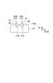
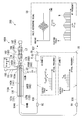
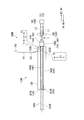
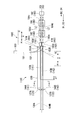
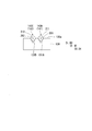
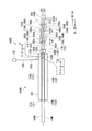
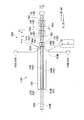
- FIG. 2 is a cross-sectional view of the laser device shown in FIG. 1 as viewed in the direction of arrows YY. It is a top view of a measuring device of a 1st embodiment of the present invention. It is a top view of the laser apparatus of 2nd Embodiment of this invention. It is a top view of the laser apparatus of 3rd Embodiment of this invention.
- FIG. 6 is a cross-sectional view of the laser device shown in FIG. 5 as viewed in the direction of arrows ZZ. It is a top view of the laser apparatus of 4th Embodiment of this invention.
- FIG. 8 is a cross-sectional view of the laser device shown in FIG. 7 taken along the line Y'-Y '; It is a top view of the laser apparatus of 5th Embodiment of this invention. It is a top view of the laser equipment of a 6th embodiment of the present invention. It is a top view of the laser apparatus of 7th Embodiment of this invention. It is a top view of the laser apparatus of 8th Embodiment of this invention. It is a top view of the laser apparatus of 9th Embodiment of this invention.
- FIG. 7 shows a modified example of the laser device shown in FIG. 1 and corresponds to a cross-sectional view taken along line YY in FIG.
- a laser apparatus 160A includes a light source 150, a polarization maintaining optical fiber 151, a polarization separation element 152, polarization maintaining optical fibers 153A and 153B, dual optical frequencies.
- a comb generation optical system 110A is provided.
- One end of the polarization maintaining optical fiber 151 is connected to the light source 150.
- the other end of the polarization maintaining optical fiber 151 is connected to the polarization separation element 152.
- One end of each of the polarization maintaining optical fibers 153A and 153B is connected to the polarization separation element 152.
- the other end of each of the polarization maintaining optical fibers 153A and 153B is connected to the dual optical frequency comb generating optical system 110A.
- the light source 150 is at least a laser beam (first laser beam) S1 whose polarization direction is the first direction P1 with respect to the optical axis A, and a laser whose polarization direction is the second direction with respect to the optical axis A It emits laser light including light (second laser light) S2.
- the optical axis A indicates the traveling direction of light. Assuming that the optical axis A is in a direction perpendicular to the paper surface of FIG. 1, the first direction P1 is a direction facing the upper side and the lower side of the paper, and the second direction P2 is a direction facing the left side and the right is there. Note that the first direction P1 and the second direction P2 may point in any directions as long as they are different from each other.
- the laser beams S1 and S2 may be guided with the slow axis and the fast axis of the polarization maintaining optical fiber 151 as the first direction P1 and the second direction P2.
- the light source 150 according to the first embodiment emits laser beams S1 and S2 and laser beams having any direction different from the first direction P1 and the second direction P2 with respect to the optical axis A. It is composed of a semiconductor laser.
- the polarization separation element 152 extracts only the laser beam S1 from the laser light emitted from the light source 150 to the polarization maintaining optical fiber 153A, and extracts only the laser beam S2 to the polarization maintaining optical fiber 153B.
- the polarization separation element 152 is configured of a polarization maintaining optical coupler.
- the polarization axis of the cladding of the polarization maintaining optical fiber 153A centered on the optical axis A is set so that only the laser beam S1 can be guided by the polarization maintaining optical fiber 153A.
- the polarization axis of the cladding of the polarization maintaining optical fiber 153B centered on the optical axis A is set so that only the laser beam S2 can be guided by the polarization maintaining optical fiber 153B.
- the dual optical frequency comb generation optical system 110A includes a first introduction unit 161, a second introduction unit 162, a first waveguide unit 141, a first reflection unit 121, a second waveguide unit 142, a second reflection unit 122, and light collection.
- a portion (a first light collecting portion, a second light collecting portion) 180 and a third reflecting portion 190 are provided.
- the first introducing unit 161 is connected to the other end of the polarization maintaining optical fiber 153A.
- the second introducing unit 162 is connected to the other end of the polarization maintaining optical fiber 153B.
- the first waveguide portion 141 and the first reflecting portion 121 are provided on the back side in the D1 direction along the D1 direction (first direction) from the first introducing portion 161.
- the second waveguide portion 142 and the second reflecting portion 122 are provided on the back side in the D3 direction along the D3 direction (third direction) from the second introducing portion 162.
- the light collecting section 180 is provided on the near side in the D1 direction from the first introducing part 161 and on the near side in the D3 direction from the second introducing part 162.
- the third reflecting portion 190 is provided on the near side in the D1 direction from the light collecting portion 180.
- the other end side of each of the polarization maintaining optical fibers 153A and 153B is curved so as to merge in the directions D1 and D3 from the laser light introducing direction, and reaches the first introducing portion 161 and the second introducing portion 162.
- the first mode synchronization shift unit E1 is configured.
- the first laser light L1 shifts to the mode synchronization state by the first mode synchronization shift unit E1.
- a second mode synchronization transition unit E2 is configured by the second introduction unit 162, the second waveguide unit 142, the second reflection unit 122, and the portion through which the second laser light passes in the light collection unit 180 and the third reflection unit. Ru.
- the second laser light L2 shifts to the mode synchronization state by the second mode synchronization shift unit E2.
- the first mode synchronization transition portion E1 and the second mode synchronization transition portion E2 are at least partially integrated and extend in the D1 and D3 directions.
- the first introducing portion 161 is configured of an emitting end 165A and a dichroic coating 174.
- the dichroic coatings 174 are provided at intervals on the back side in the D2 direction opposite to the D1 direction.
- the second introducing unit 162 is configured of an emitting end 165 B and a dichroic coating 174.
- the dichroic coating 174 reflects the laser beams S1 and S2 introduced from the first introducing part 161 and the second introducing part 162 into the dual optical frequency comb generating optical system 110A.
- the dichroic coating 174 transmits the laser lights S1 and S2 (hereinafter, referred to as laser amplification lights L1 and L2) amplified by the first waveguide 141 and the second waveguide 142.
- the wavelengths of the laser amplification lights L1 and L2 are different from the wavelengths of the laser lights S1 and S2 before being amplified by the first waveguide 141 and the second waveguide 142.
- the dichroic coating 174 is provided on the end surface of the emission end 165A on the back side in the D1 direction and the end surface of the emission end 165B on the rear side in the D3 direction.
- the position of the dichroic coating 174 is not particularly limited.
- the first waveguide portion 141 is connected to the end on the back side in the D1 direction of the emission end 165A, and guides the laser beam S1 and the laser amplified beam (first laser beam) L1 along the D1 and D2 directions. To amplify.
- the second waveguide 142 is connected to the end on the back side in the D3 direction of the emission end 165B, and along the D4 direction opposite to the D3 direction and the D3 direction, the laser light S2 and the laser amplified light (second laser Light) Wave guide and amplify L2.
- the first waveguide portion 141 is configured of an optical amplification fiber (first waveguide) 143A.
- the second waveguide 142 is configured of an optical amplification fiber (second waveguide) 143B.
- Examples of the optical amplification fibers 143A and 143B of the first embodiment include a polarization-maintaining rare earth-doped optical fiber. As shown in FIG. 2, each of the optical amplification fibers 143A and 143B has a core (first core) 201 and a clad (first clad) 211 provided around the core 201. The cladding 211 has a lower refractive index than the core 201.
- Examples of the rare earth element added to the core 201 of the rare earth-doped optical fiber include erbium (Er), ytterbium (Yb), thulium (Tm) and the like.
- the rare earth element added to the rare earth-doped optical fiber has a wavelength (hereinafter referred to as a first wavelength) of the laser light S1 or S2 before amplification and a wavelength (hereinafter referred to as a second wavelength) of the laser amplification light L1 or L2 It is selected appropriately in consideration.
- the two light amplification fibers 143A and 143B are provided on a common base 130.
- the base 130 is a rectangular solid having substantially the same dimensions as the first waveguide 141 and the second waveguide 142 in the longitudinal direction.
- the first waveguide 141 and the second waveguide 142 are two light amplification fibers 143A and 143B.
- two V-shaped grooves 131 ⁇ / b> A and 131 ⁇ / b> B are formed on the upper surface 130 a of the base 130.
- the grooves 131A and 131B are formed spaced apart from each other in the width direction of the base 130.
- the width direction of the base 130 is a direction parallel to the paper surface of FIG.
- the light amplification fiber 143A is fitted in the groove 131A
- the light amplification fiber 143B is fitted in the groove 131B.
- the material of the base 130 is, for example, metal, resin or the like, but is not particularly limited.
- the optical amplification fibers 143A and 143B have substantially the same length.
- the rear end of the light amplification fibers 143A and 143B in the D1 and D3 directions overlaps the rear end of the base 130 in the D1 and D3 directions.
- the end of the optical amplification fibers 143A and 143B in the near side in the D1 and D3 directions extends further from the end face on the near side in the D1 and D3 directions of the base 130 and is connected to the outgoing ends 165A and 165B. .
- the first reflecting portion 121 and the second reflecting portion 122 are provided on the end surface (end portion) of the base 130 on the back side in the D1 direction.
- the first reflecting portion 121 is connected to the first waveguide portion 141, and reflects a portion of the laser amplified light L1 guided by the first waveguide portion 141 along the D1 direction along the D2 direction.
- the first reflection portion 121 emits the remaining portion of the laser amplified light L1 guided by the first waveguide portion 141 along the D1 direction along the D1 direction.
- the second reflection portion 122 is connected to the second waveguide portion 142, and reflects a portion of the laser amplified light L2 guided by the second waveguide portion 142 along the D3 direction along the D4 direction.
- the second reflector 122 emits the remaining portion of the second laser amplified light L2 guided by the second waveguide 142 along the D3 direction along the D3 direction.
- the power ratios of the laser amplification lights L1 and L2 reflected along the D2 and D4 directions and the laser amplification lights L1 and L2 emitted along the D1 and D3 directions in the first reflection unit 121 and the second reflection unit 122 are Assuming that the total of the laser amplified lights L1 and L2 irradiated to the first reflecting portion 121 and the second reflecting portion 122 is 100, for example, it is about 1:99.
- the polarization maintaining optical fibers 134A and 134B are connected to end portions on the back side in the D1 and D3 directions of the first reflecting portion 121 and the second reflecting portion 122, respectively.
- the polarization maintaining optical fibers 134A and 134B include the optical frequency combs C1 and C2 (first optical frequency comb, second optical frequency comb, see FIG. 3) emitted from the first reflecting portion 121 and the second reflecting portion 122. I will guide.
- the first reflecting portion 121 is configured of the end surface mirror 127A by applying mirror coating to the end surface of the light amplification fiber 143A at the back side in the D1 direction.
- the end surface mirror 127A is integral with the first waveguide 141 and the base 130, and can not be removed from the base 130.
- the mirror coating is applied to the end face of the light amplification fiber 143B on the back side in the D3 direction, so that the second reflection part 122 is configured by the end face mirror 127B.
- the end surface mirror 127B is integral with the second waveguide 142 and the base 130, and can not be removed from the base 130.
- the condensing part 180 is provided with the 1st condensing part 180A and the 2nd condensing part 180B.
- the first light collecting portion 180A and the second light collecting portion 180B are integrated, and their positions are aligned in the second and fourth directions.
- the first light collecting portion 180A and the second light collecting portion 180B are aligned with each other in the second direction and the fourth direction.
- the first condensing unit 180A focuses the laser amplification light L1 emitted from the first introduction unit 161 along the direction D2 on the third reflection unit 190, and the laser amplification light L2 reflected by the third reflection unit 190. Is made incident on the first introduction portion 161 along the direction D1.
- the second light collecting unit 180B focuses the laser amplification light L2 emitted from the second introduction unit 162 along the direction D4 on the third reflection unit 190, and the laser amplification light L2 reflected by the third reflection unit 190. Is made incident on the second introducing portion 162 along the direction D3.
- the condenser unit 180 is configured of two gradient index (GRIN) lenses 182 and 184 spaced apart from each other in the D2 and D4 directions.
- the GRIN lenses 182 and 184 respectively collimate the laser amplified lights L1 and L2 incident on the end surfaces 182c and 184c at the end surfaces 182d and 184d.
- the first mode synchronization transition unit E1 in the GRIN lenses 182 and 184 functions as the first light collector 180A.
- the first mode synchronization transition unit E1 is configured of a portion through which the laser amplification light L1 passes and the vicinity thereof.
- the second mode synchronization transition unit E2 in the GRIN lenses 182 and 184 functions as a second light collector 180B.
- the second mode synchronization transition portion E2 is configured of a portion through which the laser amplification light L2 passes and the vicinity thereof.
- the third reflection portion 190 is provided apart from the end on the near side in the D1 direction of the first waveguide 141 and the end on the near side in the D3 direction of the second waveguide 142.
- the third reflection portion 190 is disposed in the light collection portion 180 near a position spaced apart from the GRIN lens 184 by the focal distance on the front side in the D1 and D3 directions.
- the third reflection portion 190 reflects at least a part of the laser amplified light L1 emitted from the first waveguide portion 141 along the D2 direction, and emits the laser light from the second waveguide portion 142 along the D4 direction. At least a part of the amplified light L2 is reflected.
- the third reflection unit 190 causes the reflected laser amplification light L1 to be incident on the first waveguide 141, and causes the reflected laser amplification light L2 to be incident on the second waveguide 142.
- the reflectances of the laser amplification lights L1 and L2 change according to the powers of the laser amplification lights L1 and L2 irradiated in the condensed state.
- a saturable absorption mirror SAM: Saturable Absorber Mirror
- the SAM is composed of a Distributed Bragg Reflector (DBR) and a saturable absorber.
- DBR Distributed Bragg Reflector
- the DBR is configured of a laminate in which high refractive index materials and low refractive index materials are alternately stacked in the thickness direction.
- the thickness direction is the D1-D4 direction when the DBR is disposed in the dual optical frequency comb generation optical system 110A.
- the absorption by the saturable absorber becomes strong. In this case, most of the laser amplification lights L1 and L2 are absorbed by the saturable absorber, and the laser amplification lights L1 and L2 of a slight power are reflected by the SAM.
- the power of the laser amplification lights L1 and L2 irradiated to the SAM becomes equal to or more than a predetermined value, the absorption in the saturable absorber is saturated. In this case, most of the laser amplification lights L1 and L2 pass through the saturable absorber and are reflected by the DBR, and the high power laser amplification lights L1 and L2 are reflected by the SAM.
- the laser light emitted from the light source 150 is guided to the polarization maintaining optical fiber 151 and enters the polarization separating element 152.
- the polarization separation element 152 separates the laser beams S1 and S2, only the laser beam S1 is guided to the polarization maintaining optical fiber 153A, and only the laser beam S2 is guided to the polarization maintaining optical fiber 153B. .
- the laser beam S1 guided through the polarization maintaining optical fiber 153A passes the emitting end 165A along the direction D2, and is reflected by the dichroic coating 174.
- the laser beam S1 reflected by the dichroic coating 174 passes through the emitting end 165A again, and enters the light amplification fiber 143A along the direction D1.
- the laser beam S2 guided through the polarization maintaining optical fiber 153B passes through the emitting end 165B along the D4 direction and is reflected by the dichroic coating 174.
- the laser beam S2 reflected by the dichroic coating 174 passes through the emitting end 165B again, and enters the light amplification fiber 143B along the direction D3.
- the laser beams S1 and S2 incident on the light amplification fibers 143A and 143B are guided and amplified along the directions D1 and D3. By this, the laser amplified lights L1 and L2 are generated. If the optical amplification fibers 143A and 143B are rare earth-doped optical fibers, the second wavelength is different from the first wavelength.
- the laser amplification light L1 guided by the light amplification fiber 143A along the D1 direction is reflected by the end surface mirror 127A, and is guided by the light amplification fiber 143A along the D2 direction.
- the laser amplification light L2 guided by the light amplification fiber 143B along the D3 direction is reflected by the end face mirror 127B, and is guided by the light amplification fiber 143B along the D4 direction.
- the laser amplification lights L1 and L2 guided by the light amplification fibers 143A and 143B along the directions D2 and D4 pass through the emission ends 165A and 165B and pass through the dichroic coating 174.
- the laser amplified lights L1 and L2 emitted from the dichroic coating 174 along the directions D2 and D4 diffuse in free space and enter the GRIN lens 182.
- the laser amplified lights L1 and L2 incident on the GRIN lens 182 along the directions D2 and D4 are collimated, and then collected by the GRIN lens 184 and incident on the saturable absorption mirror 192.
- a large loss is imparted to the laser amplification lights L1 and L2 incident on the saturable absorption mirror 192 if the power of the collected laser amplification lights L1 and L2 is lower than a predetermined value. If the power of the collected laser amplification lights L1 and L2 is equal to or higher than a predetermined value, a slight loss is given to the laser amplification lights L1 and L2.
- the laser amplified lights L1 and L2 given the loss are reflected by the saturable absorption mirror 192, travel along the directions D1 and D3 and diffuse, and enter the GRIN lens 184.
- the laser amplified lights L1 and L2 incident on the GRIN lens 184 along the D1 and D3 directions are collimated and condensed by the GRIN lens 182.
- the laser amplification lights L1 and L2 collected by the GRIN lens 182 pass through the dichroic coating 174, pass through the emission ends 165A and 165B, and enter the light amplification fibers 143A and 143B.
- the laser amplification lights L1 and L2 incident on the light amplification fibers 143A and 143B along the directions D1 and D3 are repeatedly amplified by the light amplification fibers 143A and 143B.
- the dual optical frequency comb generation optical system 110A and the laser device 160A operate in a state where the laser amplification lights L1 and L2 are continuous lights.
- the dual optical frequency comb generation optical system 110A and the laser device 160A operate in a state where the laser amplification lights L1 and L2 are pulse lights.
- the mode is shifted to the mode synchronization state, and the optical frequency combs C1 and C2 (see FIG. 3) is generated.
- the optical frequency comb C ⁇ b> 1 is led from the first reflector 121 to the polarization maintaining optical fiber 134 ⁇ / b> A.
- the optical frequency comb C2 is led out of the second reflection section 122 to the polarization maintaining optical fiber 134B.
- the repetition frequency f rep1 of the optical frequency comb C1 is determined by the resonator length of the first mode synchronization transition section E1.
- the resonator length of the first mode synchronization transition portion E1 is referred to as a first resonator length.
- the first resonator length corresponds to the length of the light amplification fiber 143A and the length from the near end of the emission end 165A in the D2 direction to the back surface of the saturable absorption mirror 192 in the D2 direction.
- the repetition frequency f rep2 of the optical frequency comb C2 is determined by the resonator length of the second mode synchronization transition portion E2.
- the resonator length of the second mode synchronization transition portion E2 is referred to as a second resonator length.
- the second resonator length corresponds to the length of the light amplification fiber 143B and the length from the near end of the emission end 165B in the D4 direction to the back surface of the saturable absorption mirror 192 in the D4 direction.
- the optical path length of the laser amplification light L1 in the resonator of the first mode synchronization transition portion E1 is determined by the refractive index of the laser amplification light L1 and the first resonator length.
- the optical path length of the laser amplification light L2 in the resonator of the second mode synchronization transition portion E2 is determined by the refractive index of the laser amplification light L2 and the second resonator length.
- the first resonator length and the second resonator length are equal to each other.
- the direction of polarization of the laser amplification light L1 is the first direction P1
- the direction of polarization of the laser amplification light L2 is the second direction P2
- the refractive index of the laser amplification lights L1 and L2 is Different from each other. Therefore, according to the refractive index difference ⁇ n of the laser amplification lights L1 and L2, the optical path length of the laser amplification light L1 with respect to the light amplification fiber 143A of the first mode synchronization transition portion E1 and the light amplification fiber of the second mode synchronization transition portion E2.
- the optical path lengths of the laser amplified light L2 with respect to 143B are different from each other. Assuming that the optical path length difference between the first mode synchronization shift unit E1 and the second mode synchronization shift unit E2 is ⁇ L, the repetition frequency f rep2 is represented by (f rep1 + ⁇ f rep ). The repetition frequency difference ⁇ f rep depends on the optical path length difference ⁇ L.
- the laser amplified light L1 including pulsed light with high intensity is guided along the D1 direction to the polarization maintaining optical fiber 134A .
- the laser amplified light L2 including the pulsed light with high intensity is guided along the D3 direction to the polarization maintaining optical fiber 134B.
- the lengths of the optical amplification fibers 143A and 143B are the repetition of the desired resonator length of the laser amplification lights L1 and L2 and the optical path length difference ⁇ L.
- the frequency is set to correspond to the frequencies f rep1 and f rep2 .
- the laser amplification light L1 is resonated while being shifted to the mode synchronization state at the first mode synchronization transition unit E1.
- the laser amplification light L2 is resonated while being shifted to the mode synchronization state at the second mode synchronization transition unit E2.
- the refractive indexes of the laser amplification lights L1 and L2 are different, and the optical path length of the laser amplification light L1 and the second mode synchronization in the first mode synchronization transition portion E1.
- the optical path lengths of the laser amplified light L2 at the transition portion E2 are different from each other.
- the refractive indexes of the laser amplification lights L1 and L2 are made different from each other by using the laser lights S1 and S2 and the laser amplification lights L1 and L2 having different polarization directions.
- the first resonator length and the second resonator length can be made different from each other.
- the first waveguide portion 141 and the second waveguide portion 142 are provided on the common base 130, and the first mode synchronization transition portion E1 and the second mode synchronization transition The part E2 shares the light collecting part 180 and the third reflecting part 190.
- environmental disturbances and mechanical disturbances received by the mode-locked laser that is, the configuration related to mode synchronization of the laser amplified lights L1 and L2
- Environmental disturbance and mechanical disturbance can be easily removed as common noise between the first mode synchronization transition unit E1 and the second mode synchronization transition unit E2, and the relative SN ratio of the optical frequency combs C1 and C2 can be increased. . By this, it is possible to increase the SN ratio of the interference signal by the optical frequency combs C1 and C2 and to increase the measurement accuracy.
- the first waveguide portion 141 and the second waveguide portion 142 are provided on the common base 130, and the first mode synchronization transition portion E1 and the second mode synchronization transition The part E2 shares the light collecting part 180 and the third reflecting part 190.
- the measurement apparatus 200 includes a laser device 160A having a dual optical frequency comb generation optical system 110A, an interference unit 59, and a sample information extraction unit 58.
- the interference unit 59 causes the polarization maintaining optical fibers 134A and 134B for output and the optical frequency combs C1 and C2 to interfere with each other.
- the sample information extraction unit 58 extracts the information of the sample from the interference signals of the optical frequency combs C1 and C2 which are interfered by the interference unit 59.
- the optical frequency comb C1 generated by the laser device 160A is emitted from the emission end 91 through the polarization maintaining optical fiber 134A.
- the optical frequency comb C2 generated by the laser device 160A is emitted from the emission end 92 through the polarization maintaining optical fiber 134B.
- the sample S to be measured by the measuring apparatus 200 is disposed on the path X36 of the optical frequency comb C2.
- a mirror 55 is provided along the path X35 of the optical frequency comb C1 to turn the path X35 toward the interference unit 59.
- the interference unit 59 causes the optical frequency comb C1 and the optical frequency comb C2 including the information of the sample S to interfere with each other.
- the optical frequency comb C2 including the information of the sample S is referred to as an optical frequency comb C3.
- the interference unit 59 is disposed on the back side of the traveling direction of the optical frequency comb C3 with respect to the sample S, and is configured of a light beam splitter or a half mirror. In the first embodiment, the polarization directions of the optical frequency combs C1 and C2 are different from each other.
- the mirror 55 and the interference unit 59 are preferably polarization maintaining.
- polarization maintaining the polarization maintaining optical fiber 134A or the polarization maintaining optical fiber 134B is temporarily cut halfway and the polarization is maintained
- the optical fibers 134A or the polarization-maintaining optical fibers 134B may be aligned and fused so that their slow or fast axes are orthogonal in cross section.
- the output end 91 may be set to be rotated by 90 ° with respect to the polarization maintaining optical fiber 134A.
- the output end 92 may be installed rotated 90 degrees with respect to the polarization maintaining optical fiber 134B.
- the sample information extraction unit 58 is disposed at the back side in the traveling direction of the multiheterodyne signal (interference signal) generated when the optical frequency combs C1 and C3 interfere with each other in the interference unit 59.
- the sample information extraction unit 58 is capable of acquiring information on the sample S from the multiheterodyne signal, and is configured of a generally known optical system. As such an optical system, an apparatus etc. which convert into an electric signal by a light receiver are mentioned, for example.
- the optical frequency comb C2 travels along the path X36 and passes through the sample S.
- optical information possessed by the sample S is added to the optical frequency comb C2 to become an optical frequency comb C3.
- the optical frequency comb C1 travels along the path X35 and is turned back by the mirror 55.
- the optical frequency comb C3 traveling along the path X36 and the optical frequency comb C1 traveling along the path X35 are combined in the interference unit 59 and interfere with each other. Interference of the optical frequency combs C1, C3 produces a multiheterodyne signal.
- the multiheterodyne signal travels along the path X 37 and enters the sample information extraction unit 58.
- the sample information extraction unit 58 the multiheterodyne signal is converted into a mode decomposition spectrum of a high frequency band by, for example, Fast Fourier Transform (FFT).
- FFT Fast Fourier Transform
- Optical information of the sample S is extracted from the waveform W of the mode decomposition spectrum.
- the waveform W is shown by a broken line.
- the frequency interval between adjacent spectra on the frequency axis in the mode decomposition spectrum corresponds to the repetition frequency difference ⁇ f rep .
- optical information of the sample S can be added to the optical frequency comb C2 traveling on the path X36.
- the interference unit 59 eliminates the environmental disturbance and mechanical disturbance commonly included in the optical frequency combs C1 and C3 by causing the optical frequency combs C1 and C3 to interfere with each other, and can be easily observed in the high frequency band.
- a mode resolved spectrum can be obtained.
- the sample information extraction unit 58 can extract the information of the sample S from the waveform W of the spectrum distribution of the obtained mode decomposition spectrum. Therefore, according to the measuring apparatus 200 according to the present invention, since the optical frequency combs C1 and C2 having a high SN ratio are used, the information of the sample S can be acquired with high accuracy.
- the measuring device is achieved by bringing the component parts of the waveguide close to each other and fixing them to the common base 130 and sharing the components of the free space system. 200 can be miniaturized.
- a laser apparatus 160B includes a dual optical frequency comb generation optical system 110B in place of the dual optical frequency comb generation optical system 110A of the first embodiment.
- the configuration from the light source 150 to the emitting end (first introducing portion, second introducing portion) 165C in the laser device 160B is the first introducing portion 161 to the second introducing portion from the light source 150 in the laser device 160A described in the first embodiment. It is similar to the configuration up to 162.
- the emission ends 165A and 165B in the dual optical frequency comb generation optical system 110A are replaced with the emission end 165C.
- the GRIN lenses 182 and 184 in the dual optical frequency comb generation optical system 110 A are replaced with a convex lens 186. That is, the first introducing portion 161 and the second introducing portion 162 of the dual optical frequency comb generation optical system 110A are configured by the emission end 165C of the dual optical frequency comb generation optical system 110B.
- the condensing part 180 of the dual optical frequency comb generation optical system 110A is configured by the convex lens 186 of the dual optical frequency comb generation optical system 110B.
- the emitting end 165C is connected to the other end of each of the polarization maintaining optical fibers 153A and 153B.
- the emitting end 165C is configured as the polarization maintaining optical fibers 153A and 153B attached to one collimator lens.
- the emitting end 165C collimates the laser amplified lights L1 and L2 incident from the front side in the D2 and D4 directions, and emits obliquely toward the back side in the D2 and D4 directions.
- the emitting end 165C brings the laser amplified lights L1 and L2 emitted apart from each other in a plane including the directions D2 and D4 close to each other. Thereafter, the emission ends 165C are separated at a predetermined position T after being crossed.
- An example of the emitting end 165C is Dual Fiber Collimator (commercially available: AFR (Advanced Fiber Resources, Ltd.), model number: C-1.8-2-55, etc.).
- the laser amplified lights L1 and L2 overlap with each other at the predetermined position T and then travel away from each other again to the far side in the D2 and D4 directions.
- the convex lens 186 returns the traveling direction of the laser amplification lights L1 and L2 to be parallel to the D2 and D4 directions.
- the convex lens 186 causes the third reflected portion 190 to focus the laser amplified lights L1 and L2.
- the third reflective portion 190 is disposed in the vicinity of the focal length of the convex lens 186.
- the laser amplified lights L1 and L2 enter the emission end 165C from the near side in the D2 and D4 directions, are collimated, and are on the far side in the D2 and D4 directions. Directly to emit.
- the laser amplified lights L1 and L2 are separated from each other in a plane including the directions D2 and D4 and are emitted from the emission end 165C, crossed at a predetermined position T, and then separated from each other. After that, the laser amplification lights L1 and L2 are condensed by the convex lens 186 and enter the saturable absorption mirror 192.
- the laser amplified lights L1 and L2 are reflected by the DBR of the saturable absorbing mirror 192, and travel in the same path as when entering the saturable absorbing mirror 192 in the opposite direction to that when entering.
- the laser device 160B basically has the same effect as the laser device 160A because it has the dual optical frequency comb generation optical system 110B.
- the light collecting unit 180 is configured of a single convex lens 186.
- the configuration of the light collecting unit 180 includes all the configurations capable of irradiating the third reflection unit with the laser amplification lights L1 and L2 in a collected state.
- the condensing part 180 is not limited to the GRIN lenses 182 and 184 and the convex lens 186.
- the measurement device of the second embodiment includes a laser device 160B shown in FIG. 4 instead of the laser device 160A of the measurement device 200 shown in FIG.
- the configuration of the measurement apparatus according to the second embodiment other than the laser apparatus is the same as that of the measurement apparatus 200.
- optical frequency combs C1 and C2 are obtained from the polarization maintaining optical fibers 134A and 134B as in the laser device 160A.
- the measuring device of the second embodiment operates in the same manner as the measuring device 200, and exhibits the same effects as the measuring device 200. According to the laser device 160B, the repetition frequency difference ⁇ f rep between the optical frequency combs C1 and C2 can be easily controlled.
- the laser apparatus 160C of the third embodiment to which the present invention is applied is replaced by the dual optical frequency comb generation optical system 110A described in the first embodiment, and the dual optical frequency comb generation optical system 110C is used.
- the configuration from the light source 150 to the emitting end (first introducing portion, second introducing portion) 165A, 165B in the laser device 160C is the first introducing portion 161 and the second introducing portion 161 from the light source 150 in the laser device 160A described in the first embodiment.
- the configuration is similar to that of the introduction unit 162.
- the first waveguide portion 141 is configured of an optical amplification fiber 143A and an optical fiber 144A.
- the near end of the optical fiber 144A in the D1 direction is connected to the far end of the light amplification fiber 143A in the D1 direction.
- the second waveguide 142 is configured of an optical amplification fiber 143B and an optical fiber 144B.
- the near end of the optical fiber 144B in the D3 direction is connected to the far end of the light amplification fiber 143B in the D3 direction.
- No rare earth element is added to the core 202 (see FIG. 6) of each of the optical fibers 144A and 144B.
- the optical fiber 144A only guides the laser amplification light L1 and does not amplify it.
- the optical fiber 144B only guides the laser amplification light L2 and does not amplify it.
- the D1 direction and the D3 direction are parallel to each other.
- the length of the light amplification fiber 143A in the first waveguide portion 141 is longer than the light amplification fiber 143B in the second waveguide portion 142 by the length ⁇ F. Since the length of the optical fiber 144A is shorter than the length of the optical fiber 144B by the length ⁇ F, the first waveguide 141 and the second waveguide 142 have substantially the same length.
- the two optical fibers 144A and 144B are provided on a common base 130 with the two optical amplification fibers 143A and 143B.
- the base 130 has substantially the same dimensions as the first waveguide 141 and the second waveguide 142 in the longitudinal direction.
- the optical fiber 144A is fitted in the groove 131A
- the optical fiber 144B is fitted in the groove 131B.
- the end surface mirror 127A of the first reflecting portion 121 is connected to the end on the back side in the D1 direction of the optical fiber 144A.
- the end surface mirror 127B of the second reflecting portion 122 is connected to the end on the back side in the D3 direction of the optical fiber 144B.
- the rear end of the optical fibers 144A and 144B in the D1 and D3 directions overlaps the rear end of the base 130 in the D1 and D3 directions.
- the polarization direction of the laser beam S1 and the polarization direction of the laser beam S2 do not necessarily have to be different from each other.
- the light source 150 may emit laser beams S1 and S2 whose polarization direction with respect to the optical axis A is only the first direction P1.
- the laser beams S1 and S2 can be guided by aligning the polarization direction only with the slow axis or only with the fast axis of the polarization maintaining optical fiber 151.
- the light source 150 of the third embodiment is configured of a semiconductor laser that emits at least laser beams S1 and S2.
- the laser amplification light L1 is guided through the optical fiber 144A. Thereafter, the laser amplification light L1 is reflected by the end face mirror 127A, guided through the optical fiber 144A along the direction D2, and guided through the optical amplification fiber 143A and amplified.
- the laser amplified light L2 is guided through the optical fiber 144B. Thereafter, the laser amplification light L2 is reflected by the end face mirror 127B, and after being guided through the optical fiber 144B along the direction D4, is guided through the optical amplification fiber 143B.
- the first resonator length and the second resonator length are equal to each other.
- the direction of polarization of the laser amplification lights L1 and L2 may be the common first direction P1
- the lengths of the light amplification fibers 143A and 143B differ by ⁇ F.
- the optical path length of the laser amplification light L1 with respect to the optical amplification fiber 143A of the first mode synchronization transition portion E1 and the optical path length of the laser amplification light L2 with respect to the optical amplification fiber 143B of the second mode synchronization transition portion E2 are different from each other.
- the optical path length difference ⁇ L between the first mode synchronization transition portion E1 and the second mode synchronization transition portion E2 is determined by the length ⁇ F.
- the repetition frequency f rep2 is represented by (f rep1 + ⁇ f rep ).
- the repetition frequency difference ⁇ f rep depends on the optical path length difference ⁇ L.
- the laser amplified light L1 including pulsed light with high intensity is guided along the D1 direction to the polarization maintaining optical fiber 134A .
- the laser amplified light L2 including high intensity pulsed light is guided to the polarization maintaining optical fiber 134B along the D3 direction.
- the length ⁇ F is set such that the resonator length of the laser amplification lights L1 and L2 and the optical path length difference ⁇ L correspond to desired repetition frequencies f rep1 and f rep2 .
- the refractive index of the core of the optical fibers 144A and 144B at a wavelength of 1550 nm is about 1.468
- the refractive index of the core of the optical amplification fibers 143A and 143B at a wavelength of 1550 nm is about 1.48.
- the cores of the optical amplification fibers 143A and 143B absorb the rare earth atoms, the above-described refractive index changes depending on the doping concentration of the rare earth atoms and the power of the excitation light.
- the length of the space in the dual optical frequency comb generation optical system 110C is fixed to 10 cm
- the length of the optical fiber 144A is 10 cm
- the length of the optical amplification fiber 143A is 20 cm.
- the length of the space in the dual optical frequency comb generation optical system 110C is the distance between the end face on the back side in the D2 and D4 directions of the base 130 and the reflecting surface of the third reflecting portion 190.
- the length of the optical fiber 144B is 15 cm
- the length of the optical amplification fiber 143B is 15 cm.
- the physical lengths of the first waveguide 141 and the second waveguide 142 are equal to each other and 40 cm.
- the optical path length of the first waveguide 141 and the optical path length of the second waveguide 142 differ by 0.6 mm.
- Such an optical path length difference means that the length ⁇ F is 0.05 mm. If the length ⁇ F is 0.05 mm, the repetition frequency f rep1 becomes 552.3946024 MHz, the repetition frequency f rep2 becomes 552.9185872 MHz, and the ⁇ f rep becomes about 0.611 MHz.
- the laser device 160C basically has the same effect as the laser device 160A because it has the dual light frequency comb generation optical system 110C.
- the length ⁇ F is a parameter fixed at the time of manufacturing the optical amplification fibers 143A and 143B. Therefore, the length ⁇ F can be adjusted with high accuracy compared to parameters (such as the wavelength of the laser amplification lights L1 and L2 and the direction of polarization) that are easily influenced by the environment around the dual optical frequency comb generation optical system 110C. That is, it is possible to design correctly in advance and is stable.
- the repetition frequency difference ⁇ f rep between the optical frequency combs C1 and C2 can be controlled by the length ⁇ F.
- the length ⁇ F By changing the length ⁇ F, the dispersion amount of the optical frequency combs C1 and C2 can be changed.
- the width of the spectrum of the optical frequency combs C1 and C2 can be changed.
- the measurement device of the third embodiment includes a laser device 160C shown in FIG. 5 instead of the laser device 160A of the measurement device 200 shown in FIG.
- the configuration of the measurement device of the third embodiment other than the laser device 160C is the same as that of the measurement device 200.
- the directions of polarization of the laser amplified lights L1 and L2 may be the same in the first direction P1. Therefore, the mirror 55 and the interference unit 59 do not have to be of the polarization maintaining type.
- the mirror 55 and the interference unit 59 may be configured by an optical component or the like that does not hold the direction of polarization of the optical frequency combs C1 and C3.
- optical frequency combs C1 and C2 are obtained from the polarization maintaining optical fibers 134A and 134B as in the laser device 160A.
- the measuring device of the third embodiment operates in the same manner as the measuring device 200, and exhibits the same effects as the measuring device 200.
- the repetition frequency difference ⁇ f rep between the light frequency combs C1 and C2 can be easily and accurately controlled. By this, it is possible to control the frequency interval between adjacent spectra on the frequency axis in the mode decomposition spectrum with high accuracy.
- the measuring apparatus of the third embodiment the measurement resolution can be easily and accurately adjusted.
- the width of the spectrum of the optical frequency combs C1 and C2 can be adjusted in the laser device 160C, and the measurement band can be easily and accurately adjusted.
- a laser apparatus 160A ' according to the fourth embodiment of the present invention replaces the dual optical frequency comb generation optical system 110A described in the first embodiment with a dual optical frequency comb generation optical system 110A'.
- the configuration from the light source 150 to the emission end (first introducing portion, second introducing portion) 165A, 165B in the laser device 160A ′ is the same as the configuration from the light source 150 in the laser device 160A described in the first embodiment.
- the configuration is the same as that of the second introduction unit 162.
- the dual optical frequency comb generation optical system 110A ′ is an optical system in which the optical amplification fiber 143B of the second waveguide 142 in the dual optical frequency comb generation optical system 110A is replaced with an optical amplification fiber (second waveguide) 143C.
- the optical amplification fiber 143 ⁇ / b> C has a core (second core) 202 and a clad (second clad) 212 provided around the core 202.
- the core 202 has a refractive index different from that of the core 201 of the light amplification fibers 143A and 143B of the first embodiment.
- the cladding 212 has a lower refractive index than the core 202.
- the rare earth element added to the core 202 is preferably the same as the rare earth element added to the core 201.
- the types of rare earth elements to be added are the same in the cores 201 and 202.
- the addition concentrations to which the rare earth elements are added are different from one another.
- the addition concentration of the rare earth element to each of the cores 201 and 202 may be the same, and the diameters of the cores 201 and 202 may be different from each other.
- the cladding 212 may be composed of the same composition as the cladding 211 of the optical amplification fibers 143A and 143B, or may be composed of a composition different from that of the cladding 211 as long as it has a refractive index lower than that of the core 202.
- the direction of polarization of the laser beam S1 and the direction of polarization of the laser beam S2 do not necessarily have to be different from each other.
- the light source 150 may emit laser beams S1 and S2 whose polarization direction is only the first direction P1 with respect to the optical axis A.
- the laser beams S1 and S2 can be guided with only the slow axis or only the fast axis of the polarization maintaining optical fiber 151 in the first direction P1.
- the laser amplification light L2 that has passed through the emission end 165B along the D3 direction is guided through the light amplification fiber 143C and amplified.
- the laser amplification light L2 is reflected by the end face mirror 127B, is guided through the light amplification fiber 143C along the direction D4, is amplified, and passes through the emission end 165B again.
- the first resonator length and the second resonator length are equal, and the polarization directions of the laser amplified lights L1 and L2 may be the first direction P1 in common.
- the refractive index of the core 201 of the optical amplification fiber 143A and the refractive index of the core 202 of the optical amplification fiber 143C differ by ⁇ n.
- the optical path length of the laser amplification light L1 with respect to the optical amplification fiber 143A of the first mode synchronization transition portion E1 and the optical path length of the laser amplification light L2 with respect to the optical amplification fiber 143B of the second mode synchronization transition portion E2 are different from each other.
- the optical path length difference ⁇ L between the first mode synchronization transition portion E1 and the second mode synchronization transition portion E2 is determined by the refractive index difference ⁇ n.
- the repetition frequency f rep2 is represented by (f rep1 + ⁇ f rep ).
- the repetition frequency difference ⁇ f rep depends on the optical path length difference ⁇ L.
- the laser amplification light L1 including pulsed light with high intensity is guided to the polarization maintaining optical fiber 134A along the D1 direction. Be done.
- the laser amplified light L2 including high intensity pulsed light is guided to the polarization maintaining optical fiber 134B along the D3 direction.
- the length ⁇ F is set such that the resonator length of the laser amplification lights L1 and L2 and the optical path length difference ⁇ L correspond to desired repetition frequencies f rep1 and f rep2 .
- the optical amplification fiber 143A and the optical amplification fiber 143C have a nonlinear refractive index of 0.4 ⁇ 10 -16 cm 2 / W different.
- the refractive index difference ⁇ n can be set as 0.4 ⁇ 10 ⁇ 16 cm 2 / W.
- the length ⁇ n is a parameter fixed at the time of manufacture of the optical amplification fibers 143A and 143C, and a parameter (wavelengths of the laser amplification lights L1 and L2) susceptible to the environment around the dual optical frequency comb generation optical system 110A ′. And can be adjusted with high accuracy as compared with the direction of polarization, etc., and can be designed accurately in advance and is stable.
- the repetition frequency difference ⁇ f rep between the optical frequency combs C1 and C2 can be controlled by the length ⁇ F that can be adjusted with high accuracy.
- the laser amplification lights L1, L1 in the cores 201, 202 are made different from each other by making the addition concentrations of the rare earth elements in the cores 201, 202 different to change the refractive index difference ⁇ n.
- the amount of absorption of L2 can be changed to change the amount of dispersion of the optical frequency combs C1 and C2.
- the width of the spectrum of the optical frequency combs C1 and C2 can be changed.
- the measurement device of the fourth embodiment includes a laser device 160A ′ shown in FIG. 7 in place of the laser device 160A of the measurement device 200 shown in FIG.
- the configuration of the measurement device of the fourth embodiment other than the laser device 160A ′ is the same as that of the measurement device 200.
- the directions of polarization of the laser amplified lights L1 and L2 may be the same in the first direction P1. Therefore, the mirror 55 and the interference unit 59 do not have to be of the polarization maintaining type.
- the mirror 55 and the interference unit 59 may be configured by an optical component or the like that does not hold the direction of polarization of the optical frequency combs C1 and C3.
- the optical frequency combs C1 and C2 are emitted from the polarization maintaining optical fibers 134A and 134B as in the laser device 160A.
- the measuring device of the fourth embodiment operates in the same manner as the measuring device 200, and exhibits the same effects as the measuring device 200.
- the frequency interval between adjacent spectra on the frequency axis in the mode decomposition spectrum can be made highly accurate. It can control.
- the measurement resolution can be easily and accurately adjusted.
- the measurement band can be easily and accurately adjusted by adjusting the width of the spectrum of the optical frequency combs C1 and C2 in the laser device 160A ′.
- the laser apparatus 160D of the fifth embodiment to which the present invention is applied is replaced with the dual optical frequency comb generation optical system 110A described in the first embodiment, and the dual optical frequency comb generation optical system 110D is used.
- the configuration from the light source 150 to the emission end (first introducing portion, second introducing portion) 165A, 165B in the laser device 160D is the first introducing portion 161 and the second introducing portion 161 from the light source 150 in the laser device 160A described in the first embodiment.
- the configuration is similar to that of the introduction unit 162.
- the GRIN lens 182 is configured of GRIN lens portions 182A and 182B integrated with each other. Being integrated with one another means that the relative position of the GRIN lens portions 182A and 182B is fixed.
- the GRIN lens portion 182A functioning as the first light collecting portion 180A and the GRIN lens portion 182B functioning as the second light collecting portion 180B have substantially the same length in the D2 direction or the D4 direction, but in the D2 and D4 directions The positions at the positions are shifted by a length .DELTA.M. In the D2 and D4 directions, the distance from the rear end of the dichroic coating 174 to the front end 182c of the GRIN lens portion 182A and the rear end of the dichroic coating 174 from the rear end of the GRIN lens 182B The distance to the end face 182c of the two differs by a length ⁇ M.
- the GRIN lens 184 is composed of GRIN lens portions 184A and 184B integrated with each other. Being integrated with one another means that the relative position of the GRIN lens portions 184A and 184B is fixed.
- the GRIN lens portion 184A functioning as the first light collecting portion 180A and the GRIN lens portion 184B functioning as the second light collecting portion 180B have substantially the same length in the D2 and D4 directions, but in the D2 and D4 directions The position is shifted by a length ⁇ M '.
- the distance to the end face 184 d of the two differs by a length ⁇ M ′.
- positions irradiated with each of the laser amplification lights L1 and L2 on the end face of the saturable absorption mirror 192 in the D2 and D4 directions are shifted by a length ⁇ J in the D2 direction or D4 direction.
- the distance between the position where the laser amplification light L2 is emitted from the end face on the back side of the dichroic coating 174 in the direction and the position where the laser amplification light L2 is irradiated to the end face on the near side of the saturable absorption mirror 192 is It differs by ⁇ J.
- the direction of polarization of the laser beam S1 and the direction of polarization of the laser beam S2 do not necessarily have to be different from each other.
- the light source 150 may emit laser beams S1 and S2 whose polarization direction is common to the optical axis A and which has only the first direction P1.
- the laser beams S1 and S2 can be guided with only the slow axis or only the fast axis of the polarization maintaining optical fiber 151 in the first direction P1.
- the first resonator length and the second resonator length are equal to each other, and the polarization directions of the laser amplification lights L1 and L2 are the same in the first direction P1.
- the positions of the GRIN lens portions 182A and 182B differ by the length ⁇ M in the D2 and D4 directions, and the positions of the GRIN lens portions 184A and 184B are the length ⁇ M ′
- the position where the laser amplification lights L1 and L2 are irradiated to the saturable absorption mirror 192 differs by a length ⁇ J.
- the optical path length difference ⁇ L between the first mode synchronization transition portion E1 and the second mode synchronization transition portion E2 is determined by the lengths ⁇ M, ⁇ M ′ and ⁇ J.
- the repetition frequency f rep2 is represented by (f rep1 + ⁇ f rep ). The repetition frequency difference ⁇ f rep depends on the optical path length difference ⁇ L.
- the laser amplification light L1 including pulsed light with high intensity is guided along the D1 direction to the polarization maintaining optical fiber 134A .
- the laser amplified light L2 including high intensity pulsed light is guided to the polarization maintaining optical fiber 134B along the D3 direction.
- the lengths .DELTA.M , .DELTA.M ' and .DELTA.J are set such that the resonator length of the laser amplification lights L1 and L2 and the optical path length difference .DELTA.L correspond to the desired repetition frequencies f rep1 and f rep2 .
- the lengths ⁇ M, ⁇ M ′, and ⁇ J are small lengths, and are caused by manufacturing errors that occur when arranging each component of the dual optical frequency comb generation optical system 110D, when manufacturing the laser device 160D, etc. It may occur or may occur intentionally.
- the laser device 160D basically has the same effect as the laser device 160A because it has the dual optical frequency comb generation optical system 110D.
- the lengths ⁇ M, ⁇ M ′ and ⁇ J are parameters fixed at the time of construction of the dual optical frequency comb generation optical system 110D, and parameters (laser amplified light) that are easily affected by the environment and the like of the dual optical frequency comb generation optical system 110D It can be adjusted with high accuracy as compared with the wavelengths of L1 and L2 and the direction of polarization, etc., and can be designed in advance accurately and is stable.
- the repetition frequency difference ⁇ f rep between the optical frequency combs C1 and C2 can be controlled by the lengths ⁇ M, ⁇ M ′, ⁇ J that can be adjusted with high accuracy.
- the measurement device of the fifth embodiment includes a laser device 160D shown in FIG. 9 in place of the laser device 160A of the measurement device 200 shown in FIG.
- the configuration of the measurement device of the fifth embodiment other than the laser device 160D is the same as that of the measurement device 200.
- the directions of polarization of the laser amplified lights L1 and L2 may be the same in the first direction P1. Therefore, the mirror 55 and the interference unit 59 need not be of the polarization maintaining type.
- the mirror 55 and the interference unit 59 may be configured by an optical component or the like that does not hold the direction of polarization of the optical frequency combs C1 and C3.
- optical frequency combs C1 and C2 are emitted from the polarization maintaining optical fibers 134A and 134B as in the laser device 160A.
- the measuring device of the fifth embodiment operates in the same manner as the measuring device 200, and exhibits the same effects as the measuring device 200.
- the repetition frequency difference ⁇ f rep between the optical frequency combs C1 and C2 can be easily and accurately controlled. Therefore, in the mode decomposition spectrum, the frequency interval between adjacent spectra on the frequency axis can be controlled with high precision.
- the measuring apparatus of the fifth embodiment the measurement resolution can be easily and accurately adjusted.
- the positions of the GRIN lens portions 182A and 182B are shifted by the length ⁇ M, the relative positions of the GRIN lens portions 184A and 184B are even, and the saturable absorbing mirror 192
- the positions of the end faces on the near side in the D2 direction or the D4 direction may be aligned.
- the length ⁇ M is set such that the resonator length of the laser amplification lights L1 and L2 and the optical path length difference ⁇ L correspond to the desired repetition frequency ⁇ f rep .
- the position of the laser amplification lights L1 and L2 is deviated by the length ⁇ J due to the deviation of the end surface of the saturable absorption mirror 192 in the D2 direction or the D4 direction, the relative position of the GRIN lens portions 182A and 182B, and GRIN
- the relative positions of the lens portions 184A and 184B may be aligned.
- the length ⁇ J is set such that the resonator length of the laser amplification lights L1 and L2 and the optical path length difference ⁇ L correspond to the desired repetition frequency ⁇ f rep .
- positions where the portion that configures the first mode synchronization transition portion E1 of the GRIN lens 184 and the portion that configures the second mode synchronization transition portion E2 differ from each other in the D2 and D4 directions. It may be misplaced.
- a laser apparatus 160E includes a dual optical frequency comb generation optical system 110E in place of the dual optical frequency comb generation optical system 110A described in the first embodiment.
- the configuration from the light source 150 to the emitting end (first introducing portion, second introducing portion) 165A, 165B in the laser device 160E is the first introducing portion 161 and the second introducing portion 161 from the light source 150 in the laser device 160A described in the first embodiment.
- the configuration is similar to that of the introduction unit 162.
- the position of the reflecting surface on the near side in the D1 and D3 directions of the end surface mirror 127A and the position of the reflecting surface on the near side in the D1 and D3 directions of the end surface mirror 127B are It differs by the length ⁇ G.
- the length of the light amplification fiber 143A along the D1 and D2 directions and the length of the light amplification fiber 143B along the D3 and D4 directions are different from each other. In the configuration example shown in FIG. 10, the length of the light amplification fiber 143A is shorter than the length of the light amplification fiber 143B by the length ⁇ G.
- the end surface mirror 127B is disposed on the near side of the end surface on the back side in the direction D1 of the base 130.
- a groove is formed on the upper surface of the base 130 along the height direction of the base 130.
- the end surface mirror 127 B is fitted in the groove and is perpendicular to the top surface of the base 130.
- the end face on the near side in the D1 direction of the end face mirror 127B is in contact with the end face on the back side in the D1 direction of the light amplification fiber 143B.
- the direction of polarization of the laser beam S1 and the direction of polarization of the laser beam S2 do not necessarily have to be different from each other.
- the light source 150 may emit laser beams S1 and S2 whose polarization direction with respect to the optical axis A is only the first direction P1.
- the laser beams S1 and S2 can be guided with only the slow axis or only the fast axis of the polarization maintaining optical fiber 151 in the first direction P1.
- the polarization directions of the laser amplification lights L1 and L2 may be the first direction P1 in common.
- the length of the light amplification fiber 143A in the D1 and D3 directions and the length of the light amplification fiber 143B in the D2 and D4 directions differ by a length ⁇ G.
- the first resonator length and the second resonator length differ by a length ⁇ G.
- the optical path length difference ⁇ L between the first mode synchronization transition portion E1 and the second mode synchronization transition portion E2 is directly determined by the length ⁇ G.
- the repetition frequency f rep2 is represented by (f rep1 + ⁇ f rep ).
- the repetition frequency difference ⁇ f rep depends on the optical path length difference ⁇ L.
- the laser amplification light L1 including pulsed light with high intensity is guided along the D1 direction to the polarization maintaining optical fiber 134A .
- the laser amplified light L2 including high intensity pulsed light is guided to the polarization maintaining optical fiber 134B along the D3 direction.
- the length ⁇ G is set such that the resonator length of the laser amplification lights L1 and L2 and the optical path length difference ⁇ L correspond to the desired repetition frequencies f rep1 and f rep2 .
- the length of the space is fixed at 10 cm.
- the distance between the end face on the back side in the D 2 and D 4 directions of the base 130 and the reflecting surface of the third reflecting portion 190 is 10 cm.
- the refractive index of the core of each of the optical amplification fibers 143A and 143B is assumed to be 1.48. In such a case, if the length of the optical amplification fiber 143A is 1 m, the length of the optical amplification fiber 143B is 1.001 m, and the length ⁇ G is 1 mm, the repetition frequency difference ⁇ f rep is 0.178 MHz.
- the length ⁇ G is a parameter fixed at the time of installation of the end face mirror 127B on the base 130, and a parameter (wavelength of the laser amplification lights L1 and L2) susceptible to the environment around the dual optical frequency comb generation optical system 110E And can be adjusted with high accuracy as compared with the direction of polarization, etc., and can be designed accurately in advance and is stable.
- the repetition frequency difference ⁇ f rep between the optical frequency combs C1 and C2 can be controlled by the length ⁇ G that can be adjusted with high accuracy.
- the length ⁇ G By changing the length ⁇ G, the dispersion amount of the optical frequency combs C1 and C2 can be made different according to the length ⁇ G.
- the spectrum width of the optical frequency combs C1 and C2 can be changed by changing the dispersion amount of the optical frequency combs C1 and C2.
- the measurement device of the sixth embodiment includes a laser device 160E shown in FIG. 10 in place of the laser device 160A of the measurement device 200 shown in FIG.
- the configuration of the measurement device of the sixth embodiment other than the laser device 160E is the same as that of the measurement device 200.
- the directions of polarization of the laser amplified lights L1 and L2 may be the same in the first direction P1. Therefore, the mirror 55 and the interference unit 59 do not have to be of the polarization maintaining type.
- the mirror 55 and the interference unit 59 may be configured by an optical component or the like that does not hold the direction of polarization of the optical frequency combs C1 and C3.
- the optical frequency combs C1 and C2 are emitted from the polarization maintaining optical fibers 134A and 134B.
- the measuring device of the sixth embodiment operates in the same manner as the measuring device 200, and exhibits the same effects as the measuring device 200.
- the laser device 160E since the repetition frequency difference ⁇ f rep between the optical frequency combs C1 and C2 can be easily and accurately controlled, the frequency interval between adjacent spectra on the frequency axis in the mode decomposition spectrum is accurately controlled. it can.
- the measurement resolution can be easily and accurately adjusted.
- the measurement band can be easily and accurately adjusted by adjusting the width of the spectrum of the optical frequency combs C1 and C2 in the laser device 160E.
- the laser apparatus 160F of the seventh embodiment to which the present invention is applied is replaced by the dual optical frequency comb generation optical system 110A described in the first embodiment, and the dual optical frequency comb generation optical system 110F is used.
- the configuration from the light source 150 to the emitting end (first introducing portion, second introducing portion) 165A, 165B in the laser device 160F is the first introducing portion 161 and the second introducing portion 161 from the light source 150 in the laser device 160A described in the first embodiment.
- the configuration is similar to that of the introduction unit 162.
- the dual optical frequency comb generation optical system 110F is an optical system in which the end face mirrors 127A and 127B in the dual optical frequency comb generation optical system 110A are replaced with fiber Bragg gratings (FBG) 128A and 128B.
- the FBGs 128A and 128B are detachably disposed to the optical amplification fibers 143A and 143B on the near side in the D1 direction or the D2 direction using a connector (not illustrated) or the like.
- the FBGs 128A and 128B are detachably disposed to the polarization maintaining optical fibers 134A and 134B on the back side in the D1 direction or the D2 direction using a connector (not shown) or the like.
- the laser device 160F basically has the same effect as the laser device 160A because it has the dual optical frequency comb generation optical system 110F.
- the FBGs 128A and 128B instead of the end face mirrors 127A and 127B, the first reflecting portion 121 and the second reflecting portion 122 can be made attachable to and detachable from the first waveguide 141 and the second waveguide 142. it can. This facilitates handling and maintenance of the dual optical frequency comb generation optical system 110F and the laser device 160F.
- the measurement device of the seventh embodiment includes a laser device 160F shown in FIG. 11 in place of the laser device 160A of the measurement device 200 shown in FIG.
- the configuration of the measurement device of the seventh embodiment other than the laser device 160F is the same as that of the measurement device 200.
- the optical frequency combs C1 and C2 are emitted from the polarization maintaining optical fibers 134A and 134B.
- the measuring device of the seventh embodiment operates in the same manner as the measuring device 200, and exhibits the same effects as the measuring device 200. According to the laser device 160F, the repetition frequency difference ⁇ f rep between the optical frequency combs C1 and C2 can be easily controlled.
- the FBGs 128A and 128B can be attached to and detached from the optical amplification fibers 143A and 143B and the polarization maintaining optical fibers 134A and 134B, respectively, the first reflecting portion 121 and the second reflecting portion 122 Handling and maintenance can be facilitated.
- a laser apparatus 160G has all the configurations of the dual optical frequency comb generation optical system 110A described in the first embodiment, and further includes a base 133.
- emission ends 165 A and 165 B, a dichroic coating 174, GRIN lenses 182 and 184, and a saturable absorption mirror 192 are provided on a base 133.
- the emission ends 165A and 165B, the dichroic coating 174, the GRIN lenses 182 and 184, and the saturable absorption mirror 192 are respectively mounted on a holder (not shown) or the like and fixed to the base 133 together with the holder.
- the material of the base 133 is the same as the material of the base 130 and is not particularly limited. Examples of the material include metals and resins.
- the bases 130 and 133 may be bonded by an adhesive or the like, or may be made of the same material and be integral. At least the GRIN lenses 182 and 184 and the saturable absorption mirror 192 may be directly connected to the base 130 by forming the base 130 and the base 133 as the same member. At least the GRIN lenses 182 and 184 and the saturable absorption mirror 192 may be indirectly connected by bonding the base 133 to the base 130 with an adhesive or the like. GRIN lenses 182 and 184 and saturable absorption mirror 192 which constitute an optical system in the free space of the first mode synchronization transition portion E1 and the second mode synchronization transition portion E2 by these configurations are optical amplification fibers as waveguides. It is directly or indirectly connected to 143A and 143B and end surface mirrors 127A and 127B.
- the laser device 160G basically has the same effect as the laser device 160A since it has the dual optical frequency comb generation optical system 110G. Further, by connecting at least the GRIN lenses 182 and 184 and the saturable absorption mirror 192 to the base 130, the optical system in the free space of the first mode synchronization transition unit E1 and the second mode synchronization transition unit E2 Third reflecting portion 190 is connected to the base 130. As compared with the case where the third reflection unit 190 is not connected to the base 130, environmental disturbance and mechanical disturbance that the first mode synchronization transition unit E1 and the second mode synchronization transition unit E2 receive can be surely shared in common. . As a result, the difference between environmental disturbances and mechanical disturbances contained in the optical frequency combs C1 and C2 can be suppressed, and the SN ratio of the optical frequency combs C1 and C2 can be further enhanced.
- the measurement apparatus of the eighth embodiment includes a laser apparatus 160G shown in FIG. 12 instead of the laser apparatus 160A of the measurement apparatus 200 shown in FIG.
- the configuration of the measurement apparatus according to the eighth embodiment other than the laser device 160G is the same as that of the measurement apparatus 200.
- the optical frequency combs C1 and C2 are emitted from the polarization maintaining optical fibers 134A and 134B as in the laser device 160A.
- the measuring device of the eighth embodiment operates in the same manner as the measuring device 200, and exhibits the same effects as the measuring device 200.
- the SN ratio of the optical frequency combs C1 and C2 can be increased. According to the measuring apparatus of the eighth embodiment, it is possible to carry out highly accurate measurement using the optical frequency combs C1 and C2 having a relatively high SN ratio.
- the ninth embodiment Next, a dual optical frequency comb generation optical system, a laser apparatus, and a measurement apparatus according to a ninth embodiment of the present invention will be described.
- a laser apparatus 160H is a dual light source in which the light source 150 of the dual optical frequency comb generation optical system 110A described in the first embodiment is replaced by two light sources 150A and 150B.
- the frequency comb generation optical system 110H is provided, and the polarization maintaining optical fiber 151 and the polarization separation element 152 are not provided.
- the end (one end) of the incident side of the polarization-maintaining optical fiber 153A described in the first embodiment is directly connected to the light source (first light source) 150A.
- the light source (second light source) 150B is directly connected to the end (one end) of the incident side of the polarization-maintaining optical fiber 153B described in the first embodiment.
- the light sources 150A and 150B are configured by semiconductor lasers.
- the light source 150A emits only the laser beam S1, and the light source 150B emits only the laser beam S2.
- the end (other end) of the output side of the polarization maintaining optical fiber 153A is connected to the output end 165A from the near side in the D2 direction.
- the end (the other end) on the output side of the polarization maintaining optical fiber 153B is connected to the output end 165B from the near side in the D4 direction.
- the laser beams S1 and S2 are individually introduced from the light sources 150A and 150B to the first mode synchronization transition unit E1 and the second mode synchronization transition unit E2, respectively.
- the laser device 160H has the dual optical frequency comb generation optical system 110H, basically the same effect as the laser device 160A is exerted.
- the laser beams S1 and S2 are generated by the different light sources 150A and 150B.
- the laser beams S1 and S2 are individually introduced to the first mode synchronization transition unit E1 and the second mode synchronization transition unit E2, respectively. By this, the laser beams S1 and S2 can be individually controlled, and the characteristics of the optical frequency combs C1 and C2 can be easily and accurately adjusted.
- the laser device 160H and the dual optical frequency comb generation optical system 110H only the repetition frequency f rep1 of the optical frequency comb C1 or the repetition frequency f rep2 of the optical frequency comb C2 can be modulated and controlled, and the optical frequency comb C1 or the optical frequency comb The phase of the optical frequency of only C2 can be controlled.
- the measurement apparatus of the ninth embodiment includes a laser apparatus 160H shown in FIG. 13 instead of the laser apparatus 160A of the measurement apparatus 200 shown in FIG.
- the configuration of the measurement device of the ninth embodiment other than the laser device 160H is the same as that of the measurement device 200.
- the optical frequency combs C1 and C2 are emitted from the polarization maintaining optical fibers 134A and 134B as in the laser device 160A.
- the measurement apparatus of the ninth embodiment operates in the same manner as the measurement apparatus 200, and exhibits the same effects as the measurement apparatus 200.
- the phase of at least one of the optical frequencies of the optical frequency comb C1 and the optical frequency comb C2 can be controlled.
- the laser envelope 160H can be used to control the carrier envelope offset frequency.
- the absolute frequency of the optical frequency comb mode can be determined, and the range of measurement can be expanded.
- the optical amplification fiber may not be fitted in the groove formed in the base, as described in the above embodiments.
- a clad 211 common to the first waveguide 141 and the second waveguide 142 is provided on the entire top of the base 130 made of silicon or the like, and the first waveguide 141 and the second waveguide are provided.
- the cores 201 of the wave portions 142 may be embedded in the cladding 211 at intervals.
- the first waveguide 141 and the second waveguide 142 may be configured as a planar lightwave circuit (PLC).
- the lengths in the D1 and D3 directions of the optical amplification fibers 143A and 143B are made different from each other, and as described in the fifth embodiment, the GRIN lens portion 182A of the GRIN lens 182, The position of 182B may be made different.
- the repetition frequency difference ⁇ f rep of the optical frequency combs C1 and C2 depends on the optical path length difference ⁇ L and is determined by the lengths ⁇ F and ⁇ M.
- the traveling directions of the laser amplified lights L1 and L2 are parallel to each other, but the traveling directions of the laser amplified lights L1 and L2 may not necessarily be parallel to each other.
- the traveling direction of either of the laser amplified lights L1 and L2 may be curved or meandered, etc., as long as miniaturization of the dual optical frequency comb generation optical system is not hindered.
- the dual optical frequency comb generation optical system, the laser apparatus, and the measurement apparatus according to the present invention can be widely applied in the field using optical frequency combs C1 and C2 having different repetition frequencies. Further, according to the dual optical frequency comb generation optical system, the laser device, and the measurement apparatus of the present invention, optical frequency combs C1 and C2 having high SN ratios can be obtained. As a result, the dual optical frequency comb generation optical system, the laser apparatus, and the measurement apparatus of the present invention can be applied to spectroscopic measurement, signal analysis, and the like which require high measurement accuracy.
Landscapes
- Physics & Mathematics (AREA)
- Electromagnetism (AREA)
- Engineering & Computer Science (AREA)
- Plasma & Fusion (AREA)
- Optics & Photonics (AREA)
- Chemical & Material Sciences (AREA)
- Biochemistry (AREA)
- Spectroscopy & Molecular Physics (AREA)
- Health & Medical Sciences (AREA)
- Life Sciences & Earth Sciences (AREA)
- Mathematical Physics (AREA)
- Analytical Chemistry (AREA)
- Theoretical Computer Science (AREA)
- General Health & Medical Sciences (AREA)
- General Physics & Mathematics (AREA)
- Immunology (AREA)
- Pathology (AREA)
- Lasers (AREA)
- Optical Couplings Of Light Guides (AREA)
- Investigating Or Analysing Materials By Optical Means (AREA)
Abstract
Dans ce système optique de génération de double spectre en peigne de fréquences optiques, une première unité de guide d'onde (141), une seconde unité de guide d'onde (142), une première unité de guidage (161), une seconde unité de guidage (162), une première unité de réflexion (121) et une deuxième unité de réflexion (122) sont disposées sur un étage commun (130). Une troisième unité de réflexion, séparée de la première unité de guide d'onde et de la seconde unité de guide d'onde, est destinée à réfléchir la lumière amplifiée par laser L1 dans une direction D1 tout en réfléchissant la lumière amplifiée par laser L2 dans une direction D3. La longueur de trajet optique de la lumière amplifiée par laser L1 se propageant entre la première unité de réflexion et la troisième unité de réflexion est différente de la longueur du trajet optique de la lumière amplifiée par laser L2 se propageant entre la deuxième unité de réflexion et la troisième unité de réflexion.
Priority Applications (1)
| Application Number | Priority Date | Filing Date | Title |
|---|---|---|---|
| JP2019508985A JP7210025B2 (ja) | 2017-12-22 | 2018-08-24 | デュアル光周波数コム生成光学系、レーザー装置、計測装置 |
Applications Claiming Priority (2)
| Application Number | Priority Date | Filing Date | Title |
|---|---|---|---|
| JP2017246805 | 2017-12-22 | ||
| JP2017-246805 | 2017-12-22 |
Publications (1)
| Publication Number | Publication Date |
|---|---|
| WO2019123719A1 true WO2019123719A1 (fr) | 2019-06-27 |
Family
ID=66993278
Family Applications (1)
| Application Number | Title | Priority Date | Filing Date |
|---|---|---|---|
| PCT/JP2018/031344 Ceased WO2019123719A1 (fr) | 2017-12-22 | 2018-08-24 | Système optique de génération de double spectre en peigne de fréquences optiques, dispositif laser et dispositif de mesure |
Country Status (2)
| Country | Link |
|---|---|
| JP (1) | JP7210025B2 (fr) |
| WO (1) | WO2019123719A1 (fr) |
Cited By (2)
| Publication number | Priority date | Publication date | Assignee | Title |
|---|---|---|---|---|
| CN111624169A (zh) * | 2020-06-03 | 2020-09-04 | 华东师范大学 | 基于外差探测的紫外双光梳吸收光谱测量的装置及方法 |
| JPWO2021019918A1 (fr) * | 2019-07-31 | 2021-02-04 |
Citations (7)
| Publication number | Priority date | Publication date | Assignee | Title |
|---|---|---|---|---|
| JP2008311629A (ja) * | 2007-05-11 | 2008-12-25 | National Institute Of Advanced Industrial & Technology | 超短光パルスの増幅方法及び超短光パルス増幅装置、並びに広帯域コム発生装置 |
| WO2015012915A2 (fr) * | 2013-04-22 | 2015-01-29 | Cornell University | Génération de peigne paramétrique par le biais du mélange d'ondes non linéaires dans un résonateur optique de qualité élevée couplé à un résonateur laser incorporé |
| WO2015045266A1 (fr) * | 2013-09-24 | 2015-04-02 | 国立大学法人東京農工大学 | Dispositif de mesure |
| WO2015064957A1 (fr) * | 2013-10-28 | 2015-05-07 | Korea Research Institute Of Standards And Science | Laser à fibre optique femtoseconde à double peigne optique |
| JP2015156452A (ja) * | 2014-02-21 | 2015-08-27 | 大学共同利用機関法人自然科学研究機構 | 受動モードロックファイバレーザ装置 |
| WO2017047712A1 (fr) * | 2015-09-16 | 2017-03-23 | 国立大学法人東京大学 | Oscillateur laser et spectromètre pourvu de l'oscillateur laser; dispositif de tomographie par cohérence optique, dispositif d'échantillonnage optique asynchrone, dispositif de mesure de distance absolue à grande distance, et spectromètre à grande vitesse et haute résolution à laser continu |
| JP2017138129A (ja) * | 2016-02-01 | 2017-08-10 | 学校法人慶應義塾 | デュアルコム分光法を用いた偏光計測装置及び偏光計測方法 |
-
2018
- 2018-08-24 JP JP2019508985A patent/JP7210025B2/ja active Active
- 2018-08-24 WO PCT/JP2018/031344 patent/WO2019123719A1/fr not_active Ceased
Patent Citations (7)
| Publication number | Priority date | Publication date | Assignee | Title |
|---|---|---|---|---|
| JP2008311629A (ja) * | 2007-05-11 | 2008-12-25 | National Institute Of Advanced Industrial & Technology | 超短光パルスの増幅方法及び超短光パルス増幅装置、並びに広帯域コム発生装置 |
| WO2015012915A2 (fr) * | 2013-04-22 | 2015-01-29 | Cornell University | Génération de peigne paramétrique par le biais du mélange d'ondes non linéaires dans un résonateur optique de qualité élevée couplé à un résonateur laser incorporé |
| WO2015045266A1 (fr) * | 2013-09-24 | 2015-04-02 | 国立大学法人東京農工大学 | Dispositif de mesure |
| WO2015064957A1 (fr) * | 2013-10-28 | 2015-05-07 | Korea Research Institute Of Standards And Science | Laser à fibre optique femtoseconde à double peigne optique |
| JP2015156452A (ja) * | 2014-02-21 | 2015-08-27 | 大学共同利用機関法人自然科学研究機構 | 受動モードロックファイバレーザ装置 |
| WO2017047712A1 (fr) * | 2015-09-16 | 2017-03-23 | 国立大学法人東京大学 | Oscillateur laser et spectromètre pourvu de l'oscillateur laser; dispositif de tomographie par cohérence optique, dispositif d'échantillonnage optique asynchrone, dispositif de mesure de distance absolue à grande distance, et spectromètre à grande vitesse et haute résolution à laser continu |
| JP2017138129A (ja) * | 2016-02-01 | 2017-08-10 | 学校法人慶應義塾 | デュアルコム分光法を用いた偏光計測装置及び偏光計測方法 |
Cited By (5)
| Publication number | Priority date | Publication date | Assignee | Title |
|---|---|---|---|---|
| JPWO2021019918A1 (fr) * | 2019-07-31 | 2021-02-04 | ||
| WO2021019918A1 (fr) * | 2019-07-31 | 2021-02-04 | パナソニックIpマネジメント株式会社 | Dispositif électroluminescent à peigne de fréquence optique double |
| JP7561349B2 (ja) | 2019-07-31 | 2024-10-04 | パナソニックIpマネジメント株式会社 | デュアル光周波数コム発光装置 |
| US12212112B2 (en) | 2019-07-31 | 2025-01-28 | Panasonic Intellectual Property Management Co., Ltd. | Dual optical frequency comb light-emitting device |
| CN111624169A (zh) * | 2020-06-03 | 2020-09-04 | 华东师范大学 | 基于外差探测的紫外双光梳吸收光谱测量的装置及方法 |
Also Published As
| Publication number | Publication date |
|---|---|
| JP7210025B2 (ja) | 2023-01-23 |
| JPWO2019123719A1 (ja) | 2020-10-22 |
Similar Documents
| Publication | Publication Date | Title |
|---|---|---|
| JP7405175B2 (ja) | 光測定用光源装置、分光測定装置及び分光測定方法 | |
| US6618152B2 (en) | Optical coherence tomography apparatus using optical-waveguide structure which reduces pulse width of low-coherence light | |
| US20080212091A1 (en) | Light source unit and spectrum analyzer | |
| US6766078B1 (en) | Grating structure and optical devices | |
| CN103712689A (zh) | 基于光学频率梳的连续激光器光谱线宽测量装置 | |
| JP2022519693A (ja) | 損失媒体を通した超短パルスレーザー通信のための方法及び装置 | |
| JP2020511634A (ja) | パルス群を放出するためのレーザ光源 | |
| US20200006912A1 (en) | An optical plural-comb generator, a method of generating an optical plural comb, and a plurality of mode locked lasers that are mechanically coupled and optically independent | |
| US20120237162A1 (en) | Transverse mode filter for waveguides | |
| JP7181613B2 (ja) | デュアル光周波数コム生成光学系、レーザー装置、計測装置 | |
| JP7210025B2 (ja) | デュアル光周波数コム生成光学系、レーザー装置、計測装置 | |
| JP2004523764A (ja) | 高いスペクトル解像度を有している集積型分光器および特に高速通信と高速測定とのための集積型分光器ならびにその製造方法 | |
| JP2011106990A (ja) | 誘導ラマン分光ガス分析装置 | |
| CN117073731B (zh) | 基于长周期光纤光栅的光纤迈克尔逊干涉装置及制备方法 | |
| Jin et al. | A 16-element multiplexed heterodyning fiber grating laser sensor array | |
| CN117650411A (zh) | 一种基于多芯光纤布拉格光栅的可切换多波长光纤激光产生方法 | |
| CN114088688B (zh) | 全光纤结构的自动准直后向cars探测系统及方法 | |
| JP7679605B2 (ja) | パルス分光装置及びマルチファイバ用照射ユニット | |
| US20140112612A1 (en) | Generation of azimuthally or radially polarized radiation in optical waveguides | |
| US12523596B2 (en) | Light source apparatus | |
| AU767482B2 (en) | Method of writing grating structures | |
| JP2003139974A (ja) | 光ファイバグレーティングの製造装置、光ファイバグレーティングの製造方法、光ファイバグレーティング、光モジュール及び光通信システム | |
| Rahnama et al. | High efficiency Fiber Bragg Grating Spectrometer Fabricated Using One Infrared Femtosecond Laser Pulse and the Phase Mask Technique | |
| AU777260B2 (en) | Grating structure and optical devices | |
| Sakata et al. | Extensible Multimode-Interference Structures for Tunable Tm/Ho-Codoped Fiber Lasers |
Legal Events
| Date | Code | Title | Description |
|---|---|---|---|
| ENP | Entry into the national phase |
Ref document number: 2019508985 Country of ref document: JP Kind code of ref document: A |
|
| 121 | Ep: the epo has been informed by wipo that ep was designated in this application |
Ref document number: 18892476 Country of ref document: EP Kind code of ref document: A1 |
|
| NENP | Non-entry into the national phase |
Ref country code: DE |
|
| 122 | Ep: pct application non-entry in european phase |
Ref document number: 18892476 Country of ref document: EP Kind code of ref document: A1 |