WO2019123729A1 - Dispositif de traitement d'image, procédé de traitement d'images et programme - Google Patents
Dispositif de traitement d'image, procédé de traitement d'images et programme Download PDFInfo
- Publication number
- WO2019123729A1 WO2019123729A1 PCT/JP2018/032773 JP2018032773W WO2019123729A1 WO 2019123729 A1 WO2019123729 A1 WO 2019123729A1 JP 2018032773 W JP2018032773 W JP 2018032773W WO 2019123729 A1 WO2019123729 A1 WO 2019123729A1
- Authority
- WO
- WIPO (PCT)
- Prior art keywords
- image
- depth
- virtual space
- virtual
- unknown
- Prior art date
- Legal status (The legal status is an assumption and is not a legal conclusion. Google has not performed a legal analysis and makes no representation as to the accuracy of the status listed.)
- Ceased
Links
Images



Classifications
-
- G—PHYSICS
- G06—COMPUTING OR CALCULATING; COUNTING
- G06T—IMAGE DATA PROCESSING OR GENERATION, IN GENERAL
- G06T19/00—Manipulating three-dimensional [3D] models or images for computer graphics
- G06T19/006—Mixed reality
-
- H—ELECTRICITY
- H04—ELECTRIC COMMUNICATION TECHNIQUE
- H04N—PICTORIAL COMMUNICATION, e.g. TELEVISION
- H04N13/00—Stereoscopic video systems; Multi-view video systems; Details thereof
- H04N13/30—Image reproducers
- H04N13/332—Displays for viewing with the aid of special glasses or head-mounted displays [HMD]
- H04N13/344—Displays for viewing with the aid of special glasses or head-mounted displays [HMD] with head-mounted left-right displays
-
- A—HUMAN NECESSITIES
- A63—SPORTS; GAMES; AMUSEMENTS
- A63F—CARD, BOARD, OR ROULETTE GAMES; INDOOR GAMES USING SMALL MOVING PLAYING BODIES; VIDEO GAMES; GAMES NOT OTHERWISE PROVIDED FOR
- A63F13/00—Video games, i.e. games using an electronically generated display having two or more dimensions
- A63F13/20—Input arrangements for video game devices
- A63F13/21—Input arrangements for video game devices characterised by their sensors, purposes or types
- A63F13/213—Input arrangements for video game devices characterised by their sensors, purposes or types comprising photodetecting means, e.g. cameras, photodiodes or infrared cells
-
- A—HUMAN NECESSITIES
- A63—SPORTS; GAMES; AMUSEMENTS
- A63F—CARD, BOARD, OR ROULETTE GAMES; INDOOR GAMES USING SMALL MOVING PLAYING BODIES; VIDEO GAMES; GAMES NOT OTHERWISE PROVIDED FOR
- A63F13/00—Video games, i.e. games using an electronically generated display having two or more dimensions
- A63F13/60—Generating or modifying game content before or while executing the game program, e.g. authoring tools specially adapted for game development or game-integrated level editor
- A63F13/65—Generating or modifying game content before or while executing the game program, e.g. authoring tools specially adapted for game development or game-integrated level editor automatically by game devices or servers from real world data, e.g. measurement in live racing competition
-
- G—PHYSICS
- G06—COMPUTING OR CALCULATING; COUNTING
- G06F—ELECTRIC DIGITAL DATA PROCESSING
- G06F3/00—Input arrangements for transferring data to be processed into a form capable of being handled by the computer; Output arrangements for transferring data from processing unit to output unit, e.g. interface arrangements
- G06F3/01—Input arrangements or combined input and output arrangements for interaction between user and computer
- G06F3/011—Arrangements for interaction with the human body, e.g. for user immersion in virtual reality
-
- G—PHYSICS
- G06—COMPUTING OR CALCULATING; COUNTING
- G06F—ELECTRIC DIGITAL DATA PROCESSING
- G06F3/00—Input arrangements for transferring data to be processed into a form capable of being handled by the computer; Output arrangements for transferring data from processing unit to output unit, e.g. interface arrangements
- G06F3/01—Input arrangements or combined input and output arrangements for interaction between user and computer
- G06F3/011—Arrangements for interaction with the human body, e.g. for user immersion in virtual reality
- G06F3/012—Head tracking input arrangements
-
- G—PHYSICS
- G06—COMPUTING OR CALCULATING; COUNTING
- G06F—ELECTRIC DIGITAL DATA PROCESSING
- G06F3/00—Input arrangements for transferring data to be processed into a form capable of being handled by the computer; Output arrangements for transferring data from processing unit to output unit, e.g. interface arrangements
- G06F3/01—Input arrangements or combined input and output arrangements for interaction between user and computer
- G06F3/017—Gesture based interaction, e.g. based on a set of recognized hand gestures
-
- H—ELECTRICITY
- H04—ELECTRIC COMMUNICATION TECHNIQUE
- H04N—PICTORIAL COMMUNICATION, e.g. TELEVISION
- H04N13/00—Stereoscopic video systems; Multi-view video systems; Details thereof
- H04N13/10—Processing, recording or transmission of stereoscopic or multi-view image signals
- H04N13/106—Processing image signals
- H04N13/111—Transformation of image signals corresponding to virtual viewpoints, e.g. spatial image interpolation
-
- H—ELECTRICITY
- H04—ELECTRIC COMMUNICATION TECHNIQUE
- H04N—PICTORIAL COMMUNICATION, e.g. TELEVISION
- H04N13/00—Stereoscopic video systems; Multi-view video systems; Details thereof
- H04N13/10—Processing, recording or transmission of stereoscopic or multi-view image signals
- H04N13/106—Processing image signals
- H04N13/128—Adjusting depth or disparity
-
- A—HUMAN NECESSITIES
- A63—SPORTS; GAMES; AMUSEMENTS
- A63F—CARD, BOARD, OR ROULETTE GAMES; INDOOR GAMES USING SMALL MOVING PLAYING BODIES; VIDEO GAMES; GAMES NOT OTHERWISE PROVIDED FOR
- A63F13/00—Video games, i.e. games using an electronically generated display having two or more dimensions
- A63F13/55—Controlling game characters or game objects based on the game progress
- A63F13/57—Simulating properties, behaviour or motion of objects in the game world, e.g. computing tyre load in a car race game
- A63F13/577—Simulating properties, behaviour or motion of objects in the game world, e.g. computing tyre load in a car race game using determination of contact between game characters or objects, e.g. to avoid collision between virtual racing cars
-
- G—PHYSICS
- G06—COMPUTING OR CALCULATING; COUNTING
- G06T—IMAGE DATA PROCESSING OR GENERATION, IN GENERAL
- G06T2210/00—Indexing scheme for image generation or computer graphics
- G06T2210/21—Collision detection, intersection
-
- H—ELECTRICITY
- H04—ELECTRIC COMMUNICATION TECHNIQUE
- H04N—PICTORIAL COMMUNICATION, e.g. TELEVISION
- H04N13/00—Stereoscopic video systems; Multi-view video systems; Details thereof
- H04N2013/0074—Stereoscopic image analysis
- H04N2013/0081—Depth or disparity estimation from stereoscopic image signals
-
- H—ELECTRICITY
- H04—ELECTRIC COMMUNICATION TECHNIQUE
- H04N—PICTORIAL COMMUNICATION, e.g. TELEVISION
- H04N13/00—Stereoscopic video systems; Multi-view video systems; Details thereof
- H04N2013/0074—Stereoscopic image analysis
- H04N2013/0092—Image segmentation from stereoscopic image signals
Definitions
- the present invention relates to an image processing technique for generating an augmented reality image.
- a head mounted display connected to a game machine is mounted on a head, and while watching a screen displayed on the head mounted display, game play is performed by operating a controller or the like.
- the head mounted display is attached, the user can not see anything other than the image displayed on the head mounted display, so the sense of immersion in the image world is enhanced, and the effect of further enhancing the entertainment of the game can be obtained.
- a virtual image of virtual reality VR (Virtual Reality)
- VR Virtual Reality
- a user wearing a non-transmissive head mounted display can not directly view the outside world, but a camera mounted on the head mounted display can capture an image of the outside world and display it on a display panel.
- a video see-through type head mounted display There is also a video see-through type head mounted display.
- augmented reality is realized by superimposing virtual world objects generated by computer graphics (CG (Computer Graphics)) on external images captured by a camera. Images can also be generated and displayed.
- CG Computer Graphics
- the image of augmented reality is an extension of the real world with virtual objects, and the user experiences the virtual world while being aware of the connection with the real world Can.
- the present invention has been made in view of these problems, and it is an object of the present invention to provide an image processing technique capable of providing an image of augmented reality without discomfort in an environment with dynamic change.
- an image processing apparatus detects and detects the position of an object in the real space based on depth information of an image of the real space around the user.
- An image of a virtual space configured by a virtual space configuration unit that arranges virtual objects at positions in the virtual space corresponding to the positions of the respective objects to configure information of the virtual space, and the virtual space configuration unit It includes an image generation unit to be generated, and a depth comparison unit that determines an unknown depth region by comparing depth information of the image of the real space and depth information of the image of the virtual space.
- the image generation unit displays information indicating the presence of an unknown object in the unknown depth region of the image of the virtual space.
- Another aspect of the present invention is an image processing method.
- This method detects the position of an object in the real space based on depth information of an image of the real space around the user, and detects the position in the virtual space corresponding to the position of each detected object.
- a virtual space constructing step of arranging virtual objects to construct information of a virtual space an image generating step of generating an image of the virtual space constructed by the virtual space constructing step, and depth information of an image of the real space
- a depth comparison step of determining an unknown depth region by comparing depth information of the image in the virtual space.
- the image generation step displays information indicating the presence of an unknown object in the unknown depth region of the image of the virtual space.
- FIG. 1 is a configuration block diagram showing an example of an image processing system including an image processing apparatus according to an embodiment of the present invention. It is a functional block diagram showing the example of the image processing device concerning an embodiment of the invention. It is an explanatory view showing an example of information on an inclination of a head which an image processing device concerning an embodiment of the invention uses. It is an explanatory view showing an example of an object buffer which an image processing device concerning an embodiment of the invention generates. It is explanatory drawing showing the projection image of the object buffer which the image processing apparatus which concerns on embodiment of this invention produces
- An image processing system 1 including an image processing apparatus 10 according to an embodiment of the present invention includes an image processing apparatus 10, an operation device 20, a relay apparatus 30, and a display apparatus 40, as illustrated in FIG. It is comprised including.
- the image processing apparatus 10 is an apparatus for supplying an image to be displayed by the display device 40, and is, for example, a home game machine, a portable game machine, a personal computer, a smartphone, a tablet, or the like. As shown in FIG. 1, the image processing apparatus 10 includes a control unit 11, a storage unit 12, and an interface unit 13.
- the control unit 11 is a program control device such as a CPU and executes a program stored in the storage unit 12.
- the control unit 11 acquires information of the physical space around the user wearing the display device 40, and based on the acquired physical space information, the position of the object in the physical space is determined.
- a virtual object (referred to as a virtual object) is detected at a position in the virtual space corresponding to the position of each detected object, and information of the virtual space is configured.
- control unit 11 generates an image within a predetermined field of view from the position of a rendering camera (a virtual camera used when rendering the virtual space) set separately in the virtual space configured.
- the image is output to the display device 40.
- two positions, one corresponding to the user's left eye and one corresponding to the right eye, are set as the position of the rendering camera, and the virtual space image of the field of view from each position (left eye image and right eye image ) May be generated, and the generated pair of images may be output to the display device 40 as a stereoscopic image.
- the case of generating a stereoscopic image is described as an example.
- the control unit 11 determines a predetermined size (for example, a width (perpendicularly to the initial user's line of sight, a floor surface) around the user including the position of the user and the back of the user.
- a predetermined size for example, a width (perpendicularly to the initial user's line of sight, a floor surface) around the user including the position of the user and the back of the user.
- Virtual three-dimensional space corresponding to real space hereinafter referred to as target space
- 10 m in depth the direction of the line of sight of the initial user parallel to the floor surface
- 3 m high Set
- the storage unit 12 includes at least one memory device such as a RAM, and stores a program to be executed by the control unit 11.
- the storage unit 12 also operates as a work memory of the control unit 11, and stores data used by the control unit 11 in the process of program execution.
- the program may be provided stored in a computer readable non-transitory recording medium and may be stored in the storage unit 12.
- the interface unit 13 is an interface for the control unit 11 of the image processing apparatus 10 to perform data communication with the operation device 20 and the relay device 30.
- the image processing apparatus 10 is connected to the operation device 20, the relay device 30, and the like via the interface unit 13 either by wire or wirelessly.
- the interface unit 13 transmits multimedia (stereoscopic image) and audio supplied by the image processing apparatus 10 to the relay apparatus 30 by using multimedia such as HDMI (High-Definition Multimedia Interface). It may include an interface.
- a data communication interface such as USB may be included to receive various information from the display device 40 via the relay device 30 and to transmit control signals and the like.
- the interface unit 13 may include a data communication interface such as a USB in order to receive a signal indicating the content of the user's operation input to the operation device 20.
- the operation device 20 is a controller or the like of a home-use game machine, and is used by the user to perform various instruction operations on the image processing apparatus 10.
- the content of the user's operation input to the operation device 20 is transmitted to the image processing apparatus 10 by either wire or wireless.
- the operation device 20 may not necessarily be separate from the image processing apparatus 10, and may include operation buttons or a touch panel disposed on the surface of the case of the image processing apparatus 10.
- the operation device 20 includes a “pause button” or the like for instructing to pause the game.
- the relay device 30 is connected to the display device 40 by either wire or wireless, receives data of a stereoscopic image supplied from the image processing device 10, and displays a video signal corresponding to the received data. Output to At this time, the relay device 30 executes processing such as correction of distortion caused by the optical system of the display device 40 on the image represented by the supplied stereoscopic image as necessary, and the image representing the corrected image A signal may be output.
- the video signal supplied from the relay device 30 to the display device 40 includes two video signals of a video signal for the left eye generated based on the stereoscopic image and a video signal for the right eye.
- the relay device 30 also relays various information transmitted and received between the image processing device 10 and the display device 40, such as audio data and control signals, as well as stereoscopic images and video signals.
- the display device 40 is a display device that the user wears and uses on the head, displays a video according to the video signal input from the relay device 30, and allows the user to view it.
- the display device 40 displays an image corresponding to each of the eyes of the user's right and left eyes.
- the display device 40 includes an image display element 41, an optical element 42, a camera 43, a sensor 44, and a communication interface 45.
- the video display element 41 is an organic EL display panel, a liquid crystal display panel or the like, and displays a video according to the video signal supplied from the relay device 30.
- the video display element 41 may be a single display element that displays the left-eye video and the right-eye video in a line, or independently displays the left-eye video and the right-eye video. It may be configured to include a pair of display elements.
- the screen of the smartphone may be used as the image display element 41 as it is.
- the display device 40 may be a retinal illumination type (retinal projection type) device that projects an image directly onto the user's retina.
- the image display element 41 may be configured by a laser that emits light and a MEMS (Micro Electro Mechanical Systems) mirror that scans the light.
- MEMS Micro Electro Mechanical Systems
- the optical element 42 is a hologram, a prism, a half mirror, or the like, and is disposed in front of the user's eyes, transmits or refracts the light of the image displayed by the image display element 41 and causes the light to enter the user's eyes.
- this optical element 42 includes an optical element 42L for the left eye and an optical element 42R for the right eye, and the image for the left eye displayed by the image display element 41 passes through the optical element 42L for the left eye.
- the image may be incident on the left eye, and the image for the right eye may be incident on the right eye of the user via the optical element 42R for the right eye.
- the display device 40 is a non-transmission type display device in which the user can not visually recognize the appearance of the outside world.
- the image generated by the image processing device 10 is a stereoscopic image, but when the image processing device 10 outputs only one piece of image information, the left eye of the relay device 30 is used based on the image information.
- the video for right eye and the video for right eye may be generated.
- the left-eye video and the right-eye video are the same. That is, in this case, the display device 40 displays the same image on the left and right optical elements 42.
- the camera 43 is a pair of image pickup elements 430L and 430R arranged on the left side of the front of the display device 40 (side of the user's line of sight) and on the right side of the center and on the right side of the center. Sometimes referred to collectively as an imaging element 430).
- the camera 43 picks up an image of the real space taken by each of the image pickup elements 430 in the direction of the line of sight of the user, and outputs the obtained image data to the image processing apparatus 10 through the relay device 30. Do.
- the sensor 44 may include, as one example, a head direction sensor 441 that detects the direction (front direction of the user's face) and the position of the head of the user wearing the display device 40.
- the head direction sensor 441 detects the direction (face direction) of the user's head.
- the head direction sensor 441 is a gyro or the like, and the rotation angle in the head direction and the rotation angle in the elevation direction in a plane parallel to the floor surface from the initial direction when the display device 40 is attached , Detects the rotation angle around the axis in the viewing direction and outputs it.
- the head direction sensor 441 uses the predetermined position of the display device 40 (for example, the position of a point that bisects the line connecting the imaging device 430L of the camera 43 and the imaging device 430R) as a reference position.
- the user's left and right direction (axis at which the cross section intersects the coronal plane, hereinafter X axis), front and back direction (axis at which the sagittal plane crosses the cross section, Y axis below), vertical direction (Z axis Detect the movement amount (x, y, z) from the time of attachment to the
- X axis axis at which the cross section intersects the coronal plane
- front and back direction axis at which the sagittal plane crosses the cross section
- Y axis below vertical direction
- Z axis Detect the movement amount (x, y, z) from the time of attachment to the
- the XYZ coordinate system is referred to as a user coordinate system. It is assumed that relative coordinates of each image sensor 430 having the reference position as an origin are known.
- the communication interface 45 is an interface for communicating data such as video signals and image data with the relay device 30.
- the communication interface 45 includes an antenna for communication and a communication module.
- the control unit 11 functionally includes an image processing unit 51 and an application execution unit 52 by executing a program stored in the storage unit 12 as illustrated in FIG. Includes an image acquisition unit 21, a depth comparison unit 22, a virtual space construction unit 23, a rendering camera setting unit 24, an image generation unit 25, an output unit 26, and an unknown depth processing unit 27. Ru.
- the image processing unit 51 operates in accordance with an instruction input from the application execution unit 52, and generates a pair of image data (image data for the left eye and for the right eye) obtained by rendering an image of the virtual space within the designated visual field. Image data) is generated as a stereoscopic image.
- At least a part of the functions of the control unit 11 of the image processing apparatus 10 may be implemented on the display device 40. Also, at least a part of the functions of the control unit 11 of the image processing apparatus 10 may be implemented in a cloud server connected via a network.
- the image acquisition unit 21 acquires information of the real space around the user wearing the display device 40.
- the information on the physical space acquired by the image acquisition unit 21 is image data captured by the camera 43 of the display device 40.
- the image acquisition unit 21 receives image data captured by the camera 43 from the display device 40 via the relay device 30 as information of the physical space.
- the image data captured by the camera 43 is a pair of image data captured by the pair of imaging elements 430 disposed on the left and right, and in the physical space captured by the parallax of each image data. The distance to the object can be determined.
- the image acquisition unit 21 based on the image data captured by the camera 43, the image acquisition unit 21 has image data of the same size (the same pixel array) as the image data (hereinafter referred to as captured image data for distinction).
- Image data (so-called depth map) in which the depth information representing the distance to the object taken by each pixel of the image data taken by the camera 43 is the value of the pixel corresponding to that pixel Output.
- the image acquisition unit 21 supplies the depth map of the captured image to the depth comparison unit 22 and the virtual space configuration unit 23.
- the virtual space construction unit 23 first generates environment mesh list information and an object buffer based on the information of the depth map output by the image acquisition unit 21.
- the environment mesh list information is obtained, for example, as follows.
- the virtual space construction unit 23 uses the depth map and the captured image data to set the objects in the real space being captured in the captured image data for each target (object such as desk, wall, floor, bookshelf, etc. Segmentation processing is performed for each object, and individual labels (object identifiers) are set for each area on the depth map occupied by each object.
- the virtual space configuration unit 23 sets a mesh (polygon mesh) along the outer shape of the object in the area with reference to the depth map in the individually labeled area.
- a mesh polygon mesh
- the shape of an object in real space may become apparent as the user changes the position or rotates the head and the field of view of the camera 43 changes (a part hidden by another object) Is imaged, etc.), but in this case, the mesh of the object is updated.
- Such a mesh setting method can adopt a widely known method such as one using multi-view information, for example, and thus detailed description thereof will be omitted.
- the virtual space configuration unit 23 is an object captured in pixels in captured image data corresponding to vertex coordinates (information representing a position of a pixel) of each set mesh, identification information of the mesh, and pixels in the mesh.
- Environment mesh including information on normal of object, information on type of mesh (information indicating which of predetermined types), information on surface shape of mesh, and object identifier of object corresponding to mesh Generate list information.
- the vertex coordinates of the mesh are values in the world coordinate system (an orthogonal coordinate system in which the ⁇ axis and ⁇ axis which are set in the real space and are orthogonal to each other in the floor plane are taken as the ⁇ axis in the vertical direction) And it is sufficient.
- the object identifier may be included in the identification information of the mesh.
- the values in this world coordinate system are, for example, coordinate conversions of values such as vertex coordinates of a mesh acquired in a user coordinate system (XYZ coordinate system) based on image data in the real space obtained by photographing by the camera 43 Obtained by transformation using a model view matrix as information.
- the information on the mesh type is information generated based on the position of the object imaged on the pixels in the imaged image data corresponding to the pixels in the mesh, and the floor, ceiling, wall, obstacle (floor To be predetermined as an object other than a wall within a predetermined height, etc.) or any other.
- the virtual space construction unit 23 is a world coordinate system of an object (set in the real space, takes an x-axis and a y-axis orthogonal to each other in the floor, and a vertical direction is an z-axis).
- the floor be the plane with the smallest (lowest position) z-axis component.
- the surface with the largest z-axis component (highest position) is taken as the ceiling.
- a wall is a surface perpendicular to the floor and located farthest in the x-axis or y-axis direction. Other objects are classified as obstacles.
- the information on the surface shape of the mesh is information representing whether it is a surface shape such as a flat surface, an uneven surface, a spherical surface, or a complex shape surface. This information can be determined, for example, based on the information on the normal of each mesh representing the object.
- the object buffer has a predetermined size (for example, width (direction orthogonal to the initial user's viewing direction and parallel to the floor surface) 10 m, depth (floor) around the user including the position of the user and behind the viewing direction of the user
- Virtual space for example, 10 cm in width, 10 cm in width, depth
- a target space of a virtual space of 10 m and a height of 3 m
- the value of the voxel where the object exists (voxel value) is “1”
- the value of non-existing voxel is “0”
- it is unknown whether or not it exists Is set to “ ⁇ 1” (FIG. 4).
- FIG. 4 for convenience of illustration, only a part of voxels in the target space is shown, and the size of the voxels is appropriately changed for the purpose of explanation.
- the size of the voxel for this object space does not necessarily indicate what is suitable at the time of implementation.
- a cube-like object M is disposed at the back corner of the target space, and the value of voxel corresponding to the surface (the surface where the user can see) represents that the object exists.
- the virtual space construction unit 23 sets this voxel value based on the information of the depth map.
- Each pixel on the depth map has the position coordinates of the camera 43 at the time of shooting of the image data that is the origin of the depth map (the coordinates of the reference position may be referred to as the shooting position).
- the bottom of a virtual quadrangular pyramid corresponding to the above is divided by the resolution of the depth map (vertical py pixels ⁇ horizontal pixels).
- a vector parallel to the line segment passing the vertex of each pixel starting from the coordinates of the shooting position (difference in coordinates in the world coordinate system) or a line segment passing the center of each pixel starting from the coordinates of the shooting position can be calculated as the direction of each pixel from the coordinates at the time of shooting, information representing the angle of view of the depth map, and the resolution of the depth map.
- the virtual space configuration unit 23 is in the direction of the pixel from the coordinates in the object buffer corresponding to the coordinates at the time of shooting (the coordinates of the reference position may be).
- the value of the voxel corresponding to the distance to the object is “1”
- the value of the voxel on the line from the voxel to the camera 43 is “0” unlike the voxel.
- the virtual space configuration unit 23 is a portion that is hidden by an object in the real space and is not captured (a shadow of an object placed on the back of a desk, a wall, or the floor)
- the value of the voxel of the corresponding part is set to “ ⁇ 1”, as it is unclear whether the object exists or not.
- the virtual space construction unit 23 changes the viewpoint or the visual field direction by moving the user or changing the head direction, and the image data captured by the camera 43 directed from the visual point toward the visual field direction is
- a depth map of a portion (a portion corresponding to a voxel whose value is “ ⁇ 1”) corresponding to a voxel which has not been imaged in the past and it is unclear whether or not an object is present is obtained
- the value of the voxel of the part is updated by setting it to "0" or "1" based on the obtained depth map.
- a method of setting voxel values in a three-dimensional space representing the range in which such an object exists from information such as a depth map is a method widely known by the method of 3D scanning in addition to the method described here. Various methods can be adopted.
- the virtual space construction unit 23 performs the virtual rendering in the voxel space corresponding to the target space based on the position and the visual field of the virtual rendering camera set in the target space by the rendering camera setting unit 24 described later.
- a two-dimensional projection image of voxels in the field of view when the same field of view as the camera is set is generated.
- the two-dimensional projection image of this voxel is set orthogonal to the view direction at a position separated by a predetermined distance in the view direction of the rendering camera from the position of the virtual rendering camera, as in the rendering process.
- a virtual screen having a size corresponding to the angle of view is disposed, and a pixel array of the same size as the image data included in the stereoscopic image generated by the image generation unit 25 is set on the screen, and the pixel array
- Each pixel in the inside is set as follows.
- the virtual space construction unit 23 sequentially selects each pixel in this pixel array, and extends the line from the position of the virtual rendering camera to the position of the selected pixel, which is the voxel at the beginning, A voxel value of a value other than “0” (an extension line first encounters) is taken as the pixel value of the selected pixel.
- the pixel value of the selected pixel is set to “0”.
- the virtual space construction unit 23 outputs this two-dimensional projection image to the application execution unit 52.
- the virtual space construction unit 23 also operates in the virtual space corresponding to the detected position of the object in the real space (the range of the mesh corresponding to the object) according to an instruction input from the application execution unit 52 described later.
- the virtual space is configured by generating information of the virtual space in which the virtual object is placed at the position of.
- the process of arranging the virtual object represented by the three-dimensional model data in the virtual space is widely known in the process of creating three-dimensional graphics, so the detailed description is omitted here. Do.
- the virtual space construction unit 23 is specified by the application execution unit 52 with background image data which is a background image, information (object identifier) for specifying an object in the real space, and the information It receives inputs of three-dimensional model data of an object to be placed at a position in virtual space corresponding to the position of the object, data of texture (material) to be applied to the surface of the object, and the like.
- the virtual space construction unit 23 is a virtual object represented by three-dimensional model data input together with the object identifier in a range circumscribed to the mesh representing the outer shape of the object represented by the object identifier for each input object identifier.
- An object is placed, and a texture (preset) corresponding to the information of the material input together with the object identifier is set to generate information defining the virtual space.
- the rendering camera setting unit 24 sets the position of the virtual rendering camera at the time of rendering, the viewing direction (the orientation of the rendering camera), and the angle of view.
- the rendering camera setting unit 24 is determined in advance regardless of, for example, the position of the imaging device 430 included in the camera 43 (for example, it may be hard-coded in a program or described in a setting file Information that represents the position of the rendering camera and the direction of the field of view (for example, vector information starting from the position of the rendering camera and passing through the center of the field of view), and viewing these And information.
- the rendering camera setting unit 24 may obtain the position of the rendering camera in the virtual space as relative coordinates from a reference position in the real space that changes with time as the user moves.
- the position in the virtual space corresponding to the position moved from the reference position described above by a predetermined relative coordinate value may be set as the position of the rendering camera.
- the relative coordinates may be, for example, relative coordinates from the reference position to the position of the imaging device 430R or 430L.
- the relative coordinates may be relative coordinates from the reference position to the position where the right eye (or left eye) of the user wearing the display device 40 should be.
- the position in the virtual space corresponding to the position of the user's right eye (or left eye) is the position of the rendering camera.
- the rendering camera setting unit 24 acquires, from the head direction sensor 441 included in the display device 40, information indicating the position (reference position) of the head position (reference position) of the user wearing the display device 40 and the orientation of the head. Do. That is, as shown in FIG. 3, the rendering camera setting unit 24 rotates the head in the plane parallel to the floor surface from the initial direction when the display device 40 is attached, and rotates in the elevation direction. The angle ⁇ , the rotation angle ⁇ ⁇ ⁇ about the visual axis, and the amount of movement of the head (x, y, z) are acquired.
- the rendering camera setting unit 24 obtains coordinates in the virtual space corresponding to the reference position from the information of the movement amount of the head.
- the world coordinates of the real space may be matched with the coordinates of the virtual space, and the coordinate values of the real space may be used as they are as the coordinate values of the virtual space.
- the rendering camera setting unit 24 adds relative coordinates (previously set) from the reference position to the position of the user's right eye to the coordinate values of the reference position to determine the position of the rendering camera corresponding to the right eye. Let the direction of the head be the direction of that view.
- the rendering camera setting unit 24 adds relative coordinates (previously set) from the reference position to the position of the user's left eye to coordinate values of the reference position to determine the position of the rendering camera corresponding to the left eye,
- the direction of the user's head is taken as the viewing direction.
- the angle of view is determined in advance.
- the image generation unit 25 generates the virtual space generated by the virtual space construction unit 23 using the information on the position, the view direction, and the angle of view of the rendering camera corresponding to each of the left eye and the right eye set by the rendering camera setting unit 24.
- the stereoscopic image (the image data of each of the left eye and the right eye) of the virtual object arranged in the virtual space is rendered with reference to the defining information.
- the image generation unit 25 provides the depth comparison unit 22 with the depth map of the stereoscopic image of the virtual object.
- the depth comparison unit 22 compares the depth map of the captured image with the depth map of the stereoscopic image of the virtual object to obtain a difference in depth value for each pixel. That is, the depth comparison unit 22 configures a depth comparison unit that determines an unknown depth region by comparing depth information of an image in real space and depth information of an image in virtual space. When the absolute value of the difference in depth value of each pixel exceeds a predetermined threshold, the depth comparison unit 22 marks the pixel as an unknown depth pixel.
- the predetermined threshold is set to, for example, 1 cm in accordance with the size of the target space.
- the depth comparison unit 22 determines that the area is an unknown depth area. The depth comparison unit 22 notifies the unknown depth processing unit 27 of the unknown depth region.
- the depth of the captured image in the real space almost matches the depth of the rendered image in the virtual space, so the absolute difference between the depth values is absolute.
- a predetermined threshold is provided to evaluate the difference in depth value.
- the unknown depth processing unit 27 instructs the image generation unit 25 to display information indicating the presence of an unknown object in the unknown depth region.
- the unknown depth processing unit 27 determines the image of the unknown object captured in the unknown depth region of the captured image from the image acquisition unit 21. Data is acquired, and image data of an unknown object is provided to the image generation unit 25.
- the image generation unit 25 displays information indicating the presence of the unknown object on the image of the virtual space.
- the image generation unit 25 determines the image of the unknown object provided from the unknown depth processing unit 27 as it is as the unknown of the image of the virtual space. Superimpose on the depth area.
- the image generation unit 25 renders the substitute virtual object in the virtual space and superimposes it on the unknown depth region of the image in the virtual space.
- the image generation unit 25 adds an image effect to the unknown depth region instead of superimposing the image of the unknown object captured in real or the image of the alternative virtual object on the unknown depth region as the information indicating the presence of the unknown object. You may display it. As an image effect, it is possible to display a haze, smoke or the like, blink light, or display an image representing caution / warning.
- the image generation unit 25 may add an image effect to the unknown depth area after superimposing the photographed image of the unknown target and the image of the alternative virtual object on the unknown depth area. It can further raise the user's attention / warning.
- the image generation unit 25 outputs a pair of image data obtained by rendering to the output unit 26 as a stereoscopic image. Since this rendering method is widely known, the detailed description is omitted here.
- the output unit 26 outputs the stereoscopic image input from the image generation unit 25 to the display device 40 via the relay device 30.
- the application execution unit 52 executes, for example, a game program.
- the application execution unit 52 receives an input of information of a two-dimensional projection image of voxels from the image processing unit 51 and an input of environment mesh list information.
- the application execution unit 52 determines three-dimensional model data of a virtual object arranged in the virtual space according to the processing of the game.
- the method of this determination is as follows. That is, for the mesh of the corresponding part where the voxel value is "1" and (1) If the type of mesh is "ceiling", synthesize the background. (2) An object in which the type of mesh is an obstacle and the mesh surface shape is a plane is referred to as "operation panel”. (3) An object in which the type of mesh is an obstacle and the mesh surface shape is a surface having irregularities is referred to as "rock” or "box”. (4) An object whose type of mesh is an obstacle and whose mesh surface shape is spherical is taken as "light”. (5) The type of mesh is an obstacle, and an object having a complex shape of mesh surface shape is assumed to be "tree, plant and tree”.
- the application execution unit 52 refers to the input environment mesh list information, and selects one object identifier that has not been selected so far (S11).
- the application execution unit 52 refers to the information of the mesh type of the selected object identifier (S12), and if the mesh type is "floor", the selected object identifier is associated with the setting of the material as the ground ( S13) It is determined whether there is an unselected object identifier (S14). If there is an unselected object identifier, the process returns to step S11 to continue the process.
- the application execution unit 52 associates the setting for making the material “transparent” (S15, so that the background image is displayed in the relevant portion). Then, the process proceeds to step S14.
- the application execution unit 52 associates the setting that the material should be “rock” and data of "rock” should be used as the three-dimensional model data of the object. (S16) The process proceeds to processing S14. Furthermore, when the type of mesh is “obstacle” in processing S12, the application execution unit 52 refers to the information on the surface shape of the mesh (S17), and if the surface shape is “plane”, the material is “operated” The setting to the effect that the "operation panel” is to be used as the "panel” as the three-dimensional model data of the object is associated with the selected object identifier (S18), and the process proceeds to step S14.
- the application execution unit 52 sets the material as “rock” and that data of "rock” should be used as the three-dimensional model data of the object. Are associated (S19), and the process proceeds to processing S14.
- the application execution unit 52 associates the setting of making the material "light” (S20), and shifts to the process S14.
- the application execution unit 52 associates the setting that the material should be "plant” and "plant” should be used as the three-dimensional model data of the object. (S21) The process proceeds to processing S14.
- process S14 when there is no unselected object identifier, the application execution unit 52 ends the process.
- the virtual space construction unit 23 constructs a virtual space based on the setting of the three-dimensional model data and the material for each obtained object identifier.
- the processing here is an example, and depending on the contents of the game, virtual objects having the same shape and surface texture as the objects in the real space based on the image obtained by imaging the real space. May be arranged at a position in the virtual space corresponding to the position of the object in the real space.
- the image of the real space where the user is located in the game is reconstructed as a virtual space, and arranged in the three-dimensional space, a pair of virtual cameras corresponding to the eyes of the user (the left and right eyes of the user).
- the images in the field of view of the camera which are respectively arranged at the positions of and facing the direction of the field of view of the user, are rendered and displayed on the display device 40.
- the application execution unit 52 also refers to the two-dimensional projection image of the input voxel and performs detection of an object in the region of “ ⁇ 1” in the projection image, that is, in the real space.
- a virtual object giving a visual effect of a predetermined type may be arranged at a position in the virtual space corresponding to the position not located.
- the application execution unit 52 is specified as a game process together with information (which may be information for specifying a pixel in the area) specifying the area which is “ ⁇ 1” in the two-dimensional projection image of the voxel.
- An instruction to display the video effect or the image may be output to the image processing unit 51.
- the video effect includes, for example, a device that displays a video such as smoke, and a video effect as if light is being blinked.
- the image to be displayed may be an image such as “?”, Or an image representing caution / warning.
- the image processing unit 51 synthesizes the instructed video effect with the pixels in the instructed range, or synthesizes and outputs the instructed image.
- the image processing apparatus 10 basically has the above configuration, and operates as follows. When the user wears the display device 40 on the head, the image processing apparatus 10 starts the process illustrated in FIG. 7 and sets the world coordinate system.
- ⁇ 5 m (10 m in total) in the X axis direction around the user including the back from the initial gaze direction of the user A real space of a rectangular parallelepiped range of ⁇ 5 m (10 m in total) in the direction and 3 m in height from the floor in the Z-axis direction is set as a target space (S31).
- this object space is virtually represented by an object buffer (Vocel: a virtual volume element, for example, a cubic element having a width of 10 cm, a depth of 10 cm, and a height of 10 cm) space (initially all voxel values are 1) is set and stored in the storage unit 12 (S32).
- object buffer a virtual volume element, for example, a cubic element having a width of 10 cm, a depth of 10 cm, and a height of 10 cm
- the display device 40 repeatedly captures an image by the camera 43 at predetermined timing (for example, every 1/1000 second), and sends captured image data obtained by capturing to the image processing device 10.
- the image processing device 10 receives captured image data from the display device 40 via the relay device 30. Then, the image processing apparatus 10 generates a depth map obtained from the image data based on the captured image data.
- the image processing apparatus 10 detects an object (ceiling, floor, wall, furniture, etc.) in the real space using the generated depth map (S33).
- the image processing apparatus 10 also determines the type and surface shape of the mesh (polygon mesh) representing the shape of the detected object, and information representing the position of the generated mesh (may be the coordinates of the mesh apex) and the mesh
- the information on the type and the information on the surface shape are associated and stored in the storage unit 12 as environment mesh list information (S34: generation of environment mesh list information).
- the image processing apparatus 10 detects the movement of the head of the user and the direction of the head by the sensor 44, and sets the position and the field of view of the rendering camera based on the detected information of the movement and the direction of the head (S35) ).
- the image processing apparatus 10 further obtains position coordinates in the world coordinate system of the reference position based on the movement of the head of the user detected by the sensor 44 while sequentially selecting each pixel in the depth map. Then, the voxel value corresponding to the distance from the coordinates in the object buffer corresponding to the acquired position coordinates to the object represented by the selected pixel of the depth map is “1”, and unlike the voxel, from the voxel to the camera 43 Let the value of the voxel on the line of “0” be.
- the image data captured by the camera 43 with respect to a portion that is hidden by an object in the real space and is not captured, it is not clear whether the object exists or not, and the voxel of the corresponding portion The value remains "-1".
- the image data captured by the camera 43 is not captured in the past, and it is unclear whether an object exists by moving the user or changing the orientation of the head.
- the depth map of the part corresponding to the voxel (the part corresponding to the voxel whose value is “ ⁇ 1”) is obtained
- the value of the voxel of the part is set to the obtained depth map in process S11. Update based on "0" or "1".
- the image processing apparatus 10 generates a projection image obtained by two-dimensionally projecting voxels in the object buffer direction in the object buffer from the position coordinates of the rendering camera (FIG. 5).
- the image processing apparatus 10 also performs the following processing with reference to environment mesh list information and information on a two-dimensional projection image of voxels as processing of a game.
- the image processing apparatus 10 refers to the environmental mesh list information, and for each detected object, based on the information on the type of the mesh and the surface shape, a virtual space corresponding to the real space in which the object exists.
- a virtual object is arranged in the area inside to construct a virtual space (S41).
- S41 virtual space
- what is necessary is just to use the background image used for the structure of virtual space, three-dimensional model data of a virtual target object, etc. by the provider of a game as data of a game.
- the top plate is determined to be a mesh of an obstacle whose surface shape is a plane. Therefore, the image processing apparatus 10 performs setting such that, for example, a virtual object of the “operation panel” is disposed at a position on the top plate.
- virtual rock is set so that the surface of the virtual object to be recognized as "rock" is positioned at the surface of the wall.
- a transparent material is set, and a background image is set so as to compose a virtual space as if there is no ceiling.
- the image processing apparatus 10 creates, by rendering processing, a virtual stereoscopic image when the range of the set visual field is viewed from the position of the rendering camera set in the processing S35 in the virtual space configured here. (S42).
- a predetermined video effect for example, smoke
- a predetermined video effect may be set for a portion where the presence or absence of the object is unknown.
- the image processing apparatus 10 compares the depth map of the captured image and the depth map of the virtual stereoscopic image, and obtains a difference in depth value for each pixel (S43).
- the image processing apparatus 10 determines an area where the absolute value of the difference in depth value of the pixel exceeds a predetermined threshold as an unknown depth area, and renders an unknown object in the unknown depth area (S44).
- the unknown object is an image of a photographed object or an alternative virtual object.
- the image processing apparatus 10 may add information to the unknown depth area or display information prompting attention or warning.
- the image processing apparatus 10 sends the data of the stereoscopic image generated in this way to the display device 40, and displays the stereoscopic image (S45).
- voxel space information and environment mesh list information are updated based on the image newly captured in the captured image data.
- Ru When the position and the field of view of the rendering camera are set according to the position and the direction of the head of the user, the position and the field of view of the rendering camera are also updated. Then, the image processing apparatus 10 performs rendering processing with reference to the updated information, and updates and displays data of the stereoscopic image.
- the image processing apparatus 10 executes a process of accepting an operation on the operation panel when the user touches a virtual operation panel at a position in a virtual space corresponding to the top of the desk as a game process. At this time, if the user reaches the position of the operation panel in the virtual space, the user touches the top of the desk in the real space, so that tactile feedback can also be obtained. In addition, the position of obstacles around the user, such as the user will not try to move to the range where the table top of the desk is located (because the operation panel is displayed, the operation panel is not moved away), etc. Can be naturally felt in the processing on the game.
- a stereoscopic image rendered by the image processing apparatus 10 will be described with reference to FIGS. 8 to 11.
- image data of one eye left eye or right eye
- FIGS. 8 to 11 A stereoscopic image rendered by the image processing apparatus 10 will be described with reference to FIGS. 8 to 11.
- image data of one eye left eye or right eye
- FIG. 8 is a view for explaining captured image data acquired by the image acquisition unit 21. As shown in FIG. A box 110 is placed on a white desk, and a whiteboard 120 is hung on the wall.
- FIG. 9 is a diagram for explaining a stereoscopic image of a virtual object in the virtual space generated by the image generation unit 25.
- a woodgrain texture is attached to the surface of the desk 300, and textures and virtual irregularities are formed on the ceiling and the wall.
- the box 110 existing on the desk of FIG. 8 is replaced with the virtual container 140 in FIG. 9 and arranged at the same position.
- the whiteboard 120 hung on the wall of FIG. 8 is replaced with a virtual bulletin board 150 in FIG. 9 and arranged at the same position.
- the depth of the captured image substantially matches the depth of the stereoscopic image of the virtual object, but when viewed for each pixel, The object may be located in front, or the virtual object may be located in front, and the depth value may conflict for each pixel. Therefore, when the depth value of the captured image is compared with the depth value of the virtual object as it is for use in depth determination, the anteroposterior relationship is not correctly displayed. Therefore, the image generation unit 25 generates no noise by determining that the depth comparison unit 22 is an unknown depth region when the absolute value of the difference between depth values exceeds a predetermined threshold.
- a dynamic object located in front of the virtual object can be extracted from the captured image and displayed in the virtual space.
- the depth of the virtual container 140 of FIG. 9 is substantially the same as the depth of the real box 110 of FIG. 8, and the depth of the virtual bulletin board 150 of FIG. 9 is the depth of the real whiteboard 120 of FIG. It is almost the same.
- the depth comparison unit 22 calculates the difference between the depth value of the object in the physical space and the depth value of the virtual object, the absolute value of the difference falls within a predetermined threshold. Therefore, the area where these virtual objects are rendered will not be an unknown depth area.
- the depth comparison unit 22 calculates a difference between the depth of the captured image and the depth of the virtual image, which exceeds a predetermined threshold, and thus becomes an unknown depth region.
- the imaging area of the object entering the real space later becomes the unknown depth area if nothing is displayed in the unknown depth area, the user does not notice the approach of the dynamic object, and the dynamic Unexpected things such as colliding with an object can occur.
- a dog or a person may enter.
- the display device is mounted and used outdoors, the ball may fly suddenly.
- the user is made to take action such as avoiding danger. Can.
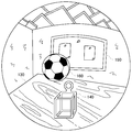
- FIG. 10 is a view for explaining a stereoscopic image of a virtual object in the virtual space generated by the image generation unit 25 when a dynamic object enters the real space.
- the ball 160 later enters the real space as a dynamic object.
- the area in which the ball 160 is photographed is determined to be an unknown depth area.
- the unknown depth processing unit 27 instructs the image generation unit 25 to display the photographed image of the ball 160 in the unknown depth region.
- the image generation unit 25 superimposes the image of the ball 160 on the rendered image of the virtual space.
- the alternative virtual object may be rendered in the unknown depth region. For example, when a dog has entered the real space, a virtual dog or another character may be rendered in the unknown depth region.
- FIG. 11 is a diagram for explaining a stereoscopic image of a virtual object in the virtual space generated by the image generation unit 25 when the user's body enters the real space.
- the virtual object to be replaced is not determined in advance for the user's hand 170 entering the real space later, so in the area where the user's hand 170 is imaged, the difference between the depth value of the captured image and the depth value of the virtual image
- the area where the absolute value of H exceeds the predetermined threshold and the hand 170 is photographed is determined to be an unknown depth area.
- the photographed image of the hand 170 is superimposed on the unknown depth region.
- the robot hand may be rendered in an unknown depth area as an alternative virtual object instead of the image of the hand-captured hand 170.
- the unknown depth region it is determined whether the unknown object collides with the object (or the corresponding virtual object) in the real space, and if it is determined that the collision occurs, some kind of interaction is generated, or It may be used as an interface.
- the interaction in the unknown depth region will be described in detail below.
- a continuous unknown depth region is cut out from the captured image, and a collision region in which the space occupied by the unknown object is approximated by a cube or a sphere is generated.
- the collision region of the unknown object is converted from the camera space to the world space, and the collision region of the unknown object is the region and contact occupied by the object in the real space, the corresponding virtual object, the user's body, and other virtual objects. It is determined by comparing depth values. Thereby, it can be determined whether the unknown object collides with the object in the real space, the corresponding virtual object, the user's body, or other virtual objects. This collision determination is performed by the depth comparison unit 22.
- the unknown depth area cut out from the captured image is taken between the frames, it can be determined whether the unknown depth area moving between the frames is of the same object. If the inter-frame difference in the unknown depth region is large, it is considered that a new unknown object has occurred rather than the same unknown object moving. Further, the moving speed of the unknown object can be estimated from the inter-frame difference of the unknown depth region, and the pre-reading of the collision determination becomes possible.
- attitude difference velocity and angular velocity
- a video transmission (video see-through) type display device has been described as an example, but an optical transmission (optical see-through) type display in which the display unit is configured with a half mirror or the like and causes the user to visually recognize the physical space in front of the eye
- the present embodiment can also be applied to the device.
- the depth information of the real space is compared with the depth information of the image of the virtual space, and the image of the virtual space is used for the region where the object of the real space is present before the virtual object. Delete and make it visible through the real space.
- the unknown depth region is determined by using the method of comparing the absolute value of the difference between the depth values described in the depth comparison unit 22 of the present embodiment with the predetermined threshold value to compare the depth information, and the unknown depth region is virtually estimated.
- the user can transparently view the dynamic object in the real space which has suddenly entered in front of the virtual object.
- the present invention can be used in image processing technology.
Landscapes
- Engineering & Computer Science (AREA)
- Multimedia (AREA)
- General Engineering & Computer Science (AREA)
- Theoretical Computer Science (AREA)
- Human Computer Interaction (AREA)
- Physics & Mathematics (AREA)
- General Physics & Mathematics (AREA)
- Signal Processing (AREA)
- Computer Graphics (AREA)
- Computer Hardware Design (AREA)
- Software Systems (AREA)
- Processing Or Creating Images (AREA)
Abstract
Selon l'invention, une partie de formation d'espace virtuel (23) utilise des informations de profondeur relatives à l'image d'un espace réel à proximité d'un utilisateur afin de détecter les positions d'objets d'intérêt dans l'espace réel, puis dispose les objets virtuels dans les positions de l'espace virtuel correspondant aux positions des objets d'intérêt détectés de façon à créer des informations représentant l'espace virtuel. Une partie de génération d'image (25) génère une image de l'espace virtuel formé par la partie de formation d'espace virtuel (23). Une partie de comparaison de profondeur (22) détermine une zone de profondeur inconnue en comparant les informations de profondeur relatives à l'image de l'espace réel avec les informations de profondeur relatives à l'image de l'espace virtuel. La partie de génération d'image (25) affiche des informations indiquant la présence d'un objet d'intérêt inconnu dans la zone de profondeur inconnue de l'image de l'espace virtuel.
Priority Applications (2)
| Application Number | Priority Date | Filing Date | Title |
|---|---|---|---|
| JP2019560037A JP6933727B2 (ja) | 2017-12-19 | 2018-09-04 | 画像処理装置、画像処理方法、およびプログラム |
| US16/764,364 US11176748B2 (en) | 2017-12-19 | 2018-09-04 | Image processing apparatus, image processing method, and program |
Applications Claiming Priority (2)
| Application Number | Priority Date | Filing Date | Title |
|---|---|---|---|
| JP2017242824 | 2017-12-19 | ||
| JP2017-242824 | 2017-12-19 |
Publications (1)
| Publication Number | Publication Date |
|---|---|
| WO2019123729A1 true WO2019123729A1 (fr) | 2019-06-27 |
Family
ID=66994540
Family Applications (1)
| Application Number | Title | Priority Date | Filing Date |
|---|---|---|---|
| PCT/JP2018/032773 Ceased WO2019123729A1 (fr) | 2017-12-19 | 2018-09-04 | Dispositif de traitement d'image, procédé de traitement d'images et programme |
Country Status (3)
| Country | Link |
|---|---|
| US (1) | US11176748B2 (fr) |
| JP (1) | JP6933727B2 (fr) |
| WO (1) | WO2019123729A1 (fr) |
Cited By (5)
| Publication number | Priority date | Publication date | Assignee | Title |
|---|---|---|---|---|
| JP2023518908A (ja) * | 2020-03-30 | 2023-05-08 | ユーム.コム リミテッド | ラベル付き入力を使用してメッシュ精度を向上させる技法 |
| JP2023520765A (ja) * | 2020-03-24 | 2023-05-19 | マジック リープ, インコーポレイテッド | 仮想および拡張現実のためのシステムおよび方法 |
| JP2023534888A (ja) * | 2020-05-22 | 2023-08-15 | グーグル エルエルシー | 実世界画像において拡張現実オブジェクトを組み合わせるための方法および装置 |
| JP2025113066A (ja) * | 2024-01-30 | 2025-08-01 | 任天堂株式会社 | 情報処理プログラム、情報処理システム、情報処理装置、および、情報処理方法 |
| JP2025134062A (ja) * | 2020-02-07 | 2025-09-11 | 株式会社ドワンゴ | 仮想空間制御システム、仮想空間制御方法、およびプログラム |
Families Citing this family (17)
| Publication number | Priority date | Publication date | Assignee | Title |
|---|---|---|---|---|
| EP3577896A4 (fr) | 2017-02-03 | 2020-11-25 | Warner Bros. Entertainment Inc. | Rendu de vidéo étendue en réalité virtuelle |
| US11120632B2 (en) * | 2018-10-16 | 2021-09-14 | Sony Interactive Entertainment Inc. | Image generating apparatus, image generating system, image generating method, and program |
| JP6895128B2 (ja) * | 2018-11-09 | 2021-06-30 | オムロン株式会社 | ロボット制御装置、シミュレーション方法、及びシミュレーションプログラム |
| JP7527778B2 (ja) * | 2019-12-05 | 2024-08-05 | キヤノン株式会社 | 電子機器、電子機器の制御方法、プログラム、記憶媒体 |
| US20230214004A1 (en) * | 2020-05-21 | 2023-07-06 | Sony Group Corporation | Information processing apparatus, information processing method, and information processing program |
| US11210844B1 (en) | 2021-04-13 | 2021-12-28 | Dapper Labs Inc. | System and method for creating, managing, and displaying 3D digital collectibles |
| US11099709B1 (en) | 2021-04-13 | 2021-08-24 | Dapper Labs Inc. | System and method for creating, managing, and displaying an interactive display for 3D digital collectibles |
| USD991271S1 (en) | 2021-04-30 | 2023-07-04 | Dapper Labs, Inc. | Display screen with an animated graphical user interface |
| US11227010B1 (en) | 2021-05-03 | 2022-01-18 | Dapper Labs Inc. | System and method for creating, managing, and displaying user owned collections of 3D digital collectibles |
| US11170582B1 (en) | 2021-05-04 | 2021-11-09 | Dapper Labs Inc. | System and method for creating, managing, and displaying limited edition, serialized 3D digital collectibles with visual indicators of rarity classifications |
| US11533467B2 (en) | 2021-05-04 | 2022-12-20 | Dapper Labs, Inc. | System and method for creating, managing, and displaying 3D digital collectibles with overlay display elements and surrounding structure display elements |
| CN115423915A (zh) * | 2021-05-31 | 2022-12-02 | 北京字跳网络技术有限公司 | 一种图像渲染方法及装置 |
| CN115423913B (zh) | 2021-05-31 | 2026-01-13 | 北京字跳网络技术有限公司 | 一种粒子渲染方法及装置 |
| US11890534B2 (en) | 2021-09-28 | 2024-02-06 | Sony Group Corporation | Method for predefining a virtual entryway at a virtual boundary of an XR space |
| US12134031B2 (en) * | 2021-09-28 | 2024-11-05 | Sony Group Corporation | Method for predefining in an XR space an entryway corresponding to a real entryway |
| US12518307B1 (en) | 2022-09-07 | 2026-01-06 | Meta Platforms Technologies, Llc | Human body scanning for size recommendation |
| US20240119690A1 (en) * | 2022-10-05 | 2024-04-11 | Meta Platforms Technologies, Llc | Stylizing representations in immersive reality applications |
Citations (3)
| Publication number | Priority date | Publication date | Assignee | Title |
|---|---|---|---|---|
| JP2012155655A (ja) * | 2011-01-28 | 2012-08-16 | Sony Corp | 情報処理装置、報知方法及びプログラム |
| US20150243079A1 (en) * | 2014-02-27 | 2015-08-27 | Lg Electronics Inc. | Head mounted display providing closed-view and method of controlling therefor |
| JP2016004493A (ja) * | 2014-06-18 | 2016-01-12 | キヤノン株式会社 | 画像処理装置およびその制御方法 |
Family Cites Families (3)
| Publication number | Priority date | Publication date | Assignee | Title |
|---|---|---|---|---|
| JP2004537082A (ja) * | 2001-01-26 | 2004-12-09 | ザクセル システムズ インコーポレイテッド | 仮想現実環境における実時間バーチャル・ビューポイント |
| KR102077108B1 (ko) * | 2013-09-13 | 2020-02-14 | 한국전자통신연구원 | 콘텐츠 체험 서비스 제공 장치 및 그 방법 |
| GB2551396B (en) * | 2016-06-17 | 2018-10-10 | Imagination Tech Ltd | Augmented reality occlusion |
-
2018
- 2018-09-04 WO PCT/JP2018/032773 patent/WO2019123729A1/fr not_active Ceased
- 2018-09-04 US US16/764,364 patent/US11176748B2/en active Active
- 2018-09-04 JP JP2019560037A patent/JP6933727B2/ja active Active
Patent Citations (3)
| Publication number | Priority date | Publication date | Assignee | Title |
|---|---|---|---|---|
| JP2012155655A (ja) * | 2011-01-28 | 2012-08-16 | Sony Corp | 情報処理装置、報知方法及びプログラム |
| US20150243079A1 (en) * | 2014-02-27 | 2015-08-27 | Lg Electronics Inc. | Head mounted display providing closed-view and method of controlling therefor |
| JP2016004493A (ja) * | 2014-06-18 | 2016-01-12 | キヤノン株式会社 | 画像処理装置およびその制御方法 |
Cited By (9)
| Publication number | Priority date | Publication date | Assignee | Title |
|---|---|---|---|---|
| JP2025134062A (ja) * | 2020-02-07 | 2025-09-11 | 株式会社ドワンゴ | 仮想空間制御システム、仮想空間制御方法、およびプログラム |
| JP2023520765A (ja) * | 2020-03-24 | 2023-05-19 | マジック リープ, インコーポレイテッド | 仮想および拡張現実のためのシステムおよび方法 |
| JP7560568B2 (ja) | 2020-03-24 | 2024-10-02 | マジック リープ, インコーポレイテッド | 仮想および拡張現実のためのシステムおよび方法 |
| US12112574B2 (en) | 2020-03-24 | 2024-10-08 | Magic Leap, Inc. | Systems and methods for virtual and augmented reality |
| JP2023518908A (ja) * | 2020-03-30 | 2023-05-08 | ユーム.コム リミテッド | ラベル付き入力を使用してメッシュ精度を向上させる技法 |
| JP2023534888A (ja) * | 2020-05-22 | 2023-08-15 | グーグル エルエルシー | 実世界画像において拡張現実オブジェクトを組み合わせるための方法および装置 |
| JP7699611B2 (ja) | 2020-05-22 | 2025-06-27 | グーグル エルエルシー | 実世界画像において拡張現実オブジェクトを組み合わせるための方法および装置 |
| JP2025113066A (ja) * | 2024-01-30 | 2025-08-01 | 任天堂株式会社 | 情報処理プログラム、情報処理システム、情報処理装置、および、情報処理方法 |
| JP7818024B2 (ja) | 2024-01-30 | 2026-02-19 | 任天堂株式会社 | 情報処理プログラム、情報処理システム、情報処理装置、および、情報処理方法 |
Also Published As
| Publication number | Publication date |
|---|---|
| US11176748B2 (en) | 2021-11-16 |
| JPWO2019123729A1 (ja) | 2020-12-17 |
| JP6933727B2 (ja) | 2021-09-08 |
| US20200279438A1 (en) | 2020-09-03 |
Similar Documents
| Publication | Publication Date | Title |
|---|---|---|
| JP6933727B2 (ja) | 画像処理装置、画像処理方法、およびプログラム | |
| JP6682624B2 (ja) | 画像処理装置 | |
| KR102060453B1 (ko) | 화상 표시 시스템, 화상 표시 시스템의 제어방법, 화상 전송 시스템 및 헤드 마운트 디스플레이 | |
| JP7423683B2 (ja) | 画像表示システム | |
| CN105981076B (zh) | 合成增强现实环境的构造 | |
| JP5996814B1 (ja) | 仮想空間の画像をヘッドマウントディスプレイに提供する方法及びプログラム | |
| CN118938467A (zh) | 具有直通成像的头戴式显示器 | |
| US20160343166A1 (en) | Image-capturing system for combining subject and three-dimensional virtual space in real time | |
| JP6039594B2 (ja) | 情報処理装置および情報処理方法 | |
| CA2951058A1 (fr) | Plate-forme a realite virtuelle autostereoscopique | |
| JP2015084002A (ja) | ミラーディスプレイシステム、及び、その映像表示方法 | |
| US12368836B2 (en) | Image display system and image display method | |
| CN108830944A (zh) | 光学透视式三维近眼显示系统及显示方法 | |
| WO2017191703A1 (fr) | Dispositif de traitement d'images | |
| WO2018084087A1 (fr) | Système d'affichage d'images, dispositif d'affichage d'images, procédé de commande associé, et programme | |
| US20190295324A1 (en) | Optimized content sharing interaction using a mixed reality environment | |
| JP6726016B2 (ja) | 情報処理装置、情報処理方法 | |
| CN108205823A (zh) | Mr全息真空体验店和体验方法 | |
| JP6739539B2 (ja) | 情報処理装置 | |
| JP2017142769A (ja) | 仮想空間の画像をヘッドマウントディスプレイに提供する方法及びプログラム | |
| WO2018173206A1 (fr) | Dispositif de traitement d'informations | |
| JP2001283258A (ja) | 仮想空間疑似体験システム |
Legal Events
| Date | Code | Title | Description |
|---|---|---|---|
| 121 | Ep: the epo has been informed by wipo that ep was designated in this application |
Ref document number: 18890721 Country of ref document: EP Kind code of ref document: A1 |
|
| ENP | Entry into the national phase |
Ref document number: 2019560037 Country of ref document: JP Kind code of ref document: A |
|
| NENP | Non-entry into the national phase |
Ref country code: DE |
|
| 122 | Ep: pct application non-entry in european phase |
Ref document number: 18890721 Country of ref document: EP Kind code of ref document: A1 |