WO2019123787A1 - Axial flow compressor - Google Patents
Axial flow compressor Download PDFInfo
- Publication number
- WO2019123787A1 WO2019123787A1 PCT/JP2018/037724 JP2018037724W WO2019123787A1 WO 2019123787 A1 WO2019123787 A1 WO 2019123787A1 JP 2018037724 W JP2018037724 W JP 2018037724W WO 2019123787 A1 WO2019123787 A1 WO 2019123787A1
- Authority
- WO
- WIPO (PCT)
- Prior art keywords
- casing
- plasma
- blade
- plasma actuator
- variable
- Prior art date
- Legal status (The legal status is an assumption and is not a legal conclusion. Google has not performed a legal analysis and makes no representation as to the accuracy of the status listed.)
- Ceased
Links
Images



Classifications
-
- F—MECHANICAL ENGINEERING; LIGHTING; HEATING; WEAPONS; BLASTING
- F01—MACHINES OR ENGINES IN GENERAL; ENGINE PLANTS IN GENERAL; STEAM ENGINES
- F01D—NON-POSITIVE DISPLACEMENT MACHINES OR ENGINES, e.g. STEAM TURBINES
- F01D11/00—Preventing or minimising internal leakage of working-fluid, e.g. between stages
- F01D11/08—Preventing or minimising internal leakage of working-fluid, e.g. between stages for sealing space between rotor blade tips and stator
- F01D11/10—Preventing or minimising internal leakage of working-fluid, e.g. between stages for sealing space between rotor blade tips and stator using sealing fluid, e.g. steam
-
- F—MECHANICAL ENGINEERING; LIGHTING; HEATING; WEAPONS; BLASTING
- F04—POSITIVE - DISPLACEMENT MACHINES FOR LIQUIDS; PUMPS FOR LIQUIDS OR ELASTIC FLUIDS
- F04D—NON-POSITIVE-DISPLACEMENT PUMPS
- F04D29/00—Details, component parts, or accessories
- F04D29/40—Casings; Connections of working fluid
- F04D29/52—Casings; Connections of working fluid for axial pumps
- F04D29/54—Fluid-guiding means, e.g. diffusers
- F04D29/56—Fluid-guiding means, e.g. diffusers adjustable
- F04D29/563—Fluid-guiding means, e.g. diffusers adjustable specially adapted for elastic fluid pumps
-
- F—MECHANICAL ENGINEERING; LIGHTING; HEATING; WEAPONS; BLASTING
- F01—MACHINES OR ENGINES IN GENERAL; ENGINE PLANTS IN GENERAL; STEAM ENGINES
- F01D—NON-POSITIVE DISPLACEMENT MACHINES OR ENGINES, e.g. STEAM TURBINES
- F01D11/00—Preventing or minimising internal leakage of working-fluid, e.g. between stages
- F01D11/005—Sealing means between non relatively rotating elements
-
- F—MECHANICAL ENGINEERING; LIGHTING; HEATING; WEAPONS; BLASTING
- F01—MACHINES OR ENGINES IN GENERAL; ENGINE PLANTS IN GENERAL; STEAM ENGINES
- F01D—NON-POSITIVE DISPLACEMENT MACHINES OR ENGINES, e.g. STEAM TURBINES
- F01D17/00—Regulating or controlling by varying flow
- F01D17/10—Final actuators
- F01D17/12—Final actuators arranged in stator parts
- F01D17/14—Final actuators arranged in stator parts varying effective cross-sectional area of nozzles or guide conduits
- F01D17/16—Final actuators arranged in stator parts varying effective cross-sectional area of nozzles or guide conduits by means of nozzle vanes
- F01D17/162—Final actuators arranged in stator parts varying effective cross-sectional area of nozzles or guide conduits by means of nozzle vanes for axial flow, i.e. the vanes turning around axes which are essentially perpendicular to the rotor centre line
-
- F—MECHANICAL ENGINEERING; LIGHTING; HEATING; WEAPONS; BLASTING
- F02—COMBUSTION ENGINES; HOT-GAS OR COMBUSTION-PRODUCT ENGINE PLANTS
- F02C—GAS-TURBINE PLANTS; AIR INTAKES FOR JET-PROPULSION PLANTS; CONTROLLING FUEL SUPPLY IN AIR-BREATHING JET-PROPULSION PLANTS
- F02C7/00—Features, components parts, details or accessories, not provided for in, or of interest apart form groups F02C1/00 - F02C6/00; Air intakes for jet-propulsion plants
- F02C7/04—Air intakes for gas-turbine plants or jet-propulsion plants
- F02C7/042—Air intakes for gas-turbine plants or jet-propulsion plants having variable geometry
-
- F—MECHANICAL ENGINEERING; LIGHTING; HEATING; WEAPONS; BLASTING
- F02—COMBUSTION ENGINES; HOT-GAS OR COMBUSTION-PRODUCT ENGINE PLANTS
- F02C—GAS-TURBINE PLANTS; AIR INTAKES FOR JET-PROPULSION PLANTS; CONTROLLING FUEL SUPPLY IN AIR-BREATHING JET-PROPULSION PLANTS
- F02C9/00—Controlling gas-turbine plants; Controlling fuel supply in air- breathing jet-propulsion plants
- F02C9/16—Control of working fluid flow
- F02C9/20—Control of working fluid flow by throttling; by adjusting vanes
-
- F—MECHANICAL ENGINEERING; LIGHTING; HEATING; WEAPONS; BLASTING
- F04—POSITIVE - DISPLACEMENT MACHINES FOR LIQUIDS; PUMPS FOR LIQUIDS OR ELASTIC FLUIDS
- F04D—NON-POSITIVE-DISPLACEMENT PUMPS
- F04D29/00—Details, component parts, or accessories
- F04D29/08—Sealings
- F04D29/16—Sealings between pressure and suction sides
- F04D29/161—Sealings between pressure and suction sides especially adapted for elastic fluid pumps
- F04D29/164—Sealings between pressure and suction sides especially adapted for elastic fluid pumps of an axial flow wheel
-
- F—MECHANICAL ENGINEERING; LIGHTING; HEATING; WEAPONS; BLASTING
- F04—POSITIVE - DISPLACEMENT MACHINES FOR LIQUIDS; PUMPS FOR LIQUIDS OR ELASTIC FLUIDS
- F04D—NON-POSITIVE-DISPLACEMENT PUMPS
- F04D29/00—Details, component parts, or accessories
- F04D29/66—Combating cavitation, whirls, noise, vibration or the like; Balancing
- F04D29/68—Combating cavitation, whirls, noise, vibration or the like; Balancing by influencing boundary layers
- F04D29/681—Combating cavitation, whirls, noise, vibration or the like; Balancing by influencing boundary layers especially adapted for elastic fluid pumps
- F04D29/687—Plasma actuators therefore
-
- F—MECHANICAL ENGINEERING; LIGHTING; HEATING; WEAPONS; BLASTING
- F23—COMBUSTION APPARATUS; COMBUSTION PROCESSES
- F23R—GENERATING COMBUSTION PRODUCTS OF HIGH PRESSURE OR HIGH VELOCITY, e.g. GAS-TURBINE COMBUSTION CHAMBERS
- F23R3/00—Continuous combustion chambers using liquid or gaseous fuel
- F23R3/02—Continuous combustion chambers using liquid or gaseous fuel characterised by the air-flow or gas-flow configuration
- F23R3/04—Air inlet arrangements
-
- F—MECHANICAL ENGINEERING; LIGHTING; HEATING; WEAPONS; BLASTING
- F05—INDEXING SCHEMES RELATING TO ENGINES OR PUMPS IN VARIOUS SUBCLASSES OF CLASSES F01-F04
- F05D—INDEXING SCHEME FOR ASPECTS RELATING TO NON-POSITIVE-DISPLACEMENT MACHINES OR ENGINES, GAS-TURBINES OR JET-PROPULSION PLANTS
- F05D2240/00—Components
- F05D2240/10—Stators
- F05D2240/12—Fluid guiding means, e.g. vanes
-
- F—MECHANICAL ENGINEERING; LIGHTING; HEATING; WEAPONS; BLASTING
- F05—INDEXING SCHEMES RELATING TO ENGINES OR PUMPS IN VARIOUS SUBCLASSES OF CLASSES F01-F04
- F05D—INDEXING SCHEME FOR ASPECTS RELATING TO NON-POSITIVE-DISPLACEMENT MACHINES OR ENGINES, GAS-TURBINES OR JET-PROPULSION PLANTS
- F05D2240/00—Components
- F05D2240/55—Seals
-
- F—MECHANICAL ENGINEERING; LIGHTING; HEATING; WEAPONS; BLASTING
- F05—INDEXING SCHEMES RELATING TO ENGINES OR PUMPS IN VARIOUS SUBCLASSES OF CLASSES F01-F04
- F05D—INDEXING SCHEME FOR ASPECTS RELATING TO NON-POSITIVE-DISPLACEMENT MACHINES OR ENGINES, GAS-TURBINES OR JET-PROPULSION PLANTS
- F05D2270/00—Control
- F05D2270/01—Purpose of the control system
- F05D2270/17—Purpose of the control system to control boundary layer
- F05D2270/172—Purpose of the control system to control boundary layer by a plasma generator, e.g. control of ignition
Definitions
- variable stator vane VSV: Variable Stator Vane
- the angle of the variable stator vanes is set to an optimal value in accordance with various conditions such as the operating condition of the engine and the temperature of the working fluid. For example, in a situation such as start-up where the rotational speed of a moving blade provided downstream of the variable stator vane is significantly lower than the design rotational speed and stalling is likely to occur in the moving blade, It is controlled to narrow the opening degree. As a result, the absolute velocity of the working fluid is increased to suppress an excessive increase in attack angle, thereby avoiding the occurrence and enlargement of a stall such as a rotating stall (see Patent Document 1).
- the second electrode 45 is located downstream of the first electrode 44 on the downstream side of the annular flow channel 21 on the back surface 43 b of the insulating substrate 43.
- the second electrode 45 is connected to the common of the high frequency power supply 48 (in other words, the common (ground) of the circuit constituting the plasma actuator 40).
- the clearance 32 is formed between the wing body 16 of the variable stationary vane 12 and the inner peripheral surface 7 a of the casing 7.
- a portion of the working fluid leaks from the ventral side 16 e (pressure side) of the wing 16 to the back side 16 f (negative side) of the wing via the clearance 32.
- Vortices (swirls) 61 generated with the leaked flow 60 increase the loss in the variable stator vanes 12.
Landscapes
- Engineering & Computer Science (AREA)
- Mechanical Engineering (AREA)
- General Engineering & Computer Science (AREA)
- Chemical & Material Sciences (AREA)
- Combustion & Propulsion (AREA)
- Physics & Mathematics (AREA)
- Geometry (AREA)
- Fluid Mechanics (AREA)
- Plasma & Fusion (AREA)
- Structures Of Non-Positive Displacement Pumps (AREA)
- Plasma Technology (AREA)
Abstract
Description
本開示は、ガスタービンエンジンに搭載される軸流圧縮機に関する。 The present disclosure relates to an axial compressor mounted on a gas turbine engine.
軸流機械の一種である軸流圧縮機は、回転体(ディスク、ドラム)の翼軸に沿って交互に配列した静翼列及び動翼列を備えている。静翼列の各静翼は作動流体の流路を形成するケーシングに固定されている。一方、動翼列の各動翼は回転体に固定され、回転体と共に回転する。 An axial-flow compressor, which is a type of axial-flow machine, includes a stationary blade row and a moving blade row alternately arranged along the blade axis of a rotating body (disk, drum). Each of the vanes of the vane array is fixed to a casing forming a flow path of the working fluid. On the other hand, each moving blade of the moving blade row is fixed to the rotating body and rotates together with the rotating body.
可変静翼(VSV: Variable Stator Vane)は静翼列の各静翼を揺動可能に設けたものである。可変静翼の角度は、エンジンの稼働状況や作動流体の温度などの諸条件に応じて最適な値に設定される。例えば、可変静翼の後段に設けられた動翼の回転数が設計回転数よりも著しく低く、当該動翼でストールが発生しやすい起動時のような状況において、可変静翼は静翼列の開度を絞るように制御される。これにより作動流体の絶対速度を高めて迎角の過剰な増加を抑え、旋回失速等のストールの発生や拡大を回避している(特許文献1参照)。 A variable stator vane (VSV: Variable Stator Vane) is provided with each vane of the vane row so as to be able to swing. The angle of the variable stator vanes is set to an optimal value in accordance with various conditions such as the operating condition of the engine and the temperature of the working fluid. For example, in a situation such as start-up where the rotational speed of a moving blade provided downstream of the variable stator vane is significantly lower than the design rotational speed and stalling is likely to occur in the moving blade, It is controlled to narrow the opening degree. As a result, the absolute velocity of the working fluid is increased to suppress an excessive increase in attack angle, thereby avoiding the occurrence and enlargement of a stall such as a rotating stall (see Patent Document 1).
ところで、軸流圧縮機のケーシングの表面近傍における作動流体の流れを制御する装置として、近年、プラズマアクチュエータが注目されている(特許文献2~6参照)。
By the way, in recent years, a plasma actuator has attracted attention as a device for controlling the flow of the working fluid in the vicinity of the surface of the casing of the axial flow compressor (see
可変静翼の揺動を可能にするため、可変静翼の翼体とケーシングとの間にはクリアランスが形成される。従って、作動流体の一部は、このクリアランスを介して翼体の腹側(圧力面側)から翼体の背側(負圧面側)に漏れてしまう。この漏れ流れに伴って発生する渦(スワール)は、可変静翼における損失を増大させる。 A clearance is formed between the vanes of the variable stator vanes and the casing in order to allow rocking of the variable stator vanes. Therefore, part of the working fluid leaks from the ventral side (pressure side) of the wing to the dorsal side (negative pressure side) of the wing via this clearance. Vortices (swirls) generated with this leak flow increase the loss in the variable stator vanes.
そこで本開示は、可変静翼を備える軸流圧縮機において、可変静翼の翼体とケーシングの間のクリアランスに起因する損失を抑制することを目的とする。 Therefore, the present disclosure is directed to, in an axial flow compressor including a variable stator vane, suppressing loss due to the clearance between the vane body of the variable stator vane and the casing.
本開示の一態様は軸流圧縮機であって、筒状のケーシングと、揺動中心としての翼軸を有し、静翼或いは入口案内翼として前記ケーシング内に設けられ、前記ケーシングの周方向に配列する可変静翼と、前記ケーシング内において前記可変静翼の後縁側に設けられ、前記ケーシングの周方向に配列する動翼と、前記可変静翼と前記ケーシングの前記内周面との間のクリアランスと交差し、且つ、前記ケーシングの周方向に向けて環状に分布するプラズマを生成し、前記ケーシングの内周面に取り付けられるプラズマアクチュエータと、を備えることを要旨とする。 One aspect of the present disclosure is an axial flow compressor, which has a cylindrical casing and a blade shaft as a rocking center, and is provided in the casing as a stationary blade or an inlet guide blade, and the circumferential direction of the casing Between the variable stator vanes arranged in the casing, the rotor blade provided on the rear edge side of the variable stator vanes in the casing and arranged in the circumferential direction of the casing, the variable stator vanes and the inner circumferential surface of the casing And a plasma actuator which is generated in an annular distribution in the circumferential direction of the casing and is attached to the inner circumferential surface of the casing.
前記プラズマアクチュエータは、対応する可変静翼に合わせて複数のセグメントに分割されてもよい。 The plasma actuator may be divided into a plurality of segments according to the corresponding variable stator vanes.
前記プラズマアクチュエータは、前記ケーシングの前記内周面において前記可変静翼の翼軸の列と前記動翼の列との間に取り付けられてもよい。 The plasma actuator may be mounted between the row of blade axes of the variable stator vanes and the row of moving blades on the inner circumferential surface of the casing.
前記プラズマアクチュエータは、前記ケーシングの軸方向において前記翼軸と全閉状態の前記可変静翼の後縁との間の第1領域に位置してもよい。 The plasma actuator may be located in a first region in an axial direction of the casing between the blade shaft and a trailing edge of the variable stator vane in a fully closed state.
前記プラズマアクチュエータは、更に、前記ケーシングの軸方向において全閉状態の前記可変静翼の後縁と全開状態の前記可変静翼の後縁との間の第2領域に位置してもよい。 The plasma actuator may be further located in a second region between the trailing edge of the variable stator vane in the fully closed state and the trailing edge of the variable vane in the fully open state in the axial direction of the casing.
前記プラズマアクチュエータによる前記第2領域におけるプラズマの発生は、前記可変静翼の開度に応じて制御されてもよい。 The generation of plasma in the second region by the plasma actuator may be controlled in accordance with the opening degree of the variable stator blade.
前記プラズマアクチュエータの各セグメントは、対応する可変静翼のコード方向と交差する方向に延伸してもよい。 Each segment of the plasma actuator may extend in a direction that intersects the code direction of the corresponding variable stator vane.
前記プラズマアクチュエータは、前記可変静翼が半開状態にある時にプラズマを発生してもよい。 The plasma actuator may generate plasma when the variable stator vane is in a half open state.
前記プラズマアクチュエータは、前記動翼によるストールの予兆が検知されたときにプラズマを発生してもよい。 The plasma actuator may generate plasma when a sign of a stall due to the blades is detected.
本開示によれば、可変静翼を備える軸流圧縮機において、可変静翼の翼体とケーシングの間のクリアランスに起因する損失を抑制することができる。 According to the present disclosure, in an axial flow compressor provided with variable stator vanes, it is possible to suppress loss due to the clearance between the vane bodies of the variable stator vanes and the casing.
以下、本開示の実施形態に係る軸流圧縮機について添付図面に基づいて説明する。本実施形態に係る軸流圧縮機はガスタービンエンジンに搭載される。ガスタービンエンジンは、例えば、ターボジェットエンジン、ターボファンエンジン、ターボプロップエンジンなどである。また、ガスタービンエンジンは航空機用のものに限られず、例えば、舶用や発電用のガスタービンエンジンにも適用可能である。以下、説明の便宜上、軸流圧縮機を搭載するガスタービンエンジンの一例としてターボファンエンジンを挙げる。また、ターボファンエンジンを単にエンジンと称し、軸流圧縮機を単に圧縮機と称するものとする。 Hereinafter, an axial flow compressor according to an embodiment of the present disclosure will be described based on the attached drawings. The axial flow compressor according to the present embodiment is mounted on a gas turbine engine. The gas turbine engine is, for example, a turbo jet engine, a turbo fan engine, or a turbo prop engine. In addition, the gas turbine engine is not limited to that for aircraft, and can also be applied to, for example, marine or power generation gas turbine engines. Hereinafter, for convenience of explanation, a turbofan engine will be taken as an example of a gas turbine engine equipped with an axial flow compressor. Also, a turbofan engine is simply referred to as an engine, and an axial compressor is simply referred to as a compressor.
(第1実施形態)
図1は、本実施形態の軸流圧縮機を搭載したエンジン10の構成図である。この図に示すように、エンジン10は、ファン2と、圧縮機3と、燃焼室4と、タービン5とを備えている。これらは軸1を中心として筒状に形成されたケーシング7内に収容され、作動流体(即ち空気や燃焼ガス)の主流において上流側(図1における左側)から下流側(図1における右側)に配列している。なお、エンジン10は圧縮機3とタービン5を1組備えた一軸式のエンジンでもよく、圧力に応じた圧縮機3とタービン5を複数組備えた多軸式のエンジンでもよい。
First Embodiment
FIG. 1 is a block diagram of an
ファン2は、軸1を中心として放射状に設けられたファン動翼11を備え、作動流体である空気をエンジン10の外部からケーシング7内に導入し、一部の空気を圧縮機3へ供給する。残りの空気はファン2を通過後、大気に排出する。
The
圧縮機3は、ケーシング7内に軸1を中心として放射状に設けられた静翼12及び動翼13を備え、エンジン入口から供給された空気を圧縮し、燃焼室4へ供給する。静翼12は、圧縮機3内で揺動可能に設けられた所謂可変静翼である。以下、静翼12を可変静翼12と称する。可変静翼12及び動翼13は、何れもケーシング7の周方向に配列している。可変静翼12と動翼13の各列は、軸1に沿って交互に設置されている。この圧縮機3の詳細については後述する。
The compressor 3 includes a
燃焼室4には、燃料の供給系統(図示せず)が接続している。燃焼室4は点火装置(図示せず)を備え、圧縮機3によって圧縮された空気と燃料とを混合し、その混合ガスを燃焼する。生成された燃焼ガスはタービン5に排出される。
A fuel supply system (not shown) is connected to the
タービン5は、ケーシング7内に設けられ、軸1を中心として放射状に設けられたタービン静翼14及びタービン動翼15を備える。タービン静翼14及びタービン動翼15は、何れもケーシング7の周方向に配列している。タービン静翼14とタービン動翼15の各列は、軸1に沿って交互に設置されている。
The
燃焼室4から排出された燃焼ガスは、タービン静翼14を通過する際に膨張しながら加速し、タービン動翼15に向けて噴出する。噴出した燃焼ガスはタービン動翼15を回転させる。このような過程によって、燃焼ガスの熱エネルギーが回転エネルギーに変換され、燃焼ガスはダクト6を介してエンジン10から排出される。タービン5によって変換された回転エネルギーは、ロータ8を介してファン2及び圧縮機3に伝達され、ファン2のファン動翼11及び圧縮機3の動翼13が軸1を回転中心として回転する。
The combustion gas discharged from the
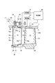
図2は、本実施形態に係る圧縮機3の部分拡大図である。この図に示すように、可変静翼12は翼体16と、可変静翼12の揺動中心としての翼軸(回転軸)17、18とを有する。翼体16は、翼軸17、18を介してケーシング7とプラットフォーム19に揺動可能に支持されている。なお、圧縮機3において、ケーシング7は作動流体が流れる環状流路21の外壁(即ちシュラウド)として機能する。また、可変静翼12のプラットフォーム19と動翼13のプラットフォーム20は、環状流路21の内壁として機能する。
FIG. 2 is a partially enlarged view of the compressor 3 according to the present embodiment. As shown in this figure, the variable
翼軸17は翼体16の先端(チップ)16a側に設けられている。翼軸17は、シャフト22と、ボタン23とを有する。シャフト22は断面円形の棒状体であり、その中心軸は可変静翼12(翼体16)の揺動中心軸24に一致している。シャフト22は、ケーシング7に形成された支持孔25を貫通している。
The
ボタン23はシャフト22と翼体16との間に設けられ、シャフト22と翼体16を連結している。ボタン23はケーシング7の厚さよりも薄い円板であり、翼体16の一部と一体化されることにより翼体16を支持している。ボタン23は、ケーシング7の支持孔25を含む凹部7bに埋設されており、環状流路21に露出する表面23aを有する。この表面23aは、ケーシング7の内周面7aと略同じ高さに位置し、当該表面23aに対向する翼体16の先端16aの一部と一体化している。
The
揺動中心軸24(換言すれば、翼軸17の中心軸)は、翼体16の翼弦方向において、翼体16の中央よりも前縁側に位置している。また、ボタン23の半径は、揺動中心軸24から翼体16の前縁16cまでの距離以上の値に設定されている。上述の通り、ボタン23の表面23aは、当該表面23aに対向する翼体16の一部と一体化している。従って、翼体16の前縁16cは、図2に示すように、ボタン23の表面23a上に位置してもよく、前縁16c側にはクリアランス(隙間)は形成されなくてもよい。
The swinging central shaft 24 (in other words, the central axis of the blade shaft 17) is located on the leading edge side of the center of the
翼軸18は、翼体16の基端(ハブ)16b側に設けられ翼軸17と同様の構造を有する。ただし、翼軸18のボタン26は、プラットフォーム19に埋設されているものの、シャフト27はプラットフォーム19を貫通していなくてもよい。
The
シャフト22は駆動機構28によって所定の角度範囲で回転する。駆動機構28は、例えば図2に示すように、アーム29、駆動リング30及び駆動部(モータ)31によって構成される。
The
シャフト22は、アーム29を介して、ケーシング7の外側に設けられた駆動リング30に連結している。アーム29はシャフト22に固定され、且つ、駆動リング30に揺動可能に連結している。駆動リング30はケーシング7の外側で、ケーシング7の周方向に延伸する環状部材である。
The
駆動リング30は、駆動部31によってケーシング7の周方向に回転する。駆動リング30が回転すると、アーム29がシャフト22を中心に回転する。この回転に伴って、シャフト22が回転し、その結果、翼体16が環状流路21内で揺動中心軸24を中心に回転(揺動)する。なお、所望の角度範囲でシャフト22を回転(揺動)させる機能を持つ限り、駆動機構28の構成は上述のものに限られない。
The
翼体16の後縁16dは、ボタン23よりも環状流路21の下流側に(即ち、動翼13に向けて)延びている。一方、可変静翼12はケーシング7に揺動可能に支持されている。従って、翼体16がケーシング7の内周面7aと干渉しないように、両者の間にはクリアランス32が形成されている。具体的には、翼体16の先端16aにおいてケーシング7の内周面7aを対向する部分が、当該内周面7aから離間しており、内周面7aとの間にクリアランス32を形成する。
The trailing
動翼13は、可変静翼12の後縁16d側(換言すれば、環状流路21において可変静翼12の列よりも下流側)に設けられている。動翼13は、翼体33と、翼体33を支持するプラットフォーム20とを有する。プラットフォーム20は、可変静翼12のプラットフォーム19と略同一面に位置し、シャンク及びダブテールを介してロータ8に支持されている(図1参照)。或いは、動翼13は、ロータ8と一体化していてもよい(所謂ブリスク)。動翼13は、ロータ8と共に軸1を中心として回転する。
The moving
なお、可変静翼12の段数は、圧縮機3の仕様に応じて適宜設定される。また、可変静翼12は、圧縮機3の最前列に設けられてもよい。この場合、可変静翼12は入口案内翼として機能する。
The number of stages of the
以下、本開示の第1実施形態に係るプラズマアクチュエータについて説明する。
圧縮機3は、第1実施形態に係るプラズマアクチュエータ40を備える。プラズマアクチュエータ40は、ジェット41を誘起するプラズマ42を発生する。プラズマアクチュエータ40は、ケーシング7の内周面7aに取り付けられ、環状を成すようにケーシング7の周方向に延伸している。例えば、プラズマアクチュエータ40は、可変静翼12の翼軸17の列17rと動翼13の列13rとの間に位置する(図4参照)。換言すれば、プラズマアクチュエータ40は、ケーシング7の周方向に延伸する環状領域(帯状領域)52内に位置する(図4参照)。環状領域52は、翼軸17におけるボタン23の最下流部23bと動翼13(翼体33)の前縁33aとに接している。なお、ある領域内にプラズマアクチュエータ40が位置するとは、少なくともプラズマ42がその領域内に位置することを意味する。従って、後述の電極や絶縁基板などの物理的構成の全てがその領域内に位置していてもよい。
Hereinafter, a plasma actuator according to a first embodiment of the present disclosure will be described.
The compressor 3 includes a
プラズマアクチュエータ40は、ケーシング7の内周面7aに形成された溝部7cに埋設されてもよい。この場合、可変静翼12の翼体16との物理的な干渉を回避できる。
The
なお、プラズマアクチュエータ40は、ケーシング7の周方向において複数のセグメントに分割されていてもよい。例えば、プラズマアクチュエータ40は、対応する可変静翼12に合わせて複数のセグメントに分割されていてもよい。さらに、各セグメントは所定の間隔で互いに離間していてもよい。プラズマアクチュエータ40を複数のセグメントに分割することによって、セグメント毎に、或いは所定の数のセグメントのグループ毎に電源部47等の電気回路を接続できる。従って、複数のセグメントのうちの一部が故障した状態でも、プラズマアクチュエータ40全体の動作に支障がない限り、プラズマアクチュエータ40の動作を継続させることができる。
The
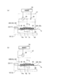
図3(a)及び図3(b)は、本実施形態に係るプラズマアクチュエータ40の構成図であり、図3(a)は三電極型のプラズマアクチュエータ40Aを用いた場合の図、図3(b)は二電極型のプラズマアクチュエータ40Bを用いた場合の図である。図3(a)に示すように、三電極型のプラズマアクチュエータ40Aは、絶縁基板(絶縁層)43と、第1電極44と、第2電極45と、第3電極46とを含む。
3 (a) and 3 (b) are block diagrams of the
絶縁基板43は周方向に延伸する環状の板部材であり、環状流路21に面する絶縁基板43の表面43aと、ケーシング7の内周面7aに面する背面43bとを有する。絶縁基板43は、例えばセラミック、ポリイミド樹脂、フッ素樹脂などの十分な電気的絶縁性と機械的強度をもつ素材によって形成される。また、絶縁基板43は、第1電極44-第2電極45間の絶縁破壊に耐えられる厚みを有している。
The insulating
第1電極44、第2電極45及び第3電極46は、何れもケーシング7の周方向に延伸する環状の導電体であり、環状流路21の上流側から下流側に第1電極44、第2電極45及び第3電極46の順番で配置している。何れの電極もエッチングやメッキ、或いは、絶縁基板43への貼り付け等によって、絶縁基板43の表面43a或いは背面43bに設けられている。ただし、何れの電極の形状も帯状に限られない。例えば、各電極は導電性の線材によって構成されてもよい。
Each of the
第1電極44は絶縁基板43の表面43aに設けられ、環状流路21に露出している。第1電極44は、第2電極45よりも環状流路21の上流側に位置し、翼体16の先端16aとクリアランスを介して交差している。換言すれば、第1電極44は、翼体16の先端16aとねじれの関係にある。第1電極44には電源部47の高周波電源48が接続され、高周波の高電圧が印加される。
The
第2電極45は絶縁基板43の背面43bにおいて、第1電極44よりも環状流路21の下流側に位置する。第2電極45は、高周波電源48のコモン(換言すればプラズマアクチュエータ40を構成する回路のコモン(グランド))に接続されている。
The
第3電極46は絶縁基板43の表面43aに設けられ、環状流路21に露出している。第3電極46は、第2電極45よりも環状流路21の下流側に位置する。第3電極46は、第1電極44と同様に、翼体16の先端16aとクリアランス32を介して交差してもよい。第3電極46が翼体16の先端16aと交差するか否かは、プラズマアクチュエータ40の位置に依存する。第3電極46には電源部47の直流電源49が接続され、第2電極45に対して正の直流電圧が印加される。この直流電圧は例えば数kVに設定されている。
The
電源部47は、上述した高周波電源48及び直流電源49を含む。電源部47は制御部50によって制御され、プラズマ42の生成に必要な電力をプラズマアクチュエータ40に供給する。高周波電源48は、第1電極44と第2電極45の間に高周波電圧を印加する。高周波電圧の周波数は数kHz~数十kHz程度であり、電圧は数kV~数十kV程度である。高周波電源48によって発生した交流電場は、絶縁基板43の表面43a上にプラズマ42を発生する。
The
プラズマ42はケーシング7の周方向に向けて環状に分布し、且つ、第1電極44から環状流路21の下流側に向かって分布する。また、プラズマ42はクリアランス32とも交差する。このプラズマ42は、絶縁基板43の表面43aに沿ったジェット41を誘起する。プラズマアクチュエータ40が無風状態に置かれたとき、発生したジェット41は、主に環状流路21の上流側から下流側に(換言すれば可変静翼12から動翼13に)向かって流れる。即ち、プラズマ42はその周囲のガスを環状流路21の上流側から下流側に向かうように流動させる。
The
第3電極46には、直流電源49によって、第2電極45に対して正の直流電圧が印加されている。第3電極46によって発生した電場はプラズマ42の発生領域を環状流路21の下流側に伸ばす。これにより、環状流路21の上流側から下流側に向かうジェット41の運動量を増加させることができる。
A positive DC voltage with respect to the
電源部47は制御部50によって制御されている。制御部50は、図示しない演算部やエンジン10の回転数の情報等を受ける入出力部等を備えている。制御部50は、電源部47を制御することにより、高周波電源48や直流電源49のそれぞれに対して電圧印加のオン/オフや電圧設定を行う。また、制御部50は、駆動部31を制御することにより、可変静翼12の角度を調整する。なお、制御部50は、これらの制御を行うための判断基準として、動翼13の近傍に設置された圧力センサ51の出力信号も受けてもよい。
The
なお、図3(b)に示すように、本実施形態のプラズマアクチュエータは二電極型のものでもよい。二電極型のプラズマアクチュエータ40Bは、プラズマアクチュエータ40Aの第3電極46を持たず、直流電源49も不要となる。従って、同サイズのプラズマアクチュエータ40Aと比べて、得られるジェット41の運動量は小さくなるものの、構成を簡略化できる。
In addition, as shown in FIG.3 (b), the plasma actuator of this embodiment may be a 2 electrode type thing. The two-electrode type plasma actuator 40B does not have the
上述の通り、ボタン23の下流側において、可変静翼12の翼体16とケーシング7の内周面7aとの間には、クリアランス32が形成されている。作動流体の一部は、このクリアランス32を介して翼体16の腹側16e(正圧面側)から翼体の背側16f(負圧面側)に漏れる。この漏れ流れ60に伴って発生する渦(スワール)61は、可変静翼12における損失を増大させてしまう。
As described above, on the downstream side of the
そこで、本実施形態では、プラズマアクチュエータ40がプラズマ42を発生することで、上述のジェット41を誘起するように、プラズマ42近傍の漏れ流れを下流側の動翼13に向けて偏向する。漏れ流れ60の偏向は、渦61の発生及び成長を抑制する。つまり、渦61の発生や成長に起因する損失が抑制される。
Therefore, in the present embodiment, when the
渦61の発生及び成長が抑制されるので、内周面7a近傍(即ち境界層)の作動流体において環状流路21の上流側から下流側に向かう速度成分が増加する。従って、例えば図5の右上に示すように、内周面7a近傍における作動流体の速度勾配は、二点鎖線で示す曲線から実線で示す曲線に変化し、内周面7a近傍でも主流と同様の速度成分をもつ作動流体が増加する。その結果、内周面7a近傍における作動流体の動翼13への流入角が改善し、動翼13の作動範囲が拡大する。つまり、ストールマージンの低下を抑制できる。
Since the generation and the growth of the
エンジン10(圧縮機3)の稼働中は、程度の差はあるものの漏れ流れ60に伴う損失は常に発生している。従って、エンジン10が稼働している間、プラズマアクチュエータ40は、プラズマ42を常時発生させていてもよい。
During operation of the engine 10 (compressor 3), losses with the
また、プラズマアクチュエータ40は、例えば損失が憂慮される状態の間だけ、プラズマ42を発生してもよい。この場合、エンジン10(圧縮機3)の稼働時間に対するプラズマ42の発生時間が短縮するため、プラズマアクチュエータ40の長寿命化と消費電力の削減を図ることができる。なお、損失が憂慮される状態とは、例えば、エンジン10(圧縮機3)の始動時などのように、作動流体の流量が比較的小さく、動翼13に対する十分な流入角が得られ難い状態を指す。このような状態はエンジン10の回転数などから判断できる。
Also,
図4は、本実施形態に係るプラズマアクチュエータ40の設置の一例を示す平面展開図である。図4は全閉状態の可変静翼12を点線で示し、全開状態の可変静翼12を実線で示している。ここで言う「全閉」とは、可変静翼12が作動流体の流れを最も絞る角度に置かれた状態、換言すれば、可変静翼12の開度が最小の状態を指す。一方、「全開」とは、全閉とは逆の状態、即ち、可変静翼12の開度が最大の状態を指す。
FIG. 4 is a plan development view showing an example of the installation of the
図4に示すように、プラズマアクチュエータ40は、ケーシング7の軸方向において(換言すれば、ケーシング7の周方向から見て)、翼軸17と、全閉状態の可変静翼12の後縁16dとの間の第1領域(第1区間)71に位置してもよい。エンジン10(圧縮機3)の始動時などでは、動翼13に対する作動流体の流入角を小さくするため、可変静翼12は全閉状態に設定されている。可変静翼12が全閉状態のとき、翼体16(即ちクリアランス32)は、翼軸17の列17rと最も重なる。このとき、翼軸17の列17rと重なっていない、後縁16dを含む翼体16の一部が、第1領域71に位置する。第1領域71にプラズマアクチュエータ40を取り付けることで、第1領域71で発生した漏れ流れ60の偏向等だけでなく、その上流側の漏れ流れ60の偏向等も行うことができる。
As shown in FIG. 4, in the axial direction of the casing 7 (in other words, when viewed from the circumferential direction of the casing 7), as shown in FIG. And a first area (first section) 71 between the two. At the time of starting the engine 10 (compressor 3) or the like, in order to reduce the inflow angle of the working fluid to the moving
プラズマアクチュエータ40は、更に、ケーシング7の軸方向において(換言すれば、ケーシング7の周方向から見て)、全閉状態の可変静翼12の後縁16dと全開状態の可変静翼12の後縁16dとの間の第2領域(第2区間)72に位置してもよい。即ち、2つのプラズマアクチュエータ40が、ケーシング7の周方向に沿って互いに平行に、第1領域71と第2領域72に個別に設けられてもよい。この場合、漏れ流れ60の偏向等を更に促進させることができる。
Further, in the axial direction of the casing 7 (in other words, when viewed from the circumferential direction of the casing 7), the
なお、プラズマアクチュエータ40は第2領域72のみに位置してもよい。例えば、翼体16の大きさや形状などに起因して、翼体16の一部が第2領域72上に位置するときに渦61の発生及び成長が顕著となる場合も考えられる。その場合、第2領域72のみにプラズマアクチュエータ40を設置することで、消費電力を抑えつつ、渦61の発生や成長に起因する損失を効率的に抑制できる。
The
第2領域72におけるプラズマ42の発生は、可変静翼12の開度に応じて制御されていてもよい。例えば、翼体16がプラズマアクチュエータ40に重なったときのみ、制御部50は、当該プラズマアクチュエータ40のプラズマ42を第2領域72に発生させる。可変静翼12の開度に応じてプラズマ42の発生箇所が設定されるため、第2領域72のプラズマアクチュエータ40を適宜オフにすることで、消費電力を低減することができる。
The generation of the
プラズマアクチュエータ40は、動翼13によるストールの予兆が検知されたときにプラズマ42を発生してもよい。この場合、ケーシング7の内周面7aには圧力センサ51が設置される。圧力センサ51は、例えば図2に示すように、内周面7aにおいて動翼13(翼体33)の先端33bに対向する箇所に取り付けられ、動翼13が回転しているときの圧力を検出する。圧力センサ51の検出信号は制御部50に送られ、制御部50は所定のアルゴリズムに基づいて、ストール発生の予兆を検知する。制御部50が、圧力センサ51によって検出された圧力の変化からストール発生の予兆を検知した場合、制御部50は、電源部47を制御してプラズマアクチュエータ40からプラズマ42を発生させる。これにより、漏れ流れ60の偏向、並びに、渦61の発生及び成長を抑制すると共に、作動流体の動翼13への流入角を改善させ、ストールの発生を回避することができる。
The
(第2実施形態)
本開示の第2実施形態に係るプラズマアクチュエータについて説明する。第2実施形態に係るプラズマアクチュエータは、対応する可変静翼に合わせて複数のセグメントに分割されている。更に、各セグメントは可変静翼12に対して個別に設けられている。その他の構成は、第1実施形態の構成と同一であるため、説明を省略する。
Second Embodiment
A plasma actuator according to a second embodiment of the present disclosure will be described. The plasma actuator according to the second embodiment is divided into a plurality of segments in accordance with the corresponding variable vanes. Furthermore, each segment is provided separately for the
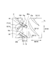
以下、説明の便宜上、第2実施形態に係るセグメント化されたプラズマアクチュエータをプラズマアクチュエータ80で表すものとする。図6は、本実施形態に係るプラズマアクチュエータの設置の一例を示す平面展開図である。第1実施形態と同じく、第2実施形態に係るプラズマアクチュエータ80も、図3(a)及び図3(b)に示すプラズマ42を発生し、プラズマ42はケーシング7の周方向に分布する。ただし、プラズマアクチュエータ80は、各可変静翼12に対して個別に設けられている。
Hereinafter, for convenience of explanation, the segmented plasma actuator according to the second embodiment is represented by a
プラズマアクチュエータ80は、プラズマアクチュエータ40A(図3(a)参照)或いはプラズマアクチュエータ40B(図3(b)参照)と同様の構成を備える。即ち、プラズマアクチュエータ80は、少なくとも、絶縁基板を挟んだ2つの電極を備えている。
The
図6に示すように、プラズマアクチュエータ80は、対応する可変静翼12(翼体16)のコード方向16gに対して交差する方向Dに延伸している。例えば、方向Dは、全閉状態にあるときの可変静翼12のコード方向16gに直交している。プラズマアクチュエータ80の各電極も方向Dに延伸する。従って、プラズマ42によって誘起されるジェット41は、ケーシング7の内周面7aに沿って、概ね方向Dと直交する方向に流れる。なお、方向Dに直交するプラズマアクチュエータ80の幅80wは、方向Dに沿って一定でもよく、徐々に変化してもよい。
As shown in FIG. 6, the
プラズマアクチュエータ80が、可変静翼12が全閉状態にあるときのクリアランス32と、可変静翼12が全開状態にあるときのクリアランス32を交差するように設けられている。また、プラズマアクチュエータ80によるプラズマ42の発生タイミング及び持続期間は、第1実施形態のものと同様である。従って、可変静翼12が何れの状態に置かれても、プラズマ42をクリアランス32と交差するように発生させることができ、漏れ流れ60(図5参照)を下流側の動翼13に向けて偏向させることができる。また、第2実施形態でもジェット41による漏れ流れ60の偏向によって、第1実施形態と同様の効果が得られる。
A
なお、プラズマアクチュエータ80は、可変静翼12が半開状態にある時にプラズマ42を発生してもよい。換言すれば、プラズマ42の発生は、可変静翼12が半開状態にある時のみに限られてもよい。ここで言う「半開」とは、可変静翼12が、全閉状態の角度と全開状態の角度の間の角度に置かれた状態を指す。圧縮機3において可変静翼12が設置されている段は、可変静翼12が半開状態にあるときにストールが誘起されやすい。このような状態のときに限り、プラズマ42を発生させることで、プラズマアクチュエータ80の消費電力を削減できる。ストールの発生を阻止する観点からは、第1実施形態と同様に圧力センサ51などを用いて、動翼13によるストールの予兆が検知されたときにプラズマ42を発生してもよい。
The
以上、添付図面を参照しながら本開示の一実施形態について説明したが、本開示はかかる実施形態に限定されないことは言うまでもない。当業者であれば、特許請求の範囲に記載された範疇において、各種の変更例または修正例に想到し得ることは明らかであり、それらについても当然に本開示の技術的範囲に属するものと了解される。
Although the embodiment of the present disclosure has been described above with reference to the accompanying drawings, it goes without saying that the present disclosure is not limited to such an embodiment. It is apparent that those skilled in the art can conceive of various modifications and alterations within the scope of the claims, and it is understood that they are naturally within the technical scope of the present disclosure. Be done.
Claims (9)
揺動中心としての翼軸を有し、静翼或いは入口案内翼として前記ケーシング内に設けられ、前記ケーシングの周方向に配列する可変静翼と、
前記ケーシング内において前記可変静翼の後縁側に設けられ、前記ケーシングの周方向に配列する動翼と、
前記可変静翼と前記ケーシングの前記内周面との間のクリアランスと交差し、且つ、前記ケーシングの周方向に向けて環状に分布するプラズマを生成し、前記ケーシングの内周面に取り付けられるプラズマアクチュエータと、
を備える
軸流圧縮機。 With a cylindrical casing,
A variable stator blade having a blade axis as a swing center, provided as a stator blade or an inlet guide blade in the casing and arranged in the circumferential direction of the casing;
A moving blade provided on a trailing edge side of the variable stationary blade in the casing and arranged in the circumferential direction of the casing;
A plasma is generated that intersects the clearance between the variable stator vanes and the inner circumferential surface of the casing, and is annularly distributed in the circumferential direction of the casing, and is attached to the inner circumferential surface of the casing An actuator,
Axial flow compressor comprising:
請求項1に記載の軸流圧縮機。 The plasma actuator is divided into a plurality of segments according to the corresponding variable vanes,
The axial flow compressor according to claim 1.
請求項1又は2に記載の軸流圧縮機。 The plasma actuator is mounted between the row of blade axes of the variable stator blades and the row of moving blades on the inner circumferential surface of the casing.
The axial flow compressor according to claim 1.
請求項1から3のうちの何れか一項に記載の軸流圧縮機。 The plasma actuator is located in a first region between the blade shaft and a trailing edge of the fully-variable vane in the axial direction of the casing.
The axial flow compressor according to any one of claims 1 to 3.
請求項4に記載の軸流圧縮機。 The plasma actuator is further located in a second region between the trailing edge of the variable vane in the fully closed state and the trailing edge of the variable vane in the fully open state in the axial direction of the casing.
The axial flow compressor according to claim 4.
請求項5に記載の軸流圧縮機。 The generation of plasma in the second region by the plasma actuator is controlled according to the opening degree of the variable stator blade.
The axial flow compressor according to claim 5.
請求項1又は2に記載の軸流圧縮機。 Each segment of the plasma actuator extends in a direction intersecting the code direction of the corresponding variable stator blade
The axial flow compressor according to claim 1.
請求項7に記載の軸流圧縮機。 The plasma actuator generates plasma when the variable stator vane is in a half open state.
The axial flow compressor according to claim 7.
請求項1から8のうちの何れか一項に記載の軸流圧縮機。
The plasma actuator generates a plasma when a sign of a stall due to the moving blade is detected.
The axial flow compressor according to any one of claims 1 to 8.
Priority Applications (3)
| Application Number | Priority Date | Filing Date | Title |
|---|---|---|---|
| EP18892377.5A EP3730800B1 (en) | 2017-12-21 | 2018-10-10 | Axial compressor |
| JP2019560821A JP6881608B2 (en) | 2017-12-21 | 2018-10-10 | Axial flow compressor |
| US16/903,651 US11236630B2 (en) | 2017-12-21 | 2020-06-17 | Axial compressor |
Applications Claiming Priority (2)
| Application Number | Priority Date | Filing Date | Title |
|---|---|---|---|
| JP2017245080 | 2017-12-21 | ||
| JP2017-245080 | 2017-12-21 |
Related Child Applications (1)
| Application Number | Title | Priority Date | Filing Date |
|---|---|---|---|
| US16/903,651 Continuation US11236630B2 (en) | 2017-12-21 | 2020-06-17 | Axial compressor |
Publications (1)
| Publication Number | Publication Date |
|---|---|
| WO2019123787A1 true WO2019123787A1 (en) | 2019-06-27 |
Family
ID=66993330
Family Applications (1)
| Application Number | Title | Priority Date | Filing Date |
|---|---|---|---|
| PCT/JP2018/037724 Ceased WO2019123787A1 (en) | 2017-12-21 | 2018-10-10 | Axial flow compressor |
Country Status (4)
| Country | Link |
|---|---|
| US (1) | US11236630B2 (en) |
| EP (1) | EP3730800B1 (en) |
| JP (1) | JP6881608B2 (en) |
| WO (1) | WO2019123787A1 (en) |
Cited By (1)
| Publication number | Priority date | Publication date | Assignee | Title |
|---|---|---|---|---|
| CN112129213A (en) * | 2020-10-26 | 2020-12-25 | 南京航空航天大学 | Tip Clearance Measurement System and Measurement Method Based on Pulse Dielectric Barrier Discharge |
Families Citing this family (7)
| Publication number | Priority date | Publication date | Assignee | Title |
|---|---|---|---|---|
| FR3094746B1 (en) * | 2019-04-03 | 2021-03-05 | Safran Aircraft Engines | VARIABLE TIMING STATOR VANE FOR AN AIRCRAFT TURBOMACHINE |
| FR3101914B1 (en) * | 2019-10-10 | 2021-11-12 | Safran Aircraft Engines | Variable-pitch stator vane with aerodynamic fins |
| FR3109959B1 (en) * | 2020-05-06 | 2022-04-22 | Safran Helicopter Engines | Turbomachine compressor comprising a fixed wall provided with a shaped treatment |
| US11814969B2 (en) * | 2021-07-21 | 2023-11-14 | Pratt & Whitney Canada Corp. | Gas turbine engine with low-pressure compressor bypass |
| CN114321019A (en) * | 2021-12-27 | 2022-04-12 | 中国航发沈阳发动机研究所 | A compressor adjustable stator structure |
| US12378919B2 (en) * | 2023-09-22 | 2025-08-05 | Rtx Corporation | Direct horsepower and torque measurement system for gas turbine engine |
| CN119982680B (en) * | 2025-04-17 | 2025-07-11 | 西北工业大学太仓长三角研究院 | Gas power device and method for controlling flow field in blade tip area of gas power device |
Citations (9)
| Publication number | Priority date | Publication date | Assignee | Title |
|---|---|---|---|---|
| JP2000345997A (en) * | 1999-06-04 | 2000-12-12 | Ishikawajima Harima Heavy Ind Co Ltd | Variable vane mechanism of axial compressor |
| JP2010001821A (en) | 2008-06-20 | 2010-01-07 | Mitsubishi Heavy Ind Ltd | Variable stationary blade drive method and device for axial flow compressor |
| US7819626B2 (en) | 2006-10-13 | 2010-10-26 | General Electric Company | Plasma blade tip clearance control |
| JP2011508157A (en) | 2007-12-28 | 2011-03-10 | ゼネラル・エレクトリック・カンパニイ | Plasma compression system |
| US8096756B2 (en) | 2008-03-07 | 2012-01-17 | Pratt & Whitney Canada Corp. | Apparatus and method for controlling a compressor |
| JP2012159076A (en) * | 2011-01-28 | 2012-08-23 | General Electric Co <Ge> | Plasma actuation system to produce swirling flow |
| US8317457B2 (en) | 2007-12-28 | 2012-11-27 | General Electric Company | Method of operating a compressor |
| JP2014103094A (en) * | 2012-08-08 | 2014-06-05 | National Institute Of Advanced Industrial & Technology | Surface plasma actuator |
| JP2017053261A (en) | 2015-09-08 | 2017-03-16 | 国立研究開発法人産業技術総合研究所 | Pressure loss reduction device for fluid machinery |
Family Cites Families (5)
| Publication number | Priority date | Publication date | Assignee | Title |
|---|---|---|---|---|
| US20100047060A1 (en) * | 2007-12-28 | 2010-02-25 | Aspi Rustom Wadia | Plasma Enhanced Compressor |
| US8348592B2 (en) | 2007-12-28 | 2013-01-08 | General Electric Company | Instability mitigation system using rotor plasma actuators |
| US20100047055A1 (en) | 2007-12-28 | 2010-02-25 | Aspi Rustom Wadia | Plasma Enhanced Rotor |
| US8585356B2 (en) * | 2010-03-23 | 2013-11-19 | Siemens Energy, Inc. | Control of blade tip-to-shroud leakage in a turbine engine by directed plasma flow |
| FR3010464B1 (en) * | 2013-09-11 | 2017-12-22 | Snecma | VARIABLE SETTING RECTIFIER STAGE FOR TURBOMACHINE COMPRESSOR COMPRISING A BRUSHED GASKET |
-
2018
- 2018-10-10 JP JP2019560821A patent/JP6881608B2/en active Active
- 2018-10-10 EP EP18892377.5A patent/EP3730800B1/en active Active
- 2018-10-10 WO PCT/JP2018/037724 patent/WO2019123787A1/en not_active Ceased
-
2020
- 2020-06-17 US US16/903,651 patent/US11236630B2/en active Active
Patent Citations (9)
| Publication number | Priority date | Publication date | Assignee | Title |
|---|---|---|---|---|
| JP2000345997A (en) * | 1999-06-04 | 2000-12-12 | Ishikawajima Harima Heavy Ind Co Ltd | Variable vane mechanism of axial compressor |
| US7819626B2 (en) | 2006-10-13 | 2010-10-26 | General Electric Company | Plasma blade tip clearance control |
| JP2011508157A (en) | 2007-12-28 | 2011-03-10 | ゼネラル・エレクトリック・カンパニイ | Plasma compression system |
| US8317457B2 (en) | 2007-12-28 | 2012-11-27 | General Electric Company | Method of operating a compressor |
| US8096756B2 (en) | 2008-03-07 | 2012-01-17 | Pratt & Whitney Canada Corp. | Apparatus and method for controlling a compressor |
| JP2010001821A (en) | 2008-06-20 | 2010-01-07 | Mitsubishi Heavy Ind Ltd | Variable stationary blade drive method and device for axial flow compressor |
| JP2012159076A (en) * | 2011-01-28 | 2012-08-23 | General Electric Co <Ge> | Plasma actuation system to produce swirling flow |
| JP2014103094A (en) * | 2012-08-08 | 2014-06-05 | National Institute Of Advanced Industrial & Technology | Surface plasma actuator |
| JP2017053261A (en) | 2015-09-08 | 2017-03-16 | 国立研究開発法人産業技術総合研究所 | Pressure loss reduction device for fluid machinery |
Non-Patent Citations (1)
| Title |
|---|
| See also references of EP3730800A4 |
Cited By (2)
| Publication number | Priority date | Publication date | Assignee | Title |
|---|---|---|---|---|
| CN112129213A (en) * | 2020-10-26 | 2020-12-25 | 南京航空航天大学 | Tip Clearance Measurement System and Measurement Method Based on Pulse Dielectric Barrier Discharge |
| CN112129213B (en) * | 2020-10-26 | 2021-07-27 | 南京航空航天大学 | Tip Clearance Measurement System and Measurement Method Based on Pulse Dielectric Barrier Discharge |
Also Published As
| Publication number | Publication date |
|---|---|
| US20200308974A1 (en) | 2020-10-01 |
| US11236630B2 (en) | 2022-02-01 |
| EP3730800A1 (en) | 2020-10-28 |
| JPWO2019123787A1 (en) | 2020-12-17 |
| JP6881608B2 (en) | 2021-06-02 |
| EP3730800B1 (en) | 2023-12-06 |
| EP3730800A4 (en) | 2021-09-01 |
Similar Documents
| Publication | Publication Date | Title |
|---|---|---|
| JP6881608B2 (en) | Axial flow compressor | |
| JP5410447B2 (en) | Instability mitigation system for rotors | |
| JP5518738B2 (en) | Instability mitigation system using rotor plasma actuator | |
| JP5550563B2 (en) | How to operate a compressor | |
| US20090065064A1 (en) | Compressor tip gap flow control using plasma actuators | |
| RU2458227C2 (en) | Boundary layer shielding system using upstream plasma (versions), and operating method of system | |
| JP2011508157A (en) | Plasma compression system | |
| JP2011508148A (en) | Compressor tip clearance control system including plasma actuator, compressor, and gas turbine engine including the control system | |
| US9963981B2 (en) | Pitch change mechanism for shrouded fan with low fan pressure ratio | |
| JP2011508154A (en) | Compressor and gas turbine engine with plasma actuator | |
| JP2011508149A (en) | Plasma compressor | |
| US8585356B2 (en) | Control of blade tip-to-shroud leakage in a turbine engine by directed plasma flow | |
| CN101988392A (en) | Rotor blades for turbine engines | |
| JP2015140807A (en) | High chord blade with two partial span shrouds and curved dovetail | |
| US20160061054A1 (en) | Structural frame integrated with variable-vectoring flow control for use in turbine systems | |
| US20170058782A1 (en) | Plasma actuated cascade flow vectoring | |
| CN106050335A (en) | Gas turbine diffuser and methods of assembling same | |
| JP2009197650A (en) | Gas turbine | |
| JP2006250147A (en) | Compressor | |
| JP2012159076A (en) | Plasma actuation system to produce swirling flow | |
| CN103032105A (en) | Noise reduction in a turbomachine, and a related method thereof | |
| US11181001B2 (en) | Stator vane and rotary machine | |
| JP7400314B2 (en) | Fan or compressor airflow control device | |
| CN119435150A (en) | An open rotor engine | |
| CN118922617A (en) | Integration of an electric generator in the airflow of an aircraft engine |
Legal Events
| Date | Code | Title | Description |
|---|---|---|---|
| 121 | Ep: the epo has been informed by wipo that ep was designated in this application |
Ref document number: 18892377 Country of ref document: EP Kind code of ref document: A1 |
|
| ENP | Entry into the national phase |
Ref document number: 2019560821 Country of ref document: JP Kind code of ref document: A |
|
| NENP | Non-entry into the national phase |
Ref country code: DE |
|
| ENP | Entry into the national phase |
Ref document number: 2018892377 Country of ref document: EP Effective date: 20200721 |