WO2019123952A1 - Rotor et moteur - Google Patents
Rotor et moteur Download PDFInfo
- Publication number
- WO2019123952A1 WO2019123952A1 PCT/JP2018/042841 JP2018042841W WO2019123952A1 WO 2019123952 A1 WO2019123952 A1 WO 2019123952A1 JP 2018042841 W JP2018042841 W JP 2018042841W WO 2019123952 A1 WO2019123952 A1 WO 2019123952A1
- Authority
- WO
- WIPO (PCT)
- Prior art keywords
- rotor
- shaft
- rotor core
- fitting
- convex portion
- Prior art date
- Legal status (The legal status is an assumption and is not a legal conclusion. Google has not performed a legal analysis and makes no representation as to the accuracy of the status listed.)
- Ceased
Links
Images



Classifications
-
- H—ELECTRICITY
- H02—GENERATION; CONVERSION OR DISTRIBUTION OF ELECTRIC POWER
- H02K—DYNAMO-ELECTRIC MACHINES
- H02K1/00—Details of the magnetic circuit
- H02K1/06—Details of the magnetic circuit characterised by the shape, form or construction
- H02K1/22—Rotating parts of the magnetic circuit
-
- H—ELECTRICITY
- H02—GENERATION; CONVERSION OR DISTRIBUTION OF ELECTRIC POWER
- H02K—DYNAMO-ELECTRIC MACHINES
- H02K1/00—Details of the magnetic circuit
- H02K1/06—Details of the magnetic circuit characterised by the shape, form or construction
- H02K1/22—Rotating parts of the magnetic circuit
- H02K1/28—Means for mounting or fastening rotating magnetic parts on to, or to, the rotor structures
Definitions
- the present invention relates to a rotor and a motor.
- Patent Document 1 discloses a structure in which a shaft and a rotor core are key-fitted.
- An object of one aspect of the present invention is to provide a rotor that can suppress slippage between a rotor core and a shaft.
- a rotor according to one aspect of the present invention is a rotor used for an inner rotor type motor, and is supported by a shaft centered on a vertically extending central axis, a rotor core fixed to the shaft, and the rotor core And a rotor magnet.
- the rotor core is provided with a central hole into which the shaft is press-fitted.
- the inner circumferential surface of the central hole is provided with a plurality of fitting convex portions that protrude inward in the radial direction along the circumferential direction and contact the shaft at a tip end surface.
- the outer circumferential surface of the shaft is provided with a groove extending along the axial direction and facing the tip surface in the radial direction.
- a rotor capable of suppressing idling of the rotor core and the shaft.
- FIG. 1 is a schematic cross-sectional view along the central axis of the motor of one embodiment.
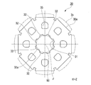
- FIG. 2 is a plan view of a rotor core of an embodiment.
- FIG. 3 is a partial cross-sectional view of a rotor of one embodiment.
- FIG. 4 is an enlarged view of a region IV of FIG.
- FIG. 5 is a plan view of a rotor core of a modification.
- the Z axis is shown as appropriate.
- the Z-axis direction of each drawing is a direction parallel to the axial direction of the central axis J shown in FIG. Further, in the following description, the positive side (+ Z side) in the Z-axis direction is referred to as "upper side”, and the negative side (-Z side) in the Z-axis direction is referred to as "lower side”. Note that the upper and lower sides are directions used merely for the purpose of explanation, and do not limit the actual positional relationship or direction.
- a direction (Z-axis direction) parallel to the central axis J is simply referred to as “axial direction” or “vertical direction”, and a radial direction centered on the central axis J is simply referred to as “radial direction”.
- the circumferential direction around the central axis J that is, around the axis of the central axis J, is simply referred to as “circumferential direction”.
- plane view means a state viewed from the axial direction.
- FIG. 1 is a schematic cross-sectional view along the central axis J of the motor 1 according to one embodiment.
- the motor 1 includes a rotor 3, a stator 10, a housing 2, a bearing holder 5, an upper bearing 6A, and a lower bearing 6B.
- the motor 1 of the present embodiment is an inner rotor type motor in which the rotor 3 is disposed radially inside the stator 10.
- the housing 2 is in the form of a cylinder that opens upward.
- the housing 2 accommodates the rotor 3, the stator 10 and the bearing holder 5.
- the housing 2 has a cylindrical portion 2a and a bottom 2b.
- the cylindrical portion 2 a surrounds the stator 10 from the outer side in the radial direction.
- the bottom 2b is located at the lower end of the cylindrical portion 2a.
- a lower bearing holding portion 2c for holding the lower bearing 6B is provided at the center of the bottom portion 2b in plan view.
- the bearing holder 5 is located above the stator 10.
- the bearing holder 5 is held on the inner peripheral surface of the housing 2.
- the bearing holder 5 holds the upper bearing 6A in the upper bearing holding portion 5a.
- the stator 10 is annularly disposed around the central axis J.
- the stator 10 is located radially outward of the rotor 3.
- the stator 10 is radially opposed to the rotor 3 via a gap.
- the stator 10 is fixed to the inner circumferential surface of the housing 2.
- the stator 10 has an annular stator core 11, a pair of insulators 14 mounted on the stator core 11 in the vertical direction, and a coil 13 mounted on the stator core 11 via the insulators 14.
- the rotor 3 is used for an inner rotor type motor 1.
- the rotor 3 rotates around a central axis J extending in the vertical direction.
- the rotor 3 has a shaft 90, a plurality of rotor cores 30, and a plurality of rotor magnets 3b.
- the shaft 90 extends in the vertical direction around a central axis J extending in the vertical direction (axial direction).
- the shaft 90 has a circular cross-sectional shape orthogonal to the central axis J.
- the shaft 90 is rotatably supported around the central axis J by the upper bearing 6A and the lower bearing 6B.
- Rotor core 30 is fixed to outer circumferential surface 90 a of shaft 90.
- the rotor 3 of the present embodiment is provided with two rotor cores (first rotor core 30A and second rotor core 30B) aligned in the axial direction.
- the first rotor core 30A and the second rotor core 30B have the same shape. In the present specification, when the first rotor core 30A and the second rotor core 30B are not distinguished from one another, these are simply referred to as the rotor core 30.
- the rotor magnets 3b are fixed to the outer peripheral surfaces of the first rotor core 30A and the second rotor core 30B, respectively. That is, the rotor magnet 3 b is supported by the rotor core 30.
- the first rotor core 30A and the second rotor core 30B are fixed to the shaft 90 in a state where the magnetic poles of the rotor magnet 3b are shifted in the circumferential direction. That is, the first rotor core 30A and the second rotor core 30B are arranged to be mutually offset in the rotational direction at a predetermined skew angle. Thereby, the cogging torque of the motor 1 can be reduced.
- the rotor 3 exemplifies the case of having two rotor cores 30.
- the rotor 3 may have three or more rotor cores disposed with a skew angle.
- the rotor core 30 is configured by laminating a plurality of electromagnetic steel plates 39 along the axial direction.
- the plurality of electromagnetic steel plates 39 have the same shape. Therefore, the shape of the rotor core 30 viewed from the axial direction matches the shape viewed from the axial direction of each of the electromagnetic steel plates 39.
- FIG. 2 is a plan view of the rotor core 30 according to one embodiment.
- the rotor core 30 extends in a uniform cross section along the axial direction.
- the rotor core 30 has a substantially polygonal outer shape when viewed in the axial direction.
- the rotor core 30 is octagonal when viewed in the axial direction. That is, the rotor core 30 of the present embodiment is an octagonal prism.
- the rotor core 30 has eight holding surfaces 30 a facing radially outward.
- the eight holding surfaces 30 a constitute the outer peripheral surface of the rotor core 30.
- the holding surfaces 30a are arranged along the circumferential direction.
- the holding surface 30a is a surface orthogonal to the radial direction.
- the rotor magnet 3b is fixed to the holding surface 30a via an adhesive or the like.
- the rotor magnet 3b may be fixed by a cylindrical rotor cover. Therefore, eight rotor magnets 3b are provided in the rotor 3 of the present embodiment.
- the eight rotor magnets 3b are arranged alternately in the magnetic pole direction along the circumferential direction.
- the number of holding surfaces 30a of the rotor core 30 and the number of rotor magnets 3b provided on the rotor 3 are an example, and the present invention is not limited to this embodiment.
- the rotor core 30 is provided with a plurality of through holes 35.
- the rotor core 30 is provided with eight through holes 35.
- the through hole 35 penetrates in the axial direction.
- the plurality of through holes 35 are arranged at equal intervals along the circumferential direction.
- the inside of the through hole 35 is a cavity.
- the rotor core 30 is provided with a central hole 31 located at the center in plan view.
- the central hole 31 penetrates in the axial direction.
- the central hole 31 is substantially circular around the central axis J.
- the shaft 90 is press-fitted into the central hole 31.
- a plurality of fitting projections 32 are provided on the inner peripheral surface of the central hole 31.
- eight fitting convex portions 32 are provided on the inner peripheral surface of the central hole 31.
- the number of fitting projections 32 matches the number of rotor magnets 3 b and the number of through holes 35. Further, one rotor magnet 3 b is provided on the radial outside of one fitting protrusion 32.
- the inner circumferential surface of the central hole means a surface which constitutes the central hole in the rotor core.
- the plurality of fitting projections 32 are arranged at equal intervals along the circumferential direction.
- the fitting convex portion 32 protrudes radially inward.
- the fitting convex portion 32 has a tip surface 32 a facing inward in the radial direction.
- the tip end surface 32a has an arc shape centering on the central axis J, and extends uniformly along the axial direction.
- the fitting convex portion 32 contacts the shaft 90 at the tip end surface 32 a.
- one through hole 35 is provided on the radial outside of one fitting protrusion 32.
- the inside of the through hole 35 is a cavity. Therefore, as compared with the case where a resin material or the like is filled in the through hole 35, the fitting convex portion 32 located inward of the through hole 35 in the radial direction can be easily deformed.
- the inside of the through hole 35 may be filled with a resin material or the like which is more easily elastically deformed than the material forming the rotor core 30. In such a case, due to the difference in elastic modulus between the material of the rotor core 30 and the material filled in the through hole 35, the fitting convex portion 32 is easily deformed radially outward.
- FIG. 3 is a partial cross-sectional view of the rotor 3.
- FIG. 4 is an enlarged view of a region IV of FIG.
- a plurality of (four in the present embodiment) groove portions 91 are provided on the outer peripheral surface 90 a of the shaft 90.
- the plurality of groove portions 91 are arranged at equal intervals along the circumferential direction.
- the grooves 91 extend linearly along the axial direction.
- the groove portion 91 faces the tip end surface 32 a of the fitting convex portion 32 in the radial direction.
- the eight fitting projections 32 include four first fitting projections 32A and four second fitting projections 32B.
- the first fitting projection 32A faces the groove 91 at the tip end face 32a.
- the second fitting convex portion 32B does not face the groove portion 91 at the tip end surface 32a. That is, the second fitting convex portion 32B contacts the outer peripheral surface 90a of the shaft 90 in the entire area of the tip end surface 32a.
- the first fitting convex portion 32A and the second fitting convex portion 32B have the same shape. That is, in the state before press-fitting of the shaft 90, the first fitting convex portion 32A and the second fitting convex portion 32B have the same projecting height and the same width dimension in the circumferential direction.
- the groove portion 91 has a V-like shape in which the width in the circumferential direction becomes narrower toward the inside in the radial direction.
- the groove portion 91 has a pair of side surfaces 91 b and a bottom surface 91 a.
- the pair of side surfaces 91 b extend radially outward from the bottom surface 91 a.
- the pair of side surfaces 91 b extends in the direction away from each other as it goes radially outward.
- the bottom surface 91 a faces radially outward.
- the bottom surface 91a smoothly connects the lower ends of the pair of side surfaces 91b.
- the cross-sectional shape of the groove part 91 is not limited to this embodiment.
- the cross-sectional shape of the groove portion 91 may be a rectangular shape or an arc shape.
- the groove portion 91 can be formed, for example, by pressing a tool having a V-shaped tip portion against the outer peripheral surface 90 a of the shaft 90 and moving it in the axial direction. Thereby, the outer peripheral surface 90a of the shaft 90 pressed against the tool is plastically deformed, and the V-shaped groove portion 91 is formed. Moreover, when forming the groove part 91 through such a process, the convex part by plastic deformation is shape
- the distal end surface 32a of the first fitting convex portion 32A facing the groove portion 91 is deformed convex portion 32b which is deformed by contact with the shaft 90 and enters the groove portion 91, and positions on both sides in the circumferential direction of the deformed convex portion 32b And a pair of contact portions 32c.
- the tip end surface 32a of the first fitting projection 32A contacts the outer peripheral surface 90a of the shaft 90 at the contact portion 32c.
- the fitting convex portion 32 elastically deforms outward in the radial direction.
- the distal end surface 32 a of the first fitting convex portion 32 ⁇ / b> A receives no stress from the outer peripheral surface 90 a of the shaft 90 in a region facing the groove portion 91.
- the rate of elastic deformation becomes smaller compared to the other regions.
- the deformation convex part 32b is provided in the front end surface 32a of the 1st fitting convex part 32A.
- FIG. 4 illustrates the ratio of the dimension (height dimension) in the radial direction of the deformation convex portion 32b to the depth dimension of the groove portion 91 for the purpose of emphasizing the deformation convex portion 32b. is there.
- the depth dimension of the groove 91 is, for example, 10% or less of the diameter of the shaft 90.
- the height dimension of the deformation convex portion is, for example, 1 ⁇ m or more and 30 ⁇ m or less.
- a surface pressure is generated in a region (contact portion 32c) which is the tip end surface 32a of the first fitting projection 32A and in contact with the outer peripheral surface 90a of the shaft 90.
- no surface pressure is generated in the region (deformed convex portion 32 b) which is the tip surface 32 a of the first fitting convex portion 32 ⁇ / b> A and faces the groove portion 91.
- the groove 91 extends in the axial direction. According to the present embodiment, at the tip end surface 32a, the boundary where the surface pressure changes extremely is provided linearly along the axial direction.
- the shaft 90 is deformed at the boundary portion by providing the boundary portion where the surface pressure changes extremely on the front end surface 32a, and the front end surface 32a of the first fitting convex portion 32A against the outer peripheral surface 90a of the shaft 90 Sliding can be suppressed, and slippage between the rotor core 30 and the shaft 90 can be suppressed.
- the distal end surface 32 a of the first fitting convex portion 32 ⁇ / b> A includes the deformation convex portion 32 b which intrudes into the groove portion 91.
- the deformation convex portion 32 b contacts the side surface 91 b of the groove portion 91 at the root portion.
- the deformation convex portion 32 b functions as an anchor when the first fitting convex portion 32 A tries to move in the circumferential direction relatively to the outer circumferential surface 90 a of the shaft 90. For this reason, it is possible to suppress that the tip end surface 32a of the first fitting convex portion 32A slips on the outer peripheral surface 90a of the shaft 90, and idle rotation of the rotor core 30 and the shaft 90 is suppressed.
- a gap is provided between the tip of the deformation convex portion 32 b and the bottom surface 91 a of the groove portion 91. For this reason, the tip end surface 32a of the first fitting convex portion 32A can be sufficiently deformed radially inward to provide the deformed convex portion 32b.
- the rotor core 30 contacts the outer peripheral surface 90 a of the shaft 90 at the tip end surface 32 a of the fitting convex portion 32 provided on the inner peripheral surface of the central hole 31. For this reason, as compared with the case where the entire inner peripheral surface of the central hole 31 contacts the outer peripheral surface 90 a of the shaft 90, the contact pressure of the contact surface becomes higher. As a result, a part of the front end surface 32a of the first fitting convex portion 32A facing the groove portion 91 easily intrudes into the groove portion 91 as the deformation convex portion 32b, and idle rotation of the rotor core 30 and the shaft 90 is caused. It can be effectively suppressed.
- the circumferential lengths d2 and d2 of the pair of contact portions 32c positioned on both sides in the circumferential direction of the deformation convex portion 32b be equal to each other.
- the circumferential length d1 of the deformation convex portion 32b is preferably shorter than the sum of the circumferential lengths d2 and d2 of the pair of contact portions 32c.
- the positioning accuracy of the rotor core 30 can be enhanced while suppressing the idle rotation of the rotor core 30 with respect to the shaft 90.
- the circumferential length d1 of the deformation convex portion 32b may be longer than the sum of the circumferential lengths d2 and d2 of the pair of contact portions 32c. In this case, the slippage suppressing effect of the deformation convex portion 32b can be enhanced.
- the first fitting convex portions 32A and the second fitting convex portions 32B are alternately arranged along the circumferential direction.
- the tip end surface 32a of the first fitting convex portion 32A deforms inward in the radial direction in a region facing the groove portion 91 to form a deformed convex portion 32b.
- the tip end surface 32a of the first fitting convex portion 32A is distorted in an arc shape in contact with the outer peripheral surface 90a of the shaft 90. For this reason, when the tip end surfaces 32 a of all the fitting convex portions 32 face the groove portions 91, the coaxiality of the shaft 90 and the rotor core 30 may be reduced.
- the fitting projection 32 includes the first fitting projection 32A facing the groove 91 and the second fitting projection 32B not facing the groove 91 in the front end face 32a. . Therefore, in the first fitting convex portion 32A, it is possible to suppress the idle rotation between the rotor core 30 and the shaft 90, and secure the coaxiality between the rotor core 30 and the shaft 90 in the second fitting convex portion 32B. it can.
- the plurality of first fitting convex portions 32A are arranged at equal intervals in the circumferential direction. For this reason, the symmetry of the rotor core 30 can be maintained, and the variation in coaxiality between the rotor core 30 and the shaft 90 can be effectively suppressed. Furthermore, according to the present embodiment, the first fitting convex portions 32A and the second fitting convex portions 32B are alternately arranged in the circumferential direction. Therefore, the effect of suppressing the variation in the degree of coaxiality between the rotor core 30 and the shaft 90 can be enhanced.
- the plurality of groove portions 91 may be diametrically opposed to one fitting protrusion 32.
- at least one groove portion 91 may be provided on the outer peripheral surface 90 a of the shaft 90. That is, the plurality of fitting protrusions 32 may include at least one first fitting protrusion 32A facing the groove 91.
- FIG. 5 is a plan view of a rotor core 130 of a modified example that can be adopted for the motor 1 of the above-described embodiment.
- a rotor magnet 103b fixed to the outer peripheral surface 130a of the rotor core 130 is illustrated by a two-dot chain line.
- symbol is attached
- the modified rotor core 130 extends in the axial direction with a uniform cross section.
- the rotor core 130 is circular around the central axis J when viewed in the axial direction. That is, in the present embodiment, the rotor core 130 is cylindrical.
- the rotor core 130 has an outer circumferential surface 130 a facing radially outward.
- the rotor magnet 103 b is fixed to the outer peripheral surface 130 a via an adhesive or the like.
- the rotor magnet 103b may be fixed by a cylindrical rotor cover.
- the rotor magnet 103b of this modification is annular.
- a plurality of N poles and S poles are alternately arranged and magnetized along the circumferential direction. That is, the rotor magnet 103b has an annular shape in which the magnetic poles are arranged along the circumferential direction.
- the magnetic poles of the N pole and the S pole of the rotor magnet 103b may be spirally magnetized, respectively. By magnetizing in this manner, the cogging torque of the motor can be reduced.
- the rotors and the motors provided with the rotors of the various embodiments described above and variations thereof are mounted on an electric power steering apparatus. Moreover, these rotors and motors are not limited to the electric power steering device, and may be mounted on any device.
Landscapes
- Engineering & Computer Science (AREA)
- Power Engineering (AREA)
- Iron Core Of Rotating Electric Machines (AREA)
Abstract
L'invention concerne un rotor utilisé pour un moteur de type à rotor intérieur, le rotor incluant : un arbre centré sur un axe central s'étendant verticalement ; un noyau de rotor fixé à l'arbre ; et un aimant de rotor supporté par le noyau de rotor. Le noyau de rotor comporte un trou central, dans lequel l'arbre est formé par emboutissage. Une surface périphérique intérieure du trou central comporte une pluralité d'excroissances d'insertion qui sont agencées le long de la direction circonférentielle, dépassent radialement vers le côté intérieur, et entrent en contact avec l'arbre sur sa surface d'extrémité distale. Une surface périphérique extérieure de l'arbre comporte des rainures qui sont agencées le long de la direction axiale et qui font face à la surface d'extrémité distale dans la direction radiale.
Priority Applications (1)
| Application Number | Priority Date | Filing Date | Title |
|---|---|---|---|
| JP2019560895A JPWO2019123952A1 (ja) | 2017-12-18 | 2018-11-20 | ロータおよびモータ |
Applications Claiming Priority (2)
| Application Number | Priority Date | Filing Date | Title |
|---|---|---|---|
| JP2017-241994 | 2017-12-18 | ||
| JP2017241994 | 2017-12-18 |
Publications (1)
| Publication Number | Publication Date |
|---|---|
| WO2019123952A1 true WO2019123952A1 (fr) | 2019-06-27 |
Family
ID=66994675
Family Applications (1)
| Application Number | Title | Priority Date | Filing Date |
|---|---|---|---|
| PCT/JP2018/042841 Ceased WO2019123952A1 (fr) | 2017-12-18 | 2018-11-20 | Rotor et moteur |
Country Status (2)
| Country | Link |
|---|---|
| JP (1) | JPWO2019123952A1 (fr) |
| WO (1) | WO2019123952A1 (fr) |
Cited By (4)
| Publication number | Priority date | Publication date | Assignee | Title |
|---|---|---|---|---|
| CN111884370A (zh) * | 2020-06-16 | 2020-11-03 | 广东威灵电机制造有限公司 | 一种转子组件和电机 |
| WO2021144849A1 (fr) * | 2020-01-14 | 2021-07-22 | 三菱電機株式会社 | Machine électrique rotative |
| EP4178083A4 (fr) * | 2020-07-02 | 2023-12-27 | Toyota Jidosha Kabushiki Kaisha | Noyau de rotor |
| WO2024126269A1 (fr) * | 2022-12-14 | 2024-06-20 | Valeo Eautomotive Germany Gmbh | Noyau de rotor stratifié, machine électrique et véhicule |
Citations (6)
| Publication number | Priority date | Publication date | Assignee | Title |
|---|---|---|---|---|
| JPS55145847U (fr) * | 1979-04-09 | 1980-10-20 | ||
| JP2003111326A (ja) * | 2001-09-26 | 2003-04-11 | Asmo Co Ltd | 回転電機用電機子及び回転電機 |
| JP2009189105A (ja) * | 2008-02-04 | 2009-08-20 | Mitsuba Corp | 電動モータ |
| JP2015047051A (ja) * | 2013-08-29 | 2015-03-12 | 株式会社デンソー | 回転子、および、これを用いた回転電機 |
| JP2015073387A (ja) * | 2013-10-03 | 2015-04-16 | 日立オートモティブシステムズ株式会社 | 回転子鉄心、回転子、および、回転電機 |
| JP2015097436A (ja) * | 2013-11-15 | 2015-05-21 | 株式会社デンソー | 回転電機のロータ及びそのロータを備えた回転電機 |
-
2018
- 2018-11-20 JP JP2019560895A patent/JPWO2019123952A1/ja active Pending
- 2018-11-20 WO PCT/JP2018/042841 patent/WO2019123952A1/fr not_active Ceased
Patent Citations (6)
| Publication number | Priority date | Publication date | Assignee | Title |
|---|---|---|---|---|
| JPS55145847U (fr) * | 1979-04-09 | 1980-10-20 | ||
| JP2003111326A (ja) * | 2001-09-26 | 2003-04-11 | Asmo Co Ltd | 回転電機用電機子及び回転電機 |
| JP2009189105A (ja) * | 2008-02-04 | 2009-08-20 | Mitsuba Corp | 電動モータ |
| JP2015047051A (ja) * | 2013-08-29 | 2015-03-12 | 株式会社デンソー | 回転子、および、これを用いた回転電機 |
| JP2015073387A (ja) * | 2013-10-03 | 2015-04-16 | 日立オートモティブシステムズ株式会社 | 回転子鉄心、回転子、および、回転電機 |
| JP2015097436A (ja) * | 2013-11-15 | 2015-05-21 | 株式会社デンソー | 回転電機のロータ及びそのロータを備えた回転電機 |
Cited By (5)
| Publication number | Priority date | Publication date | Assignee | Title |
|---|---|---|---|---|
| WO2021144849A1 (fr) * | 2020-01-14 | 2021-07-22 | 三菱電機株式会社 | Machine électrique rotative |
| CN111884370A (zh) * | 2020-06-16 | 2020-11-03 | 广东威灵电机制造有限公司 | 一种转子组件和电机 |
| CN111884370B (zh) * | 2020-06-16 | 2021-08-31 | 广东威灵电机制造有限公司 | 一种转子组件和电机 |
| EP4178083A4 (fr) * | 2020-07-02 | 2023-12-27 | Toyota Jidosha Kabushiki Kaisha | Noyau de rotor |
| WO2024126269A1 (fr) * | 2022-12-14 | 2024-06-20 | Valeo Eautomotive Germany Gmbh | Noyau de rotor stratifié, machine électrique et véhicule |
Also Published As
| Publication number | Publication date |
|---|---|
| JPWO2019123952A1 (ja) | 2020-12-03 |
Similar Documents
| Publication | Publication Date | Title |
|---|---|---|
| CN107408852B (zh) | 转子、旋转电机以及转子的制造方法 | |
| US9893573B2 (en) | Rotor of motor and such motor | |
| US9472984B2 (en) | Rotor for rotating electric machine | |
| WO2019123952A1 (fr) | Rotor et moteur | |
| JP2014236592A (ja) | 回転電機用ロータおよびその製造方法 | |
| JP6189699B2 (ja) | 回転子鉄心、回転子、および、回転電機 | |
| JP2008312321A (ja) | 回転子および回転電機 | |
| JP2015154665A (ja) | ロータ及びロータの製造方法 | |
| WO2019123950A1 (fr) | Rotor et moteur | |
| CN108631467A (zh) | 永磁体电动机 | |
| JP2013219931A (ja) | ロータ、これを備えた回転電機及びロータの製造方法 | |
| JP2015220846A (ja) | 回転電機の回転子 | |
| JP2015104176A (ja) | 回転電機ロータ | |
| JP5495045B2 (ja) | 回転電機の回転子 | |
| US10541571B2 (en) | Motor | |
| JP2017158282A (ja) | 回転電機 | |
| CN116235393A (zh) | 转子磁轭以及旋转电机 | |
| JP2010206944A (ja) | 永久磁石電動機 | |
| JP5917193B2 (ja) | ロータ、モータ及びロータの製造方法 | |
| JP5879848B2 (ja) | 埋込磁石形回転電機のロータ | |
| JP2012044789A (ja) | 回転電機およびその製造方法 | |
| JP7148566B2 (ja) | モータの回転子及びその製造方法 | |
| CN111835111A (zh) | 转子及表面磁铁型旋转电机 | |
| WO2019123962A1 (fr) | Rotor et moteur | |
| JP2014096869A (ja) | 磁石埋込型モータの回転子 |
Legal Events
| Date | Code | Title | Description |
|---|---|---|---|
| 121 | Ep: the epo has been informed by wipo that ep was designated in this application |
Ref document number: 18892738 Country of ref document: EP Kind code of ref document: A1 |
|
| ENP | Entry into the national phase |
Ref document number: 2019560895 Country of ref document: JP Kind code of ref document: A |
|
| NENP | Non-entry into the national phase |
Ref country code: DE |
|
| 122 | Ep: pct application non-entry in european phase |
Ref document number: 18892738 Country of ref document: EP Kind code of ref document: A1 |