WO2019124520A1 - Engin de chantier - Google Patents
Engin de chantier Download PDFInfo
- Publication number
- WO2019124520A1 WO2019124520A1 PCT/JP2018/047091 JP2018047091W WO2019124520A1 WO 2019124520 A1 WO2019124520 A1 WO 2019124520A1 JP 2018047091 W JP2018047091 W JP 2018047091W WO 2019124520 A1 WO2019124520 A1 WO 2019124520A1
- Authority
- WO
- WIPO (PCT)
- Prior art keywords
- work machine
- target surface
- control
- control unit
- bucket
- Prior art date
- Legal status (The legal status is an assumption and is not a legal conclusion. Google has not performed a legal analysis and makes no representation as to the accuracy of the status listed.)
- Ceased
Links
Images












Classifications
-
- E—FIXED CONSTRUCTIONS
- E02—HYDRAULIC ENGINEERING; FOUNDATIONS; SOIL SHIFTING
- E02F—DREDGING; SOIL-SHIFTING
- E02F9/00—Component parts of dredgers or soil-shifting machines, not restricted to one of the kinds covered by groups E02F3/00 - E02F7/00
- E02F9/20—Drives; Control devices
- E02F9/22—Hydraulic or pneumatic drives
- E02F9/2278—Hydraulic circuits
- E02F9/2296—Systems with a variable displacement pump
-
- E—FIXED CONSTRUCTIONS
- E02—HYDRAULIC ENGINEERING; FOUNDATIONS; SOIL SHIFTING
- E02F—DREDGING; SOIL-SHIFTING
- E02F3/00—Dredgers; Soil-shifting machines
- E02F3/04—Dredgers; Soil-shifting machines mechanically-driven
- E02F3/28—Dredgers; Soil-shifting machines mechanically-driven with digging tools mounted on a dipper- or bucket-arm, i.e. there is either one arm or a pair of arms, e.g. dippers, buckets
- E02F3/36—Component parts
- E02F3/42—Drives for dippers, buckets, dipper-arms or bucket-arms
- E02F3/43—Control of dipper or bucket position; Control of sequence of drive operations
- E02F3/435—Control of dipper or bucket position; Control of sequence of drive operations for dipper-arms, backhoes or the like
-
- E—FIXED CONSTRUCTIONS
- E02—HYDRAULIC ENGINEERING; FOUNDATIONS; SOIL SHIFTING
- E02F—DREDGING; SOIL-SHIFTING
- E02F9/00—Component parts of dredgers or soil-shifting machines, not restricted to one of the kinds covered by groups E02F3/00 - E02F7/00
- E02F9/20—Drives; Control devices
- E02F9/2025—Particular purposes of control systems not otherwise provided for
-
- E—FIXED CONSTRUCTIONS
- E02—HYDRAULIC ENGINEERING; FOUNDATIONS; SOIL SHIFTING
- E02F—DREDGING; SOIL-SHIFTING
- E02F9/00—Component parts of dredgers or soil-shifting machines, not restricted to one of the kinds covered by groups E02F3/00 - E02F7/00
- E02F9/20—Drives; Control devices
- E02F9/2025—Particular purposes of control systems not otherwise provided for
- E02F9/2033—Limiting the movement of frames or implements, e.g. to avoid collision between implements and the cabin
-
- E—FIXED CONSTRUCTIONS
- E02—HYDRAULIC ENGINEERING; FOUNDATIONS; SOIL SHIFTING
- E02F—DREDGING; SOIL-SHIFTING
- E02F9/00—Component parts of dredgers or soil-shifting machines, not restricted to one of the kinds covered by groups E02F3/00 - E02F7/00
- E02F9/20—Drives; Control devices
- E02F9/22—Hydraulic or pneumatic drives
- E02F9/226—Safety arrangements, e.g. hydraulic driven fans, preventing cavitation, leakage, overheating
-
- E—FIXED CONSTRUCTIONS
- E02—HYDRAULIC ENGINEERING; FOUNDATIONS; SOIL SHIFTING
- E02F—DREDGING; SOIL-SHIFTING
- E02F9/00—Component parts of dredgers or soil-shifting machines, not restricted to one of the kinds covered by groups E02F3/00 - E02F7/00
- E02F9/20—Drives; Control devices
- E02F9/22—Hydraulic or pneumatic drives
- E02F9/2278—Hydraulic circuits
- E02F9/2285—Pilot-operated systems
-
- E—FIXED CONSTRUCTIONS
- E02—HYDRAULIC ENGINEERING; FOUNDATIONS; SOIL SHIFTING
- E02F—DREDGING; SOIL-SHIFTING
- E02F9/00—Component parts of dredgers or soil-shifting machines, not restricted to one of the kinds covered by groups E02F3/00 - E02F7/00
- E02F9/26—Indicating devices
-
- E—FIXED CONSTRUCTIONS
- E02—HYDRAULIC ENGINEERING; FOUNDATIONS; SOIL SHIFTING
- E02F—DREDGING; SOIL-SHIFTING
- E02F9/00—Component parts of dredgers or soil-shifting machines, not restricted to one of the kinds covered by groups E02F3/00 - E02F7/00
- E02F9/26—Indicating devices
- E02F9/261—Surveying the work-site to be treated
- E02F9/262—Surveying the work-site to be treated with follow-up actions to control the work tool, e.g. controller
Definitions
- the present invention relates to a work machine on which machine control can be performed.
- the hydraulic shovel may be provided with a control system that assists the operator in the digging operation.
- the digging operation for example, an instruction of an arm cloud
- the working machine front is selected based on the positional relationship between the target surface and the tip of the working machine (for example, the tip of the bucket).
- the boom cylinder for driving the work machine, the arm cylinder and at least the boom cylinder are forcibly operated so that the position of the tip of the work machine is maintained in the area above and on the target surface.
- There is a control system that performs control for example, extending a boom cylinder and forcibly performing a boom raising operation).
- control system which limits the movable area of the tip of the working machine facilitates the finishing operation of the excavated surface and the forming operation of the slope.
- machine control MC: Machine Control
- region limit control or "intervention control (for operator operation)”.
- Patent Document 1 calculates the target velocity vector of the tip of the bucket based on the signal from the operation device (operation lever), and sets the target surface (boundary of setting area) above
- the boom cylinder is controlled by the machine control so that the vector component in the direction approaching the target surface in the target velocity vector is reduced. It is disclosed that, when there is a front work machine in the area (non-deceleration area), the target velocity vector is maintained without performing the machine control.
- a display system that displays an image of a target surface and a bucket on a display device to visually guide the work of the hydraulic shovel.
- a reference surface (drilling reference line RTL) is set at a position closer to the ground surface than the target surface, the height of the bucket and the height of the reference surface are compared, and guidance by notification sound is based on the comparison result.
- Excavators are disclosed.
- Patent Document 1 when the bucket is positioned in the deceleration area, the speed of the front work machine is always decelerated regardless of the intention of the operator, but the range of the deceleration area is not clearly indicated to the operator. Therefore, if the bucket passes the deceleration area during the return work, the speed of the front work machine is reduced against the intention of the operator, which may lower the work efficiency. In order to improve the work efficiency, it is preferable to make the operator recognize the range of the deceleration area and operate the work machine so as not to pass through the deceleration area as much as possible during the return work.
- An object of the present invention is to provide a work machine capable of making an operator recognize an area in which machine control is performed.
- the present application includes a plurality of means for solving the above-mentioned problems, and an example thereof is an articulated work machine, a plurality of hydraulic actuators for driving the work machine, and the work according to the operation of the operator.
- An operation device that instructs the operation of the machine, and machine control to operate the work machine according to predetermined conditions when the work machine is positioned in the first area set above the arbitrarily set target surface And, when the work machine is located in a second area set above the first area, a display device for displaying the positional relationship between the control device that does not execute the machine control, the target surface, and the work machine And the control device determines the operation of the work machine based on the amount of operation of the operating device, and the boundary between the first area and the second area, the target surface And the positional relationship of the work machine is displayed on the display device, the position of the boundary is changed according to the result of the judgment of the operation of the work machine, the machine control is executed, and the judgment result of the operation of the work machine
- the position of the boundary between the area in which machine control is performed and the area in which the machine control is not performed is displayed on the display device together with the position of the work machine, and the operator can operate the work machine with reference to this.
- the work efficiency can be improved by reducing the time during which the work machine returns while passing the machine control area.
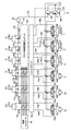
- FIG. 3 is a detailed view of a front control hydraulic unit 160 in FIG. 2; The figure which shows the coordinate system and target surface in the hydraulic shovel of FIG.
- the related figure of target surface distance Ya at the time of the 1st operation, and deceleration rate h.
- FIG. 10 is a flowchart of control (first control) by the display control unit 374a at the time of the first operation.
- FIG. 10 is a flowchart of control (first control) by the voice control unit 374b at the time of the first operation. Explanatory drawing of the notification area
- FIG. 10 is a flowchart of control (second control) by the actuator control unit 81 at the time of the second operation.
- the related figure of target surface distance Ya in the time of the 2nd operation, and deceleration rate h. 10 is a flowchart of control (second control) by the display control unit 374a at the time of the second operation. 12 is a flowchart of control (second control) by the voice control unit 374b at the time of the second operation. 10 is a flowchart of control (third control) by the actuator control unit 81 at the time of the third operation.
- 16 is a flowchart of control (third control) by the display control unit 374a at the time of the third operation. 16 is a flowchart of control (third control) by the voice control unit 374b during the third operation.
- An example of the display screen of the display apparatus 53a in case the deceleration rate h is set like FIG.
- FIG. 1 is a block diagram of a hydraulic shovel according to an embodiment of the present invention
- FIG. 2 is a view showing a controller of the hydraulic shovel according to the embodiment of the present invention together with a hydraulic drive
- FIG. It is a detail view of hydraulic control unit 160 for front control.
- the hydraulic shovel 1 is configured of an articulated work machine 1 ⁇ / b> A and a vehicle body 1 ⁇ / b> B.
- the vehicle body 1B is mounted on the lower traveling body 11 traveling by the left and right traveling hydraulic motors 3a and 3b (the hydraulic motor 3a is shown in FIG. 2) and the lower traveling body 11. It consists of 12 bodies.
- the front work implement 1A is configured by connecting a plurality of driven members (the boom 8, the arm 9, and the bucket 10) which rotate in the vertical direction.
- the proximal end of the boom 8 is rotatably supported at the front of the upper swing body 12 via a boom pin.
- An arm 9 is rotatably connected to the tip of the boom 8 via an arm pin, and a bucket 10 is rotatably connected to the tip of the arm 9 via a bucket pin.
- the boom 8 is driven by the boom cylinder 5, the arm 9 is driven by the arm cylinder 6, and the bucket 10 is driven by the bucket cylinder 7.
- the boom angle sensor 30 is for the boom pin
- the arm angle sensor 31 is for the arm pin
- the bucket angle sensor is for the bucket link 13 so that the rotation angles ⁇ , ⁇ and ⁇ (see FIG. 5) of the boom 8, arm 9 and bucket 10 can be measured.
- 32 is attached, and a vehicle body inclination angle sensor 33 for detecting an inclination angle ⁇ (see FIG. 5) of the upper structure 12 (the vehicle body 1B) with respect to a reference surface (for example, horizontal surface) is attached to the upper structure 12.
- the angle sensors 30, 31, 32 can be replaced by angle sensors with respect to a reference plane (for example, a horizontal plane).
- An operating device 47a for operating the traveling right hydraulic motor 3a (lower traveling body 11) having a traveling right lever 23a (FIG. 1) in the driver's cabin provided in the upper revolving superstructure 12;
- An operating device 47b (FIG. 2) having a left lever 23b (FIG. 1) for operating the traveling left hydraulic motor 3b (lower traveling body 11) and an operation right lever 1a (FIG. 1)
- Operating devices 45 b and 46 b (FIG. 2) for operating (the upper swing body 12) are installed.
- the travel right lever 23a, the travel left lever 23b, the operation right lever 1a, and the operation left lever 1b may be collectively referred to as operation levers 1 and 23.
- the engine 18 mounted on the upper revolving superstructure 12 drives the hydraulic pump 2 and the pilot pump 48.
- the hydraulic pump 2 is a variable displacement pump whose capacity is controlled by the regulator 2a, and the pilot pump 48 is a fixed displacement pump.
- a shuttle block 162 is provided in the middle of the pilot lines 144, 145, 146, 147, 148 and 149. Hydraulic pressure signals output from the operating devices 45, 46, 47 are also input to the regulator 2a via the shuttle block 162.
- a hydraulic pressure signal is input to the regulator 2a via the shuttle block 162, and the discharge flow rate of the hydraulic pump 2 is controlled according to the hydraulic pressure signal.
- the pump line 170 which is a discharge pipe of the pilot pump 48, passes through the lock valve 39, and then branches into a plurality of parts and is connected to the valves in the operation devices 45, 46, 47 and the hydraulic unit 160 for front control.
- the lock valve 39 is an electromagnetic switching valve in this example, and the electromagnetic drive unit is electrically connected to a position detector of a gate lock lever (not shown) disposed in the driver's cab of the upper swing body 12. The position of the gate lock lever is detected by a position detector, and a signal corresponding to the position of the gate lock lever is input to the lock valve 39 from the position detector.
- the lock valve 39 When the position of the gate lock lever is in the lock position, the lock valve 39 is closed and the pump line 170 is shut off, and when in the lock release position, the lock valve 39 is opened and the pump line 170 is opened. That is, in the state where the pump line 170 is shut off, the operation by the operating devices 45, 46, 47 is invalidated, and the operation such as turning or digging is prohibited.
- the operating devices 45, 46 and 47 are hydraulic pilot systems, and based on the pressure oil discharged from the pilot pump 48, the operating amounts (eg, lever strokes) of the operating levers 1 and 23 operated by the operator respectively A pilot pressure (sometimes referred to as operating pressure) corresponding to the operating direction is generated.
- the pilot pressure generated in this manner causes the hydraulic drive units 150a to 155b of the corresponding flow control valves 15a to 15f (see FIG. 2 or 3) in the control valve unit 20 to receive pilot lines 144a to 149b (see FIG. 3). , And used as control signals for driving the flow control valves 15a to 15f.
- the pressure oil discharged from the hydraulic pump 2 passes through the flow control valves 15a, 15b, 15c, 15d, 15e and 15f (see FIG. 3), the traveling right hydraulic motor 3a, the traveling left hydraulic motor 3b, the turning hydraulic motor 4, It is supplied to the boom cylinder 5, the arm cylinder 6, and the bucket cylinder 7.
- the boom 8, the arm 9, and the bucket 10 are respectively rotated by the expansion and contraction of the boom cylinder 5, the arm cylinder 6, and the bucket cylinder 7 by the supplied pressure oil, and the position and posture of the bucket 10 are changed.
- the swing hydraulic motor 4 is rotated by the supplied pressure oil, so that the upper swing body 12 swings relative to the lower traveling body 11.
- the traveling right hydraulic motor 3a and the traveling left hydraulic motor 3b are rotated by the supplied pressure oil, whereby the lower traveling body 11 travels.
- the posture of the work implement 1A can be defined based on the shovel reference coordinates in FIG.
- the shovel reference coordinates in FIG. 4 are the coordinates set for the upper revolving superstructure 12, with the base of the boom 8 as the origin, and the Z axis in the vertical direction in the upper revolving superstructure 12 and the X axis in the horizontal direction.
- the inclination angle of the boom 8 with respect to the X axis is the boom angle ⁇
- the inclination angle of the arm 9 with respect to the boom is the arm angle ⁇
- the inclination angle of the bucket tip with respect to the arm is the bucket angle ⁇ .
- the inclination angle of the vehicle body 1B (upper revolving unit 12) with respect to the horizontal plane (reference plane) is taken as the inclination angle ⁇ .
- the boom angle ⁇ is detected by the boom angle sensor 30, the arm angle ⁇ is detected by the arm angle sensor 31, the bucket angle ⁇ is detected by the bucket angle sensor 32, and the inclination angle ⁇ is detected by the vehicle body inclination angle sensor 33.
- the boom angle ⁇ is minimized when the boom 8 is raised to the maximum (maximum) (when the boom cylinder 5 is in the stroke end in the upward direction, ie, when the boom cylinder length is longest), and the boom 8 is minimized (minimum) It is maximum when lowered (when the boom cylinder 5 is at the stroke end in the downward direction, that is, when the boom cylinder length is the shortest).
- the arm angle ⁇ is minimum when the arm cylinder length is the shortest, and is maximum when the arm cylinder length is the longest.
- the bucket angle ⁇ is minimum when the bucket cylinder length is the shortest (in the case of FIG. 4) and is maximum when the bucket cylinder length is the longest.
- the tip position of the bucket 10 at the shovel reference coordinates is represented by the following equation with X bk as the X direction position and Z bk as the Z direction position. be able to.
- the hydraulic shovel 1 is provided with a pair of GNSS (Global Navigation Satellite System) antennas 14A and 14B on the upper swing body 12.
- GNSS Global Navigation Satellite System
- the position of the hydraulic shovel 1 in the global coordinate system and the position of the bucket 10 can be calculated based on the information from the GNSS antenna 14.
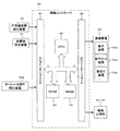
- FIG. 5 is a configuration diagram of a machine guidance (MG) and a machine control (MC) system provided in the hydraulic shovel according to the present embodiment.
- the MC of the front work machine 1A in this system is a predetermined closed area set above the target surface 700 (see FIG. 4) in which the operation devices 45a, 45b and 46a are operated and set arbitrarily.
- control for operating the work machine 1A according to predetermined conditions is executed. Specifically, in the decelerating region 600, the vector component in the direction of approaching the target surface 700 in the speed vector of the tip of the work implement 1A as the tip of the work implement 1A (for example, the tip of the bucket 10) approaches the target surface 700.
- the control of at least one of the plurality of hydraulic actuators 5, 6, 7 is performed as an MC so as to reduce the (described later in detail).
- the control of the hydraulic actuators 5, 6, 7 is performed by forcibly outputting a control signal (for example, extending the boom cylinder 5 and forcibly performing a boom raising operation) to the corresponding flow control valves 15a, 15b, 15c.
- a control signal for example, extending the boom cylinder 5 and forcibly performing a boom raising operation
- this MC prevents the tip of the bucket 10 from invading below the target surface 700, excavation along the target surface 700 becomes possible regardless of the degree of the skill of the operator.
- work implement 1A is positioned in the non-deceleration area (second area) 620 set above deceleration area 600 and adjacent to deceleration area 600, MC is not executed and the work machine is operated according to the operator's operation. 1A works.
- a dotted line 650 in FIG. 4 is a boundary between the deceleration region 600 and the non-deceleration region 620.
- the control point of the front work machine 1A at the time of MC is set to the toe of the bucket 10 of the hydraulic shovel (the tip of the work machine 1A), but the control point is the tip of the work machine 1A. If it is a point, it is changeable besides a bucket toe. For example, the bottom of the bucket 10 or the outermost part of the bucket link 13 can also be selected, and a point on the bucket 10 closest to the target surface 700 may be used as a control point.
- the controller controls the operation of the working machine 1A only when operating the operating devices 45 and 46, as opposed to “automatic control” in which the controller controls the operation of the working machine 1A by the controller when It may be called “semi-automatic control” controlled by.
- a boundary 650 between the deceleration area 600 and the non-deceleration area 620, the target surface 700, and the work machine 1A (eg, A process of displaying the positional relationship with the bucket 10) on the display device 53a is performed.
- the boundary 650 between the decelerating area 600 and the non-decelerating area 620 is displayed on the display device 53a, the positional relationship between the decelerating area 600 and the work machine 1A can be grasped by the operator.
- work machine 1A intrudes into deceleration area 600 against the intention of the operator in a phase where work machine 1A is required to perform a quick operation (for example, return operation to return the bucket to the digging start point) and work machine 1A decelerates You can control the frequency of occurrences of
- the system shown in FIG. 5 is implemented by the work machine posture detection device 50, the target surface setting device 51, the operator operation detection device 52a, the display device 53a capable of displaying the positional relationship between the target surface 700 and the work machine 1A, and MC.
- the sound output device 53b notifies that the work machine 1A is approaching to the deceleration area 600 to be done by a warning sound (voice), and the warning that it warns that the work machine 1A approaches to the deceleration area 600 using a warning light
- a light device 53b and a controller (control device) 40 that controls the MG and MC are provided.
- the work implement attitude detection device 50 is configured of a boom angle sensor 30, an arm angle sensor 31, a bucket angle sensor 32, and a vehicle body inclination angle sensor 33. These angle sensors 30, 31, 32, 33 function as posture sensors of the work machine 1A.
- the target surface setting device 51 is an interface capable of inputting information on the target surface 700 (including position information and tilt angle information of each target surface).
- the target surface setting device 51 is connected to an external terminal (not shown) which stores three-dimensional data of the target surface defined on the global coordinate system (absolute coordinate system). The operator may manually input the target surface via the target surface setting device 51.
- the operator operation detection device 52a is a pressure sensor 70a that acquires the operation pressure (first control signal) generated in the pilot lines 144, 145, 146 by the operation of the operation levers 1a, 1b (operation devices 45a, 45b, 46a) by the operator. 70b, 71a, 71b, 72a, 72b. That is, the operation on the hydraulic cylinders 5, 6, 7 related to the working machine 1A is detected.
- the display device 53a, the sound output device 53b and the warning light device 53c are installed in the driver's cab.
- these three devices 53a, 53b, 53c may be collectively referred to as the delivery device 53.
- the front control hydraulic unit 160 is provided on the pilot lines 144 a and 144 b of the operating device 45 a for the boom 8 and detects a pilot pressure (first control signal) as an operation amount of the operation lever 1 a.
- Pressure sensors 70a and 70b, an electromagnetic proportional valve 54a connected to the pilot pump 48 via the pump line 170 on the primary port side to reduce and output the pilot pressure from the pilot pump 48, and a pilot of the operating device 45a for the boom 8 Select the high pressure side of the pilot pressure in the pilot line 144a and the control pressure (second control signal) output from the solenoid proportional valve 54a, connected to the line 144a and the secondary port side of the solenoid proportional valve 54a, and select the flow control valve Of a shuttle valve 82a leading to the hydraulic drive unit 150a of 15a and an operating device 45a for the boom 8 B is installed in the lot line 144b, and a pilot pressure proportional solenoid valve 54b (the first control signal) reduces to the outputs of the pilot line 144b based on the control signal from the controller 40.
- the front control hydraulic unit 160 is installed on the pilot lines 145a and 145b for the arm 9, and detects the pilot pressure (first control signal) as an operation amount of the control lever 1b and outputs it to the controller 40 71a, 71b and a solenoid proportional valve 55b installed in the pilot line 145b and reducing and outputting the pilot pressure (first control signal) based on the control signal from the controller 40, installed in the pilot line 145a and controlled
- An electromagnetic proportional valve 55a is provided which reduces and outputs the pilot pressure (first control signal) in the pilot line 145a based on the control signal from the controller 40.
- the front control hydraulic unit 160 also detects a pilot pressure (first control signal) as an operation amount of the control lever 1a on the pilot lines 146a and 146b for the bucket 10 and outputs the pressure sensor 72a to the controller 40. , 72b, and solenoid proportional valves 56a and 56b that reduce and output the pilot pressure (first control signal) based on the control signal from the controller 40, and the primary port side is connected to the pilot pump 48 and the pilot pump 48 Select the high pressure side of the solenoid proportional valves 56c and 56d for reducing and outputting the pilot pressure, the pilot pressure in the pilot lines 146a and 146b, and the control pressure output from the solenoid proportional valves 56c and 56d, and The shuttle valves 83a and 83b leading to the hydraulic drive units 152a and 152b It is provided. In FIG. 3, connecting lines between the pressure sensors 70, 71, 72 and the controller 40 are omitted for convenience of drawing.
- the electromagnetic proportional valves 54b, 55a, 55b, 56a, 56b have the maximum opening degree when not energized, and the opening degree decreases as the current as the control signal from the controller 40 increases.
- the electromagnetic proportional valves 54a, 56c, 56d have an opening degree of zero when not energized and an opening degree when energized, and the opening degree increases as the current (control signal) from the controller 40 increases.
- the degree of opening 54, 55, 56 of each solenoid proportional valve corresponds to the control signal from the controller 40.
- the solenoid proportional valves 54a, 56c, 56d are driven by outputting a control signal from the controller 40, when there is no operator operation of the corresponding operating device 45a, 46a. Since the pilot pressure (second control signal) can also be generated, the boom raising operation, the bucket cloud operation, and the bucket dump operation can be forcibly generated. Similarly, when the solenoid proportional valves 54b, 55a, 55b, 56a and 56b are driven by the controller 40, the pilot pressure (first control signal) generated by the operator operation of the operating devices 45a, 45b and 46a is reduced. The pilot pressure (second control signal) can be generated, and the speed of the boom lowering operation, the arm cloud / dump operation, and the bucket cloud / dump operation can be forcibly reduced from the value of the operator operation.
- the pilot pressure generated by the operation of the operation devices 45a, 45b, and 46a is referred to as a "first control signal”.
- the pilot pressure generated by correcting (reducing) the first control signal by driving the solenoid proportional valves 54b, 55a, 55b, 56a, 56b by the controller 40 The pilot pressure generated by driving the solenoid proportional valves 54a, 56c, 56d by the controller 40 and newly generated separately from the first control signal is referred to as a "second control signal".
- the second control signal is generated when the velocity vector of the control point of work implement 1A generated by the first control signal violates a predetermined condition, and the velocity vector of the control point of work implement 1A which does not violate the predetermined condition Are generated as control signals for generating
- the second control signal is prioritized.
- the first control signal is interrupted by the proportional solenoid valve, and the second control signal is input to the other hydraulic drive. Therefore, of the flow control valves 15a to 15c, one for which the second control signal is calculated is controlled based on the second control signal, and one for which the second control signal is not calculated is based on the first control signal.
- the MC can also be said to control the flow control valves 15a to 15c based on the second control signal.
- the controller 40 includes an input interface 91, a central processing unit (CPU) 92 as a processor, a read only memory (ROM) 93 and a random access memory (RAM) 94 as a storage device, and an output interface 95.
- the input interface 91 receives signals from the angle sensors 30 to 32 and the tilt angle sensor 33, which are the work machine posture detection device 50, and a signal from the target surface setting device 51, which is a device for setting the target surface 700. And convert the CPU 92 so that it can operate.
- the ROM 93 is a recording medium storing a control program for executing the MG, including processing relating to a flowchart to be described later, and various information and the like necessary for executing the flowchart.
- the CPU 92 is a control program stored in the ROM 93
- the predetermined arithmetic processing is performed on the signals taken in from the input interface 91, the ROM 93, and the RAM 94 according to the above.
- the output interface 95 can operate the notification device 53 by creating a signal for output corresponding to the calculation result in the CPU 92 and outputting the signal to the delivery device 53.
- the controller 40 in FIG. 5 includes semiconductor memories such as the ROM 93 and the RAM 94 as storage devices, but any storage device can be substituted in particular.
- a magnetic storage device such as a hard disk drive may be included.
- FIG. 6 is a functional block diagram of the controller 40.
- the controller 40 includes an MG and MC controller (MG / MC controller) 43, a solenoid proportional valve controller 44, a notification controller 374 (display controller 374a, voice controller 374b, warning light controller 374c). , And an operation determination unit 66.
- FIG. 7 is a functional block diagram of the MG / MC control unit 43 in FIG.
- the MG / MC control unit 43 includes an operation amount calculation unit 43a, a posture calculation unit 43b, a target surface calculation unit 43c, an actuator control unit 81, and a target surface comparison unit 62.
- the operation amount calculator 43a calculates the amount of operation of the operation devices 45a, 45b, 46a (the operation levers 1a, 1b) based on the input from the operator operation detection device 52a. From the detection values of the pressure sensors 70, 71, 72, the amount of operation of the operating devices 45a, 45b, 46a can be calculated.
- the calculation of the operation amount by the pressure sensors 70, 71, 72 is only an example, and for example, the operation lever is detected by a position sensor (for example, a rotary encoder) that detects the rotational displacement of the operation lever of each operation device 45a, 45b, 46a.
- the amount of operation of may be detected.
- a stroke sensor that detects the expansion amount of each hydraulic cylinder 5, 6, 7 is attached, and the operation speed of each cylinder is calculated based on the detected time change of the expansion amount.
- the configuration to calculate is also applicable.
- the posture calculation unit 43b calculates the posture of the front work machine 1A in the local coordinate system (excavator reference coordinates) and the position of the tip of the bucket 10 based on the information from the work machine posture detection device 50. As described above, the toe position (Xbk, Zbk) of the bucket 10 can be calculated by the equations (1) and (2).
- the target surface calculation unit 43 c calculates the position information of the target surface 700 based on the information from the target surface setting device 51, and stores this in the RAM 94.
- a cross-sectional shape obtained by cutting a three-dimensional target surface along a plane (working plane of the working machine) along which the working machine 1A moves is used as a target plane 700 (two-dimensional target plane).
- one target surface 700 is shown in the example of FIG. 4, there may be a case where a plurality of target surfaces exist.
- a method of setting the one closest to the work machine 1A as the target surface for example, a method of setting one below the bucket toe as the target surface, or a arbitrarily selected one There is a method to make it a goal surface.
- the actuator control unit 81 controls at least one of the plurality of hydraulic actuators 5, 6, 7 in accordance with predetermined conditions when operating the operating devices 45a, 45b, 46a.
- the actuator control unit 81 according to the present embodiment controls the position of the target surface 700, the posture of the front work machine 1A, the position of the tip of the bucket 10, and the operation devices 45a, 45b, 46a when operating the operation devices 45a, 45b, 46a. Operation of at least one of the boom cylinder 5 (boom 8) and the arm cylinder 6 (arm 9) so that the toe (control point) of the bucket 10 is located on or above the target surface 700 based on the operation amount of Execute MC to control.
- the actuator control unit 81 calculates target pilot pressures of the flow control valves 15 a, 15 b and 15 c of the hydraulic cylinders 5, 6 and 7, and outputs the calculated target pilot pressure to the solenoid proportional valve control unit 44. Further, the actuator control unit 81 switches the control content of the MC according to the determination result input from the operation determination unit 66. The details of the MC by the actuator control unit 81 for each determination result of the operation determination unit 66 will be described later.
- the solenoid proportional valve control unit 44 calculates a command to each of the solenoid proportional valves 54 to 56 based on the target pilot pressure to each of the flow rate control valves 15a, 15b, 15c output from the actuator control unit 81.
- the pilot pressure (first control signal) based on the operator operation matches the target pilot pressure calculated by the actuator control unit 81, the current value (command value) to the corresponding solenoid proportional valves 54 to 56 Becomes zero, and the corresponding solenoid proportional valves 54 to 56 are not operated.
- the operation determination unit 66 determines the operation of the front work machine 1A based on the amount of operation of the operation devices 45a, 45b, 46a (the operation levers 1a, 1b) calculated by the operation amount calculation unit 43a.
- the operation determination unit 66 outputs the determination result to the actuator control unit 81 and the notification control unit 374 (display control unit 374a, voice control unit 374b, and warning light control unit 374c). Details of the operation determination flow by the operation determination unit 66 will be described later.
- the display control unit 374a receives the posture information of the front work machine 1A input from the MG / MC control unit 43, the position information of the tip of the bucket 10, the position information of the target surface 700, and the determination result input from the operation determination unit 66.
- the processing of displaying the positional relationship between the decelerating region 600 and the non-decelerating region 620 between the decelerating region 600 and the target surface 700 and the work implement 1A (the toe of the bucket 10) is displayed on the display device 53a.
- the display control unit 374a also executes a process of changing the position of the boundary 650 on the display device 53a according to the determination result of the operation determination unit 66. Details of display control by the display control unit 374a for each determination result of the operation determination unit 66 will be described later.
- the voice control unit 374b receives the posture information of the front work machine 1A input from the MG / MC control unit 43, the position information of the tip of the bucket 10, the position information of the target surface 700, and the determination result input from the operation determination unit 66. A process of controlling ON / OFF of the output of the alarm sound by the audio output device 53b is executed based on the above. Details of the audio output control by the audio control unit 374b for each determination result of the operation determination unit 66 will be described later.
- the warning light control unit 374c determines the posture information of the front working machine 1A input from the MG / MC control unit 43, the position information of the tip of the bucket 10, the position information of the target surface 700, and the determination input from the operation determination unit 66. Based on the result, processing of controlling ON (lighting) / OFF (lighting out) of the warning light by the warning light device 53c is executed. The details of lighting control by the warning light control unit 374c for each determination result of the operation determination unit 66 will be described later.
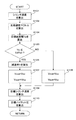
- FIG. 8 is a diagram showing an operation determination flow by the operation determination unit 66.
- the operation determination unit 66 repeats the process of FIG. 8 at a predetermined interval (control cycle).
- the operation determination unit 66 determines whether or not the arm cloud operation is input to the controller 45b in S81 (ie, whether the pressure sensor 71a detects a pressure equal to or greater than a predetermined value) ) Is determined.
- the controller 45b ie, whether the pressure sensor 71a detects a pressure equal to or greater than a predetermined value
- the determination result is output to the actuator control unit 81 and the notification control unit 374 (the display control unit 374a, the voice control unit 374b, and the warning light control unit 374c), and the operation determination unit 66 waits for the next control cycle (S82). ). On the other hand, if the input of the arm cloud operation is not detected in S81, the process proceeds to S83.
- the operation determination unit 66 determines whether an arm dump operation is input to the controller 45b (that is, whether the pressure sensor 71b detects a pressure equal to or higher than a predetermined value). Here, if the input of the arm dump operation is not detected, it is determined that the current operation is the "first operation", and the process waits for the next control cycle (S82). On the other hand, if the input of the arm dump operation is detected in S84, the process proceeds to S84.
- the operation determination unit 66 determines whether or not the boom lowering operation is input to the operation device 45a (that is, whether or not the pressure sensor 70b detects a pressure of a predetermined value or more).
- the determination result is output to the actuator control unit 81 and the notification control unit 374 (the display control unit 374a, the voice control unit 374b and the warning light control unit 374c), and the operation determination unit 66 waits for the next control cycle (S85).
- the process proceeds to S86, and it is determined that the current operation is at least the "third operation" where arm dumping (except boom lowering) is performed. Then, the determination result is output to the actuator control unit 81 and the notification control unit 374 (the display control unit 374a, the voice control unit 374b and the warning light control unit 374c), and the operation determination unit 66 waits for the next control cycle (S86) ).
- the actuator control unit 81 and the notification control unit 374 determine the determination result of the operation determination unit 66 (first operation, second operation, second 3) Execute different control depending on the operation). Next, details of the control will be described.
- FIG. 9 is a flowchart of control (first control) by the actuator control unit 81 during the first operation.
- the actuator control unit 81 starts the process of FIG. 9 when the operating devices 45a, 45b, and 46a are operated by the operator.
- the actuator control unit 81 calculates the operation speeds (cylinder speeds) of the hydraulic cylinders 5, 6, 7 based on the operation amount calculated by the operation amount calculation unit 43a.
- the actuator control unit 81 controls the bucket tip by the operator operation based on the operating speeds of the hydraulic cylinders 5, 6, 7 calculated in S101 and the posture of the work machine 1A calculated by the posture calculation unit 43b.
- the velocity vector (tip velocity vector) Vc of (toe) is calculated.
- a component horizontal to the target surface 700 in the tip velocity vector Vc is Vcx and a component vertical to the target surface 700 is Vcy.
- an XtYt coordinate system defined by the Xt axis set on the target surface 700 and the Yt axis with the normal direction of the target surface 700 as positive is set, and this XtYt is set.
- a toe velocity vector Vc, a target velocity vector Vca described later, and the like are defined.
- coordinate values of a coordinate system other than the XtYt coordinate system are converted to the XtYt coordinate system and used as needed.
- the position of the origin of the XY coordinate system shown in FIG. 11 is merely an example, and for example, the foot of a perpendicular drawn from the toe of the bucket 10 of an arbitrary posture to the target surface 700 may be used as the origin. It may be used as the origin.
- the actuator control unit 81 determines whether the component Vcy perpendicular to the target surface 700 in the tip velocity vector Vc calculated in S102 is less than zero, that is, the direction in which the tip velocity vector Vc (vertical component Vcy) approaches the target surface 700. It is determined whether or not. Here, if it is determined that the vertical component Vcy is less than zero (that is, if it is determined that the vector Vc approaches the target surface 700), the process proceeds to S104. On the other hand, if it is determined that the vertical component Vcy is greater than or equal to zero (ie, if it is determined that the vector Vc is in the direction away from the target surface 700), the process proceeds to S108.
- the actuator control unit 81 determines from the bucket tip to the target surface 700 from the position (coordinates) of the tip of the bucket 10 calculated by the posture calculation unit 43b and the straight line including the target surface 700 stored in the ROM 93.
- the distance Ya (see FIG. 4) is calculated, and the process proceeds to S105.
- the actuator control unit 81 determines whether the target surface distance Ya calculated in S104 is equal to or less than Ya1.
- Ya1 is the distance from the target surface 700 to the boundary 650 during the first operation, and is the height of the deceleration region 600 during the first operation. Therefore, the fact that the target surface distance Ya is equal to or less than Ya1 indicates that the toe is present in the deceleration region 600, and the fact that Ya1 is exceeded indicates that the toe is present in the non-deceleration region 620.
- the value of Ya1 may differ depending on the determination result by the operation determination unit 66. If Ya is less than Ya1 in S104, the process proceeds to S106, and if greater than Ya1, the process proceeds to S108.
- the actuator control unit 81 calculates the deceleration rate h of the component Vcy perpendicular to the target surface 700 in the speed vector of the bucket tip based on Ya calculated in S104 and the graph of FIG.
- the deceleration rate h is a value of 0 or more and 1 or less set in advance for each target surface distance Ya.
- the target surface distance Ya is maintained at 1 in the range exceeding the predetermined value Ya1, and in the range where the target surface distance Ya is less than Ya1, the deceleration ratio h decreases as the distance Ya decreases. It is set to In the example of FIG.
- the deceleration rate h decreases linearly as the target plane distance Ya decreases, but if the deceleration rate h decreases from 1 to zero as the target plane distance Ya decreases, it will be described later Various modifications are possible including FIGS. 18 and 23 which define the deceleration rate h in the second control and the third control. After calculating the deceleration rate h, the actuator control unit 81 proceeds to S107.
- the process proceeds to S109.
- the actuator control unit 81 calculates the target speeds of the hydraulic cylinders 5, 6, 7 based on the target speed vector Vca (Vcxa, Vcya) determined in S107 or S108. At this time, if the software is designed to perform MC for converting the tip speed vector Vc into the target speed vector Vca by a combination of boom raising and deceleration of the arm cloud, the cylinder speed of the boom cylinder 5 in the extension direction and the arm The cylinder speed in the extension direction of the cylinder 6 is calculated.
- the actuator control unit 81 determines the target pilot pressure to the flow control valves 15a, 15b, 15c of the hydraulic cylinders 5, 6, 7 based on the target speeds of the cylinders 5, 6, 7 calculated in S109.
- the target pilot pressure to the flow control valves 15a, 15b, 15c of the hydraulic cylinders 5, 6, 7 is calculated and output to the solenoid proportional valve control unit 44.
- the solenoid proportional valve control unit 44 controls the solenoid proportional valves 54, 55, and 56 such that the target pilot pressure acts on the flow control valves 15a, 15b, and 15c of the hydraulic cylinders 5, 6, and 7, and thereby the work machine Drilling by 1A is performed.
- the proportional solenoid valve 55c is controlled so that the tip of the bucket 10 does not enter the target surface 700, and the raising operation of the boom 8 And the deceleration operation of the arm cloud is performed automatically.
- FIG. 11 is a diagram showing an example of a locus when the tip of the bucket 10 is MCed as the corrected target velocity vector Vca as described above.
- the parallel component Vcx becomes constant, and the vertical component Vcy becomes smaller as the tip of the bucket 10 approaches the target surface 700 (as the distance Ya becomes smaller).
- the corrected target velocity vector Vca is a composite, the locus becomes a curve that becomes parallel as it approaches the target surface 700 as shown in FIG.
- MC is not limited to the automatic control of the boom raising operation and the deceleration operation of the arm cloud described, for example, the bucket 10 is automatically rotated, and the target surface 700 and the bottom of the bucket 10 Control may be performed to keep the angle formed by the constant.
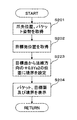
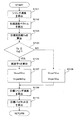
- FIG. 12 is a flowchart of control (first control) by the display control unit 374a during the first operation.
- the display control unit 374a starts the process of FIG. 12 at a predetermined control cycle.
- the display control unit 374a acquires the toe position and the posture of the bucket 10 from the posture calculation unit 43b.
- the display control unit 374a acquires position information of the target surface 700 from the target surface calculation unit 43c.
- the display control unit 374a sets the position of the boundary line 650 at the position of + Ya1 in the normal direction of the target surface 700 from the position of the target surface 700 acquired in S202.
- the target surface 700 is offset by Ya1 in the positive direction along the Yt axis.
- the offset amount Ya1 matches the value (Ya1) used by the actuator control unit 81 in the determination of S105, and may change in accordance with the determination result of the operation determination unit 66.
- the display control unit 374a displays the positional relationship between the boundary line 650, the target surface 700, and the bucket 10 on the screen of the display device 53a based on the information acquired in S201, S202, and S203.
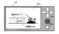
- FIG. 13 is a view showing an example of the configuration of the delivery device 53.
- the notification device 53 shown in this figure includes a display device 53a, an audio output device 53b, and a warning light device 53c.
- the positional relationship between the boundary line 650, the target surface 700, and the bucket 10 is displayed on the display screen of the display device 53a.
- the distance between the target surface 700 and the boundary 650 in this case is Ya1 [m].
- the operator grasps the positional relationship between the bucket 10 displayed on the display device 53a and the deceleration area 600 and returns. Since the work implement 1A can return while passing through the decelerating area 600 in which the machine control is performed, the work efficiency can be improved.
- FIG. 14 is a flowchart of control (first control) by the voice control unit 374b during the first operation.
- the voice control unit 374b starts the process of FIG. 14 at a predetermined control cycle.
- step S301 the voice control unit 374b determines the distance from the tip of the bucket to the target surface 700 based on the position (coordinates) of the tip of the bucket 10 calculated by the posture calculation unit 43b and the straight line including the target surface 700 stored in the ROM 93.
- the distance Ya (see FIG. 4) is calculated, and the process proceeds to S302.
- the voice control unit 374b determines whether the target surface distance Ya calculated in S301 is equal to or less than the height Ya1 of the deceleration area 600 plus the height Yc1 of the notification area 640 (see FIG. 15). judge.
- FIG. 15 is an explanatory diagram of the notification area 640.
- the notification area 640 is an area of the height Yc 1 set adjacent to the upper side of the deceleration area 600.
- Yc1 is also an offset amount above the boundary line 650.
- a sound is generated to notify the operator that the tip of the bucket 10 is likely to infiltrate the deceleration area 600. If it is determined in S302 that the target surface distance Ya is equal to or less than Ya1 + Yc1, the process proceeds to S303, and if it exceeds Ya1 + Yc1, the process proceeds to S304.
- the voice control unit 374b sounds an alarm from the voice output device 53b (see FIG. 6).
- the voice control unit 374b waits for the next control start time without producing an alarm sound from the voice output device 53b.
- the operator can recognize that the tip of the bucket 10 is likely to intrude into the deceleration area 600.
- the working machine 1A can be efficiently steered so that the tip of the bucket 10 does not intrude into the deceleration area 600.
- the warning light control unit 374c When the warning light control unit 374c is configured as described above, the warning light 53c (see FIG. 13) is turned on when the tip of the bucket 10 intrudes into the notification area 640. Can recognize that it is likely to invade. Thus, the working machine 1A can be efficiently steered so that the tip of the bucket 10 does not intrude into the deceleration area 600.
- FIG. 16 is a flowchart of control (second control) by the actuator control unit 81 at the time of the second operation.
- the same steps as in the flow of the first operation shown in FIG. 9 are assigned the same reference numerals and descriptions thereof will be omitted, and the same applies to the following figures.
- the actuator control unit 81 determines whether the target surface distance Ya calculated in S104 is equal to or less than 0.8 Ya2.
- 0.8Ya2 is the distance from the target surface 700 to the boundary 650 during the second operation, and is the height of the deceleration region 600 during the second operation. Also, the value of 0.8Ya2 may differ depending on the determination result by the operation determination unit 66. If Ya is equal to or less than 0.8 Ya2 in S104, the process proceeds to S126, and if greater than 0.8 Ya2, the process proceeds to S108.
- the actuator control unit 81 calculates the deceleration rate h of the component Vcy perpendicular to the target surface 700 in the speed vector of the bucket tip based on Ya calculated in S104 and the graph of FIG.
- FIGS. 17 and 18 are diagrams showing the relationship between the target surface distance Ya and the deceleration rate h during the second operation.
- FIG. 17 shows a part of FIG. 18 rewritten in the form of a table.
- the target surface distance Ya is maintained at 1 in the range exceeding the predetermined value 0.8Ya2, and in the range where the target surface distance Ya is 0.8Ya2 or less, deceleration is performed as the distance Ya decreases.
- the rate h is also set to decrease. In the example of FIG.
- the deceleration rate h decreases in a curved manner as the target surface distance Ya decreases, and the deceleration starts from a position where the target surface distance Ya is smaller than in the case of the third operation of FIG.
- This enables more efficient return operation by preventing the speed vector from decelerating within the range where the target surface distance Ya exceeds 0.8Ya2 at the time of arm dump + boom lowering (during second operation) It is for.
- the relationship between the target surface distance Ya and the deceleration ratio h can be variously changed as long as the deceleration ratio h decreases from 1 to zero as the target surface distance Ya decreases.
- Ya2 may be matched with Ya1.
- the height 0.8Ya2 of the boundary line 650 from the target surface 700 is also commonly used by the notification control unit 374 in the second operation.
- FIG. 19 is a flowchart of control (second control) by the display control unit 374a during the second operation.
- the display control unit 374a sets the position of the boundary 650 at a position of +0.8 Ya2 in the normal direction of the target surface 700 from the position of the target surface 700 acquired in S202.
- the target surface 700 is offset by 0.8 Ya2 in the positive direction on the Yt axis.
- the offset amount 0.8Ya2 matches the value (0.8Ya2) used by the actuator control unit 81 in the determination of S125, and may change according to the determination result of the operation determination unit 66.
- FIG. 26 is a view showing an example of the notification device 53 in the second operation.
- the positional relationship between the boundary line 650, the target surface 700, and the bucket 10 is displayed on the display screen of the display device 53a.
- the distance between the target surface 700 and the boundary 650 in this case is 0.8 Ya 2 [m].
- the operator can use the bucket 10 even if the position of the boundary line 650 changes according to the operation (operation) of the front work machine 1A. Since the return operation can be performed while grasping the positional relationship between the speed reduction area 600 and the speed reduction area 600, the time for the work machine 1A to return while passing through the reduction speed area 600 where machine control is executed can be reduced and work efficiency can be improved. .
- FIG. 20 is a flowchart of control (second control) by the voice control unit 374b during the second operation.
- the voice control unit 374b determines whether the target surface distance Ya calculated in S301 is equal to or less than the height 0.8 Ya2 of the deceleration area 600 plus the height Yc1 of the notification area 640. If it is determined in S322 that the target surface distance Ya is equal to or less than 0.8Ya2 + Yc1, the process proceeds to S303. If it exceeds 0.8Ya2 + Yc1, the process proceeds to S304.
- FIG. 21 is a flowchart of control (third control) by the actuator control unit 81 during the third operation.
- the actuator control unit 81 determines whether the target surface distance Ya calculated in S104 is equal to or less than Ya2.
- Ya2 is the distance from the target surface 700 to the boundary 650 during the third operation, and the height of the deceleration region 600 during the third operation.
- the value of Ya2 may differ depending on the determination result by the operation determination unit 66. If Ya is equal to or less than Ya2 in S104, the process proceeds to S136, and if Y2 is greater than Ya2, the process proceeds to S108.
- the actuator control unit 81 calculates the deceleration rate h of the component Vcy perpendicular to the target surface 700 in the velocity vector of the bucket tip based on Ya calculated in S104 and the graph of FIG. 22 and 23 are diagrams showing the relationship between the target surface distance Ya and the deceleration rate h during the third operation.
- FIG. 22 shows a part of FIG. 23 rewritten in the form of a table.
- the target surface distance Ya is maintained at 1 in the range exceeding the predetermined value Ya2, and the deceleration ratio h decreases as the distance Ya decreases in the range where the target surface distance Ya is less than Ya2. It is set to In the example of FIG.
- the deceleration ratio h decreases linearly with the decrease of the target surface distance Ya, and the deceleration starts from the position where the target surface distance Ya is larger than in the case of the second operation of FIG. This is to decelerate the velocity vector from where the target surface distance Ya is large in order to prevent the bucket front end and the rear end from invading the target surface 700 by the arm dump operation during the first return operation described later.
- the relationship between the target surface distance Ya and the deceleration ratio h can be variously changed as long as the deceleration ratio h decreases from 1 to zero as the target surface distance Ya decreases.
- Ya2 may be matched with Ya1.
- the height Ya2 of the boundary line 650 from the target surface 700 is also commonly used by the notification control unit 374 in the third operation.
- FIG. 24 is a flowchart of control (third control) by the display control unit 374a during the third operation.
- the display control unit 374a sets the position of the boundary 650 at the position of + Ya2 in the normal direction of the target surface 700 from the position of the target surface 700 acquired in S202.
- the target surface 700 is offset by Ya2 in the positive direction along the Yt axis.
- the offset amount Ya2 matches the value (Ya2) used by the actuator control unit 81 in the determination of S135, and may change according to the determination result of the operation determination unit 66.
- FIG. 27 is a view showing an example of the notification device 53 in the third operation.
- the positional relationship between the boundary line 650, the target surface 700, and the bucket 10 is displayed on the display screen of the display device 53a.
- the distance between the target plane 700 and the boundary 650 in this case is Ya2 [m].
- the operator can use the bucket 10 even if the position of the boundary line 650 changes according to the operation (operation) of the front work machine 1A. Since the return operation can be performed while grasping the positional relationship between the speed reduction area 600 and the speed reduction area 600, the time for the work machine 1A to return while passing through the reduction speed area 600 where machine control is executed can be reduced and work efficiency can be improved. .
- FIG. 25 is a flowchart of control (third control) by the voice control unit 374b during the third operation.
- the voice control unit 374b determines whether the target surface distance Ya calculated in S301 is equal to or less than the height Ya2 of the deceleration area 600 plus the height Yc1 of the notification area 640. If it is determined in S332 that the target surface distance Ya is equal to or less than Ya2 + Yc1, the process proceeds to S303, and if Ya2 + Yc1 is exceeded, the process proceeds to S304.
- the actuator controller 81 moves the vertical component of the velocity vector of the toe to the target surface 700 (the target surface 700).
- MC is executed to control at least one of the hydraulic actuators 5, 6, 7 so that the vertical component is reduced.
- the toe of the bucket 10 moves out of the deceleration area 600 and moves to the non-deceleration area 620 during this first return operation. Then, from the viewpoint of improving the working efficiency, it is preferable to move the bucket 10 forward of the vehicle body 1B so as not to enter the deceleration region 600 again after leaving the deceleration region 600 with a route as short as possible.
- the positional relationship between the toe of the bucket 10, the target surface 700, and the boundary 650 is displayed on the display screen of the display device 53a according to the flow of FIG. Always displayed.
- the height (Ya2) of the boundary 650 in the first return operation (third operation) is set higher than the height (0.8 Ya2) in the second return operation (second operation).
- an alarm by the voice control unit 374 b when the bucket 10 enters the notification area 640 The sound output and the lighting of the warning light by the warning light control unit 374c are performed. That is, in the present embodiment, the operator can notice the fact before the bucket 10 enters the deceleration area 600 by the alarm sound and the warning light, so even if the operator takes his eyes off the display screen It is possible to prevent the speed reduction area 600 from invading again during the return operation.
- Second return work (boom lowering operation, arm dumping operation)
- the operator inputs a combined operation of the arm dump operation and the boom lowering operation through the operating devices 45a and 45b or the boom lowering operation alone is performed through the operating device 45a.
- the bucket 10 is moved to the digging start position again by inputting.
- the operation determination unit 66 of the controller 40 determines the “second operation” based on the flow of FIG. It outputs to the part 81 and the notification control part 374.
- the actuator control unit 81 starts the flow of FIG. 16
- the display control unit 374a starts the flow of FIG. 19
- the voice control unit 374b starts the flow of FIG. 20 (although the warning light control unit 374c will not be described for convenience).
- the boundary line 650 between the decelerating region 600 and the non-decelerating region 620 is set at a position of +0.8 Ya2 [m] from the target surface 700.
- the toe of the bucket 10 is moved again from the non-decelerating area 620 to the decelerating area 600 during this second return operation. If the timing of the boom lowering operation is too early, the time during which the bucket 10 is present in the deceleration region 600 may be prolonged, and the working efficiency may be reduced. In addition, even if the time existing in the deceleration region 600 can be shortened by delaying the timing of the boom lowering operation (for example, by performing the boom lowering alone operation after the arm dump sole operation), the timing of the boom lowering operation is delayed. If it is too long, the time of the second return work itself may be prolonged, and the work efficiency may be reduced.
- the height of the boundary line 650 (0.
- a more efficient return operation can be performed by setting 8Ya2) lower than the height (Ya2) in the first return operation (third operation) to create a situation in which the bucket 10 can be brought relatively close to the ground surface It is like that. Further, since the reduction rate of the deceleration rate h is set smaller than the first return operation (third operation), the deceleration of the bucket after entering the deceleration region 600 is small, and the bucket 10 can be easily brought close to the ground surface. ing.
- the positional relationship between the tip of the bucket 10, the target surface 700, and the boundary 650 is always displayed on the display screen of the display device 53a.
- the operator can operate the front work device 1A while confirming on the display screen whether the lowering operation should be input.
- an alarm sound and a warning that are output and lit when the bucket 10 intrudes into the notification area 640 Since the light makes it possible for the operator to notice that the bucket 10 is approaching the deceleration area 600, it is possible to prevent the bucket 10 from entering the deceleration area 600 at a timing not intended by the operator.
- the position of the boundary 650 between the decelerating region 600 and the non-decelerating region 620 according to the operation of the front work device 1A (the height of the boundary 650 based on the target surface 700) Is configured to change.
- the position of the boundary line 650 is Ya1 [m], Ya2 Although it changes in the order of [m] and 0.8Ya 2 [m], it is very difficult to grasp the change accurately only by the operator's sense.
- the position of the boundary 650 on the display screen is also changed in accordance with the position change of the boundary 650 accompanied by the operator operation (the operation of the work machine 1A). You can easily grasp the change.
- the position of the demarcation line 650 between the decelerating area 600 where MC is executed and the non-decelerating area 620 where MC is not executed is displayed on the display device 53a together with the position of the bucket 10.
- the operator can operate the front work machine 1A with reference to the display screen, thereby reducing the time for the front work machine 1A to pass through the deceleration area 600 where the MC is executed at a timing not intended by the operator Work efficiency can be improved.
- the present invention is not limited to the above-described embodiment, and includes various modifications within the scope of the present invention.
- the present invention is not limited to the one provided with all the configurations described in the above embodiment, but also includes one in which a part of the configuration is deleted.
- part of the configuration according to one embodiment can be added to or replaced with the configuration according to another embodiment.
- the notification form by the notification device 53 according to the present invention can be variously modified in addition to those described above.
- the display control device 374a is configured to express the degree to which the vertical component of the tip velocity vector of the work machine 1A is decelerated as it approaches the target surface 700 in the deceleration region 600. You may.
- FIG. 28 shows an example in which the deceleration rate h is expressed in color in the deceleration area 600 on the screen of the display device 53a, and is displayed so that the color becomes darker as the deceleration rate h approaches zero.
- the operation efficiency can be improved by performing an operation of causing the bucket 10 to pass an area where the deceleration rate is as close to 1 as possible.
- the height of the boundary line 650 according to the target surface shape as shown in FIG. May be changed.
- the portion closer to the intersection of the two target surfaces is set such that the height of the boundary 650 from the target surface 700 is higher than the other portions. If the change in height of the boundary 650 is not uniform as shown in FIG. 29 and the operator can not predict intuitively, the merit of displaying the boundary 650 as in the present invention is further increased.
- the deceleration rate h may be changed in consideration of (the distance from the intersection of two target surfaces). For example, in the example of FIG. 29, the portion where the distance from the intersection of the two target surfaces is close is set so that the deceleration rate is smaller even if the distance from the target surface 700 is greater than the other portions. As shown in FIG. 29, when the change in the deceleration ratio h in the deceleration region 600 is not uniform and intuitive prediction by the operator is difficult, the merit of expressing the deceleration ratio h in color as shown in FIG. 28 is further increased. Do.
- FIG. 30 shows an example of the display screen of the display device 53a when the deceleration rate h is set as shown in FIG.
- the shape of the boundary 650 between the decelerating area 600 and the non-decelerating area 620 may be other than a straight line.
- the alarm sounds outputted in the notification area 640 and the deceleration area 600 are different so that the operator can recognize which of the notification area 640 and the deceleration area 600 the toe is in. Also good.
- the alarm sound output in the notification area 640 may change the sound cycle according to the distance from the boundary 650 to the toe.
- the period of sound may be shortened in a region where the distance is short, and the period of sound may be long in a region where the distance is long.
- the alarm sound output in the deceleration area 600 may change the sound cycle according to the deceleration rate h.
- the period of the sound may be shortened in a region where the deceleration rate h is strong (a region close to 0) and the period of the sound may be long in a region where the deceleration rate h is weak (a region close to 1).
- the tip of the bucket 10 can be operated so as to pass through the area where the deceleration rate h is weak by listening to the sound. Efficiency can be improved.
- the alarm sound may be emitted only in the notification area 640, and the alarm sound may not be emitted in the deceleration area 600.
- the alarm sound may be voice.
- each configuration of the controller 40 described above, the function of each configuration, execution processing, etc. are realized partially or entirely by hardware (for example, designing logic for executing each function by an integrated circuit, etc.) You may.
- the configuration according to the controller 40 may be a program (software) in which each function according to the configuration of the control device is realized by being read and executed by an arithmetic processing unit (for example, a CPU).
- the information related to the program can be stored in, for example, a semiconductor memory (flash memory, SSD, etc.), a magnetic storage device (hard disk drive, etc.), a recording medium (magnetic disk, optical disc, etc.), and the like.
- control line and the information line showed what was understood to be required for description of the said embodiment in the description of each said embodiment, all the control lines and information lines which concern on a product are not necessarily shown. Does not necessarily indicate. In practice, it can be considered that almost all configurations are mutually connected.
- operation determination unit 81 ... actuator control unit, 374 ... notification control unit, 374a ... display control unit, 374b ... voice control unit, 374c ... warning Controller, 600 ... deceleration region (first region), 620 ... non-reduction region (second region), 640 ... notification area, 650 ... boundary, 700 ... target surface
Landscapes
- Engineering & Computer Science (AREA)
- Mining & Mineral Resources (AREA)
- Civil Engineering (AREA)
- General Engineering & Computer Science (AREA)
- Structural Engineering (AREA)
- Mechanical Engineering (AREA)
- Operation Control Of Excavators (AREA)
- Component Parts Of Construction Machinery (AREA)
Abstract
Une pelle hydraulique comprend un dispositif de commande pourvu d'une unité de commande d'actionneur qui exécute une commande d'engin pour actionner un engin de chantier en fonction d'une condition prédéterminée lorsque l'engin de chantier est situé dans une région de décélération et n'exécute pas la commande lorsque l'engin de chantier est situé dans une région de non-décélération. Le dispositif de commande comprend en outre : une unité de détermination de fonctionnement qui détermine le fonctionnement de l'engin de chantier sur la base de la variable manipulée d'un manipulateur; et une unité de commande d'affichage qui affiche une ligne de délimitation entre la région de décélération et la région de non-décélération, un plan cible et la relation de position de l'engin de chantier sur un dispositif d'affichage. L'unité de commande d'actionneur modifie la position de la ligne de délimitation en fonction du résultat de détermination de l'unité de détermination de fonctionnement et exécute une commande d'engin, et l'unité de commande d'affichage change la position d'affichage de la ligne de délimitation sur le dispositif d'affichage conformément au résultat de détermination de l'unité de détermination de fonctionnement.
Priority Applications (4)
| Application Number | Priority Date | Filing Date | Title |
|---|---|---|---|
| US16/645,502 US11479941B2 (en) | 2017-12-22 | 2018-12-20 | Work machine |
| CN201880054844.0A CN111032963B (zh) | 2017-12-22 | 2018-12-20 | 作业机械 |
| EP18891901.3A EP3730699B1 (fr) | 2017-12-22 | 2018-12-20 | Engin de chantier |
| KR1020207004800A KR102314498B1 (ko) | 2017-12-22 | 2018-12-20 | 작업 기계 |
Applications Claiming Priority (2)
| Application Number | Priority Date | Filing Date | Title |
|---|---|---|---|
| JP2017246929A JP6752193B2 (ja) | 2017-12-22 | 2017-12-22 | 作業機械 |
| JP2017-246929 | 2017-12-22 |
Publications (1)
| Publication Number | Publication Date |
|---|---|
| WO2019124520A1 true WO2019124520A1 (fr) | 2019-06-27 |
Family
ID=66994213
Family Applications (1)
| Application Number | Title | Priority Date | Filing Date |
|---|---|---|---|
| PCT/JP2018/047091 Ceased WO2019124520A1 (fr) | 2017-12-22 | 2018-12-20 | Engin de chantier |
Country Status (6)
| Country | Link |
|---|---|
| US (1) | US11479941B2 (fr) |
| EP (1) | EP3730699B1 (fr) |
| JP (1) | JP6752193B2 (fr) |
| KR (1) | KR102314498B1 (fr) |
| CN (1) | CN111032963B (fr) |
| WO (1) | WO2019124520A1 (fr) |
Cited By (2)
| Publication number | Priority date | Publication date | Assignee | Title |
|---|---|---|---|---|
| JP2021055360A (ja) * | 2019-09-30 | 2021-04-08 | 日立建機株式会社 | 作業機械 |
| US11970792B2 (en) | 2021-06-16 | 2024-04-30 | Pedax Gmbh | Apparatus for manufacturing reinforcement meshes and a spinning station therefor |
Families Citing this family (11)
| Publication number | Priority date | Publication date | Assignee | Title |
|---|---|---|---|---|
| KR102685684B1 (ko) * | 2018-11-14 | 2024-07-15 | 스미도모쥬기가이고교 가부시키가이샤 | 쇼벨, 쇼벨의 제어장치 |
| JP7096425B2 (ja) * | 2019-03-27 | 2022-07-05 | 日立建機株式会社 | 作業機械 |
| JP7269143B2 (ja) * | 2019-09-26 | 2023-05-08 | 日立建機株式会社 | 作業機械 |
| US11421402B2 (en) * | 2020-02-05 | 2022-08-23 | Caterpillar Paving Products Inc. | Operation-based object detection for a work machine |
| JP7401370B2 (ja) * | 2020-03-24 | 2023-12-19 | 日立建機株式会社 | 作業機械 |
| CN116348644B (zh) * | 2020-10-19 | 2025-12-19 | 日立建机株式会社 | 作业机械 |
| US20220267993A1 (en) * | 2021-02-25 | 2022-08-25 | Deere & Company | Apparatus and method for limiting movement of a work machine |
| US12110660B2 (en) * | 2022-02-24 | 2024-10-08 | Caterpillar Inc. | Work machine 3D exclusion zone |
| JP2024092244A (ja) * | 2022-12-26 | 2024-07-08 | 住友重機械工業株式会社 | ショベル、ショベルの操作システム |
| JP2025010677A (ja) * | 2023-07-10 | 2025-01-23 | コベルコ建機株式会社 | 作業機械 |
| KR102842887B1 (ko) | 2024-05-08 | 2025-08-06 | 주식회사 아쿠아티카 | 의류 제조 방법 |
Citations (4)
| Publication number | Priority date | Publication date | Assignee | Title |
|---|---|---|---|---|
| WO1995030059A1 (fr) | 1994-04-28 | 1995-11-09 | Hitachi Construction Machinery Co., Ltd. | Dispositif de commande d'excavation a limitation de surface de travail pour engin de terrassement |
| JP2004068433A (ja) * | 2002-08-07 | 2004-03-04 | Hitachi Constr Mach Co Ltd | 掘削機械の表示システム及びそのプログラム |
| JP2013217138A (ja) * | 2012-04-11 | 2013-10-24 | Komatsu Ltd | 油圧ショベルの掘削制御システム |
| WO2016148251A1 (fr) | 2015-03-19 | 2016-09-22 | 住友建機株式会社 | Excavateur |
Family Cites Families (13)
| Publication number | Priority date | Publication date | Assignee | Title |
|---|---|---|---|---|
| JP3455359B2 (ja) * | 1996-03-21 | 2003-10-14 | 日立建機株式会社 | 建設機械の作業範囲制限制御装置 |
| JP3811190B2 (ja) | 1997-06-20 | 2006-08-16 | 日立建機株式会社 | 建設機械の領域制限掘削制御装置 |
| JP4734214B2 (ja) | 2006-10-23 | 2011-07-27 | 日立建機株式会社 | 油圧ショベルのフロント位置合わせ制御装置 |
| CN103348063B (zh) * | 2011-03-24 | 2015-12-09 | 株式会社小松制作所 | 工作装置控制系统、建筑机械及工作装置控制方法 |
| JP5624108B2 (ja) | 2012-11-14 | 2014-11-12 | 株式会社小松製作所 | 掘削機械の表示システム及び掘削機械 |
| JP5789279B2 (ja) * | 2013-04-10 | 2015-10-07 | 株式会社小松製作所 | 掘削機械の施工管理装置、油圧ショベルの施工管理装置、掘削機械及び施工管理システム |
| KR101729050B1 (ko) * | 2013-04-12 | 2017-05-02 | 가부시키가이샤 고마쓰 세이사쿠쇼 | 건설 기계의 제어 시스템 및 제어 방법 |
| DE112014000083B4 (de) | 2014-05-15 | 2018-04-05 | Komatsu Ltd. | Anzeigesystem für Baggermaschine und Anzeigeverfahren für Baggermaschine |
| KR102488448B1 (ko) * | 2015-03-27 | 2023-01-12 | 스미토모 겐키 가부시키가이샤 | 쇼벨 |
| KR102476122B1 (ko) | 2015-03-27 | 2022-12-08 | 스미토모 겐키 가부시키가이샤 | 쇼벨 |
| US9617717B2 (en) * | 2015-06-29 | 2017-04-11 | Komatsu Ltd. | Construction machine control system and construction machine control method |
| JP2017110472A (ja) | 2015-12-18 | 2017-06-22 | 住友建機株式会社 | ショベル |
| KR102298318B1 (ko) | 2016-03-30 | 2021-09-03 | 스미토모 겐키 가부시키가이샤 | 쇼벨 및 쇼벨의 표시장치 |
-
2017
- 2017-12-22 JP JP2017246929A patent/JP6752193B2/ja active Active
-
2018
- 2018-12-20 EP EP18891901.3A patent/EP3730699B1/fr active Active
- 2018-12-20 CN CN201880054844.0A patent/CN111032963B/zh not_active Expired - Fee Related
- 2018-12-20 KR KR1020207004800A patent/KR102314498B1/ko not_active Expired - Fee Related
- 2018-12-20 US US16/645,502 patent/US11479941B2/en active Active
- 2018-12-20 WO PCT/JP2018/047091 patent/WO2019124520A1/fr not_active Ceased
Patent Citations (4)
| Publication number | Priority date | Publication date | Assignee | Title |
|---|---|---|---|---|
| WO1995030059A1 (fr) | 1994-04-28 | 1995-11-09 | Hitachi Construction Machinery Co., Ltd. | Dispositif de commande d'excavation a limitation de surface de travail pour engin de terrassement |
| JP2004068433A (ja) * | 2002-08-07 | 2004-03-04 | Hitachi Constr Mach Co Ltd | 掘削機械の表示システム及びそのプログラム |
| JP2013217138A (ja) * | 2012-04-11 | 2013-10-24 | Komatsu Ltd | 油圧ショベルの掘削制御システム |
| WO2016148251A1 (fr) | 2015-03-19 | 2016-09-22 | 住友建機株式会社 | Excavateur |
Non-Patent Citations (1)
| Title |
|---|
| See also references of EP3730699A4 |
Cited By (6)
| Publication number | Priority date | Publication date | Assignee | Title |
|---|---|---|---|---|
| JP2021055360A (ja) * | 2019-09-30 | 2021-04-08 | 日立建機株式会社 | 作業機械 |
| WO2021065813A1 (fr) * | 2019-09-30 | 2021-04-08 | 日立建機株式会社 | Engin de chantier |
| CN113518843A (zh) * | 2019-09-30 | 2021-10-19 | 日立建机株式会社 | 作业机械 |
| JP7245141B2 (ja) | 2019-09-30 | 2023-03-23 | 日立建機株式会社 | 油圧ショベル |
| US12241236B2 (en) | 2019-09-30 | 2025-03-04 | Hitachi Construction Machinery Co., Ltd. | Work machine including a boom, an arm and a bucket, and for performing work including finishing and rough excavation of a flat surface or an inclined surface of a construction target |
| US11970792B2 (en) | 2021-06-16 | 2024-04-30 | Pedax Gmbh | Apparatus for manufacturing reinforcement meshes and a spinning station therefor |
Also Published As
| Publication number | Publication date |
|---|---|
| KR102314498B1 (ko) | 2021-10-19 |
| US20200277752A1 (en) | 2020-09-03 |
| KR20200033900A (ko) | 2020-03-30 |
| CN111032963A (zh) | 2020-04-17 |
| EP3730699A1 (fr) | 2020-10-28 |
| JP6752193B2 (ja) | 2020-09-09 |
| JP2019112825A (ja) | 2019-07-11 |
| EP3730699B1 (fr) | 2023-04-26 |
| CN111032963B (zh) | 2022-02-25 |
| EP3730699A4 (fr) | 2021-11-03 |
| US11479941B2 (en) | 2022-10-25 |
Similar Documents
| Publication | Publication Date | Title |
|---|---|---|
| JP6752193B2 (ja) | 作業機械 | |
| CN108699802B (zh) | 作业机械 | |
| KR102399329B1 (ko) | 작업 기계 | |
| JP6526321B2 (ja) | 作業機械 | |
| KR102154581B1 (ko) | 작업 기계 | |
| CN109983182B (zh) | 作业机械 | |
| KR102118386B1 (ko) | 작업 기계 | |
| CN111032969B (zh) | 作业机械 | |
| WO2014167718A1 (fr) | Système de commande et procédé de commande pour machine de construction | |
| CN114829710A (zh) | 挖土机、远程操作支援装置 | |
| WO2022201905A1 (fr) | Engin de chantier | |
| CN111492111B (zh) | 挖土机 | |
| JP7478280B1 (ja) | 作業機械 | |
| US20250207353A1 (en) | Work vehicle | |
| JP7036868B2 (ja) | 作業機械の制御装置及び制御方法 | |
| JP2026050042A (ja) | 建設機械のための建設機械制御装置及び建設機械 |
Legal Events
| Date | Code | Title | Description |
|---|---|---|---|
| 121 | Ep: the epo has been informed by wipo that ep was designated in this application |
Ref document number: 18891901 Country of ref document: EP Kind code of ref document: A1 |
|
| ENP | Entry into the national phase |
Ref document number: 20207004800 Country of ref document: KR Kind code of ref document: A |
|
| NENP | Non-entry into the national phase |
Ref country code: DE |
|
| ENP | Entry into the national phase |
Ref document number: 2018891901 Country of ref document: EP Effective date: 20200722 |