WO2019127561A1 - Dispositif de traitement de déchets liquides, procédé et analyseur d'échantillons - Google Patents
Dispositif de traitement de déchets liquides, procédé et analyseur d'échantillons Download PDFInfo
- Publication number
- WO2019127561A1 WO2019127561A1 PCT/CN2017/120372 CN2017120372W WO2019127561A1 WO 2019127561 A1 WO2019127561 A1 WO 2019127561A1 CN 2017120372 W CN2017120372 W CN 2017120372W WO 2019127561 A1 WO2019127561 A1 WO 2019127561A1
- Authority
- WO
- WIPO (PCT)
- Prior art keywords
- waste liquid
- pool
- waste
- pressure
- liquid pool
- Prior art date
- Legal status (The legal status is an assumption and is not a legal conclusion. Google has not performed a legal analysis and makes no representation as to the accuracy of the status listed.)
- Ceased
Links
Images


Classifications
-
- F—MECHANICAL ENGINEERING; LIGHTING; HEATING; WEAPONS; BLASTING
- F04—POSITIVE - DISPLACEMENT MACHINES FOR LIQUIDS; PUMPS FOR LIQUIDS OR ELASTIC FLUIDS
- F04F—PUMPING OF FLUID BY DIRECT CONTACT OF ANOTHER FLUID OR BY USING INERTIA OF FLUID TO BE PUMPED; SIPHONS
- F04F1/00—Pumps using positively or negatively pressurised fluid medium acting directly on the liquid to be pumped
- F04F1/06—Pumps using positively or negatively pressurised fluid medium acting directly on the liquid to be pumped the fluid medium acting on the surface of the liquid to be pumped
- F04F1/10—Pumps using positively or negatively pressurised fluid medium acting directly on the liquid to be pumped the fluid medium acting on the surface of the liquid to be pumped of multiple type, e.g. with two or more units in parallel
-
- C—CHEMISTRY; METALLURGY
- C02—TREATMENT OF WATER, WASTE WATER, SEWAGE, OR SLUDGE
- C02F—TREATMENT OF WATER, WASTE WATER, SEWAGE, OR SLUDGE
- C02F1/00—Treatment of water, waste water, or sewage
- C02F1/46—Treatment of water, waste water, or sewage by electrochemical methods
- C02F1/461—Treatment of water, waste water, or sewage by electrochemical methods by electrolysis
- C02F1/46104—Devices therefor; Their operating or servicing
- C02F1/46109—Electrodes
-
- F—MECHANICAL ENGINEERING; LIGHTING; HEATING; WEAPONS; BLASTING
- F04—POSITIVE - DISPLACEMENT MACHINES FOR LIQUIDS; PUMPS FOR LIQUIDS OR ELASTIC FLUIDS
- F04F—PUMPING OF FLUID BY DIRECT CONTACT OF ANOTHER FLUID OR BY USING INERTIA OF FLUID TO BE PUMPED; SIPHONS
- F04F1/00—Pumps using positively or negatively pressurised fluid medium acting directly on the liquid to be pumped
- F04F1/06—Pumps using positively or negatively pressurised fluid medium acting directly on the liquid to be pumped the fluid medium acting on the surface of the liquid to be pumped
-
- G—PHYSICS
- G01—MEASURING; TESTING
- G01N—INVESTIGATING OR ANALYSING MATERIALS BY DETERMINING THEIR CHEMICAL OR PHYSICAL PROPERTIES
- G01N33/00—Investigating or analysing materials by specific methods not covered by groups G01N1/00 - G01N31/00
- G01N33/48—Biological material, e.g. blood, urine; Haemocytometers
- G01N33/50—Chemical analysis of biological material, e.g. blood, urine; Testing involving biospecific ligand binding methods; Immunological testing
- G01N33/53—Immunoassay; Biospecific binding assay; Materials therefor
- G01N33/5302—Apparatus specially adapted for immunological test procedures
-
- C—CHEMISTRY; METALLURGY
- C02—TREATMENT OF WATER, WASTE WATER, SEWAGE, OR SLUDGE
- C02F—TREATMENT OF WATER, WASTE WATER, SEWAGE, OR SLUDGE
- C02F2103/00—Nature of the water, waste water, sewage or sludge to be treated
- C02F2103/003—Wastewater from hospitals, laboratories and the like, heavily contaminated by pathogenic microorganisms
-
- C—CHEMISTRY; METALLURGY
- C02—TREATMENT OF WATER, WASTE WATER, SEWAGE, OR SLUDGE
- C02F—TREATMENT OF WATER, WASTE WATER, SEWAGE, OR SLUDGE
- C02F2201/00—Apparatus for treatment of water, waste water or sewage
- C02F2201/002—Construction details of the apparatus
- C02F2201/005—Valves
-
- C—CHEMISTRY; METALLURGY
- C02—TREATMENT OF WATER, WASTE WATER, SEWAGE, OR SLUDGE
- C02F—TREATMENT OF WATER, WASTE WATER, SEWAGE, OR SLUDGE
- C02F2209/00—Controlling or monitoring parameters in water treatment
- C02F2209/42—Liquid level
Definitions
- the present application relates to the field of sample detection and analysis technologies, and in particular, to a waste liquid processing device, a method, and a sample analyzer.
- each detection channel, cleaning channel, etc. will generate a certain amount of waste liquid, and the generated waste liquid is collected through the waste liquid pipe and discharged to the outside of the machine. Since the current detection channels of the sample analyzer are usually detected in parallel, the test speed is very fast. After the test speed is increased, the waste liquid processing becomes a speed limit step. Therefore, it is important to increase the waste liquid processing speed.
- the commonly used waste liquid collection and discharge methods have the following schemes:
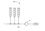
- the waste liquid processing device 101 shown in FIG. 1 directly collects the waste liquid of each waste liquid pipe 1, 2, 3, ... by the waste liquid pump 11 and discharges it to the outside of the machine.
- the scheme is simple in structure, and can realize multi-channel waste liquid discharged by a single pump, but has the following disadvantages: 1. Due to limited flow of the waste liquid pump 11, the waste liquid pipelines 1, 2, 3, ... cannot be discharged in parallel; There will be a situation in which a certain waste liquid pipe is drained in advance and the other waste liquid pipes are discharged poorly, so that only one channel can be drained, and the efficiency is low. 2. The waste liquid needs to flow through the waste liquid pump 11, and the debris present in the waste liquid easily causes the one-way valve in the waste liquid pump 11 to fail, thereby damaging the waste liquid pump 11.
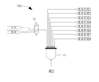
- the waste liquid processing device 102 shown in FIG. 2 uses a waste liquid buffer device with a pressure switch, such as a waste liquid pool 13, to collect and discharge the waste liquid in the machine.
- the waste liquid pool 13 is connected to the pressure supply device (not shown, generally a large flow air pump) through the control valve 12.
- the waste liquid pool 13 collects each waste liquid pipe 1 ⁇ The waste liquid of 8; when the waste liquid pool 13 is switched to the positive pressure state, the waste liquid pool 13 discharges the waste liquid to the outside of the machine.
- the application provides a waste liquid processing device, a method and a sample analyzer, which can timely process the waste liquid generated during the detection process, thereby effectively shortening the waste liquid treatment cycle.
- the first aspect of the present application provides a waste liquid processing apparatus for treating waste liquid in a plurality of waste liquid pipes.
- the waste liquid processing device includes:
- At least two waste liquid pools each of which is in communication with at least one of the waste liquid pipes, the waste liquid pool being used for collecting waste liquid in the connected waste liquid pipe when the inside thereof is under a negative pressure state ;
- a pressure supply device respectively connected to the at least two waste liquid pools for supplying air pressure to each waste liquid pool
- the control device is configured to control the air pressure provided by the pressure supply device for each waste liquid pool according to a preset air pressure timing corresponding to each waste liquid pool, and at least one internal environment of the waste liquid pool at any time during the waste liquid treatment process Under negative pressure to collect waste liquid.
- a second aspect of the present application provides a waste liquid processing apparatus for treating waste liquid in at least two groups of waste liquid pipes.
- the waste liquid processing device includes:
- each waste liquid pool being in communication with a set of the waste liquid pipes, the waste liquid pools being used for collecting waste liquid in the connected waste liquid pipes when the inside thereof is under a negative pressure state, and Discharge the collected waste liquid when it is in a positive pressure state inside;
- a pressure supply device respectively connected to the at least two waste liquid pools for supplying air pressure to each waste liquid pool
- control device configured to control the pressure supply device to alternately provide negative pressure and positive pressure for each waste liquid pool according to a preset air pressure timing corresponding to each waste liquid pool, so that the internals of each waste liquid pool are alternately in a negative pressure state and The positive pressure state alternately collects and discharges the waste liquid, and the waste liquid processing apparatus can simultaneously collect and discharge the waste liquid in the waste liquid processing.
- a third aspect of the present application provides a sample analyzer comprising a waste liquid source and the waste liquid processing device of any of the above embodiments, wherein the waste liquid pool of the waste liquid processing device passes through a plurality of waste liquid pipes and The discharge port of the waste liquid source is connected, and the waste liquid pool is used to treat the waste liquid generated by the waste liquid source connected thereto.
- a fourth aspect of the present application provides a waste liquid processing method, the waste liquid processing method comprising:
- the pressure provided by the pressure supply device for each waste liquid pool is controlled, and at least one of the waste liquid pools is under a negative pressure state at any time during the waste liquid treatment process to collect waste. liquid.
- a fifth aspect of the present application provides a waste liquid processing method, the waste liquid processing method comprising:
- the preset air pressure timing includes a negative pressure period and a positive pressure period, and the corresponding negative pressure period of each waste liquid pool is connected thereto Corresponding to the waste discharge timing of the waste liquid source corresponding to the waste liquid pipeline;
- the pressure supply device is controlled to alternately provide negative pressure and positive pressure for each waste liquid pool, so that the internals of each waste liquid pool are alternately in a negative pressure state and a positive pressure state to be alternately collected.
- the waste liquid processing device capable of simultaneously collecting and discharging the waste liquid in the waste liquid processing.
- the waste liquid processing apparatus and method of the present application can timely collect the waste gas by using at least two waste liquid pools and appropriately setting the preset gas pressure timing to at least two waste liquid pools, so that the waste liquid can be collected in a timely manner. Disposing the waste liquid generated during the detection process, and ensuring that at least one waste liquid pool collects waste liquid at any time during the waste liquid treatment process, which can effectively shorten the waste liquid treatment cycle, and use the waste liquid treatment device And the method of the sample analyzer provides support for increasing the speed of detection.
- FIG. 1 is a schematic structural view of a waste liquid processing apparatus in the prior art.
- FIG. 2 is a schematic structural view of another waste liquid processing apparatus in the prior art.
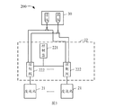
- FIG. 3 is a schematic block diagram of a waste liquid processing apparatus according to an embodiment of the present application.
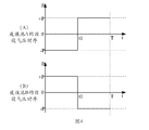
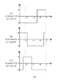
- FIG. 4 is a schematic diagram of a preset air pressure timing corresponding to two waste liquid pools of the waste liquid processing apparatus of FIG. 3.
- FIG. 5 is a schematic diagram of a preset air pressure timing corresponding to three waste liquid pools of the waste liquid processing apparatus of FIG. 3.
- FIG. 5 is a schematic diagram of a preset air pressure timing corresponding to three waste liquid pools of the waste liquid processing apparatus of FIG. 3.
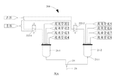
- Fig. 6 is a schematic structural view of a waste liquid processing apparatus according to a first embodiment of the present application.
- FIG. 7 is a schematic structural view of a waste liquid processing apparatus according to a second embodiment of the present application.
- FIG. 8 is a schematic diagram showing the internal structure of a waste liquid pool according to an embodiment of the present application.
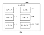
- FIG. 9 is a schematic block diagram of a sample analyzer according to an embodiment of the present application.
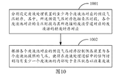
- FIG. 10 is a schematic flow chart of a waste liquid processing method according to a first embodiment of the present application.
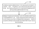
- FIG. 11 is a schematic flow chart of a waste liquid processing method according to a second embodiment of the present application.
- FIG. 3 is a schematic block diagram of a waste liquid processing apparatus 200 according to an embodiment of the present application.
- the waste liquid processing apparatus 200 is for processing waste liquid in a plurality of waste liquid pipes (not shown). It should be noted that the "handling" waste liquid referred to in the present application includes collecting and discharging waste liquid.
- the waste liquid processing apparatus 200 includes at least two waste liquid tanks 21, a control device 22, and a pressure supply device 30. Wherein each of the waste liquid pools 21 is in communication with at least one of the waste liquid pipes.
- the plurality of waste liquid pipes may be pre-divided into at least two sets of waste liquid pipes, each of which is in communication with a set of the waste liquid pipes. Wherein each group of the waste liquid pipeline comprises one or more waste liquid pipelines.
- the pressure supply devices 30 are respectively connected to the at least two waste liquid pools 21 for supplying air pressure to the respective waste liquid pools 21.
- the waste liquid pool 21 is for collecting waste liquid in the connected waste liquid pipe when the inside thereof is in a negative pressure state, and discharging the collected waste liquid when the inside thereof is in a positive pressure state.
- the normal state inside the waste liquid pool 21 is a negative pressure state for collecting and storing waste liquid.
- the control device 22 is configured to control the air pressure provided by the pressure supply device 30 for each waste liquid pool 21 according to a preset air pressure timing corresponding to each waste liquid pool 21, so that at least one time in the waste liquid processing process
- the inside of the waste liquid tank 21 is in a negative pressure state to collect waste liquid.
- the collection process of waste liquid is relatively slow, and the process of discharging waste liquid is relatively fast. Therefore, it is possible to greatly increase the processing speed of the waste liquid by ensuring that the waste liquid can be collected all the time during the waste liquid treatment.
- ensuring that at least one waste liquid pool 21 collects waste liquid at any time during the waste liquid treatment process can also ensure that the waste liquid collection and discharge process can be performed in parallel during the waste liquid treatment process, eliminating the need for serial execution collection and Waiting time during the discharge process.
- the preset air pressure timing can be written into the control program in advance, or can be a manually set air pressure timing.
- control device 22 can also be used to control the pressure supply device 30 to alternately provide negative pressure and positive pressure for each waste liquid pool 21, so that the interior of each waste liquid pool 21 is alternately in a negative pressure state and positive
- the pressure state alternately collects and discharges the waste liquid, and enables the waste liquid processing apparatus 200 to simultaneously collect and discharge the waste liquid during the waste liquid processing.
- the control device 22 can control the air pressure provided by the pressure supply device 30 for each waste liquid pool 21 such that at least one of the waste liquid pools 21 is in a negative pressure state at any time during the waste liquid treatment process.
- the waste liquid is collected, and the inside of at least one waste liquid tank 21 is in a positive pressure state to discharge the waste liquid, so that the waste liquid can be simultaneously collected and discharged at any time.
- control device 22 may control the air pressure supplied by the pressure supply device 30 for each waste liquid pool 21 such that at least one of the waste liquid pools 21 is at a positive pressure at any time during the waste liquid treatment process.
- the state is to discharge the waste liquid, so that the waste liquid processing device can collect and discharge the waste liquid at a certain time to improve the waste liquid treatment efficiency.
- the preset air pressure timing includes a negative pressure period and a positive pressure period.
- the control device 22 is configured to control the pressure supply device 30 to provide a negative pressure for each waste liquid pool 21 during a negative pressure period corresponding to each waste liquid pool 21, and during a positive pressure period corresponding to each waste liquid pool 21
- the pressure supply device 30 is controlled to supply a positive pressure to each of the waste liquid pools 21, respectively.
- the corresponding negative pressure periods of the at least two waste liquid pools 21 may not cross each other, so that only one waste liquid pool collects the waste liquid at any time during the waste liquid treatment process.
- the negative pressure periods corresponding to the two waste liquid pools A and B do not cross each other, so that there is only one waste liquid at any time during the waste liquid treatment process.
- Pool A or B is collecting waste liquid.
- the positive pressure periods corresponding to the two waste liquid pools A, B may not cross each other, so that there is only one waste liquid pool A or B at any time during the waste liquid processing.
- the waste liquid is discharged, and the action of collecting the waste liquid and discharging the waste liquid can be simultaneously performed in the waste liquid treatment process.
- the corresponding negative pressure periods of the at least two waste liquid pools 21 may partially intersect such that one or more waste liquid pools are present at any time during the waste liquid processing. 21 is collecting waste liquid.
- the negative pressure periods corresponding to the three waste liquid pools A, B, and C partially intersect, and at least any time during the waste liquid treatment process.
- a waste liquid pool 21 is collecting waste liquid.
- the waste liquid pools A, B, and C are collecting waste liquid at the same time, and the waste liquid is collected at time t4.
- Pools B and C are collecting waste liquid at the same time. It can be understood that, in other embodiments, the positive pressure periods corresponding to the three waste liquid pools A, B, and C may be partially crossed, so that at least one waste liquid pool is discharged at any time during the waste liquid treatment process.
- At least one waste liquid pool 21 is collecting and/or discharging waste liquid at any time during the waste liquid treatment process, so that the waste liquid processing apparatus 200 can perform the collection waste liquid and discharge in parallel in the waste liquid processing process. The action of the waste liquid.
- the pressure supply device 30 includes a source of negative pressure and a source of positive pressure, wherein the source of negative pressure is used to provide a negative pressure, and the source of positive pressure is used to provide a negative Pressure.
- the pressure supply device 30 can be adjusted to generate a negative pressure and a positive pressure.
- the pressure supply device 30 can supply a negative pressure to the waste liquid pool 21 through a pneumatic pipe, for example, the pressure supply device 30 draws air through a pneumatic pipe to make the waste liquid pool 21 The negative pressure is generated, and the waste liquid generated by the waste liquid source can be sucked from the discharge port of the waste liquid source into the waste liquid pipe under the negative pressure suction, and then sucked into the waste liquid pool 21 from the waste liquid pipe.
- the control device 22 includes a controller 221 and at least two control valves 222.
- Each control valve 222 is connected between the pressure supply device 30 and a waste liquid pool 21, and the controller 221
- the control valve 222 is configured to control the air pressure provided by the pressure supply device 30 for each waste liquid pool 21 by controlling the conduction state of each control valve 222, thereby controlling each waste liquid pool 21 Internal pressure status.
- the controller 221 can be a single chip microcomputer, a programmable logic controller (PLC) or other controller.
- each of the control valves 222 includes at least a negative pressure channel and a positive pressure channel, and the controller 221 is configured to alternately conduct the negative pressure channel and the positive pressure channel of each of the control valves 222 to control the pressure supply.
- the device 30 alternately supplies a negative pressure and a positive pressure to each of the waste liquid pools 21.
- FIG. 6 is a schematic structural diagram of a waste liquid processing apparatus 200 according to a first embodiment of the present application.
- the waste liquid processing apparatus 200 includes two waste liquid pools 21-1 and 21-2, two control valves 222-1 and 222-2, and eight waste liquid pipes 1 to 8, The negative pressure periods corresponding to the two waste liquid pools 21-1 and 21-2 do not cross each other as an example.
- the waste liquid pools 21-1 are respectively connected to the waste liquid pipes 1 to 4, and the waste liquid pools 21-2 are respectively connected to the waste liquid pipes 5 to 8, and the waste liquid pools 21-1 and 21-2 are A drain port 2111 is provided at the bottom.
- the waste liquid pool 21-1 and the negative pressure port of the pressure supply device 30 It is connected and disconnected from the positive pressure port, and the waste liquid pool 21-1 is in a negative pressure state, which enables the waste liquid pool 21-1 to collect the waste liquid in the waste liquid pipes 1 to 4.
- the positive pressure passage of the control valve 222-2 is turned on, and the waste liquid pool 21-2 is disconnected from the negative pressure port of the pressure supply device 30 and communicates with the positive pressure port, the waste The inside of the liquid pool 21-2 is in a positive pressure state, and the waste liquid in the waste liquid pool 21-2 is discharged to the outside of the machine through the liquid discharge port 2111 of the waste liquid tank 21-2.
- the waste liquid tank 21-1 is disconnected from the negative pressure port of the pressure supply device 30 and is connected to the positive pressure port.
- the waste liquid pool 21-1 is switched to a positive pressure state, and the waste liquid in the waste liquid tank 21-1 is discharged to the outside of the machine through the liquid discharge port 2111 of the waste liquid tank 21-1.
- the conduction position of the control valve 222-2 is switched to the negative pressure passage, and the waste liquid tank 21-2 is in communication with the negative pressure port of the pressure supply device 30 and is disconnected from the positive pressure port.
- the waste liquid tank 21-2 is in a negative pressure state, and the pressure enables the waste liquid pool 21-2 to collect the waste liquid in the waste liquid pipes 5 to 8.
- the number of the waste liquid pools 21 is not limited to two, the number of the control valves 222 is not limited to two, and the number of the waste liquid pipes is not limited to eight.
- the waste liquid processing apparatus 200 of the present application can rapidly collect and discharge waste liquid by controlling the pressure supply apparatus 30 to alternately supply negative pressure and positive pressure to the respective waste liquid pools 21.
- the pressure supply device 30 can also supply only the negative pressure to the waste liquid pool 21 to control the collection of the waste liquid pool 21 without considering the speed of discharging the waste liquid. Waste liquid. When the negative pressure in the waste liquid tank 21 is released, the waste liquid in the waste liquid tank 21 can be discharged from the liquid discharge port 2111 of the waste liquid pool 21 by its own gravity.
- the waste liquid processing apparatus 200 of the present application controls the waste liquid pool 21 to be alternately negative at a preset timing by using at least two waste liquid pools 21 and appropriately setting preset gas pressure timings to at least two waste liquid pools.
- the pressure state and the positive pressure state enable each waste liquid pool to collect and discharge the waste liquid in the plurality of waste liquid pipes in parallel, and at the same time ensure that at least one waste liquid pool collects the waste liquid at any time during the waste liquid treatment process. Therefore, it is possible to effectively shorten the waste liquid processing cycle, and provide support for the detection device (for example, the sample analyzer) using the waste liquid processing apparatus 200 to increase the detection speed.
- the waste liquid processing apparatus 200 of the present application has a simple structure and a low production cost, and is advantageous for the waste liquid processing apparatus 200 to be widely applied to various detecting apparatuses.
- one end of the plurality of waste liquid pipes is respectively connected to the discharge ports of the plurality of waste liquid sources, and the other end is connected to the corresponding waste liquid pool 21 according to the waste discharge timing of the connected waste liquid sources.
- the negative pressure period corresponding to each waste liquid pool 21 corresponds to the waste discharge timing of the waste liquid source corresponding to the waste liquid pipeline connected thereto.
- the set time may be set according to the waste discharge time of each waste liquid source.
- the waste liquid conduits connected with the respective waste liquid sources are reasonably distributed into the corresponding waste liquid pools, so that the negative pressure period of the waste liquid pool Corresponding to the discharge time of the corresponding waste liquid source, so that the waste liquid pool can be controlled as much as possible during the waste liquid source discharge, and the collected waste can be discharged during the suspension or stop of the waste liquid source. liquid.
- each waste liquid line is connected to a corresponding waste liquid tank 21 in accordance with the exhaust timing of the waste liquid source to which it is connected.
- the other ends of the respective waste liquid pipes 1 to 4 are respectively connected to the waste liquid pool 21-1, and the other ends of the respective waste liquid pipes 5 to 8 are respectively associated with the waste liquid pool 21-2. connection.
- the other end of the plurality of waste liquid pipes in the plurality of waste liquid pipes is connected to one or more waste liquid pools 21 according to the waste discharge timing of the connected waste liquid source, and the one or more The sum of the negative pressure periods corresponding to the waste liquid pool 21 corresponds to the waste discharge timing of the waste liquid source corresponding to the same waste liquid pipeline connected thereto.
- the connecting member 25 for example, a three-way head
- the sum of the negative pressure periods corresponding to the waste liquid pools 21-1 and 21-2 corresponds to the waste discharge timing of the waste liquid source corresponding to the waste liquid pipeline 5.
- the waste liquid processing device 200 (201) of the present application can dispose the waste liquid generated in the detection process in time by setting at least two waste liquid pools 21 and matching the preset air pressure timing, which is beneficial to the improvement of the detection device. Detection speed.
- the other end of the plurality of waste liquid pipes can communicate with the corresponding waste liquid pool 21 according to the chemical properties of the waste liquid discharged from the waste liquid source connected thereto, so that the chemical reaction and the waste generated can be generated.
- the liquid is discharged separately to different waste liquid tanks 21.
- the plurality of waste liquid pipes may be pre-divided into at least two sets of waste liquid pipes, and the waste liquid discharged from the waste liquid source connected to each set of waste liquid pipes is mixed without mutual chemical reaction. Dirt is generated, and each of the waste liquid pools 21 is in communication with a set of the waste liquid pipes.
- waste liquids of different chemical properties can be collected and collected to avoid accidents and accidents that may occur after the mixing of waste liquids of different chemical properties, and also to reduce the pollution of the waste liquid pool 21 by the dirt generated after the waste liquid is mixed. In order to reduce the maintenance difficulty and maintenance cost of the waste liquid pool 21.
- the waste liquid processing apparatus 200 (201) further includes a liquid level sensor 215 (shown in FIG. 8) disposed inside each waste liquid pool 21, and the controller 221 is also related to the liquid level.
- the sensor 215 is connected.
- the liquid level sensor 215 is used to sense the liquid level height inside the waste liquid pool 21 in which it is located.
- the liquid level sensor 215 employs a float sensor.
- the float sensor detects the liquid level by the position of the float, and when the liquid level rises to the position of the float, the float is lifted by the liquid because the specific gravity of the float is smaller than the detection liquid. When the liquid level drops below the position of the float, the float is suspended in the waste pool. It can be understood that the float sensor can generate different trigger signals corresponding to different states of the float to report different liquid level heights.
- the level sensor can employ an electrode sensor.
- the electrode sensor detects the liquid level by determining whether the two electrodes are turned on, and when the liquid level rises to the position of the electrode so that both electrodes are in contact with the liquid, the electrodes are electrically connected. When the liquid level drops below the position of the electrode, the electrode is disconnected. It can be understood that the electrode sensor can generate different trigger signals corresponding to the on and off states of the electrodes to report different liquid level heights.
- the controller 221 is also used to During the negative pressure period corresponding to each waste liquid pool 21, the liquid pressure data sensed by the liquid level sensor 215 inside each waste liquid pool 21 is used to control the duration of the negative pressure provided by the pressure supply device 30 for each waste liquid pool 21. Thereby, the amount of waste liquid in each waste liquid pool 21 is controlled.
- the controller 221 is configured to be negative in the corresponding waste liquid pool 21 when the liquid level sensor 215 senses that the liquid level in the corresponding waste liquid pool 21 is higher than the first preset height.
- the pressure supply device 30 is controlled to suspend the supply of the negative pressure to the corresponding waste liquid pool 21, so that the corresponding waste liquid pool 21 is suspended to collect the waste liquid, wherein the first preset height can be set to prevent the waste liquid from entering.
- the safe height of the vent 2122 In other embodiments, the first predetermined height may also be set to prevent the waste liquid from overflowing the safe height of the waste liquid pool 21.
- the controller 221 may also control the pressure supply device 30 during the negative pressure period corresponding to the corresponding waste liquid pool 21 when the liquid level height is higher than the first preset height.
- the waste liquid pool 21 provides a positive pressure to cause the corresponding waste liquid tank 21 to discharge the waste liquid.
- the controller 221 can be connected to the pressure supply device 30, and the controller 221 can control the pressure supply device 30 to be suspended into a corresponding waste liquid pool by closing the negative pressure port of the pressure supply device 30. 21 provides negative pressure.
- the controller 221 can also control the pressure supply device 30 to suspend providing a negative pressure to the corresponding waste liquid pool 21 by disconnecting the negative pressure passage of the corresponding control valve 222, for example, the control valve 222 A closed passage may also be included, and the controller 221 may disconnect the pressure supply device 30 from the corresponding waste liquid pool 21 by switching the negative pressure passage of the corresponding control valve 222 to the closed passage.
- the connection is controlled to control the supply of the pressure device 30 to provide a negative pressure to the corresponding waste liquid pool 21.
- the waste liquid pool 21 may not perform positive pressure discharge per cycle, or may shorten the time of positive pressure discharge according to actual conditions, by designing the waste liquid pool 21 enough.
- the positive pressure liquid discharge is performed.
- the controller 221 is further configured to control the liquid level data sensed by the liquid level sensor 215 inside each waste liquid pool 21 during a positive pressure period corresponding to each waste liquid pool 21
- the pressure supply device 30 supplies the respective waste liquid pools 21 with a positive pressure for controlling the amount of waste liquid in each of the waste liquid pools 21.
- the controller 221 is configured to: when the liquid level sensor 215 senses that the liquid level in the corresponding waste liquid pool 21 is lower than the second preset height, the corresponding waste liquid pool 21 corresponds to the positive During the pressure period, the pressure supply device 30 is controlled to suspend the supply of the positive waste liquid pool 21 with a positive pressure, so that the corresponding waste liquid pool 21 is suspended.
- the second preset height may be set to be higher than the safe height of the liquid discharge port 2111 to ensure that a certain amount of waste liquid is stored in the waste liquid pool 21, and the row of the waste liquid pool 21 is prevented.
- the liquid port 2111 is open to the atmosphere to cause unnecessary system air consumption. It can be understood that the position of the liquid discharge port 2111 can be set at the lowest point of the bottom of the waste liquid pool 21.
- the controller 221 may also control the pressure supply device 30 during the positive pressure period corresponding to the corresponding waste liquid pool 21 when the liquid level height is lower than the second preset height.
- the waste liquid tank 21 provides a negative pressure to continue collecting waste liquid.
- the controller 221 can be connected to the pressure supply device 30, and the controller 221 can control the pressure supply device 30 to be suspended into a corresponding waste liquid pool by closing the positive pressure port of the pressure supply device 30. 21 provides positive pressure.
- the controller 221 can also control the pressure supply device 30 to temporarily provide a positive pressure to the corresponding waste liquid pool 21 by disconnecting the positive pressure passage of the corresponding control valve 222.
- the control valve 222 A closed passage may also be included, and the controller 221 may disconnect the pressure supply device 30 from the corresponding waste liquid pool 21 by switching the positive positive pressure passage of the corresponding control valve 222 to the closed passage.
- the connection is controlled to control the supply of the pressure device 30 to provide a positive pressure to the respective waste liquid pool 21.
- the waste liquid processing apparatus 200 (201) may further include a control switch connected to the liquid discharge port 2111 of the waste liquid pool 21, and the controller 221 is used in the waste liquid pool 21 The control switch is opened when the inside is in a negative pressure state to prevent the liquid discharge port 2111 of the waste liquid pool 21 from passing through the atmosphere during the collection of the waste liquid to affect the collection of the waste liquid.
- the waste liquid processing apparatus 200 (201) further includes a waste pipe 23 connected to the liquid discharge port 2111 of the waste liquid pool 21, and the waste pipe 23 is used for waste connected thereto.
- the waste liquid in the liquid pool 21 is disposed outside the machine.
- the waste liquid processing apparatus 200 (201) includes a waste pipe 23, such as shown in Figures 6 and 7, the waste pipe 23 is connected to each other through a joint 24 (e.g., a three-way head)
- the liquid discharge port 2111 of the waste liquid pool 21 is connected, and the waste storage pipe 23 is for discharging the waste liquid in each waste liquid pool.
- the waste liquid processing apparatus 200 (201) includes a plurality of waste pipes 23, each of which is connected to a liquid discharge port 2111 of at least one waste liquid tank 21,
- the waste pipe 23 is for discharging the waste liquid in the waste liquid tank connected thereto.
- the present application also provides a waste liquid pool for treating waste liquid.
- FIG. 8 is a schematic diagram of the internal structure of a waste liquid pool 21 according to an embodiment of the present application.
- the waste liquid pool 21 includes a body 211 and a receiving cavity 217 disposed inside the body 211, and the receiving cavity 217 is configured to store waste liquid.
- the waste liquid pool 21 further includes a plurality of liquid inlets 2121, a vent 2122, and a liquid discharge port 2111, wherein the plurality of liquid inlets 2121 and the vents 2122 are disposed in the The upper portion of the receiving cavity 217 is disposed at a lower portion of the receiving cavity 217.
- Each of the liquid inlets 2121 is connected to a waste liquid pipe, and the waste liquid can flow into the waste liquid pool 21 through the waste liquid pipe and the corresponding liquid inlet port 2121, and the liquid discharge port 2111 is used for discharging the waste liquid pool. Waste liquid in 21.
- the number of the vents 2122 may be one, and the positive pressure port and the negative pressure port of the pressure supply device may be connected to the vent port 2122 through the same control valve, and the conduction position of the control valve may be controlled. Switching control of positive pressure and negative pressure in the waste liquid pool.
- the number of the vents 2122 may also be two.
- the positive pressure port and the negative pressure port of the pressure supply device are respectively connected to the two vent ports 2122 through a control valve, respectively, by controlling the conduction of the two control valves respectively. The state can realize the switching control of the positive pressure and the negative pressure in the waste liquid pool.
- the body 211 is a cavity that is open at one end and closed at the other end, and the waste liquid pool 21 further includes a cover 212 for closing the body.
- the opening of 211 The shape and size of the body 211 and the cover 212 can be specifically designed according to requirements, and are not specifically limited herein.
- the plurality of liquid inlets 2121 and the vents 2122 are disposed on the cover 212, and the liquid discharge port 2111 is disposed on the bottom wall of the body 211.
- the plurality of liquid inlets 2121 and the vents 2122 may be disposed on an upper portion of the sidewall of the body 211, or an upper portion of the sidewall of the body 211 and the cover 212.
- the plurality of liquid inlets 2121 and the vents 2122 are provided.
- the liquid discharge port 2111 may be disposed on a sidewall of the body 211, or the bottom wall of the body 211 and the sidewall of the body 211 may be provided with the liquid discharge port 2111.
- the body 211 is a closed cavity. It can be understood that in the other embodiment, the cover 212 can be omitted.
- the top wall of the body 211 and/or the upper portion of the side wall of the body 211 are provided with the plurality of liquid inlets 2121 and the venting ports 2122.
- the position of the vent 2122 should be set as high as possible, as the vent 2122 should be as close as possible to the top of the body 211.
- the waste liquid pool 21 further includes a first baffle 2141 received in the receiving cavity 217, and the first baffle 2141 is located in the vent 2122 and the liquid discharge port 2111. And disposed adjacent to the vent 2122. It can be understood that "close” as used herein means that the first baffle 2141 is close to the vent 2122 with respect to the position of the liquid discharge port 2111, rather than referring to the vent 2122.
- the waste liquid pool 21 further includes a plurality of draft tubes 213 received in the receiving cavity 217, and the nozzles at one end of the plurality of draft tubes 213 and the plurality of liquid inlets respectively Portion or all of the liquid inlets 2121 of the port 2121 are connected to introduce the waste liquid in the waste liquid pipe into the draft pipe, and the nozzle of the other end of the plurality of draft pipes 213 is disposed under the first baffle 2141.
- the plurality of draft tubes 213 are configured to guide the waste liquid to below the first baffle 2141 in the receiving cavity 217, the first baffle 2141 is configured to block the foam in the receiving cavity 217 and / or waste liquid enters the vent 2122.
- a part of the liquid inlet 2121 can be used for connecting a liquid pipe containing no waste liquid, such as a liquid pipe connecting the hemolytic agent, in order to facilitate the hemolytic agent entering the inside of the waste liquid pool 21 to clean the waste liquid pool 21
- the accommodating chamber 217 is configured such that the hemolytic agent flows into the accommodating chamber 217 from the highest possible portion of the effluent pool 21, and in one embodiment, the liquid inlet 2121 of the liquid conduit connecting the hemolytic agent can be
- the air inlet is not disposed in the receiving cavity 217 and is connected to the air guiding tube 213. In this case, the nozzles at one end of the plurality of draft tubes 213 are respectively connected to a part of the liquid inlets 2121 of the plurality of inlet ports 2121.
- the liquid inlet 2121 of the liquid pipe connecting the hemolytic agent may be disposed on the first baffle 2141, for example, on the cover 212 or the top wall of the body 211.
- the inlet chamber 217 is connected to the inlet port 2121 by a draft tube 213, and the nozzle of the draft tube 213 is disposed below the first flap 2141.
- the nozzles at one end of the plurality of draft tubes 213 are respectively connected to all the liquid inlets 2121 of the plurality of inlet ports 2121.
- the waste liquid impacts the liquid surface at a high speed from the upper portion to the bottom portion of the receiving chamber 217, so that the waste liquid is liable to splash. Further, a part of a reagent containing a large amount of a surfactant, such as a hemolytic agent, tends to generate a large amount of foam in the housing chamber 217, and the foam accumulates above the liquid surface.
- a surfactant such as a hemolytic agent
- the waste liquid pool 21 of the present application is configured to provide a first baffle 2141 adjacent to the vent 2122 in the accommodating cavity 217, and to guide the liquid flowing out from the liquid inlet 2121 to the first block by using the draft tube 213.
- the waste liquid pool 21 further includes a second baffle 2142.
- the second baffle 2142 is received in the receiving cavity 217 and located in the first baffle 2141 and the liquid discharge port. Between 2111, that is, the first baffle 2141 is located above the second baffle 2142.
- the number of the plurality of draft tubes 213 is plural, and the nozzles at the other end of the plurality of the draft tubes 213 are disposed on the second baffle according to the property of the waste liquid that is diverted Above and/or below 2142, different waste liquids are introduced into different heights inside the receiving chamber 217, respectively.
- a nozzle at the other end of the draft tube that conducts the blood-free waste liquid may be disposed on the second baffle 2142 to drain the waste liquid onto the second baffle 2142;
- the nozzle at the other end of the draft tube of the high-concentration blood waste liquid is disposed under the second baffle 2141 to drain the waste liquid below the second baffle 2142.
- each of the draft tubes can have different lengths at this time, so as to drain the waste liquids of different waste liquid pipes to different height portions of the waste liquid pool.
- the waste liquid pool 21 further includes a third baffle, and the third baffle is received in the receiving cavity 217 and located in the first baffle 2141 and the second baffle 2142. Between the third baffles may include one or more baffles. By providing the first, second, and third baffles, different liquids introduced into the receiving chamber 217 can be blocked under different baffles according to actual use.
- a nozzle at the other end of the draft tube of the flow guiding hemolytic agent may be disposed between the first baffle 2141 and the third baffle to facilitate drainage of the hemolytic agent from the receiving chamber 217 as high as possible. Washing the receiving cavity 217 into the receiving cavity 217, while avoiding the foam generated by the hemolytic agent from entering the vent 2122; and guiding the other end of the guiding tube of the waste liquid containing low concentration of blood
- the nozzle is disposed between the third baffle and the second baffle 2142 to drain the waste liquid onto the second baffle 2142; the tube at the other end of the diversion tube that will guide the waste liquid containing the high concentration of blood
- the port is disposed below the second baffle 2141 to drain the waste liquid below the second baffle 2142.
- the nozzles at the other ends of the plurality of draft tubes 213 may also be disposed below the second baffle 2142.
- the position of the nozzle at the other end of the draft tube 213 can be set as low as possible, such as as close as possible to the liquid discharge port 2111 at the bottom of the waste liquid tank 21, so that the waste liquid can be introduced into the waste liquid pool.
- the other ends of the plurality of draft tubes 213 are sequentially passed through the one or more baffles of the waste liquid pool 21 from top to bottom, respectively, so that the nozzle at the other end is located at the same Under the baffles that pass through, the various baffles of the waste liquid pool 21 are also used to hold the draft tube 213 disposed therethrough to prevent the draft tube 213 from being in the waste collection process.
- the contents of the containment chamber 217 are disturbed to affect the collection of waste liquid or other safety accidents.
- the other end of the plurality of draft tubes 213 may extend along the inner wall of the receiving cavity 217 toward the bottom of the receiving cavity 217, and the other end of the nozzle is located at the first end. Above and/or below the baffle 2142.
- the waste liquid impacts the liquid surface at a high speed from the upper portion to the bottom portion of the receiving chamber 217, so that the waste liquid is easily splashed, and the entire waste liquid pool is made. 21
- the inner wall will be exposed to the waste liquid. After long-term use, the inner wall of the whole waste liquid pool 21 will have dirt (such as blood stains) attached. Therefore, when the waste liquid pool is maintained, the entire waste liquid pool needs to be filled with the cleaning liquid, which is difficult to maintain. It is difficult to achieve self-maintenance of the machine, and often requires manual manual maintenance to increase maintenance costs.
- the baffles of the waste liquid pool 21 are also used to prevent the waste liquid flowing out of the nozzle of the draft tube 213 located below it from coming into contact with the inner wall of the receiving chamber 217 located above it.
- the first baffle 2141 can block the droplets of the hemolytic agent and the first baffle 2141 as much as possible.
- the inner wall of the upper body 211 is in contact, so that the possibility of foam or liquid droplets generated by the hemolytic agent entering the vent 2122 can be reduced.
- the third baffle can block the blood containing low concentration
- the waste liquid droplets are in contact with the inner wall of the body 211 above the third baffle to reduce contamination of the inner wall of the body 211 by the waste liquid.
- the second baffle 2141 can prevent the liquid droplets containing the high concentration of blood from falling.
- the inner wall of the body 211 above the second baffle 2142 contacts to reduce the contamination of the inner wall of the body 211 by the waste liquid.
- the waste liquid pool 21 of the present application is provided with a baffle in the accommodating cavity 217 so that the waste liquid does not pass over the baffle and is in contact with the inner wall of the main body 211 located above the baffle, and is only blocked after a long time of use.
- the walls below the board are dirty and require maintenance, which reduces reagent consumption during maintenance of the waste pool and is easier to maintain.
- the waste liquid pool 21 further includes a connecting rod 216, and one end of the connecting rod 216 is fixed on the top wall of the receiving cavity 217 (for example, the cover 212 or the top of the body 211), and One end extends in a direction close to the bottom of the receiving cavity 217, and each layer of the baffle of the waste liquid pool 21 is sleeved on the connecting rod 216.
- the waste liquid pool 21 further includes the liquid level sensor 215 disposed inside the receiving cavity 217, and the liquid level sensor 215 is used to sense the liquid level inside the waste liquid pool 21. height.
- the liquid level sensor 215 is disposed on the connecting rod 216. In other embodiments, the liquid level sensor 215 can be disposed on the inner wall of the body 211 or otherwise disposed in the receiving cavity 217.
- waste liquid tank 21 and waste liquid processing apparatus 200 (201) of the present application can be applied to various detecting apparatuses that need to discharge liquid, such as an immunoassay analyzer, a blood cell analyzer, a biochemical analyzer, a blood coagulation analyzer, and urine. Analyzers, etc.
- the present application further provides a sample analyzer based on the waste liquid pool 21 and the waste liquid processing device 200 (201).
- FIG. 9 is a schematic block diagram of a sample analyzer 400 according to an embodiment of the present application.
- the sample analyzer 400 may be an immune analyzer, a blood cell analyzer, a biochemical analyzer, a blood coagulation analyzer, a urine analyzer, or the like.
- the sample analyzer 400 includes at least a sample introduction system 41, a reagent tray 42, a sample application system 43, a cleaning system 44, a reaction system 45, and the above-described waste liquid processing apparatus 200 (201).
- the sample introduction system 41 provides the sample analyzer 400 with a sample to be detected
- the reagent disk 42 provides the sample analyzer 400 with reagents for detection
- the sample application system 43 is used for collecting samples and The reagents are injected into the reaction cell of the reaction system 45.
- the loading system 43 can include a moving mechanism for collecting samples and reagents, and a loading needle that is cleaned by the cleaning system 44 each time the sample or reagent is collected.
- the cleaning system washes the sample needle with a cleaning liquid in the cleaning pool, and the cleaned waste liquid is discharged through the waste liquid processing device 200 (201). Since the sample introduction system 41, the reagent tray 42, the sample application system 43, the cleaning system 44, the reaction system 45, and the like are not the focus of the improvement of the present application, they are not described herein.
- the waste liquid pool 21 of the waste liquid processing apparatus 200 (201) is connected to the discharge port of the waste liquid source of the sample analyzer 400 through a plurality of waste liquid pipes, and the waste liquid pool 21 is used.
- the waste liquid source of the sample analyzer 400 may be at least one of a sample needle cleaning tank, a reagent tray discharge waste pipeline, a magnetic separation disk, and a reaction cell. It will be appreciated that the source of waste liquid may also be other components of the sample analyzer 400 that require drainage.
- the present application further provides a waste liquid processing method based on the above-mentioned waste liquid pool 21 and waste liquid processing apparatus 200 (201).
- FIG. 10 is a schematic flowchart of a waste liquid processing method according to a first embodiment of the present application.
- the waste liquid processing method of the embodiment of the present application is not limited to the steps and the sequence in the flowchart shown in FIG. The steps in the illustrated flow diagrams can be added, removed, or changed in order, depending on the requirements.
- the waste liquid processing method includes the following steps:
- Step 1001 respectively, setting a preset air pressure timing corresponding to at least two waste liquid pools of the waste liquid processing device, wherein the preset air pressure timing includes a negative pressure period, and a corresponding negative pressure period of each waste liquid pool is connected thereto
- the discharge timing of the waste liquid source corresponding to the waste liquid pipeline corresponds.
- the preset air pressure timing further includes a positive pressure period
- the step of controlling the air pressure provided by the pressure supply device for each waste liquid pool according to the preset air pressure timing corresponding to each waste liquid pool includes:
- the pressure supply device alternately supplies negative pressure and positive pressure to each waste liquid pool, so that the internals of the respective waste liquid pools are alternately in a negative pressure state and a positive pressure state, Alternately collect and discharge waste liquid.
- the steps of controlling the pressure supply device to alternately provide negative pressure and positive pressure for each waste liquid pool according to the preset air pressure timing corresponding to each waste liquid pool include:
- Step 1002 Control the air pressure provided by the pressure supply device for each waste liquid pool according to the preset air pressure timing corresponding to each waste liquid pool, so that at least one of the waste liquid pools is under a negative pressure state at any time during the waste liquid treatment process. To collect waste liquid.
- the waste liquid processing method further includes:
- the liquid pressure data sensed by the liquid level sensor inside each waste liquid pool is used to control the duration of the negative pressure provided by the pressure supply device for each waste liquid pool to control each The amount of waste liquid in the waste pool.
- the step of controlling the duration of the pressure supply device to provide a negative pressure for each waste liquid pool according to the liquid level data sensed by the liquid level sensor inside each waste liquid pool comprises:
- the pressure supply device is controlled to suspend the negative pressure to the corresponding waste liquid pool, and the corresponding waste liquid pool is suspended to collect the waste liquid.
- the waste liquid processing method further includes:
- the liquid pressure data sensed by the liquid level sensor inside each waste liquid pool is used to control the length of time that the pressure supply device provides positive pressure for each waste liquid pool to control each The amount of waste liquid in the waste pool.
- controlling the duration of the positive pressure provided by the pressure supply device according to the liquid level data sensed by the liquid level sensor inside each waste liquid pool includes:
- the pressure supply device is controlled to suspend to provide a positive pressure to the corresponding waste liquid pool, so that the corresponding waste liquid pool is suspended.
- the waste liquid processing method provided by the embodiment provides at least two waste liquid pools to collect waste liquids in a time-sharing manner by using at least two waste liquid pools and appropriately setting preset gas pressure timings to at least two waste liquid pools. At the same time, it is ensured that at least one waste liquid pool collects the waste liquid at any time during the waste liquid treatment process, and the waste liquid generated in the detection process can be timely processed to shorten the waste liquid treatment cycle, and the waste liquid treatment device is used.
- the method's sample analyzer provides support for increasing detection speed.
- the collection process of waste liquid is relatively slow, and the process of discharging waste liquid is relatively fast. Therefore, it is possible to greatly increase the processing speed of the waste liquid by ensuring that the waste liquid can be collected all the time during the waste liquid treatment.
- ensuring that at least one waste liquid pool collects waste liquid at any time during the waste liquid treatment process can also ensure that the waste liquid collection and discharge process can be carried out in parallel during the waste liquid treatment process, eliminating the need for serial execution of collection and discharge. Waiting time in the process.
- FIG. 11 is a schematic flowchart diagram of a waste liquid processing method according to a second embodiment of the present application. It should be noted that the waste liquid processing method of the embodiment of the present application is not limited to the steps and the sequence in the flowchart shown in FIG. The steps in the illustrated flow diagrams can be added, removed, or changed in order, depending on the requirements.
- the waste liquid processing method includes the following steps:
- Step 1101 respectively, setting a preset air pressure timing corresponding to at least two waste liquid pools of the waste liquid processing device, wherein the preset air pressure timing includes a negative pressure period and a positive pressure period, and a corresponding negative pressure period of each waste liquid pool Corresponding to the waste discharge timing of the waste liquid source corresponding to the waste liquid pipe connected thereto.
- the air pressure provided by the pressure supply device for each waste liquid pool according to the preset air pressure timing corresponding to each waste liquid pool includes:
- Step 1102 Control the air pressure provided by the pressure supply device for each waste liquid pool according to the preset air pressure timing corresponding to each waste liquid pool, so that the internals of each waste liquid pool are alternately in a negative pressure state and a positive pressure state to alternately collect and discharge.
- the waste liquid is passed, and the waste liquid processing apparatus can simultaneously collect and discharge the waste liquid in the waste liquid processing.
- the pressure provided by the pressure supply device for each waste liquid pool is at a negative pressure state at any time during the waste liquid treatment process to collect the waste liquid, and at least one waste liquid The inside of the tank is in a positive pressure state to discharge the waste liquid, so that the waste liquid can be collected and discharged simultaneously at any time.
- the pressure provided by the pressure supply device for each waste liquid pool is controlled such that at least one of the waste liquid pools is at a positive pressure state at any time during the waste liquid treatment process to discharge the waste liquid, so that it can be executed in parallel at a certain time.
- the collection and discharge of waste liquids saves the waiting time for serial execution of collection and discharge of waste.
- the ability to collect and discharge waste liquids can be performed in parallel, saving the waiting time for serial execution of collection and discharge of waste.
- the waste liquid processing method further includes:
- the liquid pressure data sensed by the liquid level sensor inside each waste liquid pool is used to control the duration of the negative pressure provided by the pressure supply device for each waste liquid pool to control each The amount of waste liquid in the waste pool.
- controlling the duration of the negative pressure provided by the pressure supply device for each waste liquid pool according to the liquid level data sensed by the liquid level sensor inside each waste liquid pool includes:
- the pressure supply device is controlled to suspend the negative pressure to the corresponding waste liquid pool, and the corresponding waste liquid pool is suspended to collect the waste liquid.
- the waste liquid processing method further includes:
- the liquid pressure data sensed by the liquid level sensor inside each waste liquid pool is used to control the length of time that the pressure supply device provides positive pressure for each waste liquid pool to control each The amount of waste liquid in the waste pool.
- controlling the duration of the positive pressure provided by the pressure supply device according to the liquid level data sensed by the liquid level sensor inside each waste liquid pool includes:
- the pressure supply device is controlled to suspend to provide a positive pressure to the corresponding waste liquid pool, so that the corresponding waste liquid pool is suspended.
- the waste liquid processing method provided by the embodiment can realize the parallel and alternate collection and discharge of each waste liquid pool by using at least two waste liquid pools and reasonably setting preset gas pressure timings to at least two waste liquid pools.
- the waste liquid in the waste liquid pipeline can timely process the waste liquid generated during the detection process to shorten the waste liquid treatment cycle, and provides support for the sample analyzer using the waste liquid treatment device and method to increase the detection speed.
Landscapes
- Engineering & Computer Science (AREA)
- Health & Medical Sciences (AREA)
- Life Sciences & Earth Sciences (AREA)
- Chemical & Material Sciences (AREA)
- Immunology (AREA)
- Mechanical Engineering (AREA)
- General Engineering & Computer Science (AREA)
- Urology & Nephrology (AREA)
- Molecular Biology (AREA)
- Hematology (AREA)
- Biomedical Technology (AREA)
- Cell Biology (AREA)
- Medicinal Chemistry (AREA)
- Water Supply & Treatment (AREA)
- Environmental & Geological Engineering (AREA)
- Biotechnology (AREA)
- Hydrology & Water Resources (AREA)
- General Chemical & Material Sciences (AREA)
- Microbiology (AREA)
- Electrochemistry (AREA)
- Chemical Kinetics & Catalysis (AREA)
- Food Science & Technology (AREA)
- Organic Chemistry (AREA)
- Physics & Mathematics (AREA)
- Analytical Chemistry (AREA)
- Biochemistry (AREA)
- General Health & Medical Sciences (AREA)
- General Physics & Mathematics (AREA)
- Pathology (AREA)
- Automatic Analysis And Handling Materials Therefor (AREA)
- Physical Water Treatments (AREA)
- Cleaning In General (AREA)
Abstract
L'invention concerne un dispositif de traitement de déchets liquides (200), un procédé et un analyseur d'échantillons (400), le dispositif de traitement de déchets liquides (200) étant utilisé pour traiter des déchets liquides dans une pluralité de conduits de déchets liquides. Le dispositif de traitement de déchets liquides (200) comprend au moins deux réservoirs de déchets liquides (21-1, 21-2), un dispositif d'alimentation en pression (30), et un dispositif de commande (22), chacun des réservoirs de déchets liquides (21-1, 21-2) étant en communication avec au moins un conduit de déchets liquides, les réservoirs de déchets liquides (21-1, 21-2) étant utilisés pour collecter des déchets liquides dans le conduit de déchets liquides connecté à ces derniers lorsque l'intérieur des réservoirs de traitement de déchets liquides (21-1, 21-2) est dans un état de pression négative. Le dispositif d'alimentation en pression (30) est relié auxdits au moins deux réservoirs de déchets liquides (21-1, 21-2), et le dispositif de commande (22) est utilisé pour réguler, en fonction d'une synchronisation de pression d'air prédéfinie correspondant à chacun des réservoirs de déchets liquides (21-1, 21-2), la pression d'air fournie par le dispositif d'alimentation en pression (30) à chacun des réservoirs de déchets liquides (21-1, 21-2), de telle sorte que l'intérieur d'au moins l'un des réservoirs de déchets liquides (21-1, 21-2) se trouve dans un état de pression négative, à tout moment pendant le traitement des déchets liquides, de façon à collecter des déchets liquides, ce qui permet de raccourcir efficacement un cycle de traitement de déchets liquides.
Priority Applications (3)
| Application Number | Priority Date | Filing Date | Title |
|---|---|---|---|
| PCT/CN2017/120372 WO2019127561A1 (fr) | 2017-12-30 | 2017-12-30 | Dispositif de traitement de déchets liquides, procédé et analyseur d'échantillons |
| CN201780091226.9A CN110662964B (zh) | 2017-12-30 | 2017-12-30 | 废液处理装置、方法以及样本分析仪 |
| US16/899,511 US11401952B2 (en) | 2017-12-30 | 2020-06-11 | Waste liquid treatment apparatus, method and sample analyzer |
Applications Claiming Priority (1)
| Application Number | Priority Date | Filing Date | Title |
|---|---|---|---|
| PCT/CN2017/120372 WO2019127561A1 (fr) | 2017-12-30 | 2017-12-30 | Dispositif de traitement de déchets liquides, procédé et analyseur d'échantillons |
Related Child Applications (1)
| Application Number | Title | Priority Date | Filing Date |
|---|---|---|---|
| US16/899,511 Continuation US11401952B2 (en) | 2017-12-30 | 2020-06-11 | Waste liquid treatment apparatus, method and sample analyzer |
Publications (1)
| Publication Number | Publication Date |
|---|---|
| WO2019127561A1 true WO2019127561A1 (fr) | 2019-07-04 |
Family
ID=67064965
Family Applications (1)
| Application Number | Title | Priority Date | Filing Date |
|---|---|---|---|
| PCT/CN2017/120372 Ceased WO2019127561A1 (fr) | 2017-12-30 | 2017-12-30 | Dispositif de traitement de déchets liquides, procédé et analyseur d'échantillons |
Country Status (3)
| Country | Link |
|---|---|
| US (1) | US11401952B2 (fr) |
| CN (1) | CN110662964B (fr) |
| WO (1) | WO2019127561A1 (fr) |
Cited By (1)
| Publication number | Priority date | Publication date | Assignee | Title |
|---|---|---|---|---|
| CN114062661A (zh) * | 2020-07-30 | 2022-02-18 | 深圳市帝迈生物技术有限公司 | 样本分析仪、采样针清洗液路及其清洗方法 |
Families Citing this family (4)
| Publication number | Priority date | Publication date | Assignee | Title |
|---|---|---|---|---|
| WO2019127560A1 (fr) * | 2017-12-30 | 2019-07-04 | 深圳迈瑞生物医疗电子股份有限公司 | Bassin de déchets liquides, appareil de traitement de déchets liquides et analyseur d'échantillon |
| CN114113004B (zh) * | 2020-08-28 | 2024-06-14 | 深圳市帝迈生物技术有限公司 | 废液处理方法及装置、样本分析仪 |
| CN112834297B (zh) * | 2020-12-09 | 2022-11-04 | 山东骏腾医疗科技有限公司 | 一种快速病理多缸组织脱水机的液路系统 |
| CN120628918B (zh) * | 2025-07-08 | 2025-12-30 | 深圳市帝迈生物技术有限公司 | 血细胞分析仪及血细胞分析方法 |
Citations (5)
| Publication number | Priority date | Publication date | Assignee | Title |
|---|---|---|---|---|
| WO2011083633A1 (fr) * | 2010-01-08 | 2011-07-14 | オリンパスメディカルシステムズ株式会社 | Dispositif de mélange de fluides, dispositif médical de test de fluides et dispositif de traitement d'un endoscope |
| CN102370561A (zh) * | 2010-08-09 | 2012-03-14 | 深圳迈瑞生物医疗电子股份有限公司 | 废液收集装置、废液排放系统和排放方法 |
| CN203281582U (zh) * | 2013-05-20 | 2013-11-13 | 深圳湃尔生物科技有限公司 | 洗板机废液排放装置 |
| CN104111326A (zh) * | 2013-04-16 | 2014-10-22 | 深圳迈瑞生物医疗电子股份有限公司 | 负压废液系统、生化分析仪器及废液排放方法 |
| CN104436815A (zh) * | 2014-12-20 | 2015-03-25 | 应跃斌 | 气动恒压的液体连续送料装置及方法 |
Family Cites Families (6)
| Publication number | Priority date | Publication date | Assignee | Title |
|---|---|---|---|---|
| US5807523A (en) * | 1996-07-03 | 1998-09-15 | Beckman Instruments, Inc. | Automatic chemistry analyzer |
| US20020059945A1 (en) * | 1998-05-29 | 2002-05-23 | Romaine Maiefski | Sample wash station assembly |
| WO2014069376A1 (fr) * | 2012-10-30 | 2014-05-08 | 株式会社日立ハイテクノロジーズ | Récipient de réactif et analyseur automatisé |
| CN203281581U (zh) * | 2013-05-20 | 2013-11-13 | 深圳湃尔生物科技有限公司 | 洗板机多瓶废液排放装置 |
| CN206570074U (zh) * | 2017-03-20 | 2017-10-20 | 珀金埃尔默医学诊断产品(上海)有限公司 | 一种血液分析仪的废液处理排出装置 |
| JP6749857B2 (ja) * | 2017-03-24 | 2020-09-02 | 株式会社日立ハイテク | 自動分析装置 |
-
2017
- 2017-12-30 WO PCT/CN2017/120372 patent/WO2019127561A1/fr not_active Ceased
- 2017-12-30 CN CN201780091226.9A patent/CN110662964B/zh active Active
-
2020
- 2020-06-11 US US16/899,511 patent/US11401952B2/en active Active
Patent Citations (5)
| Publication number | Priority date | Publication date | Assignee | Title |
|---|---|---|---|---|
| WO2011083633A1 (fr) * | 2010-01-08 | 2011-07-14 | オリンパスメディカルシステムズ株式会社 | Dispositif de mélange de fluides, dispositif médical de test de fluides et dispositif de traitement d'un endoscope |
| CN102370561A (zh) * | 2010-08-09 | 2012-03-14 | 深圳迈瑞生物医疗电子股份有限公司 | 废液收集装置、废液排放系统和排放方法 |
| CN104111326A (zh) * | 2013-04-16 | 2014-10-22 | 深圳迈瑞生物医疗电子股份有限公司 | 负压废液系统、生化分析仪器及废液排放方法 |
| CN203281582U (zh) * | 2013-05-20 | 2013-11-13 | 深圳湃尔生物科技有限公司 | 洗板机废液排放装置 |
| CN104436815A (zh) * | 2014-12-20 | 2015-03-25 | 应跃斌 | 气动恒压的液体连续送料装置及方法 |
Cited By (1)
| Publication number | Priority date | Publication date | Assignee | Title |
|---|---|---|---|---|
| CN114062661A (zh) * | 2020-07-30 | 2022-02-18 | 深圳市帝迈生物技术有限公司 | 样本分析仪、采样针清洗液路及其清洗方法 |
Also Published As
| Publication number | Publication date |
|---|---|
| CN110662964B (zh) | 2023-08-25 |
| US11401952B2 (en) | 2022-08-02 |
| US20200300272A1 (en) | 2020-09-24 |
| CN110662964A (zh) | 2020-01-07 |
Similar Documents
| Publication | Publication Date | Title |
|---|---|---|
| CN110662963B (zh) | 废液池、废液处理装置以及样本分析仪 | |
| US11401952B2 (en) | Waste liquid treatment apparatus, method and sample analyzer | |
| CN102175622B (zh) | 一种实验室液体自动进样检测方法和装置 | |
| US20090041622A1 (en) | Automatic analyzer | |
| CN109115579A (zh) | 一种高通量样品前处理平台及加液方法 | |
| EP1648624A2 (fr) | Procede pour nettoyer de maniere selective des recipients reactionnels usages, dans un analyseur automatique | |
| CN105562389A (zh) | 采样针清洗系统及采样针清洗方法 | |
| CN102794273B (zh) | 洗板机清洗头及洗板机组件 | |
| CN110187138A (zh) | 用于体外诊断设备的加样针清洗液排液系统 | |
| CN204203246U (zh) | 一种自动留样装置 | |
| CN112683887B (zh) | 一种用于化学发光仪器的废液排放及吹干的装置及方法 | |
| CN204034757U (zh) | 一种移液管快速清洗及取液辅助装置 | |
| CN114295815B (zh) | 样本分析仪 | |
| CN214503378U (zh) | 一种用于化学发光仪器的废液排放及吹干的装置 | |
| CN110658035A (zh) | 一种应用于注射泵的加液方法 | |
| CN214539643U (zh) | 一种高速清洗液路系统 | |
| CN210875403U (zh) | 一种全自动加液装置 | |
| CN221883191U (zh) | 一种具有在线清洗功能的取样装置 | |
| EP3929592B1 (fr) | Analyseur automatisé | |
| CN102632057A (zh) | 自动进样器毛细管清洗装置及方法 | |
| JP2008128662A (ja) | 分析装置 | |
| JPH11271331A (ja) | サンプリングノズルの洗浄機構 | |
| CN215965078U (zh) | 用于凝血分析仪的清洗系统 | |
| CN112763738B (zh) | 供液系统 | |
| CN206296276U (zh) | 一种进样针清洗系统 |
Legal Events
| Date | Code | Title | Description |
|---|---|---|---|
| 121 | Ep: the epo has been informed by wipo that ep was designated in this application |
Ref document number: 17936373 Country of ref document: EP Kind code of ref document: A1 |
|
| NENP | Non-entry into the national phase |
Ref country code: DE |
|
| 32PN | Ep: public notification in the ep bulletin as address of the adressee cannot be established |
Free format text: NOTING OF LOSS OF RIGHTS PURSUANT TO RULE 112(1) EPC (EPO FORM 1205A DATED 04/12/2020) |
|
| 122 | Ep: pct application non-entry in european phase |
Ref document number: 17936373 Country of ref document: EP Kind code of ref document: A1 |