WO2019128657A1 - 数据发送方法、装置及设备 - Google Patents
数据发送方法、装置及设备 Download PDFInfo
- Publication number
- WO2019128657A1 WO2019128657A1 PCT/CN2018/119338 CN2018119338W WO2019128657A1 WO 2019128657 A1 WO2019128657 A1 WO 2019128657A1 CN 2018119338 W CN2018119338 W CN 2018119338W WO 2019128657 A1 WO2019128657 A1 WO 2019128657A1
- Authority
- WO
- WIPO (PCT)
- Prior art keywords
- data packet
- uplink data
- pdu session
- upf
- message
- Prior art date
- Legal status (The legal status is an assumption and is not a legal conclusion. Google has not performed a legal analysis and makes no representation as to the accuracy of the status listed.)
- Ceased
Links
Images


Classifications
-
- H—ELECTRICITY
- H04—ELECTRIC COMMUNICATION TECHNIQUE
- H04W—WIRELESS COMMUNICATION NETWORKS
- H04W76/00—Connection management
- H04W76/10—Connection setup
-
- H—ELECTRICITY
- H04—ELECTRIC COMMUNICATION TECHNIQUE
- H04W—WIRELESS COMMUNICATION NETWORKS
- H04W28/00—Network traffic management; Network resource management
- H04W28/02—Traffic management, e.g. flow control or congestion control
- H04W28/0268—Traffic management, e.g. flow control or congestion control using specific QoS parameters for wireless networks, e.g. QoS class identifier [QCI] or guaranteed bit rate [GBR]
-
- H—ELECTRICITY
- H04—ELECTRIC COMMUNICATION TECHNIQUE
- H04L—TRANSMISSION OF DIGITAL INFORMATION, e.g. TELEGRAPHIC COMMUNICATION
- H04L45/00—Routing or path finding of packets in data switching networks
- H04L45/302—Route determination based on requested QoS
- H04L45/304—Route determination for signalling traffic
-
- H—ELECTRICITY
- H04—ELECTRIC COMMUNICATION TECHNIQUE
- H04L—TRANSMISSION OF DIGITAL INFORMATION, e.g. TELEGRAPHIC COMMUNICATION
- H04L67/00—Network arrangements or protocols for supporting network services or applications
- H04L67/14—Session management
-
- H—ELECTRICITY
- H04—ELECTRIC COMMUNICATION TECHNIQUE
- H04W—WIRELESS COMMUNICATION NETWORKS
- H04W28/00—Network traffic management; Network resource management
- H04W28/02—Traffic management, e.g. flow control or congestion control
- H04W28/06—Optimizing the usage of the radio link, e.g. header compression, information sizing, discarding information
-
- H—ELECTRICITY
- H04—ELECTRIC COMMUNICATION TECHNIQUE
- H04W—WIRELESS COMMUNICATION NETWORKS
- H04W28/00—Network traffic management; Network resource management
- H04W28/16—Central resource management; Negotiation of resources or communication parameters, e.g. negotiating bandwidth or QoS [Quality of Service]
- H04W28/24—Negotiating SLA [Service Level Agreement]; Negotiating QoS [Quality of Service]
-
- H—ELECTRICITY
- H04—ELECTRIC COMMUNICATION TECHNIQUE
- H04W—WIRELESS COMMUNICATION NETWORKS
- H04W76/00—Connection management
- H04W76/10—Connection setup
- H04W76/12—Setup of transport tunnels
-
- H—ELECTRICITY
- H04—ELECTRIC COMMUNICATION TECHNIQUE
- H04W—WIRELESS COMMUNICATION NETWORKS
- H04W88/00—Devices specially adapted for wireless communication networks, e.g. terminals, base stations or access point devices
- H04W88/02—Terminal devices
-
- H—ELECTRICITY
- H04—ELECTRIC COMMUNICATION TECHNIQUE
- H04W—WIRELESS COMMUNICATION NETWORKS
- H04W88/00—Devices specially adapted for wireless communication networks, e.g. terminals, base stations or access point devices
- H04W88/08—Access point devices
Definitions
- the present disclosure relates to the field of communications technologies, and in particular, to a data transmitting method, apparatus, and device.
- 5th-Generation Mobile Communication 5th-Generation Mobile Communication
- 4G 4th Generation Mobile Communication
- eMBB enhanced mobile broadband services
- mMTC mass machine-type communications
- URLC high-reliability low-latency communications
- the URLLC service is widely used in scenarios such as car networking, industrial control, and smart grid due to its low latency and high reliability.
- a user equipment needs to establish a Packet Data Unit (PDU) Session before the data packet is sent, that is, a user plane channel for sending a data packet is established. After the channel is established, the UE can send a data packet.
- the PDU Session is a connection between the UE and the data network (DN), and is used to provide the UE with a connection service for accessing the DN. That is, the PDU Session can be understood as a virtual link between the UE and the DN.
- the UE only supports the PDU session-based data transmission mode, that is, the data transmission can be performed only after the PDU session is established, and the delay of establishing the PDU session is usually longer, generally more than 100 ms, which is far greater than the delay of the low-latency service. Therefore, in the low-latency service scenario, how to perform data transmission has become an urgent problem to be solved by those skilled in the art.
- the embodiments of the present disclosure provide a data transmission method, apparatus, and device, which solve the problem that the delay requirement of a low-latency service cannot be met in the related art.
- the technical solution is as follows:
- the first aspect provides a data sending method, which is applied to a base station device, where the method includes:
- the uplink data packet carries a signaling message
- the signaling message is stripped from the uplink data packet, where the signaling message is used to request to establish a PDU session or request to activate an established PDU session;
- the data in the uplink data packet sent by the UE is forwarded based on the data forwarding message carried in the uplink data packet sent by the UE.
- the available PDU session may refer to a PDU session that has already been established, or a PDU session that has been activated.
- the base station device receives the downlink data packet sent by the UE, the downlink data packet is forwarded through the air interface.
- the forwarding according to the data forwarding message carried in the uplink data packet sent by the UE, the data in the uplink data packet sent by the UE, including:
- the base station device Determining between the base station device and the target user plane element (UPF) according to the quality of service (QoS) category number included in the data forwarding message, if the path information is included. Sharing a link, where the target UPF is an UPF indicated by the path information;
- the forwarding according to the data forwarding message carried in the uplink data packet sent by the UE, the data in the uplink data packet sent by the UE, including:
- the target routing table selection is performed according to the Network Slice Selection Assistance Information (NSSAI) included in the data forwarding message.
- NSSAI Network Slice Selection Assistance Information
- IP Internet Protocol
- the forwarding, by the shared link, data in the uplink data packet to the target UPF includes:
- the data in the uplink data packet is forwarded to the target UPF through the shared link.
- the forwarding the signaling message to the control plane device includes:
- AMF Access and Mobility Management Function
- the method further includes:
- a second aspect provides a data sending method, which is applied to a UE, where the method includes:
- the data forwarding message carried in the forwarding forwards the data in the uplink data packet sent by the UE.
- the method further includes:
- Transmitting the uplink data packet to a base station device where the base station device is configured to forward the second signaling message to a control plane device, and based on an uplink data packet sent by the UE, before the PDU session activation is completed.
- the data forwarding message carried in the forwarding forwards the data in the uplink data packet sent by the UE.
- the inserting a data forwarding message in the uplink data packet to be sent includes:
- the NSSAI is inserted into the uplink data packet
- the high N bit in the source address of the upstream packet is set to a preset value.
- N may be 64, which is not specifically limited in the embodiment of the present disclosure.
- a data sending method which is applied to an UPF, and the method includes:
- the high N bit in the source address of the uplink data packet is a preset value, searching for an IP prefix of the UE according to a low N bit in the source address;
- the preset value may be 0, which is not specifically limited in this embodiment of the present disclosure.
- the method further includes:
- the UE is assigned an N-bit IP prefix
- the method further includes:
- the specified address information is address information of the initial UPF, and the initial UPF refers to an UPF that allocates an IP prefix to the UE.
- a fourth aspect provides a data sending method, which is applied to a session management function (SMF) entity in a control plane device, where the method includes:
- the target AMF entity is configured to determine the target SMF entity after receiving the address information sent by the base station device, and send the target SMF entity to the target SMF entity.
- the first signaling message and the address information are configured to determine the target SMF entity after receiving the address information sent by the base station device, and send the target SMF entity to the target SMF entity.
- a data transmitting apparatus is provided, the apparatus for performing the data transmitting method according to the first aspect and any one of the possible implementation manners of the first aspect.
- a data transmitting apparatus is provided, the apparatus for performing the data transmitting method according to the second aspect and the second aspect of the present invention.
- a data transmitting apparatus configured to perform the data transmitting method according to any one of the foregoing third aspect and the third aspect.
- a data transmitting apparatus for performing the data transmitting method of the above fourth aspect.
- a ninth aspect a base station device, comprising: a processor and a memory, wherein the memory stores at least one instruction, the at least one instruction being loaded and executed by the processor to implement the first aspect as described above.
- a user equipment comprising a processor and a memory, wherein the memory stores at least one instruction, the at least one instruction is loaded and executed by the processor to implement the second Aspects and data transmission methods of any of the possible implementations of the second aspect.
- a user plane network element in an eleventh aspect, includes a processor and a memory, wherein the memory stores at least one instruction, and the at least one instruction is loaded and executed by the processor to A data transmission method as described in the above third aspect and any one of the possible implementations of the third aspect.
- an SMF entity comprising a processor and a memory, the memory storing at least one instruction, the at least one instruction being loaded and executed by the processor to implement The data transmission method described in the four aspects.
- a storage medium is provided, the instructions being stored on an executable, the instructions being executed by a processor to perform the first to fourth aspects, and the first to fourth aspects A data transmission method as described in any of the possible implementation manners.
- the UE Before the available PDU session exists, the UE carries the data forwarding message additionally in addition to the signaling message for requesting to establish a PDU session or request to activate the established PDU session, in the data packet, so that the data forwarding message is additionally carried. While the PDU session establishment process or the PDU session activation process is performed, the data transmission message carried by the data packet can also be used for data transmission, thereby realizing that the data packet can be transmitted in real time without the available PDU session, which greatly satisfies the requirements. Delay requirements for low latency services.
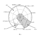
- FIG. 1 is a schematic diagram of various services provided by a 5G network according to an embodiment of the present disclosure
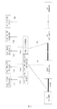
- FIG. 2 is a schematic diagram of a network structure of a 5G network according to an embodiment of the present disclosure
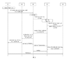
- FIG. 3 is a schematic diagram of a process of establishing a PDU session provided by the related art
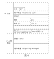
- FIG. 4 is a schematic diagram of a composition of a data packet according to an embodiment of the present disclosure.
- FIG. 5 is a schematic diagram of an interaction process involving multiple network entity interactions according to an embodiment of the present disclosure
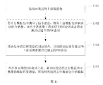
- FIG. 6 is a flowchart of a data sending method according to an embodiment of the present disclosure.
- FIG. 7 is a flowchart of a data sending method according to an embodiment of the present disclosure.
- FIG. 8 is a flowchart of a data sending method according to an embodiment of the present disclosure.
- FIG. 9 is a flowchart of a data sending method according to an embodiment of the present disclosure.
- FIG. 10 is a flowchart of a data sending method according to an embodiment of the present disclosure.
- FIG. 11 is a flowchart of a data sending method according to an embodiment of the present disclosure.
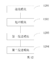
- FIG. 12 is a schematic structural diagram of a data sending apparatus according to an embodiment of the present disclosure.
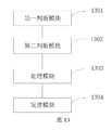
- FIG. 13 is a schematic structural diagram of a data sending apparatus according to an embodiment of the present disclosure.
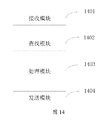
- FIG. 14 is a schematic structural diagram of a data sending apparatus according to an embodiment of the present disclosure.
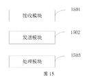
- FIG. 15 is a schematic structural diagram of a data sending apparatus according to an embodiment of the present disclosure.
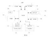
- FIG. 16 is a schematic structural diagram of a user equipment according to an embodiment of the present disclosure.
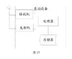
- FIG. 17 is a schematic structural diagram of a base station device according to an embodiment of the present disclosure.
- the network structure mainly includes the following network entities: UE, RAN, UPF, DN, AMF, SMF, Authentication Server Function (AUSF), and Network Capability Function (Network Exposure Function). , NEF), NF Repository Function (NRF), Policy Control Function (PCF), Unified Data Management (UDM), Application Function Interface (AF).
- NEF Network Exposure Function
- NEF NF Repository Function
- PCF Policy Control Function
- UDM Unified Data Management
- AF Application Function Interface
- the UE can be a mobile phone, the RAN is a base station device, and the UPF is a gateway device.
- the DN is the network where the network resources accessed by the UE are located.
- the UDM mainly manages the subscription information of the user, and the AF is mainly used to obtain the information of the application layer.
- the PDU session is also referred to as a PDU session in the embodiment of the present disclosure, which is a connection association between the UE and the DN, and is used to provide the UE with a connection service for accessing the DN, that is, the PDU Session can be understood as a UE.
- the PDU Session is used to determine the forwarding path of the data packet in the 5G network, as shown by the black bold portion in Figure 2, the forwarding path involves the RAN, and one or more UPFs.
- the UE allocates a Session ID of the PDU Session, and sends a PDU Session Establishment Request (Establishment Req) message to the AMF entity to trigger the establishment process of the PDU Session.
- PDU Session Establishment Request Establishment Req
- the AMF entity selects the SMF entity and forwards the PDU Session Establishment Request message to the selected SMF entity.
- the SMF entity selects the UPF, allocates the UE IP, and then sends a PDU Session Establishment Request message to the UPF.
- the UPF configures the user plane path and sends a PDU Session Establishment Response message to the SMF.
- the SMF entity sends a PDU Session Establishment Response message to the AMF entity, where the response message includes the allocated UE IP.
- the AMF entity sends a message (N2 PDU Session Req) to the RAN, and configures the user plane resource of the air interface and the path between the RAN and the UPF.
- the QoS information includes a QoS Class Identifier (QCI) and a Maximum Bit Rate (MBR).
- QCI QoS Class Identifier
- MBR Maximum Bit Rate
- the related art completes the establishment of the PDU Session by the above steps. After the establishment of the PDU Session is completed, the user plane channel between the UE and the RAN and the UPF is completely established.
- the SMF entity needs to perform UPF selection, UE IP allocation, and need to configure QoS information.
- the PDU session establishment process shown in FIG. 3 needs to be performed before data transmission, that is, in the 5G network architecture of FIG. 2, the data transmission process needs to be implemented when the PDU Session is established, which undoubtedly fails to meet the low delay requirement.
- the embodiment of the present disclosure proposes a new data transmission method. That is, the embodiment of the present disclosure can solve the problem that the existing process in the 5G network cannot meet the delay requirement of the low-latency service.
- Embodiments of the present disclosure are directed to providing a low latency service processing mechanism that can carry control plane signaling in a data packet.
- the control plane signaling can be used to indicate the establishment of the PDU session, and can also be used to trigger the Service Request process to activate the established PDU Session.
- the embodiment of the present disclosure can perform packet sending without waiting for the establishment process of the PDU Session, that is, if the PDU Session is not completed, the UE can forward the data packet by using a forwarding mechanism without a session. After the PDU Session is established, the UE uses the PDU Session-based forwarding mechanism.
- the network entity corresponding to the embodiment of the present disclosure mainly includes the UE, the RAN, the UPF, the AMF entity, and the SMF entity shown in FIG. 2.
- the UE may be referred to as a user equipment in the embodiment of the present disclosure
- the RAN may be referred to as a base station device
- the UPF may be referred to as a gateway device
- the AMF entity and the SMF entity may be referred to as a control plane device.
- software modules need to be added respectively, and the added software modules can process the signaling messages carried by the data packets and can implement the packet forwarding without the session.
- Embodiments of the present disclosure define a mechanism for carrying control plane signaling of a data packet and a packet forwarding mechanism without Session (ie, Sessionless).
- embodiments of the present disclosure extend the format of a data packet so that it can carry signaling messages.
- the data packet may also carry the information required to perform the Sessionless packet forwarding, which is referred to as a data forwarding message in the embodiment of the present disclosure.
- the data forwarding message may include slice information, path information, and QoS information. That is, the data packet may carry the slice information for selecting the UPF, and may also carry the path information for the path record and selection of the uplink and downlink, and may also carry the QoS information used for QoS guarantee in the data forwarding.
- the data packet uses the UE ID as the IP address of the user.
- the UE ID may also be referred to as identifier information of the UE.
- the IP header extends the following:
- Signaling message flag which may be referred to as a signaling message identifier, is used to identify whether the data packet carries a signaling message.
- Data forwarding info flag which may be referred to as a data forwarding information identifier, is used to identify whether the data packet carries a data forwarding message required for performing Sessionless data forwarding.
- Signaling type may be referred to as a signaling type, and may be a PDU Session Request for requesting to establish a PDU Session, and may also be a Service Request, which is not specifically limited in this embodiment of the present disclosure.
- NSSAI Network Slice Selection Assistance Information, which may be referred to as network slice selection assistance information, that is, the slice information mentioned above;
- RAN IP and UPF IP Specify or record the path of the packet.
- UE ID is the identity information of the UE, which may be the mobile subscriber number (Mobile Subscriber ISDN, MSISDN) of the user.
- IP Pref refers to the IP prefix assigned to the user by the network.
- IP payload portion shown in Figure 4 includes specific data and signaling messages.
- the second point is based on the signaling message carried by the extended data packet, and the base station device can trigger the process of establishing the PDU session or triggering the process of activating the established PDU session.
- the data packet can be sent through the Sessionless method.
- the base station device selects the UPF based on the slice information carried in the received data packet, and performs QoS control in the data forwarding process based on the carried QoS information, and records the path of the data packet.
- QoS control in the data forwarding process based on the carried QoS information
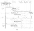
- FIG. 5 is a schematic diagram of an interaction process involving multiple network entity interactions according to an embodiment of the present disclosure.
- the main body of the interaction is a UE, a RAN, an AMF entity, an SMF entity, and an UPF.
- the interaction process between each network entity is as follows:
- the UE initiates a low-latency service, and sends the first data packet to the RAN.
- the data packet sent here is specifically an uplink data packet.
- the UE Before the UE sends the data packet, since the PDU Session has not been established, the UE needs to trigger the establishment process of the PDU Session while transmitting the data packet. That is, the data packet sent by the UE also needs to carry a signaling message for requesting to establish a PDU Session.
- the signaling message for requesting to establish a PDU session is collectively referred to as a first signaling message in the embodiment of the present disclosure.
- the data packet carries the data forwarding messages required for packet forwarding during Sessionless, such as NSSAI and QoS information.
- the UE also fills in the UE ID in the lower 64 bits of the source address of the data packet, and sets the upper 64 bits to 0.
- the RAN After receiving the data packet sent by the UE, the RAN strips the data and the signaling message from the data packet, and forwards the data packet in a Sessionless manner, and forwards the stripped signaling message to the AMF entity, and carries the data packet. Selected UPF information.
- the selected UPF may also be referred to as a target UPF in the embodiment of the present disclosure.
- the selected UPF After receiving the data packet sent by the UE, the selected UPF allocates an IP prefix to the UE, and adds an IP prefix allocated to the UE to the upper 64 bits in the source address of the data packet, and then the UPF uses the data.
- the package is issued.
- the UPF specifically sends the data packet to the DN.
- the above steps 501 to 503 are the first packet processing.
- the AMF entity and the SMF entity trigger a process of establishing a PDU session.
- the UE continues to send the data packet by using the Sessionless method.
- the AMF entity After the PDU session is established, the AMF entity returns the PDU Session setup response to the RAN, which in turn is forwarded to the UE by the RAN.
- the data packet sent by the UE is forwarded through the PDU session.
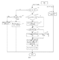
- the UE sends an uplink data packet, and determines whether the PDU session has been established. If yes, step 602 is performed; if not, step 605 is performed.
- Step 612 to step 611 are performed when the UE sends the uplink data packet, and step 612 is performed when the UE receives the downlink data packet.
- the UE status can be divided into a connected state and an idle state.
- the UE If the UE is in an idle state, the UE triggers a process of performing a Service Request.
- the UE determines whether a first signaling message for requesting to establish a PDU Session has been sent; if not, step 606 is performed; if yes, step 607 is performed.
- the UE If not sent, the UE generates a first signaling message for requesting to establish a PDU Session, and inserts the first signaling message into the uplink data packet.
- step 608 determines whether the path information has been saved. If not, step 608 is performed; if yes, step 609 is performed.
- the UE inserts the path information into the uplink data packet.
- the UE inserts the NSSAI information into the uplink data packet.
- the UE inserts QoS information in the uplink data packet, and sets the lower 64 bits of the source address in the uplink data packet to the UE ID, and the high 64 position is 0.
- the UE sends the uplink data packet to the RAN by using an air interface.
- the UE When receiving the downlink data packet, the UE records the path information carried in the downlink data packet.
- the data transmission method provided by the embodiment of the present disclosure is described above from the perspective of the UE.
- the data sending method is as follows:
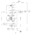
- the RAN After receiving the uplink data packet sent by the UE, the RAN determines whether the first signaling message identifier S/F in the uplink data packet is set.
- the RAN performs step 701 to step 712 when receiving the uplink data packet, and performs step 713 when the RAN receives the downlink data packet.
- the RAN If set, determine that the uplink data packet carries the first signaling message, and the RAN strips the data and the first signaling message from the uplink data packet.
- step 703. Determine whether the data forwarding information identifier D/F in the uplink data packet is set. If not, execute step 704; if yes, execute step 705.
- the PDU session is established, and data is forwarded according to the established PDU session.
- the RAN selects a corresponding routing table according to the NSSAI information carried in the uplink data packet, and searches the routing table according to the Peer IP carried in the uplink data packet to obtain a UPF of the target UPF. address.
- the routing table selected above may also be referred to as a target routing table in the embodiment of the present disclosure.
- the UPF indicated by the path information is directly used.
- the RAN records the found UPF address in the path information of the uplink data packet.
- the RAN selects a pre-built shared link to the target UPF according to the QCI information carried in the uplink data packet.
- shared links such as the GPRS Tunneling Protocol (GTP) tunnel
- GTP GPRS Tunneling Protocol
- these shared links correspond to different QCI values, and the link bandwidth is set according to the service model.
- the shared link also ensures that users can perform QoS-guaranteed data transmission within a short period of time when the PDU Session is established.
- the RAN performs bandwidth control according to the MBR value, and determines whether the forwarded uplink data packet is greater than the MBR value. If yes, step 710 is performed; if not, step 711 is performed.
- the RAN discards the uplink packet.
- the RAN forwards the uplink data packet by using the selected shared link.
- the RAN selects an AMF entity according to the NSSAI information, and forwards the first signaling message carried in the uplink data packet and the address information of the target UPF to the selected AMF entity, and initiates a PDU Session establishing process.
- the selected AMF entity is also referred to as a target AMF entity in the embodiment of the present disclosure.
- the RAN After receiving the downlink data packet, the RAN forwards the downlink data packet by using an air interface.
- the data transmission method provided by the embodiment of the present disclosure is described above from the perspective of the RAN.
- the data sending method is as follows:
- the UPF After receiving the uplink data packet forwarded by the RAN, the UPF determines whether the upper 64 bits of the source address of the uplink data packet is 0. If yes, step 802 is performed; if no, step 805 is performed.
- the UPF searches for the UE IP prefix by using the lower 64-bit UE ID; if not, proceeds to step 803; if found, proceeds to step 804.
- the UPF allocates a 64-bit UE IP prefix to the UE, saves the correspondence between the UE IP prefix and the UE ID, and inserts the UE IP prefix into the upper 64 bits of the source address.
- the UPF inserts the UE IP prefix into the upper 64 bits of the source address, and records path information of the uplink data packet.
- the UPF forwards the uplink data packet through the N6 interface.
- the UPF After receiving the downlink data packet, the UPF searches for the corresponding path information according to the 5-tuple information of the downlink data packet to obtain the RAN address.
- the UPF inserts the found path information in the downlink data packet.
- the UPF sends the downlink data packet to the corresponding RAN according to the found RAN address.
- the PDU Session establishment process provided by the embodiment of the present disclosure is as follows:
- the RAN sends, to the selected AMF entity, a first signaling message for requesting to establish a PDU Session and address information of a target UPF selected in the Sessionless data sending process.
- the selected AMF entity selects an SMF entity according to the address information of the target UPF, and forwards a first signaling message for establishing a PDU Session to the selected SMF entity.
- the selected SMF entity sends a specified message including the UE ID to the target UPF according to the address information of the target UPF.
- the specified message is generated according to the foregoing first signaling message.
- the target UPF searches for the UE IP prefix allocated to the UE according to the UE ID, and returns the found UE IP prefix to the selected SMF entity.
- the selected SMF entity records the UE IP prefix allocated to the UE, and returns it to the UE.
- the second point that needs to be explained is that the PDU Session establishment process provided by the embodiment of the present disclosure is different from that of FIG. 3 in that the RAN has already selected the UPF, and the UPF has also allocated the UE IP, so the control plane device does not need to perform the UPF again.
- the assignment of UE IP is different from that of FIG. 3 in that the RAN has already selected the UPF, and the UPF has also allocated the UE IP, so the control plane device does not need to perform the UPF again.
- the assignment of UE IP is different from that of FIG. 3 in that the RAN has already selected the UPF, and the UPF has also allocated the UE IP, so the control plane device does not need to perform the UPF again.
- the assignment of UE IP is the assignment of UE IP.
- the embodiments shown in FIG. 5 to FIG. 9 propose a method for carrying a signaling message for requesting establishment of a PDU Session along with a path in a data packet and a new method for transmitting a data packet when Sessionless.
- the data packet sent by the UE carries the foregoing signaling message and information required for data forwarding when Sessionless.
- the embodiment of the present disclosure selects the UPF by the RAN and allocates the UE IP prefix by the UPF, and finally implements forwarding of the data packet through the shared link.
- the embodiment of the present disclosure also improves the PDU Session establishment process of the control plane.
- the signaling message for requesting the establishment of the PDU Session is carried in the data packet, and the triggering of the PDU Session is established.
- the data packet is sent in the manner of Sessionless, so that the data packet can be sent in real time without establishing a PDU Session, so that the delay requirement of the low-latency service is satisfied.
- the embodiments of the present disclosure provide an implementation mechanism for a low-latency service, so that the UE does not need to wait for the PDU Session to be established before transmitting the data packet, and can better meet the low-latency service requirement of the user.
- the extra information carried in the data packet enables the transmission of the data packet to ensure the corresponding QoS during the establishment of the PDU Session, thereby ensuring the user's service experience.
- the UE does not need to perform signaling interaction with the network device in advance to establish a PDU Session before transmitting the data packet, and the session context storage requirement of the network device (such as RAN, UPF, AMF entity, SMF entity) can be reduced.
- the network device such as RAN, UPF, AMF entity, SMF entity
- the UE sends a signaling message at the same time as the data packet is sent, which reduces the number of preemption of the air interface resource, saves the air interface resource, and reduces the processing overhead of the network device.
- the process of establishing the PDU session can be triggered at the same time, so that the data transmission does not need to wait for the establishment of the PDU session, which reduces the delay of data transmission and improves the service experience of the user.
- the UE before the UE sends the uplink data packet, if the PDU session has been established, but the UE is in the idle state, the UE needs to trigger the Service Request process to activate the established data packet while transmitting the uplink data packet. PDU Session.
- embodiments of the present disclosure include a newly selected UPF and an initial UPF.
- the initial UPF that is, the UPF that assigns the UE IP, may also be referred to as an Anchor UPF.
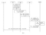
- the embodiment of the present disclosure when the UE is in the idle state, the embodiment of the present disclosure further includes the process of activating the established PDU Session shown in FIG. 10, and the specific process is as follows:
- the UE sends a first uplink data packet, where the uplink data packet carries a second signaling message for activating the established PDU session and the data is in the Sessionless state.
- the data forwarding message required for packet forwarding.
- the second signaling message includes a session ID of the PDU Session to be activated, and the data forwarding message required for packet forwarding during the Sessionless process may include path information (Anchor UPF address), QoS information, and the like. This example does not specifically limit this.
- the RAN After receiving the first uplink data packet, the RAN strips the data and the second signaling message from the data packet, and forwards the data packet by using a Sessionless method, and forwards the second signaling message to the control plane device. And carry the newly selected UPF information.
- the first uplink data packet can only be forwarded by the Sessionless method, and the RAN forwards the second signaling message to the control plane.
- the reason why the newly selected UPF information is carried is because the RAN and the Anchor UPF may not be directly reachable at this time, so the first uplink packet needs to be forwarded through the new UPF.
- the newly selected UPF forwards the first uplink data packet to the Anchor UPF according to the path information carried in the uplink data packet, and then forwards the first uplink data packet by the Anchor UPF.
- the Anchor UPF specifically forwards the first uplink data packet to the DN.
- the path information includes the specified address information, which is the address information of the initial UPF.
- the control plane device triggers the establishment of the Service Request, and in the process of establishing the Service Request, the uplink data packet is forwarded by using the Sessionless method.
- the RAN After receiving the setup response sent by the control plane device, the RAN forwards the response to the UE, and the UE is in the connected state, and performs data transmission based on the established PDU Session.
- the embodiment shown in FIG. 10 proposes a method for carrying a second signaling message of a Service Request along with a path in a data packet and a new method for transmitting a data packet by Sessionless.
- the second signaling message of the Service Request is carried in the data packet, so that when the Service Request process is triggered, the data packet can be sent through the Sessionless method, and the data packet is established.
- the PDU session can be activated through the Service Request process.
- the data can be sent in real time to meet the low latency requirement.
- FIG. 11 is a flowchart of a data sending method according to an embodiment of the present disclosure. Referring to FIG. 11, the method provided by the embodiment of the present disclosure is as follows:
- the uplink data packet carries the signaling message
- the signaling message is stripped from the uplink data packet, where the signaling message is used to request to establish a PDU session or request to activate an established PDU session.
- the UE before the presence of an available PDU session, the UE carries an additional signal in addition to the signaling message for requesting to establish a PDU session or requesting activation of an established PDU session.
- Carrying the data forwarding message so that when the PDU session establishment process or the PDU session activation process is triggered, the data transmission message carried by the data packet can also be used for data transmission, thereby realizing real-time in the absence of an available PDU session.
- Sending data packets greatly meets the latency requirements of low latency services.
- FIG. 12 is a schematic structural diagram of a data sending apparatus according to an embodiment of the present disclosure. The method is applied to a base station apparatus. Referring to FIG. 12, the apparatus includes:
- the receiving module 1201 is configured to receive an uplink data packet sent by the UE.
- the processing module 1202 is configured to: if the uplink data packet carries a signaling message, strip the signaling message from the uplink data packet, where the signaling message is used to request to establish a PDU session or request activation is established. PDU session;
- the first sending module 1203 is configured to forward the signaling message to the control plane device, so that the control plane device establishes a PDU session or activates an established PDU session.
- the second sending module 1204 is configured to forward data in the uplink data packet sent by the UE, based on a data forwarding message carried in the uplink data packet sent by the UE, before the available PDU session exists.
- the apparatus in addition to carrying a signaling message for requesting to establish a PDU session or requesting activation of an established PDU session, in addition to carrying a signaling message in the data packet before the available PDU session exists, Carrying the data forwarding message, so that when the PDU session establishment process or the PDU session activation process is triggered, the data transmission message carried by the data packet can also be used for data transmission, thereby realizing real-time in the absence of an available PDU session. Sending data packets greatly meets the latency requirements of low latency services.
- the second sending module is configured to determine whether the path information of the uplink data packet is included in the data forwarding message, and if the path information is included, according to the data forwarding message, The service quality QoS class number, the shared link between the base station device and the target UPF, the target UPF being the UPF indicated by the path information, and forwarding the uplink to the target UPF through the shared link The data in the packet.
- the second sending module is configured to determine whether the path information of the uplink data packet is included in the data forwarding message; if the path information is not included, forwarding the message according to the data Included NSSAI, performing target routing table selection; performing a lookup in the target routing table according to the IP address of the communication peer carried in the uplink data packet to obtain a target UPF; and forwarding the QoS category included in the message according to the data And determining a shared link between the base station device and the target UPF; and forwarding data in the uplink data packet to the target UPF by using the shared link.
- the second sending module is configured to determine whether the uplink data packet is smaller than a set MBR value, and if the uplink data packet is smaller than a set MBR value, The target UPF forwards data in the uplink data packet.
- the first sending module is configured to perform target AMF entity selection according to the NSSAI included in the data forwarding message, and forward the signaling message to the target AMF entity.
- the first sending module is further configured to perform target AMF entity selection according to the NSSAI included in the data forwarding message, and forward the address information of the target UPF to the target AMF entity.
- FIG. 13 is a schematic structural diagram of a data sending apparatus according to an embodiment of the present disclosure. The method is applied to a UE. Referring to FIG. 13, the apparatus includes:
- the first determining module 1301 is configured to determine whether a PDU session has been established.
- the second determining module 1302 is configured to determine, if the PDU session is not established, whether a first signaling message has been sent, where the first signaling message is used to request to establish the PDU session;
- the processing module 1303 is configured to: if the first signaling information is not sent, insert the generated first signaling message into the uplink data packet to be sent;
- the processing module 1303 is further configured to insert a data forwarding message in the uplink data packet to be sent;
- a sending module 1304, configured to send the uplink data packet to a base station device, where the base station device is configured to forward the first signaling message to a control plane device, and before the PDU session is established, based on the The data forwarding message carried in the uplink data packet sent by the UE forwards the data in the uplink data packet sent by the UE.
- the UE in addition to carrying a signaling message for requesting to establish a PDU session, in addition to carrying a signaling message for requesting to establish a PDU session, the UE further carries a data forwarding message, which is triggered in the presence of an available PDU session. While the PDU session is established, the data can be sent through the data forwarding message carried by the data packet, so that the data packet can be sent in real time without the available PDU session, which greatly satisfies the low latency service. Delay demand.
- the device further includes:
- a third determining module configured to determine, if the PDU session has been established, whether the UE is in an idle state
- the processing module is further configured to: if the UE is in an idle state, insert a second signaling message into an uplink data packet to be sent, where the second signaling message is used to request to activate an established PDU session;
- the processing module is further configured to insert a data forwarding message in the uplink data packet to be sent;
- the sending module is further configured to send the uplink data packet to the base station device, where the base station device is configured to forward the second signaling message to the control plane device, and before the PDU session activation is completed, based on the The data forwarding message carried in the uplink data packet sent by the UE forwards the data in the uplink data packet sent by the UE.
- the processing module is further configured to determine whether the path information of the uplink data packet has been saved; if the path information has been saved, insert the path information into the uplink data packet. If the path information is not saved, the NSSAI is inserted into the uplink data packet; QoS information is inserted into the uplink data packet, where the QoS information includes a QoS class number, an MBR value; and the uplink data packet is The lower N bits of the source address are set to the identification information of the UE; the high N bits of the source address of the uplink data packet are set to a preset value.
- FIG. 14 is a schematic structural diagram of a data sending apparatus according to an embodiment of the present disclosure, which is applied to a UPF.
- the apparatus includes:
- the receiving module 1401 is configured to receive data in an uplink data packet that is forwarded by the UE to the base station device, where the uplink data packet includes a first signaling message for requesting to establish a PDU session.
- the searching module 1402 is configured to: if a high N bit in the source address of the uplink data packet is a preset value, search for a network protocol IP prefix of the UE according to a low N bit in the source address;
- the processing module 1403 is configured to insert the IP prefix into a high N bit in the source address if the IP prefix is found;
- the processing module 1403 is further configured to record path information of the uplink data packet.
- the sending module 1404 is configured to forward data in the uplink data packet.
- the apparatus in addition to carrying a signaling message for requesting to establish a PDU session or requesting activation of an established PDU session, in addition to carrying a signaling message in the data packet before the available PDU session exists, Carrying the data forwarding message, so that when the PDU session establishment process or the PDU session activation process is triggered, the data transmission message carried by the data packet can also be used for data transmission, thereby realizing real-time in the absence of an available PDU session. Sending data packets greatly meets the latency requirements of low latency services.
- the processing module is further configured to allocate an N-bit IP prefix to the UE if the IP prefix is not found, and insert the allocated IP prefix into the high address in the source address. a bit; recording a correspondence between the allocated IP prefix and the identification information of the UE.
- the receiving module is further configured to receive data in an uplink data packet that is forwarded by the UE to the base station device, where the uplink data packet includes a second request for requesting activation of the established PDU session.
- the sending module is further configured to: forward the data in the uplink data packet to the initial UPF according to the specified address information included in the path information of the uplink data packet, so that the initial UPF sends the uplink data packet The data in it is forwarded;
- the specified address information is address information of the initial UPF, and the initial UPF refers to an UPF that allocates an IP prefix to the UE.
- the apparatus includes:
- the receiving module 1501 is configured to receive a first signaling message forwarded by the target AMF entity and address information of the target UPF, where the target AMF entity is configured to determine the target SMF entity after receiving the address information sent by the base station device, and Sending, by the target SMF entity, the first signaling message and the address information;
- the sending module 1502 is configured to send, according to the address information, a specified message that includes the identifier information of the user equipment UE to the target UPF, so that the target UPF searches for the UE that is allocated to the UE according to the identifier information of the UE.
- An IP prefix, the specified message is generated according to the first signaling message;
- the receiving module 1501 is further configured to receive an IP prefix of the UE returned by the target UPF;
- the processing module 1503 is configured to record an IP prefix of the UE.
- the sending module 1502 is further configured to return the IP prefix to the UE.
- the apparatus in addition to carrying a signaling message for requesting to establish a PDU session or requesting activation of an established PDU session, in addition to carrying a signaling message in the data packet before the available PDU session exists, Carrying the data forwarding message, so that when the PDU session establishment process or the PDU session activation process is triggered, the data transmission message carried by the data packet can also be used for data transmission, thereby realizing real-time in the absence of an available PDU session. Sending data packets greatly meets the latency requirements of low latency services.
- the embodiment of the present disclosure provides a user equipment, which can be used to perform the data sending method provided in the foregoing embodiments.
- the user equipment 1600 includes:
- the user equipment 1600 can include a radio frequency (RF) circuit 110, a memory 120 including one or more computer readable storage media, an input unit 130, a display unit 140, a sensor 150, an audio circuit 160, and wireless fidelity (Wireless).
- RF radio frequency
- a Fidelity, WiFi) module 170 a processor 180 including one or more processing cores, and a power supply 190 and the like.
- FIG. 16 does not constitute a limitation to the user equipment, and may include more or less components than those illustrated, or some components may be combined, or different component arrangements. among them:
- the RF circuit 110 can be used for transmitting and receiving information or during a call, and receiving and transmitting signals. Specifically, after receiving downlink information of the base station, the downlink information is processed by one or more processors 180. In addition, the data related to the uplink is sent to the base station. .
- the RF circuit 110 includes, but is not limited to, an antenna, at least one amplifier, a tuner, one or more oscillators, a Subscriber Identity Module (SIM) card, a transceiver, a coupler, and a Low Noise Amplifier (LNA). , duplexer, etc.
- RF circuitry 110 can also communicate with the network and other devices via wireless communication.
- the wireless communication may use any communication standard or protocol, including but not limited to Global System of Mobile communication (GSM), General Packet Radio Service (GPRS), Code Division Multiple Access (Code). Division Multiple Access (CDMA), Wideband Code Division Multiple Access (WCDMA), Long Term Evolution (LTE), E-mail, Short Messaging Service (SMS), etc.
- GSM Global System of Mobile communication
- GPRS General Packet Radio Service
- Code Division Multiple Access Code Division Multiple Access
- CDMA Code Division Multiple Access
- WCDMA Wideband Code Division Multiple Access
- LTE Long Term Evolution
- E-mail Short Messaging Service
- the memory 120 can be used to store software programs and modules, and the processor 180 executes various functional applications and data processing by running software programs and modules stored in the memory 120.
- the memory 120 may mainly include a storage program area and a storage data area, wherein the storage program area may store an operating system, an application required for at least one function (such as a sound playing function, an image playing function, etc.), and the like; the storage data area may be stored according to Data created by the use of the user device 1600 (such as audio data, phone book, etc.), and the like.
- memory 120 can include high speed random access memory, and can also include non-volatile memory, such as at least one magnetic disk storage device, flash memory device, or other volatile solid state storage device. Accordingly, memory 120 may also include a memory controller to provide access to memory 120 by processor 180 and input unit 130.
- the input unit 130 can be configured to receive input numeric or character information and to generate keyboard, mouse, joystick, optical or trackball signal inputs related to user settings and function controls.
- input unit 130 can include touch-sensitive surface 131 as well as other input devices 132.
- Touch-sensitive surface 131 also referred to as a touch display or trackpad, can collect touch operations on or near the user (such as a user using a finger, stylus, etc., on any suitable object or accessory on touch-sensitive surface 131 or The operation near the touch-sensitive surface 131) and driving the corresponding connecting device according to a preset program.
- the touch-sensitive surface 131 can include two portions of a touch detection device and a touch controller.
- the touch detection device detects the touch orientation of the user, and detects a signal brought by the touch operation, and transmits the signal to the touch controller; the touch controller receives the touch information from the touch detection device, converts the touch information into contact coordinates, and sends the touch information.
- the processor 180 is provided and can receive commands from the processor 180 and execute them.
- the touch-sensitive surface 131 can be implemented in various types such as resistive, capacitive, infrared, and surface acoustic waves.
- the input unit 130 can also include other input devices 132.
- other input devices 132 may include, but are not limited to, one or more of a physical keyboard, function keys (such as volume control buttons, switch buttons, etc.), trackballs, mice, joysticks, and the like.
- Display unit 140 can be used to display information entered by the user or information provided to the user as well as various graphical user interfaces of user device 1600, which can be composed of graphics, text, icons, video, and any combination thereof.
- the display unit 140 may include a display panel 141.
- the display panel 141 may be configured in the form of a liquid crystal display (LCD), an organic light-emitting diode (OLED), or the like.
- the touch-sensitive surface 131 may cover the display panel 141, and when the touch-sensitive surface 131 detects a touch operation thereon or nearby, it is transmitted to the processor 180 to determine the type of the touch event, and then the processor 180 according to the touch event The type provides a corresponding visual output on display panel 141.
- touch-sensitive surface 131 and display panel 141 are implemented as two separate components to implement input and input functions, in some embodiments, touch-sensitive surface 131 can be integrated with display panel 141 for input. And output function.
- User device 1600 may also include at least one type of sensor 150, such as a light sensor, motion sensor, and other sensors.
- the light sensor may include an ambient light sensor and a proximity sensor, wherein the ambient light sensor may adjust the brightness of the display panel 141 according to the brightness of the ambient light, and the proximity sensor may close the display panel 141 when the user device 1600 moves to the ear. And / or backlight.
- the gravity acceleration sensor can detect the magnitude of acceleration in all directions (usually three axes). When it is stationary, it can detect the magnitude and direction of gravity.
- the gesture of the mobile phone can be used to identify the gesture of the mobile phone (such as horizontal and vertical screen switching, related Game, magnetometer attitude calibration), vibration recognition related functions (such as pedometer, tapping), etc.; as for the user equipment 1600 can also be configured with gyroscopes, barometers, hygrometers, thermometers, infrared sensors and other sensors, here No longer.
- the audio circuit 160, the speaker 161, and the microphone 162 can provide an audio interface between the user and the user device 1600.
- the audio circuit 160 can transmit the converted electrical data of the received audio data to the speaker 161 for conversion to the sound signal output by the speaker 161; on the other hand, the microphone 162 converts the collected sound signal into an electrical signal by the audio circuit 160. After receiving, it is converted into audio data, and then processed by the audio data output processor 180, sent to the other user equipment via the RF circuit 110, or outputted to the memory 120 for further processing.
- the audio circuit 160 may also include an earbud jack to provide communication of the peripheral earphones with the user device 1600.
- WiFi is a short-range wireless transmission technology
- the user equipment 1600 can help users to send and receive emails, browse web pages, and access streaming media through the WiFi module 170, which provides wireless broadband Internet access for users.
- FIG. 16 shows the WiFi module 170, it can be understood that it does not belong to the essential configuration of the user equipment 1600, and may be omitted as needed within the scope of not changing the essence of the invention.
- the processor 180 is the control center of the user device 1600, connecting various portions of the entire handset with various interfaces and lines, by running or executing software programs and/or modules stored in the memory 120, and recalling data stored in the memory 120.
- the various functions and processing data of the user equipment 1600 are executed to perform overall monitoring of the mobile phone.
- the processor 180 may include one or more processing cores; optionally, the processor 180 may integrate an application processor and a modem processor, where the application processor mainly processes an operating system, a user interface, and an application. Etc.
- the modem processor primarily handles wireless communications. It can be understood that the above modem processor may not be integrated into the processor 180.
- the user equipment 1600 also includes a power supply 190 (such as a battery) that supplies power to the various components.
- a power supply 190 (such as a battery) that supplies power to the various components.
- the power supply can be logically coupled to the processor 180 through the power management system to manage charging, discharging, and power management through the power management system.
- Power supply 190 may also include any one or more of a DC or AC power source, a recharging system, a power failure detection circuit, a power converter or inverter, a power status indicator, and the like.
- the user equipment 1600 may further include a camera, a Bluetooth module, and the like, and details are not described herein again.
- the display unit of the user equipment is a touch screen display
- the user equipment further includes a memory, and one or more programs, wherein one or more programs are stored in the memory and configured to be one or one The above processor executes.
- a storage medium storing a computer program, such as a memory storing a computer program, which when executed by the processor implements a data transmission method performed by the UE in the following embodiments.
- the storage medium may be a read-only memory (ROM), a random access memory (RAM), a compact disc read-only memory (CD-ROM), or an optical data storage. Equipment, etc.
- FIG. 17 is a structural block diagram of a base station device according to an embodiment of the present disclosure.
- the base station can include a transmitter, a receiver, a memory, and a processor coupled to the transmitter, the receiver, and the memory, respectively.
- the base station device may further include a common component such as an antenna, a baseband processing component, a medium RF processing component, an input/output device, and the like, and the embodiment of the present disclosure is not limited herein.
- a storage medium storing a computer program, such as a memory storing a computer program, when the computer program is executed by the processor, implementing a data transmission method executed by the base station device in the following embodiments .
- the storage medium may be a ROM, a RAM, a CD-ROM, an optical data storage device, or the like.
- a user plane network element is provided in another exemplary embodiment.
- the user plane network element can include a transmitting unit, a receiving unit, a memory, and a processor coupled to the transmitting unit, the receiving unit, and the memory, respectively.
- a storage medium storing a computer program such as a memory storing a computer program, which is executed by the processor, implements a data transmission method executed by the user plane network element in the following embodiment.
- the storage medium may be a ROM, a RAM, a CD-ROM, an optical data storage device, or the like.
- an SMF entity in another exemplary embodiment, can include a transmitting unit, a receiving unit, a memory, and a processor coupled to the transmitting unit, the receiving unit, and the memory, respectively.
- a storage medium storing a computer program, such as a memory storing a computer program, which when executed by the processor implements a data transmission method executed by an SMF entity in the following embodiments.
- the storage medium may be a ROM, a RAM, a CD-ROM, an optical data storage device, or the like.
- a person skilled in the art may understand that all or part of the steps of implementing the above embodiments may be completed by hardware, or may be instructed by a program to execute related hardware, and the program may be stored in a computer readable storage medium.
- the storage medium mentioned may be a read only memory, a magnetic disk or an optical disk or the like.
Landscapes
- Engineering & Computer Science (AREA)
- Computer Networks & Wireless Communication (AREA)
- Signal Processing (AREA)
- Quality & Reliability (AREA)
- Mobile Radio Communication Systems (AREA)
Priority Applications (2)
| Application Number | Priority Date | Filing Date | Title |
|---|---|---|---|
| EP18893444.2A EP3672319B1 (de) | 2017-12-28 | 2018-12-05 | Datensendeverfahren, -vorrichtung und -system |
| US16/832,524 US11627486B2 (en) | 2017-12-28 | 2020-03-27 | Data sending method and apparatus, and device |
Applications Claiming Priority (2)
| Application Number | Priority Date | Filing Date | Title |
|---|---|---|---|
| CN201711457744.6A CN109982383B (zh) | 2017-12-28 | 2017-12-28 | 数据发送方法、装置及设备 |
| CN201711457744.6 | 2017-12-28 |
Related Child Applications (1)
| Application Number | Title | Priority Date | Filing Date |
|---|---|---|---|
| US16/832,524 Continuation US11627486B2 (en) | 2017-12-28 | 2020-03-27 | Data sending method and apparatus, and device |
Publications (1)
| Publication Number | Publication Date |
|---|---|
| WO2019128657A1 true WO2019128657A1 (zh) | 2019-07-04 |
Family
ID=67066450
Family Applications (1)
| Application Number | Title | Priority Date | Filing Date |
|---|---|---|---|
| PCT/CN2018/119338 Ceased WO2019128657A1 (zh) | 2017-12-28 | 2018-12-05 | 数据发送方法、装置及设备 |
Country Status (4)
| Country | Link |
|---|---|
| US (1) | US11627486B2 (de) |
| EP (1) | EP3672319B1 (de) |
| CN (1) | CN109982383B (de) |
| WO (1) | WO2019128657A1 (de) |
Cited By (4)
| Publication number | Priority date | Publication date | Assignee | Title |
|---|---|---|---|---|
| WO2021155938A1 (en) * | 2020-02-06 | 2021-08-12 | Telefonaktiebolaget Lm Ericsson (Publ) | User plane function selection in a communications network |
| CN113411834A (zh) * | 2020-03-17 | 2021-09-17 | 华为技术有限公司 | 报文处理方法、装置、设备及存储介质 |
| WO2022110184A1 (zh) * | 2020-11-30 | 2022-06-02 | 华为技术有限公司 | 一种通信方法、装置及系统 |
| US12389467B2 (en) | 2020-02-06 | 2025-08-12 | Telefonaktiebolaget Lm Ericsson (Publ) | Tunnel initiation in a communications network |
Families Citing this family (7)
| Publication number | Priority date | Publication date | Assignee | Title |
|---|---|---|---|---|
| CN111405682B (zh) * | 2020-03-19 | 2024-04-16 | 中国联合网络通信集团有限公司 | 一种数据转发方法及网关 |
| US12549635B2 (en) * | 2021-02-11 | 2026-02-10 | Verizon Patent And Licensing Inc. | Systems and methods for exposing user equipment identities to applications |
| FR3119962A1 (fr) * | 2021-02-12 | 2022-08-19 | Orange | Transmission de données d’un réseau de communication vers un équipement utilisateur |
| CN113068223B (zh) * | 2021-02-24 | 2022-05-17 | 深圳市日海飞信信息系统技术有限公司 | 基于切片信息的本地分流方法、装置、设备及存储介质 |
| CN113316098B (zh) * | 2021-04-20 | 2022-10-21 | 新华三技术有限公司 | 一种建立业务通道、公网对讲的方法和公网对讲设备 |
| CN115225620A (zh) * | 2022-07-14 | 2022-10-21 | 潍柴动力股份有限公司 | 一种报文转发方法及装置 |
| CN118827334B (zh) * | 2023-08-29 | 2026-01-06 | 中国移动通信有限公司研究院 | 消息传输方法、装置、电子设备及存储介质 |
Citations (5)
| Publication number | Priority date | Publication date | Assignee | Title |
|---|---|---|---|---|
| WO2015013869A1 (zh) * | 2013-07-29 | 2015-02-05 | 富士通株式会社 | 传输机制的转换方法、用户设备以及基站 |
| US20170086221A1 (en) * | 2015-09-23 | 2017-03-23 | At&T Intellectual Property I, L.P. | Methods and apparatus to transmit data in a connectionless mode |
| CN107006045A (zh) * | 2014-11-18 | 2017-08-01 | 华为技术有限公司 | 网络地址中依赖于传输设备的上下文 |
| CN107018542A (zh) * | 2017-03-27 | 2017-08-04 | 中兴通讯股份有限公司 | 网络系统中状态信息的处理方法、装置及存储介质 |
| CN107241764A (zh) * | 2016-03-29 | 2017-10-10 | 电信科学技术研究院 | 一种上行、下行小数据传输方法及装置 |
Family Cites Families (16)
| Publication number | Priority date | Publication date | Assignee | Title |
|---|---|---|---|---|
| US20110194433A1 (en) | 2010-02-05 | 2011-08-11 | Qualcomm Incorporated | Managing dedicated channel resource allocation to user equipment based on radio bearer traffic within a wireless communications system |
| US9203751B2 (en) * | 2010-12-21 | 2015-12-01 | Telefonaktiebolaget L M Ericsson (Publ) | IP fragmentation in GTP tunnel |
| US8565756B2 (en) * | 2011-01-07 | 2013-10-22 | Apple Inc. | Control of measurement messaging in a mobile device |
| US8913748B2 (en) * | 2011-07-05 | 2014-12-16 | Texas Instruments Incorporated | Methods to improve bluetooth low energy performance |
| CN102547592B (zh) * | 2012-01-06 | 2015-02-18 | 电信科学技术研究院 | 一种数据传输方法及装置 |
| EP3308515A1 (de) * | 2015-06-10 | 2018-04-18 | Telefonaktiebolaget LM Ericsson (publ) | Schutz von iaps von ddos-angriffen |
| CN113556811B (zh) | 2016-05-13 | 2024-04-05 | 北京三星通信技术研究有限公司 | 一种轻连接控制的方法及设备 |
| US10362511B2 (en) * | 2016-05-17 | 2019-07-23 | Lg Electronics Inc. | Method and apparatus for determining PDU session identity in wireless communication system |
| CN107396356A (zh) * | 2016-05-17 | 2017-11-24 | 中兴通讯股份有限公司 | 数据发送方法及装置 |
| US10716083B2 (en) * | 2016-12-15 | 2020-07-14 | Lg Electronics Inc. | Tracking area assignment method in wireless communication system and device therefor |
| US10524166B2 (en) * | 2017-01-09 | 2019-12-31 | Lg Electronics Inc. | Method for interworking between networks in wireless communication system and apparatus thereof |
| US10986516B2 (en) * | 2017-03-10 | 2021-04-20 | Huawei Technologies Co., Ltd. | System and method of network policy optimization |
| CN110431859B (zh) * | 2017-03-20 | 2022-04-15 | Lg电子株式会社 | 用于无线通信系统中层之间交互的方法及其设备 |
| EP3471470B1 (de) * | 2017-06-15 | 2021-03-31 | LG Electronics Inc. -1- | Verfahren zur beantwortung einer anfrage und netzwerkvorrichtung |
| EP3641423B1 (de) * | 2017-06-17 | 2022-04-20 | LG Electronics Inc. | Verfahren zur registrierung eines endgeräts in einem drahtloskommunikationssystem und vorrichtung dafür |
| US10855814B2 (en) * | 2017-10-20 | 2020-12-01 | Comcast Cable Communications, Llc | Non-access stratum capability information |
-
2017
- 2017-12-28 CN CN201711457744.6A patent/CN109982383B/zh active Active
-
2018
- 2018-12-05 WO PCT/CN2018/119338 patent/WO2019128657A1/zh not_active Ceased
- 2018-12-05 EP EP18893444.2A patent/EP3672319B1/de active Active
-
2020
- 2020-03-27 US US16/832,524 patent/US11627486B2/en active Active
Patent Citations (5)
| Publication number | Priority date | Publication date | Assignee | Title |
|---|---|---|---|---|
| WO2015013869A1 (zh) * | 2013-07-29 | 2015-02-05 | 富士通株式会社 | 传输机制的转换方法、用户设备以及基站 |
| CN107006045A (zh) * | 2014-11-18 | 2017-08-01 | 华为技术有限公司 | 网络地址中依赖于传输设备的上下文 |
| US20170086221A1 (en) * | 2015-09-23 | 2017-03-23 | At&T Intellectual Property I, L.P. | Methods and apparatus to transmit data in a connectionless mode |
| CN107241764A (zh) * | 2016-03-29 | 2017-10-10 | 电信科学技术研究院 | 一种上行、下行小数据传输方法及装置 |
| CN107018542A (zh) * | 2017-03-27 | 2017-08-04 | 中兴通讯股份有限公司 | 网络系统中状态信息的处理方法、装置及存储介质 |
Non-Patent Citations (1)
| Title |
|---|
| SAMSUNG: "Connection-less UP and DL PDU transfer", 3GPP SA WG2 MEETING #116 S2-163579, 5 July 2016 (2016-07-05), XP051121269 * |
Cited By (7)
| Publication number | Priority date | Publication date | Assignee | Title |
|---|---|---|---|---|
| WO2021155938A1 (en) * | 2020-02-06 | 2021-08-12 | Telefonaktiebolaget Lm Ericsson (Publ) | User plane function selection in a communications network |
| US12389467B2 (en) | 2020-02-06 | 2025-08-12 | Telefonaktiebolaget Lm Ericsson (Publ) | Tunnel initiation in a communications network |
| CN113411834A (zh) * | 2020-03-17 | 2021-09-17 | 华为技术有限公司 | 报文处理方法、装置、设备及存储介质 |
| CN113411834B (zh) * | 2020-03-17 | 2023-05-09 | 华为技术有限公司 | 报文处理方法、装置、设备及存储介质 |
| US11870690B2 (en) | 2020-03-17 | 2024-01-09 | Huawei Technologies Co., Ltd. | Packet processing method and apparatus, device, and storage medium |
| US12155568B2 (en) | 2020-03-17 | 2024-11-26 | Huawei Technologies Co., Ltd. | Packet processing method and apparatus, device, and storage medium |
| WO2022110184A1 (zh) * | 2020-11-30 | 2022-06-02 | 华为技术有限公司 | 一种通信方法、装置及系统 |
Also Published As
| Publication number | Publication date |
|---|---|
| CN109982383A (zh) | 2019-07-05 |
| EP3672319B1 (de) | 2023-09-27 |
| EP3672319A1 (de) | 2020-06-24 |
| US20200229024A1 (en) | 2020-07-16 |
| EP3672319A4 (de) | 2021-08-18 |
| CN109982383B (zh) | 2020-10-09 |
| US11627486B2 (en) | 2023-04-11 |
Similar Documents
| Publication | Publication Date | Title |
|---|---|---|
| US11627486B2 (en) | Data sending method and apparatus, and device | |
| CN114845294B (zh) | 数据传送的保障方法及通信设备 | |
| CN110036661B (zh) | 一种上行数据传输方法、终端、网络侧设备及系统 | |
| KR102570017B1 (ko) | 세션 관리 방법 및 장치 | |
| US11258708B2 (en) | Communication method and communications apparatus | |
| CN109005527B (zh) | 一种数据传输方法和终端 | |
| CN110583087B (zh) | 调度请求传输控制方法及相关产品 | |
| EP3706462B1 (de) | Verfahren, benutzergerät und computerlesbares speichermedium zur verbesserung der netzwerkleistung | |
| CN108632890B (zh) | 数据传输方法和终端设备 | |
| CN111800794A (zh) | 解调参考信号位置的确定方法及设备 | |
| TWI678903B (zh) | 一種上行資料傳輸方法及終端 | |
| CN108811146B (zh) | 上行调度请求处理方法及装置 | |
| CN114946215B (zh) | 一种业务流的处理方法及设备 | |
| CN111641976A (zh) | 一种数据传输的方法、终端设备及网络设备 | |
| CN111800832B (zh) | 数据发送方法、用户设备ue及介质 | |
| CN111194085B (zh) | 一种通道资源的控制方法、终端和通信网元 | |
| CN110022584B (zh) | 承载标识控制方法、终端设备和网络单元 | |
| CN111885735B (zh) | 一种上行调度指示方法、终端设备及网络设备 | |
| CN110475302A (zh) | 一种语音业务处理方法及终端设备 | |
| WO2018170837A1 (zh) | 一种上行数据传输方法、终端、网络侧设备及系统 | |
| CN119946569A (zh) | 处理方法、智能终端及存储介质 | |
| CN111642034A (zh) | 一种数据传输的方法、终端设备以及网络设备 | |
| WO2018228605A1 (zh) | 数据传输方法、发送设备和接收设备 | |
| WO2018201412A1 (zh) | 无线链路层的数据包切割配置方法及相关产品 | |
| WO2018068319A1 (zh) | 多宿主场景下进行路由的方法及装置 |
Legal Events
| Date | Code | Title | Description |
|---|---|---|---|
| 121 | Ep: the epo has been informed by wipo that ep was designated in this application |
Ref document number: 18893444 Country of ref document: EP Kind code of ref document: A1 |
|
| ENP | Entry into the national phase |
Ref document number: 2018893444 Country of ref document: EP Effective date: 20200316 |
|
| NENP | Non-entry into the national phase |
Ref country code: DE |