WO2019129680A1 - Bride porteuse - Google Patents
Bride porteuse Download PDFInfo
- Publication number
- WO2019129680A1 WO2019129680A1 PCT/EP2018/086471 EP2018086471W WO2019129680A1 WO 2019129680 A1 WO2019129680 A1 WO 2019129680A1 EP 2018086471 W EP2018086471 W EP 2018086471W WO 2019129680 A1 WO2019129680 A1 WO 2019129680A1
- Authority
- WO
- WIPO (PCT)
- Prior art keywords
- hole
- support arm
- motor
- bracket
- bearing
- Prior art date
- Legal status (The legal status is an assumption and is not a legal conclusion. Google has not performed a legal analysis and makes no representation as to the accuracy of the status listed.)
- Ceased
Links
Images

Classifications
-
- D—TEXTILES; PAPER
- D06—TREATMENT OF TEXTILES OR THE LIKE; LAUNDERING; FLEXIBLE MATERIALS NOT OTHERWISE PROVIDED FOR
- D06F—LAUNDERING, DRYING, IRONING, PRESSING OR FOLDING TEXTILE ARTICLES
- D06F37/00—Details specific to washing machines covered by groups D06F21/00 - D06F25/00
- D06F37/20—Mountings, e.g. resilient mountings, for the rotary receptacle, motor, tub or casing; Preventing or damping vibrations
- D06F37/206—Mounting of motor
-
- D—TEXTILES; PAPER
- D06—TREATMENT OF TEXTILES OR THE LIKE; LAUNDERING; FLEXIBLE MATERIALS NOT OTHERWISE PROVIDED FOR
- D06F—LAUNDERING, DRYING, IRONING, PRESSING OR FOLDING TEXTILE ARTICLES
- D06F58/00—Domestic laundry dryers
- D06F58/02—Domestic laundry dryers having dryer drums rotating about a horizontal axis
- D06F58/04—Details
- D06F58/08—Driving arrangements
-
- H—ELECTRICITY
- H02—GENERATION; CONVERSION OR DISTRIBUTION OF ELECTRIC POWER
- H02K—DYNAMO-ELECTRIC MACHINES
- H02K5/00—Casings; Enclosures; Supports
- H02K5/04—Casings or enclosures characterised by the shape, form or construction thereof
- H02K5/16—Means for supporting bearings, e.g. insulating supports or means for fitting bearings in the bearing-shields
- H02K5/161—Means for supporting bearings, e.g. insulating supports or means for fitting bearings in the bearing-shields radially supporting the rotary shaft at both ends of the rotor
Definitions
- the present invention relates to a bearing clamp enabling fastening an electric engine used in domestic appliances or various other fields, to damp the vibration generated by said electric engine.
- drying of laundry items is essentially performed by passing heated air through the laundry items, and transmission/diffusion of the humidity of the laundry items to hot air.
- the heated air passes through the damp laundry items in a drum, absorbs the humidity of the laundry items and leaves the drum.
- the humid air leaving a drum is cooled by various methods depending on the type of the dryer, reducing its moisture holding capacity.
- the humidity of the air is condensed. Humidity is condensed by cooling the humid circulation air by passing it through the evaporator if the dryer is of the heat pump type, or by means of the cold air drawn from the environment if the dryer is of the condenser type.
- a motor In a dryer, a motor is used to rotate a drum and for a process fan to drive air flow.
- the rotation of the drum and the fan can be driven by a single motor as well as by separate motors.
- the drum and the fan are driven by a single motor, the drum is rotated by a belt and pulley assembly and the fan by coupling it to the shaft end of the motor.
- the motor is coupled to the feet provided on a chassis by bearing clamps.
- the motors used in domestic appliances are capable of revolving in high velocities, becoming a very significant source of vibration. All vibration generated by the motor is transmitted to the chassis if the motor is not beared correctly, if it is not correctly positioned on the chassis, and if its coupling points do not exhibit required rigidity.
- the aim of the present invention is to realize a bearing clamp which can be attached and detached easily.
- Another aim of the present invention is to realize a bearing clamp inhibiting vibration of an electric motor by fastening it stably.
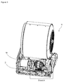
- Figure 1 is a schematic view of the bearing clamp.
- Figure 2 is a perspective view of the detail A.
- Figure 3 is a perspective view of the detail A without the motor.
- Figure 4 is a perspective view of the detail B.
- a bearing clamp (1) for motors (M) provided in domestic appliances comprises
- the bearing clamp (1) of the invention comprises a chassis (2) in which the essential parts and components of the system are placed.
- Two support arms (3) extend from the chassis (2) for placement of the motor (M).
- a semi-circular seat (31) is provided on the support arms (3) for placement of the motor (M) therein.
- a first hole (32) is provided on one of the support arms (3).
- the first hole (32) is provided on one of the extensions forming due to the semi-circular shape of the seat (31).
- a screw thread is provided in the first hole (32).
- An engagement aperture (33) is provided on the support arm (3).
- the engagement aperture (33) is provided on the other one of the extensions forming due to the semi-circular shape of the seat (31).
- a bracket (4) is provided, enclosing the motor (M) placed in the seat (31) and settling on a support arm (3).
- a bearing protrusion (41) extends from the bracket.
- a second hole (42) is provided on the bearing protrusion (41) and the second hole is positioned so as to be concentric with the first hole (31).
- a coupling member (5) is used to interconnect the first hole (32) and the second hole (42).
- An engaging projection (43) is provided, extending from the bracket (4) and fitting into the engagement aperture (32).
- a support projection (44) extends from the bracket (4), enabling keeping the bracket (4) steadfast during vibration of the motor (M) by engaging the support arm (3).
- the bearing protrusion (41) enables keeping the bracket (4) steadfast during vibration of the motor (M) by engaging the support arm (3).
- a bracket (4) with a shape almost symmetrical with the seat is placed to enclose the motor (M) placed in the seat (31) in the support arm (3).
- the bracket (4) is placed as follows. A user first places the engaging projection (43) of the bracket into the engagement aperture (33). Following placement of the bracket (4) into the engagement aperture (33), the second hole (42) provided on the bearing protrusion (41) of the bracket (4), is positioned so as to be concentric with the first hole (32).
- the bracket (4) couples to the support arm (3) preferably by the coupling member (5) interconnecting the second hole (42) and the first hole (32).
- the motor (M) is connected on the chassis (2) by easily coupling the bracket (4) on the support arm (3) by means of a single coupling piece.
- the bracket (4) realizes the vibration damping activity by holding the motor (M) steadfast against forces on varying axes due to vibrations, by means of the bearing projection (41) and the support projection (44) provided on the bracket (4) engaging separate surfaces on the support arm (3).
- two support arms (3) are provided to fasten the motor (M) at both ends to the chassis (2) of the appliance.
- Motor (M) settles into the seats (31) and is then fixed by the bracket (4).
Landscapes
- Engineering & Computer Science (AREA)
- Textile Engineering (AREA)
- Power Engineering (AREA)
- Motor Or Generator Frames (AREA)
Abstract
La présente invention concerne une bride porteuse (1) comprenant, dans sa forme la plus basique, au moins un châssis (2), au moins un bras de support (3) partant du châssis (2), sur lequel le moteur (M) est placé, au moins un siège semi-circulaire (31) permettant de placer le moteur (M) à l'intérieur de celui-ci, au moins un support (4) reposant sur le bras de support (3) et entourant une extrémité du moteur (M), au moins un premier trou (32) situé sur le bras de support (3), au moins une ouverture d'engagement (33) disposée sur le bras de support (3), au moins une saillie porteuse (41) partant du support (4), au moins un deuxième trou (42) situé sur la saillie porteuse (41), positionné de manière à être concentrique avec le premier trou (32), et au moins une projection d'engagement (43) partant du support (4) et s'ajustant dans l'ouverture d'engagement (33).
Applications Claiming Priority (2)
| Application Number | Priority Date | Filing Date | Title |
|---|---|---|---|
| TRA2017/22494 | 2017-12-28 | ||
| TR2017/22494A TR201722494A2 (tr) | 2017-12-28 | 2017-12-28 | Bir Yataklama Kelepçesi |
Publications (1)
| Publication Number | Publication Date |
|---|---|
| WO2019129680A1 true WO2019129680A1 (fr) | 2019-07-04 |
Family
ID=65010754
Family Applications (1)
| Application Number | Title | Priority Date | Filing Date |
|---|---|---|---|
| PCT/EP2018/086471 Ceased WO2019129680A1 (fr) | 2017-12-28 | 2018-12-21 | Bride porteuse |
Country Status (2)
| Country | Link |
|---|---|
| TR (1) | TR201722494A2 (fr) |
| WO (1) | WO2019129680A1 (fr) |
Citations (4)
| Publication number | Priority date | Publication date | Assignee | Title |
|---|---|---|---|---|
| CA514035A (fr) * | 1955-06-28 | C. Lidell Andrew | Monture ajustable de moteur | |
| US5488259A (en) | 1993-11-12 | 1996-01-30 | Samsung Electronics Co., Ltd. | Motor mount for an electrical motor |
| FR2742843A1 (fr) * | 1995-12-21 | 1997-06-27 | Electro Mec Nivernais | Dispositif de fixation axiale d'un moteur sur un bati |
| WO2011091670A1 (fr) * | 2010-01-29 | 2011-08-04 | 中山大洋电机制造有限公司 | Système de montage pour bague amortisseuse de moteur |
-
2017
- 2017-12-28 TR TR2017/22494A patent/TR201722494A2/tr unknown
-
2018
- 2018-12-21 WO PCT/EP2018/086471 patent/WO2019129680A1/fr not_active Ceased
Patent Citations (4)
| Publication number | Priority date | Publication date | Assignee | Title |
|---|---|---|---|---|
| CA514035A (fr) * | 1955-06-28 | C. Lidell Andrew | Monture ajustable de moteur | |
| US5488259A (en) | 1993-11-12 | 1996-01-30 | Samsung Electronics Co., Ltd. | Motor mount for an electrical motor |
| FR2742843A1 (fr) * | 1995-12-21 | 1997-06-27 | Electro Mec Nivernais | Dispositif de fixation axiale d'un moteur sur un bati |
| WO2011091670A1 (fr) * | 2010-01-29 | 2011-08-04 | 中山大洋电机制造有限公司 | Système de montage pour bague amortisseuse de moteur |
Also Published As
| Publication number | Publication date |
|---|---|
| TR201722494A2 (tr) | 2019-07-22 |
Similar Documents
| Publication | Publication Date | Title |
|---|---|---|
| US9683325B2 (en) | Clothes treating apparatus | |
| US10793994B2 (en) | Clothes treatment apparatus | |
| AU2012215591B2 (en) | Home laundry drier | |
| EP2341179B1 (fr) | Séchoir à linge pour usage domestique | |
| KR20100129140A (ko) | 건조기능을 갖는 의류장치 | |
| EP2743394A1 (fr) | Appareil de traitement de linge à pompe thermique | |
| EP2559804A1 (fr) | Appareil domestique comprenant une unité de commande pour pompe à chaleur | |
| KR20070004508A (ko) | 세탁기 | |
| US20140345333A1 (en) | Household Appliance for Wall Mounting | |
| WO2013024127A1 (fr) | Appareil domestique comprenant une unité d'entraînement de pompe à chaleur | |
| EP2931962B1 (fr) | Appareil de traitement de linge à pompe à chaleur | |
| EP2527525A1 (fr) | Sèche-linge à tambour rotatif | |
| EP2527527A1 (fr) | Sèche-linge à tambour rotatif | |
| EP3518722A2 (fr) | Lave-vaisselle équipé d'une pompe à chaleur | |
| KR102848918B1 (ko) | 의류처리장치 | |
| EP3110999B1 (fr) | Unité de condenseur ayant une connexion combinée serrée et de fixage mécanique | |
| KR102841287B1 (ko) | 의류처리장치 | |
| JP2024530284A (ja) | 衣類処理装置 | |
| JP7659130B2 (ja) | 衣類処理装置 | |
| KR100662770B1 (ko) | 의류 건조기의 모터 취부 장치 | |
| KR20250098908A (ko) | 의류처리장치 | |
| CN101399472A (zh) | 滚筒式洗衣机 | |
| KR20250098906A (ko) | 의류처리장치 | |
| KR20250098881A (ko) | 의류처리장치 | |
| KR20250098907A (ko) | 의류처리장치 |
Legal Events
| Date | Code | Title | Description |
|---|---|---|---|
| 121 | Ep: the epo has been informed by wipo that ep was designated in this application |
Ref document number: 18833043 Country of ref document: EP Kind code of ref document: A1 |
|
| NENP | Non-entry into the national phase |
Ref country code: DE |
|
| 122 | Ep: pct application non-entry in european phase |
Ref document number: 18833043 Country of ref document: EP Kind code of ref document: A1 |