WO2019131152A1 - 関節補助ユニット、歩行補助装置 - Google Patents
関節補助ユニット、歩行補助装置 Download PDFInfo
- Publication number
- WO2019131152A1 WO2019131152A1 PCT/JP2018/045759 JP2018045759W WO2019131152A1 WO 2019131152 A1 WO2019131152 A1 WO 2019131152A1 JP 2018045759 W JP2018045759 W JP 2018045759W WO 2019131152 A1 WO2019131152 A1 WO 2019131152A1
- Authority
- WO
- WIPO (PCT)
- Prior art keywords
- link
- cam
- unit
- joint
- cam groove
- Prior art date
- Legal status (The legal status is an assumption and is not a legal conclusion. Google has not performed a legal analysis and makes no representation as to the accuracy of the status listed.)
- Ceased
Links
Images


Classifications
-
- A—HUMAN NECESSITIES
- A61—MEDICAL OR VETERINARY SCIENCE; HYGIENE
- A61H—PHYSICAL THERAPY APPARATUS, e.g. DEVICES FOR LOCATING OR STIMULATING REFLEX POINTS IN THE BODY; ARTIFICIAL RESPIRATION; MASSAGE; BATHING DEVICES FOR SPECIAL THERAPEUTIC OR HYGIENIC PURPOSES OR SPECIFIC PARTS OF THE BODY
- A61H3/00—Appliances for aiding patients or disabled persons to walk about
-
- A—HUMAN NECESSITIES
- A61—MEDICAL OR VETERINARY SCIENCE; HYGIENE
- A61H—PHYSICAL THERAPY APPARATUS, e.g. DEVICES FOR LOCATING OR STIMULATING REFLEX POINTS IN THE BODY; ARTIFICIAL RESPIRATION; MASSAGE; BATHING DEVICES FOR SPECIAL THERAPEUTIC OR HYGIENIC PURPOSES OR SPECIFIC PARTS OF THE BODY
- A61H1/00—Apparatus for passive exercising; Vibrating apparatus; Chiropractic devices, e.g. body impacting devices, external devices for briefly extending or aligning unbroken bones
- A61H1/02—Stretching or bending or torsioning apparatus for exercising
- A61H1/0237—Stretching or bending or torsioning apparatus for exercising for the lower limbs
- A61H1/024—Knee
-
- A—HUMAN NECESSITIES
- A61—MEDICAL OR VETERINARY SCIENCE; HYGIENE
- A61H—PHYSICAL THERAPY APPARATUS, e.g. DEVICES FOR LOCATING OR STIMULATING REFLEX POINTS IN THE BODY; ARTIFICIAL RESPIRATION; MASSAGE; BATHING DEVICES FOR SPECIAL THERAPEUTIC OR HYGIENIC PURPOSES OR SPECIFIC PARTS OF THE BODY
- A61H1/00—Apparatus for passive exercising; Vibrating apparatus; Chiropractic devices, e.g. body impacting devices, external devices for briefly extending or aligning unbroken bones
- A61H1/02—Stretching or bending or torsioning apparatus for exercising
- A61H1/0237—Stretching or bending or torsioning apparatus for exercising for the lower limbs
- A61H1/0255—Both knee and hip of a patient, e.g. in supine or sitting position, the feet being moved together in a plane substantially parallel to the body-symmetrical plane
- A61H1/0262—Walking movement; Appliances for aiding disabled persons to walk
-
- A—HUMAN NECESSITIES
- A61—MEDICAL OR VETERINARY SCIENCE; HYGIENE
- A61H—PHYSICAL THERAPY APPARATUS, e.g. DEVICES FOR LOCATING OR STIMULATING REFLEX POINTS IN THE BODY; ARTIFICIAL RESPIRATION; MASSAGE; BATHING DEVICES FOR SPECIAL THERAPEUTIC OR HYGIENIC PURPOSES OR SPECIFIC PARTS OF THE BODY
- A61H3/00—Appliances for aiding patients or disabled persons to walk about
- A61H2003/007—Appliances for aiding patients or disabled persons to walk about secured to the patient, e.g. with belts
-
- A—HUMAN NECESSITIES
- A61—MEDICAL OR VETERINARY SCIENCE; HYGIENE
- A61H—PHYSICAL THERAPY APPARATUS, e.g. DEVICES FOR LOCATING OR STIMULATING REFLEX POINTS IN THE BODY; ARTIFICIAL RESPIRATION; MASSAGE; BATHING DEVICES FOR SPECIAL THERAPEUTIC OR HYGIENIC PURPOSES OR SPECIFIC PARTS OF THE BODY
- A61H2201/00—Characteristics of apparatus not provided for in the preceding codes
- A61H2201/12—Driving means
- A61H2201/1207—Driving means with electric or magnetic drive
-
- A—HUMAN NECESSITIES
- A61—MEDICAL OR VETERINARY SCIENCE; HYGIENE
- A61H—PHYSICAL THERAPY APPARATUS, e.g. DEVICES FOR LOCATING OR STIMULATING REFLEX POINTS IN THE BODY; ARTIFICIAL RESPIRATION; MASSAGE; BATHING DEVICES FOR SPECIAL THERAPEUTIC OR HYGIENIC PURPOSES OR SPECIFIC PARTS OF THE BODY
- A61H2201/00—Characteristics of apparatus not provided for in the preceding codes
- A61H2201/14—Special force transmission means, i.e. between the driving means and the interface with the user
- A61H2201/1418—Cam
-
- A—HUMAN NECESSITIES
- A61—MEDICAL OR VETERINARY SCIENCE; HYGIENE
- A61H—PHYSICAL THERAPY APPARATUS, e.g. DEVICES FOR LOCATING OR STIMULATING REFLEX POINTS IN THE BODY; ARTIFICIAL RESPIRATION; MASSAGE; BATHING DEVICES FOR SPECIAL THERAPEUTIC OR HYGIENIC PURPOSES OR SPECIFIC PARTS OF THE BODY
- A61H2201/00—Characteristics of apparatus not provided for in the preceding codes
- A61H2201/14—Special force transmission means, i.e. between the driving means and the interface with the user
- A61H2201/1481—Special movement conversion means
-
- A—HUMAN NECESSITIES
- A61—MEDICAL OR VETERINARY SCIENCE; HYGIENE
- A61H—PHYSICAL THERAPY APPARATUS, e.g. DEVICES FOR LOCATING OR STIMULATING REFLEX POINTS IN THE BODY; ARTIFICIAL RESPIRATION; MASSAGE; BATHING DEVICES FOR SPECIAL THERAPEUTIC OR HYGIENIC PURPOSES OR SPECIFIC PARTS OF THE BODY
- A61H2201/00—Characteristics of apparatus not provided for in the preceding codes
- A61H2201/16—Physical interface with patient
- A61H2201/1602—Physical interface with patient kind of interface, e.g. head rest, knee support or lumbar support
- A61H2201/1628—Pelvis
- A61H2201/163—Pelvis holding means therefor
-
- A—HUMAN NECESSITIES
- A61—MEDICAL OR VETERINARY SCIENCE; HYGIENE
- A61H—PHYSICAL THERAPY APPARATUS, e.g. DEVICES FOR LOCATING OR STIMULATING REFLEX POINTS IN THE BODY; ARTIFICIAL RESPIRATION; MASSAGE; BATHING DEVICES FOR SPECIAL THERAPEUTIC OR HYGIENIC PURPOSES OR SPECIFIC PARTS OF THE BODY
- A61H2201/00—Characteristics of apparatus not provided for in the preceding codes
- A61H2201/16—Physical interface with patient
- A61H2201/1602—Physical interface with patient kind of interface, e.g. head rest, knee support or lumbar support
- A61H2201/164—Feet or leg, e.g. pedal
- A61H2201/1642—Holding means therefor
-
- A—HUMAN NECESSITIES
- A61—MEDICAL OR VETERINARY SCIENCE; HYGIENE
- A61H—PHYSICAL THERAPY APPARATUS, e.g. DEVICES FOR LOCATING OR STIMULATING REFLEX POINTS IN THE BODY; ARTIFICIAL RESPIRATION; MASSAGE; BATHING DEVICES FOR SPECIAL THERAPEUTIC OR HYGIENIC PURPOSES OR SPECIFIC PARTS OF THE BODY
- A61H2201/00—Characteristics of apparatus not provided for in the preceding codes
- A61H2201/16—Physical interface with patient
- A61H2201/1602—Physical interface with patient kind of interface, e.g. head rest, knee support or lumbar support
- A61H2201/165—Wearable interfaces
- A61H2201/1652—Harness
Definitions
- the present invention relates to a joint assistance unit or the like that assists the movement of a joint of a user.
- the knee joint of the human body is composed of a bone portion consisting of a femur, a tibia and a patella, a cartilage consisting of a meniscus, and a ligament such as an anterior cruciate ligament, a posterior cruciate ligament, an medial collateral ligament, and a lateral collateral ligament.
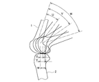
- the lower part of the femur 1 protrudes rearward, and is shaped like a combination of arcs of different sizes.
- the upper surface of the tibia 2 is substantially flat, and the knee is flexed and extended by sliding while the lower part of the femur 1 slides.
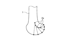
- FIG. 8 shows a locus drawn by the rotation center 2a at the lower part of the femur 1 along with the bending and extension movement of the knee.
- the rotation center 2a at the lower part of the femur 1 draws a locus of a curve while being shifted.
- the knee joint performs not a simple rotational movement but a sliding rolling movement.
- FIG. 7 shows an example of the relationship between the angle of the knee joint and the slip amount.
- the bending angles U, V, W of the knee joints correspond to the slip amounts u, v, w, respectively.
- the range of movement of the knee joint 1 for bending and stretching is about 0 ° to 130 ° when the knee is in an extended state at 0 °, and the range of movement used during walking is about 0 ° to 60 °. . In this range of motion, approximately 1 axis of rolling movement is performed between 10 ° and 15 ° from the beginning of bending of the knee, and then it gradually shifts to sliding movement to become sliding rolling movement.
- the knee joint movement assisting device disclosed in Patent Document 2 includes a connecting portion capable of moving a pivot (rotation center), and a driving portion provided with a cam mechanism performing a sliding motion between knee joint ends, and has a predetermined angle.
- the sliding movement is made between the knee joint ends while appropriately controlling the movement of the pivot.
- Patent No. 4092322 Patent No. 5713388 gazette
- the walking assistance device is manufactured and sold as a pair of left and right walking assistance units, and it is necessary for the purchase side to purchase both left and right walking assistance units even if only one walking assistance unit is necessary .
- the joint assistance unit provided in the walking assistance unit is used for both right and left, it has versatility and cost reduction can be easily achieved.
- the present invention has been made by taking the above problem as an example of the problem, and it is an object of the present invention to provide a joint assisting unit or the like which can be used by being shared with right and left joints.
- the present invention adopts the following composition.
- reference numerals in the drawings are attached in parentheses, but the present invention is not limited thereto.
- the joint assistance unit (20) comprises a first link (21) attached to one end of a knee joint and a second link attached to the other end of the knee joint ( 22) and a drive unit (30) for causing a relative rotational motion and a sliding motion while moving a rotational motion or a rotational center between the first link and the second link
- the drive The portion includes a peripheral cam (32), a driver (33) moving the peripheral edge of the peripheral cam, a first cam groove (41) formed inside the peripheral cam, and the first cam groove A second cam groove (45) disposed on the inner side of and asymmetrically formed with the first cam groove, a first cam pin (42) engaged with the first cam groove, and the second A second cam pin (46) engaged with the cam groove, and the movement of the drive body More, wherein the moving while engaged with at least said first cam pin and said second cam pin first or second cam groove.
- a joint assistance unit is the joint assistance unit according to claim 1, wherein the first cam groove and the second cam groove are the first link and the second link.
- the first and second cam pins are movable in correspondence with different driving directions generated between the first link and the second link with respect to the extension state.
- the joint assistance unit according to claim 3 is the joint assistance unit according to claim 1 or 2, wherein the first link and the second link are in the extended state, and the center of rotation and the two respective cam pins are provided. And an inner angle ( ⁇ ) at which each vertical line passing through each of the cam pins intersects with a straight line connecting at least 30 ° or more.
- a joint assistance unit is the joint assistance unit according to any one of the first to third aspects, wherein the first link and the second link are based on the extension state. The bending directions of the first link and the second link are switched according to the moving direction of the driving body.
- the walking assistance device (S) comprises an upper thigh attachment unit (5) mounted from the knee joint to the upper thigh (16) of the leg, and the knee joint to the lower thigh (17).
- the drive unit includes a peripheral cam, a driver for moving the peripheral edge of the peripheral cam, a first cam groove formed inside the peripheral cam, and an inner side of the first cam groove.
- first cam arranged in A second cam groove asymmetrically formed, a first cam pin engaged with the first cam groove, and a second cam pin engaged with the second cam groove, the drive According to the movement of the body, at least the first cam pin or the second cam pin is moved while being engaged with the first or second cam groove.
- FIG. 1 shows the use condition of a walk assistance apparatus
- FIG. 1 (a) shows the state which extended the leg
- FIG.1 (b) shows the state which bent the leg.
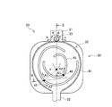
- FIG. 1 shows the structure of the joint assistance unit of a walk assistance apparatus.
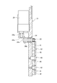
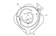
- FIG. II-II cross section of FIG. It is a schematic diagram which shows the operation example of the joint assistance unit which shows the state which the knee joint extended.
- It is explanatory drawing which shows a mode that the rotation center of the lower part of a femur moves with the bending of a knee joint.
- a walking assistance apparatus using a joint assistance unit for a knee joint of a user will be described.
- the “bending motion” refers to a motion for bending the knee joint
- the “extension motion” refers to a motion for extending the knee joint.
- the walking assistance device S of the present embodiment is attached to the leg of the user, and includes a walking assistance unit U that can be attached to both the left and right legs.
- the walking assistance unit U is attached to the knee joint, the upper thigh attachment unit 5 attached to the knee joint to the upper thigh 16 of the leg, the lower thigh attachment unit 10 attached to the knee joint to the lower thigh 17 and the knee joint And a joint assisting unit 20.
- the walking assistance device S is connected to, for example, the waist attachment unit 2 attached to the waist of the user, and when assistance is required for both legs, the walking assistance unit U is used for each of the left and right legs. It is attached.
- the walking assistance unit U is configured, for example, as shown in FIG. 1 (a), by swinging the lower thigh attachment unit 10 in the front-rear direction with respect to the upper thigh attachment unit 5 by driving a motor as a power source.
- the walking assistance is performed by appropriately performing the extension operation shown in 2.) and the bending operation shown in FIG.
- the waist attachment unit 2 includes a waist belt 3 which is wound around and attached to the user's waist, and a connector 4 connected to the upper thigh attachment unit 5 is provided on the left and right of the waist belt 3.
- the upper thigh attachment unit 5 has a flat upper thigh plate 6 disposed on the side of the upper thigh 16 of the user, and the upper end thereof is rotatably connected to the waist attachment unit 2 via the connector 7
- the upper thigh plate 6 is mounted to stand up along the outer side of the upper thigh 16. Further, the upper thigh plate 6 is provided with a contact member to be in contact with a part of the upper thigh portion 16 and a fixture 8 such as a surface fastener for closely contacting the contact member to the upper thigh portion 16.
- the upper thigh plate 6 is fixedly mounted on the knee by the.
- the lower leg mounting unit 10 also has a flat lower leg plate 11 disposed on the side of the lower leg 17 of the user, and the upper end portion of the lower leg mounting plate 10 has the joint assisting unit 20 between the upper leg portion 6 and the upper leg.
- the lower leg plate 11 is attached by hanging down along the outer surface of the lower leg 17.
- the lower leg plate 11 is provided with an attachment 12 such as a surface fastener for contacting under the knee and a contact member for contacting the ankle and the contact member to the under knee and the ankle.
- the lower end of the thigh plate 11 is fixedly attached to the lower knee and the ankle.
- the joint assisting unit 20 is disposed on the side of the knee joint of the user, and is provided with a flat first link 21 connected to the upper thigh plate 6 and the first link 21.
- a flat plate-like second link 22 which is connected to the link 21 in a flexible and extensible manner and is attached to the lower leg plate 11, and a rotational movement or center of rotation between the first link 21 and the second link 22
- a drive unit 30 for relatively rotating movement while moving X and for sliding movement in the front-rear direction.
- the driving unit 30 includes a peripheral cam 32, a driving body 33 moving the peripheral edge of the peripheral cam 32 by rotational driving, a first cam groove 41 formed inside the peripheral cam 32, and a first cam groove 41.
- a second cam groove 45 disposed inside and formed asymmetrically with the first cam groove 41, a first cam pin 42 engaged with the first cam groove 41, and an engagement with the second cam groove 45 And a second cam pin 46.
- the drive unit 30 is covered by a cover 24, which is attachable to and detachable from the first and second links 21, 22.
- a row of teeth engaged with the drive body 33 is formed on the peripheral edge of the peripheral edge cam 32, a row of teeth is also formed on the outer peripheral edge of the drive body 33, and the drive body 33 is a peripheral edge cam
- the peripheral cam 32 swings as the peripheral edge 32 moves along the dentition.
- the contour of the peripheral edge of the peripheral edge cam 32 is formed in an arc shape having a predetermined curvature formed according to the movement of the rotation center X, and the contours of the first and second cam grooves 41 and 45 are as shown in FIG.
- the rotational movement or sliding rolling movement of the knee joint as a movement trajectory of the knee joint shown in FIG. That is, as shown in FIGS. 7 and 8, the actual knee joint performs a simple rotational movement without slippage between 0 ° where the knee joint angle is straight and 15 ° when it begins to bend.
- contours of the first and second cam grooves 41 and 45 a portion corresponding to 0 ° to 15 ° of the knee joint angle is formed in a perfect circular arc, and when the knee joint angle is between 15 ° and 105 ° Since the knee joint performs rotational sliding motion, the contours of the first and second cam grooves 41 and 45 are formed in an elliptical arc, and the knee joint performs rotational motion again when the knee joint angle is 105 ° or more Thus, the contours of the first and second cam grooves 41 and 45 are formed in a perfect circular arc. As a result, in the upper thigh attachment unit 5 and the lower thigh attachment unit 10, movement similar to the movement of the actual knee joint is realized.
- the contours of the first and second cam grooves 41 and 45 are formed in the same manner as described above in response to the movement of the knee joint in the reverse direction.
- the first cam groove 41 and the second cam groove 45 are generated between the first link 21 and the second link 22 based on the first link 21 and the second link 22 in the extended state. Since the first cam pin 42 and the second cam pin 46 are formed movably corresponding to different drive directions, and the left and right legs can be driven, the joint auxiliary unit 20 can be used for both right and left legs. It is possible to use it.
- the shapes of the peripheral edge cam 32 and the cam grooves 41 and 45 are appropriately changed according to the size of the first and second links 21 and 22 and the arrangement position of the cam pins 42 and 46.
- the movement of the knee joint differs depending on the body type, age, sex and the like, but in this case as well, the shapes of the peripheral cam 32 and the cam grooves 41 and 45 may be changed.
- each of the driving body 33, the first cam pin 42 and the second cam pin 46 it is necessary to have resistance to each other, so that each of the driving body 33, the first cam pin 42 and the second cam pin 46 always It is arranged to be held as a vertex forming a predetermined triangle.
- each of the cam pins 42 and 46 disposed in each of the cam grooves 41 and 45 has the center of rotation X and the two cam pins in the extended state of the first link 21 and the second link 22. It is arranged such that the inner angle ( ⁇ ) at which the straight line connecting 42 and 46 perpendicularly intersects and the vertical line passing through the cam pins 42 and 46 intersects at least 30 ° ( ⁇ / 6 rad) or more.
- the upper limit value of this angle ( ⁇ ) is preferably 150 ° (5 / 6 ⁇ rad) or less in order to operate satisfactorily, but the range of this angle ( ⁇ ) is appropriately determined according to the bending range of the knee joint Be changed.
- the drive body 33 and the first and second cam pins 42, 46 are each cam pin according to the movement direction of the drive body 33 based on the time when the first link 21 and the second link 22 are in the extended state.
- the directions of movement of the first and second links 21 and 22 and the directions of movement of the first and second links 21 and 22 are switched.
- the cam pins 42 and 46 are cam grooves 41 and 45 by moving the drive body 33 in the a direction.
- the cam pins 42 and 46 can move the cam grooves 41 and 45 in the direction of arrow A2 in the figure by moving the driving body 33 in the direction b.
- the movement of the cam pins 42 and 46 switches the direction of the bending operation of the first link 21 and the second link 22.
- the bending direction of the knee joint can be easily changed by switching the moving direction of the driving body 33. Therefore, the joint can be mounted on the left and right legs, and the cost can be reduced. .
- each cam pin 42, 46 is engaged with each cam groove 41, 45.
- the first link 21 and the second link 22 perform relative rotational motion while moving the rotational motion or the rotation center X between the first link 21 and the second link 22.
- the sliding motion will be performed in the front and back direction.
- the movement of the first link 21 and the second link 22 at this time is similar to the rotational movement or sliding rolling movement of the knee joint shown in FIG. 7, and the rotation center 2a at the lower part of the femur 1 is shown in FIG. It moves so as to draw the locus of the curve shown in 8.
- the driving unit 30 uses a cam mechanism different from a cam mechanism for moving a cam pin in accordance with the movement trajectory of the rotation center X as in the conventional knee joint movement assisting device shown in Patent Document 2 It is possible to make a relative rotational movement while moving a rotational movement or a rotation center X between the second link 22 and the second link 22 and slide movement in the front-rear direction, and further, from the reference position, the cam pins 42, 46 Can be switched as the direction of the bending operation of the first link 21 and the second link 22 can be switched, so that it can function as the left and right combined walking assistance unit U.
- first link 21 and the second link 22 are arranged in an overlapping manner, and a motor 29 as a power source of the drive unit 30 is vertically attached to the first link 21. .
- the driving body 33 is disposed on the outer peripheral edge of the peripheral cam 32, rotatably pivoted on the first link 21, protrudes toward the second link 22, and engages with the teeth of the peripheral cam 32.
- the cam pins 42, 46 are attached to the first link 21 as rotatable rollers, project toward the second link 22 and engage with the cam grooves 41, 45.
- the driving body 33 is formed as a pinion, and its shaft 33 a is rotatably supported by the first link 21 via a bearing 34.
- a power transmission system from the motor 29 to the drive body 33 is also attached to the first link 21.
- the power transmission system is constituted by, for example, a gear train composed of a combination of a spur gear and a straight bevel gear, and a part of the gear train is provided as a gear reduction gear (not shown) in the motor 29.
- This gear reducer is constituted by, for example, a spur gear train.
- the shaft 29a of the end gear of the gear reducer projects downward substantially vertically from the casing of the motor 29, and a straight bevel gear 28a is fixed to the tip of the shaft 29a.
- Another straight bevel gear 28 b is engaged with the straight bevel gear 28 a, and the straight bevel gear 28 b is fixed to the shaft 33 a of the drive body 33.
- the motor 29 rotates, its power is transmitted to the driver 33, and the relative rotational movement and the sliding movement as described above occur between the first link 21 and the second link 22.
- the power transmission system is configured by the gear train including one or both of the spur gear and the straight bevel gear as described above, the movement is limited with respect to the input from the human body side without providing a clutch or the like. I have not. Therefore, self-locking is avoided, and patients can freely move their legs when motor 29 is not operating, as well as when patients etc. fall when motor 29 is operating. Even the leg can be moved so as to resist the motor 29 and it is stiff and safe.
- the motor 29 is controlled by a control unit (not shown) and rotates forward or reverse within a predetermined angular range of the peripheral cam 32.
- the driving body 33 rotates in the direction of arrow A, it revolves around the peripheral cam 32 in the direction of arrow a.
- the first link 21 and the second link 22 perform rotational movement at a rotational movement or different rotational centers according to a predetermined rotational angle, and slide and bend, for example, the upper thigh 16 of the patient It becomes possible to sit on a chair etc.
- the cam pins 42 and 46 move in the A1 direction, respectively.
- the link 21 and the second link 22 perform only rotational movement about the rotation center X without sliding movement. This corresponds to 0 ° -15 ° of the knee joint angle, within which the knee joint performs a simple rotational movement without slippage.
- the motor 29 is rotated in the reverse direction by the command from the control unit (not shown), and the drive body 33 is controlled to apply the driving force in the reverse direction of the arrow A, thereby the knee joint
- the patient's own weight bends by about 90 ° while being supported.
- the motor 29 is reversely rotated by a command from the control unit (not shown), and the driving body 33 rotates in the direction of the arrow B, as shown in FIG. 6, FIG. 5 and FIG. Revolve in the direction of This allows the patient to stand up from the seated state.
- the walking assistance unit U of the walking assistance device S is mounted on a leg of a patient or the like who has undergone knee replacement due to deterioration of knee osteoarthritis.
- the joint assistance unit 20 of the walking assistance unit U is applied to the outer surface of the knee joint of the patient
- the upper thigh attachment unit 5 is applied to the side surface of the upper thigh
- the lower thigh attachment unit 10 is the side of the lower thigh 17. Hit on.
- the connector 7 of the upper thigh attachment unit 5 is connected to the connector 4 of the waist belt 3 wound around the patient's waist, the attachment 8 is attached to the upper knee portion of the upper thigh 16, and the attachment 12 is It is attached to the lower knee and the ankle of the lower leg 17.
- a battery is attached to the waist belt 3, and a motor 29 is electrically connected to the battery.
- the motor 29 is controlled by a control unit (not shown) in various control modes such as walking and sitting.
- the driver 33 When the control mode for walking is set, the driver 33 starts to rotate in the direction of arrow A with the knee joint extended as shown in FIG. 4, and revolves around the peripheral cam 32 in the direction of arrow a.
- the upper thigh attachment unit 5 and the lower thigh attachment unit 10 perform a relative rotational movement to bend the knee joint as shown in FIG.
- the rotation angle of the knee joint by this rotation movement is, for example, in the range of 0 ° to 15 °.
- the upper thigh attachment unit 5 and the lower thigh attachment unit 10 perform a rotational motion while performing a relative sliding motion while the rotation center X moves obliquely upward to the left.
- the knee joint is flexed as shown in FIG.
- the rotation angle of the knee joint by this rotation sliding motion is, for example, in the range of 15 ° to 60 °.
- the upper thigh attachment unit 5 and the lower thigh attachment unit 10 perform the rotational motion while performing a relative sliding motion while the center of rotation X moves obliquely upward to the left.
- the mounting unit 10 moves in a manner similar to the sliding and rolling movement of the knee joint of the human body shown in FIG. 7, and the patient can naturally bend the leg naturally.
- the upper thigh attachment unit 5 and the lower thigh attachment unit 10 perform rotational motion while performing a relative sliding motion while the rotation center X moves obliquely downward.
- the movement approximates to the sliding and rolling movement of the knee joint of the human body shown in FIG. 7, and the patient can extend the leg naturally without unreasonableness.
- the driving body 33 starts to rotate in the direction of the arrow A in the state where the knee joint shown in FIG.
- the upper leg mounting unit 5 and the lower leg mounting unit 10 perform relative rotational movement or rotational sliding movement, and bend the knee joint through the states of FIGS. 5 and 6, as a result.
- the rotation angle of the knee joint by this rotation movement is, for example, in the range of 0 ° to 90 °.
- the driver 33 revolves the peripheral cam 32 by a predetermined angle in the direction of arrow a until the patient is seated, and then reverses the driving force in the direction of arrow b by reversing the peripheral cam 32 in the direction of arrow b.
- the knee joint flexion is supported, and then the motor 29 is stopped when the knee joint is in a flexed state of 90 ° due to the patient's own weight, and the upper thigh wearing unit 5 and the lower thigh wearing unit 10
- the relative rotational movement with it also stops, and the patient can sit on a chair or the like.
- the present invention is not limited to the above embodiment, and various modifications can be made within the scope of the present invention.
- the driving body 33 and the peripheral edge of the peripheral edge cam 32 are configured to mesh with each other by a dentition, the present invention is not particularly limited to this configuration.
- the motor was used as a drive source, it is also possible to use another type of drive source.
- S walking assistance device 20: joint assisting unit 21: first link 22: second link 30: driving portion 32: peripheral edge cam 33: driving body 41, 45: cam groove 42, 46: cam pin
Landscapes
- Health & Medical Sciences (AREA)
- Epidemiology (AREA)
- Pain & Pain Management (AREA)
- Physical Education & Sports Medicine (AREA)
- Rehabilitation Therapy (AREA)
- Life Sciences & Earth Sciences (AREA)
- Animal Behavior & Ethology (AREA)
- General Health & Medical Sciences (AREA)
- Public Health (AREA)
- Veterinary Medicine (AREA)
- Orthopedic Medicine & Surgery (AREA)
- Rehabilitation Tools (AREA)
Abstract
左右の関節に兼用して装着可能な関節補助ユニット等を提供する。 関節補助ユニット20は、膝関節の一端側に装着される第1のリンク21と、膝関節の他端側に装着される第2のリンク22と、第1のリンク21と第2のリンク22の間で回転運動ないし回転中心を移動させつつ相対的に回転運動させるとともにスライド運動させる駆動部30と、を具備する。
Description
本発明は、利用者の関節の動きを補助する関節補助ユニット等に関する。
変形性膝関節症の症状が悪化し、人工膝関節置換患者等における歩行運動、屈伸動作、リハビリテーション等の補助に使用される歩行補助装置が従来から知られている。この種の歩行補助装置は、複数存在し(例えば、特許文献1参照)、特許文献1に示す歩行補助装置は、ユーザの膝関節に装着され、アクチュエータを用いて膝関節回りを前後方向に揺動させる脚リンクを備えた関節補助ユニットを具備している。
ところで、人体の膝関節は大腿骨、脛骨、膝蓋骨からなる骨の部分と、半月板からなる軟骨と、前十字靭帯、後十字靭帯、内側副靭帯、外側副靭帯等の靭帯によって構成される。
図7に示すように、大腿骨1の下部は後方に突出しており、いくつもの大きさの違う円弧を組み合わせたような形状になっている。脛骨2の上面は略平坦でこの上を大腿骨1の下部が滑りながら回転することで膝の屈伸運動が行われる。
図8は膝の屈伸運動に伴って大腿骨1の下部の回転中心2aが描く軌跡を示す。図8から明らかなように、膝関節が屈伸すると大腿骨1の下部の回転中心2aは、ずれながら曲線の軌跡を描く。このように膝関節は単なる回転運動を行うのではなく、すべり転がり運動を行っている。
また、図7は膝関節の角度とすべり量との関係の一例を示す。図7中、膝関節の屈曲角度U,V,Wはすべり量u,v,wにそれぞれ対応する。膝関節1の屈伸運動の可動域は、膝が伸びた状態のときを0°とすると、0°~130°程度であり、歩行時に使用している可動域は大体0°~60°である。この可動域のうち、膝の曲がり始めから10°~15°の間は、略一軸の転がり運動をし、その後徐々にすべり運動へ移行してすべり転がり運動となる。
従来、このような膝関節のすべり転がり運動を考慮して、人体の上腿部に装着される上腿装着部に対して人体の下腿部に装着される下腿装着部を回転させたときに、下腿装着部の膝関節側端部が前後方向にスライドするようにした膝関節運動補助装置が提案されている(例えば、特許文献2参照。)。この膝関節運動補助装置によれば、人間の膝関節運動への追従性を高めることができ、装具のずれを防止したり、装着違和感等を解決したりすることができる。
特許文献2に示す膝関節運動補助装置は、枢軸(回転中心)を移動可能な連結部と、膝関節端部間がスライド運動を行うカム機構を備えた駆動部と、を備え、所定の角度において、枢軸を適宜移動制御しつつ膝関節端部間をスライド運動させる。
このような膝関節運動補助装置は、左右の脚に装着した際に駆動方向が異なるため、左右別々に専用の装置を製造する必要があり、コストが高騰する要因となっていた。
また、特許文献2に示す膝関節運動補助装置を改良することで左右兼用の装置を製造可能であるか否かについて検討したものの、連結部を用いることなく所定の動作を行う構成とする必要性が生じた。
また、通常、歩行補助装置は左右の歩行補助ユニットを一対として製造販売され、購入する側は、片側の歩行補助ユニットのみが必要であっても左右両方の歩行補助ユニットを購入する必要があった。
一方で、歩行補助ユニットに設けられている関節補助ユニットが左右兼用であれば、汎用性があってコストダウンを容易に図ることができる。
そこで、本発明は上記問題を課題の一例として為されたもので、左右の関節に兼用して装着可能な関節補助ユニット等を提供することを目的とする。
上記課題を解決するため、本発明は次のような構成を採用する。なお、本発明の理解を容易にするため図面の参照符号を括弧書きで付するが、本発明はこれに限定されるものではない。
すなわち、請求項1に記載の関節補助ユニット(20)は、膝関節の一端側に装着される第1のリンク(21)と、前記膝関節の他端側に装着される第2のリンク(22)と、前記第1のリンクと前記第2のリンクの間で回転運動ないし回転中心を移動させつつ相対的に回転運動させるとともにスライド運動させる駆動部(30)と、を具備し、前記駆動部は、周縁カム(32)と、前記周縁カムの周縁を移動する駆動体(33)と、前記周縁カムの内側に形成される第1のカム溝(41)と、前記第1のカム溝の内側に配置され前記第1のカム溝と非対称に形成される第2のカム溝(45)と、前記第1のカム溝と係合する第1のカムピン(42)と、前記第2のカム溝と係合する第2のカムピン(46)と、を備え、前記駆動体の移動により、少なくとも前記第1のカムピン又は第2のカムピンを前記第1又は第2のカム溝と係合させつつ移動させることを特徴とする。
また、請求項2に記載の関節補助ユニットは、請求項1に記載の関節補助ユニットにおいて、前記第1のカム溝と前記第2のカム溝は、前記第1のリンクと前記第2のリンクが伸展状態を基準として、前記第1のリンクと前記第2のリンクの間に生じる異なる駆動方向に対応して前記第1及び第2のカムピンが移動可能であることを特徴とする。
また、請求項3に記載の関節補助ユニットは、請求項1又は2に記載の関節補助ユニットにおいて、前記第1のリンクと前記第2のリンクが伸展状態において、回転中心と2つの各前記カムピンとを結ぶ直線と垂直に交わり各前記カムピンを通るそれぞれの垂線が交わる内側の角度(α)が少なくとも30°以上であることを特徴とする。
また、請求項4に記載の関節補助ユニットは、請求項1乃至3のいずれか一項に記載の関節補助ユニットにおいて、前記第1のリンクと前記第2のリンクが伸展状態を基準として、前記駆動体の移動方向に応じて、前記第1のリンクと前記第2のリンクの屈曲方向が切り替わることを特徴とする。
また、請求項5に記載の歩行補助装置(S)は、脚の膝関節から上腿部(16)にかけて装着される上腿装着ユニット(5)と、前記膝関節から下腿部(17)にかけて装着される下腿装着ユニット(10)と、前記膝関節に装着される関節補助ユニット(20)と、を備え、前記関節補助ユニットは、前記上腿装着ユニットと連結される第1のリンクと、前記下腿装着ユニットに装着される第2のリンクと、前記第1のリンクと前記第2のリンクの間で回転運動ないし回転中心を移動させつつ相対的に回転運動させるとともにスライド運動させる駆動部と、を具備し、前記駆動部は、周縁カムと、前記周縁カムの周縁を移動する駆動体と、周縁カムの内側に形成される第1のカム溝と、前記第1のカム溝の内側に配置され前記第1のカム溝と非対称に形成される第2のカム溝と、前記第1のカム溝と係合する第1のカムピンと、前記第2のカム溝と係合する第2のカムピンと、を備え、前記駆動体の移動により、少なくとも前記第1のカムピン又は第2のカムピンを前記第1又は第2のカム溝と係合させつつ移動させることを特徴とする。
実際の膝関節の動きに近似した動きを実現することができる。また、屈曲方向を切替えることができるので左右の脚に兼用して装着することができる。
以下、図面を参照して本発明の実施の形態について説明する。なお、以下の説明において、関節補助ユニットを、利用者の膝関節に用いた歩行補助装置について説明を行う。また、以下の説明において、「屈曲動作」とは、膝関節を曲げる動作をいい、「伸展動作」とは、膝関節が伸びる動作をいう。
図1に示すように、本実施形態の歩行補助装置Sは、利用者の脚に装着されるもので、左右の脚に兼用して装着可能な歩行補助ユニットUを備えている。この歩行補助ユニットUは、脚の膝関節から上腿部16にかけて装着される上腿装着ユニット5と、膝関節から下腿部17にかけて装着される下腿装着ユニット10と、膝関節に装着される関節補助ユニット20と、を備えている。なお、歩行補助装置Sは、例えば、利用者の腰部に装着される腰部装着ユニット2に連結されて用いられ、両脚に補助が必要な場合には、歩行補助ユニットUが左右のそれぞれの脚に装着される。
この歩行補助ユニットUは、動力源としての例えばモーターの駆動により上腿装着ユニット5に対して下腿装着ユニット10を前後方向に揺動させることで、使用者に対して、例えば、図1(a)に示す伸展動作と、図1(b)に示す屈曲動作を適正に行わせ、歩行補助を行う。
腰部装着ユニット2は、利用者の腰に巻回して取り付けられる腰ベルト3を備え、腰ベルト3の左右には、上腿装着ユニット5と連結される連結具4が設けられている。
上腿装着ユニット5は、利用者の上腿部16の側面に配置される平板状の上腿部プレート6を有し、上端部が腰部装着ユニット2に連結具7を介して回転可能に連結され、上腿部プレート6は上腿部16の外側面に沿って立ち上がるようにして取り付けられる。また、上腿部プレート6には、上腿部16の一部に接触させる接触部材や接触部材を上腿部16に密着させる面ファスナ等の取付具8が設けられており、この取付具8によって上腿部プレート6が膝上に固定して取り付けられる。
また、下腿装着ユニット10は、利用者の下腿部17の側面に配置される平板状の下腿部プレート11を有し、上端部が上腿部プレート6との間で関節補助ユニット20を介して連結され、下腿部プレート11は下腿部17の外側面に沿って垂下して取り付けられる。また、下腿部プレート11には、膝下に接触、及び足首に接触させる接触部材や接触部材を膝下及び足首に密着させる面ファスナ等の取付具12が設けられており、この取付具12によって下腿部プレート11の下端部が膝下及び足首に固定して取り付けられる。
図1及び図2に示すように、関節補助ユニット20は、利用者の膝関節の側面に配置され、上腿部プレート6に連結される平板状の第1のリンク21と、この第1のリンク21との間で屈伸自在に連結され、下腿部プレート11に取り付けられる平板状の第2のリンク22と、第1のリンク21と第2のリンク22との間で回転運動ないし回転中心Xを移動させつつ相対的に回転運動させるとともに前後方向にスライド運動させる駆動部30と、を備えている。
駆動部30は、周縁カム32と、回転駆動によって周縁カム32の周縁を移動する駆動体33と、周縁カム32の内側に形成される第1のカム溝41と、第1のカム溝41の内側に配置され第1のカム溝41と非対称に形成される第2のカム溝45と、第1のカム溝41と係合する第1のカムピン42と、第2のカム溝45と係合する第2のカムピン46と、を備えている。駆動部30はカバー24によって覆われ、カバー24は第1及び第2のリンク21、22に対して着脱可能である。
周縁カム32の周縁には、例えば、駆動体33が係合する歯列が形成され、駆動体33の外周縁にも歯列が形成され、駆動体33の回転により、駆動体33が周縁カム32の周縁を歯列に沿って移動すると同時に周縁カム32が揺動する。
また、周縁カム32の周縁の輪郭は、回転中心Xの動きに応じて形成される所定の曲率を有する円弧状に形成され、第1及び第2のカム溝41、45の輪郭は、図7及び図8に示す膝関節の移動軌跡としての膝関節の回転運動ないしすべり転がり運動を生じるように形成される。すなわち、実際の膝関節は、図7及び図8に示したように、膝関節角がまっすぐな0°から曲がり始めの15°の間は、すべりのない単純な回転運動を行うことから、第1及び第2のカム溝41、45の輪郭のうち膝関節角の0°~15°に対応する部分は、真円状の円弧に形成され、膝関節角が15°~105°の間では、膝関節は回転すべり運動を行うことから、第1及び第2のカム溝41、45の輪郭は楕円状の円弧に形成され、膝関節角が105°以上では膝関節は再び回転運動を行うことから、第1及び第2のカム溝41、45の輪郭は真円状の円弧に形成される。これにより、上腿装着ユニット5と下腿装着ユニット10には、実際の膝関節の動きに近似した動きが実現される。
なお、第1及び第2のカム溝41、45の輪郭は、膝関節の逆方向の動作にも対応して上記同様に形成される。
そして、第1のカム溝41と第2のカム溝45は、第1のリンク21と第2のリンク22が伸展状態を基準として、第1のリンク21と第2のリンク22の間に生じる異なる駆動方向に対応して第1のカムピン42及び第2のカムピン46が移動可能に形成され、左右の脚の駆動動作を行うことが可能であるから、関節補助ユニット20を左右の脚に兼用して用いることが可能である。
なお、周縁カム32やカム溝41、45の形状は、第1及び第2のリンク21、22の大きさやカムピン42、46の配置位置によって適宜変更される。また、膝関節の動きは、体型、年齢、性別等によって違いが生じるが、この場合にも周縁カム32やカム溝41、45の形状を変えればよい。
また、第1のカムピン42、又は第2のカムピン46が移動する際には、互いに抵抗を有する必要があるため、常に、駆動体33と第1のカムピン42と第2のカムピン46の各々が所定の三角形を形成する頂点として保持されるように配置される。
また、図4に示すように、各カム溝41、45に配置される各カムピン42、46は、第1のリンク21と第2のリンク22が伸展状態において、回転中心Xと2つの各カムピン42、46とを結ぶ直線と垂直に交わり各カムピン42、46を通るそれぞれの垂線が交わる内側の角度(α)が少なくとも30°(π/6rad)以上となるように配置される。この角度(α)を30°以上にすることで、カムピン42、46同志の連れ回りや、カムピン42、46が移動する際にカム溝41、45に引っかかる等を防ぐことができる。なお、この角度(α)の上限値は、良好に動作させるために150°(5/6πrad)以下であることが好ましいが、この角度(α)の範囲は、膝関節の屈曲範囲にしたがって適宜変更される。
また、駆動体33と第1及び第2のカムピン42、46は、第1のリンク21と第2のリンク22が伸展状態の時を基準として、駆動体33の移動方向に応じて、各カムピン42、46の移動方向及び第1のリンク21と第2のリンク22の屈曲動作の方向が切替わるように配置されている。具体的には、図2に示すように、第1のリンク21と第2のリンク22が伸展状態において、駆動体33をa方向に移動することで、カムピン42、46はカム溝41、45を図中の矢印A1方向に移動可能となっており、駆動体33をb方向に移動することで、カムピン42、46はカム溝41、45を図中の矢印A2方向に移動可能である。また、このカムピン42、46の移動によって第1のリンク21と第2のリンク22の屈曲動作の方向が切り替わる。このようにすれば、駆動体33の移動方向を切替えることで、容易に膝関節の屈曲方向を変更することができるので、左右の脚に兼用して装着することができコストの低減化を図れる。
このように構成された駆動部30は、図4乃至図7に示すように、駆動体33が周縁カム32の周縁を移動することによって、各カムピン42、46が各カム溝41、45と係合しつつ移動し、第1のリンク21と第2のリンク22とが第1のリンク21と第2のリンク22の間で回転運動ないし回転中心Xを移動させつつ相対的な回転運動を行うと同時に、前後方向にスライド運動を行うこととなる。このときの第1のリンク21と第2のリンク22の動きは、図7に示した膝関節の回転運動ないしすべり転がり運動に近似し、また、大腿骨1の下部における回転中心2aは、図8に示した曲線の軌跡を描くように移動する。
また、駆動部30は、特許文献2に示す従来の膝関節運動補助装置のように回転中心Xの移動軌跡にしたがってカムピンを移動させるカム機構とは異なるカム機構を用いて、第1のリンク21と第2のリンク22との間で回転運動ないし回転中心Xを移動させつつ相対的に回転運動させるとともに前後方向にスライド運動させることが可能となっており、さらに、基準位置からカムピン42、46を互いに反対方向に移動することで第1のリンク21と第2のリンク22の屈曲動作の方向を切替えることができるため、左右兼用の歩行補助ユニットUとして機能させることができる。
また、図3に示すように、第1のリンク21と第2のリンク22は重ね合されて配置され、駆動部30の動力源としてのモーター29が第1のリンク21に縦向きに取り付けられる。
駆動体33は周縁カム32の外周縁に配置され、第1のリンク21に回転可能に枢支され、第2のリンク22側に突出し、周縁カム32の歯列に係合する。カムピン42、46は回転自在なローラとして第1のリンク21に取り付けられ、第2のリンク22側に突出し、カム溝41、45と係合する。駆動体33はピニオンとして形成され、その軸33aが第1のリンク21にベアリング34を介して回転自在に支持される。
また、このモーター29から上記駆動体33への動力伝達系もこの第1のリンク21に取り付けられる。動力伝達系は、例えば、平歯車及びすぐばかさ歯車の組合せからなる歯車列によって構成され、歯車列の一部はモーター29内の図示しない歯車減速機として設けられる。この歯車減速機は例えば平歯車列によって構成される。
歯車減速機の終端歯車の軸29aはモーター29のケーシングから略垂直下方に向かって突出し、その軸29aの先端にすぐばかさ歯車28aが固定される。このすぐばかさ歯車28aには他のすぐばかさ歯車28bが噛み合っており、このすぐばかさ歯車28bが上記駆動体33の軸33aに固定される。
これにより、モーター29が回転すると、その動力が駆動体33に伝達され、上述したような相対的回転運動及びスライド運動が第1のリンク21と第2のリンク22との間に生じることになる。また、このように動力伝達系が平歯車及びすぐばかさ歯車の一方又は双方からなる歯車列によって構成されることから、クラッチ等を設けずとも人体側からの入力に対してその動きを制限することがない。したがって、セルフロックが回避されることとなり、モーター29の非稼動時に患者等は自由に脚を動かせることができるのはもちろんのこと、モーター29の稼動時において患者等が転倒するような場合であってもモーター29に抗するように脚を動かせることができるのですこぶる安全である。
上記モーター29は図示しない制御部によって制御され、上記周縁カム32の所定の角度範囲内において正転し又は逆転する。
次に、本実施形態の関節補助ユニット20の動作例を図4乃至図6を用いて説明する。
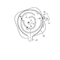
例えば、本実施形態の関節補助ユニット20を装着した利用者が、図4に示す起立状態から図5に示す中間状態を経て図6に示す屈曲状態に姿勢を変更しようとする場合は、図4に示すように、駆動体33が矢印Aの方向に回転しつつ周縁カム32の回りを矢印aの方向に公転する。これにより、第1のリンク21と第2のリンク22は、所定の回転角度に応じて回転運動ないし異なる回転中心で回転運動を行うとともにスライド運動して屈曲し、例えば患者の上腿部16は椅子等に着座可能になる。
図4に示すように、第1のリンク21が第2のリンク22に対して真っ直ぐに伸びた状態から少しばかり屈曲するまでは、各カムピン42、46はそれぞれA1方向に移動するものの、第1のリンク21と第2のリンク22は、スライド運動することなく回転中心Xを中心に回転運動のみ行う。これは、膝関節角の0°~15°に対応し、この角度範囲内では、膝関節はすべりのない単純な回転運動を行う。
次に、 図5及び図6に示すように、第1のリンク21が第2のリンク22に対して更に曲がろうとすると、実際の膝関節の移動時の回転中心の移動軌跡を示す仮想回転中心軌跡X1にしたがって回転中心Xが左斜め上方に移動しつつスライド運動を行いながら回転運動を行う。これは、膝関節角の15°~105°に対応する。これにより、図6に示す屈曲状態からさらに、第1のリンク21は第2のリンク22に対して約90°屈曲し、患者は無理なく椅子等に着座することができる。
なお、患者が着座する直前の状態においては、図示しない制御部からの指令によってモーター29が逆方向に回転し、駆動体33が矢印Aの逆方向に駆動力を加えるように制御されて膝関節の屈曲が支えられつつ、患者の自重によって約90°屈曲する。
その後、図示しない制御部からの指令によってモーター29が逆転し、図6、図5および図4で順次示すように、駆動体33が矢印Bの方向に回転しつつ周縁カム32の回りを矢印bの方向に公転する。これにより、患者は着座状態から起立することが可能になる。
なお、第1のリンク21と第2のリンク22が伸展状態において、駆動体33を矢印Bの方向に回転しつつ周縁カム32の回りを矢印b方向に公転した場合には、各カムピン42、46は逆方向に移動し、回転中心Xは右斜め上方に移動し、上記同様に動作する。
次に、本実施形態の歩行補助装置の作用について説明する。
まず、例えば、歩行補助装置Sの歩行補助ユニットUは、図1(a)に示すように、変形性膝関節症が悪化し、人工膝関節置換となった患者等の脚に装着される。
すなわち、歩行補助ユニットUの関節補助ユニット20が患者の膝関節の外側面に当てられ、上腿装着ユニット5が上腿部16の側面に当てられ、下腿装着ユニット10が下腿部17の側面に当てられる。
そして、上腿装着ユニット5の連結具7が患者の腰に巻き付けられた腰ベルト3の連結具4と連結され、取付具8が上腿部16の膝上部分に取り付けられ、取付具12が下腿部17の膝下部分及び足首に取り付けられる。
その他、図示しないが電池が腰ベルト3に取り付けられ、この電池にモーター29が電気的に接続される。
モーター29の図示しないON/OFFスイッチが入れられると、モーター29が起動し、その動力が駆動部30の歯車列を介して駆動体33に入力される。
モーター29は図示しない制御部によって歩行用、着座用等の各種の制御モードで制御される。
歩行用の制御モードにセットされた場合は、図4のごとく膝関節が伸展した状態で駆動体33が矢印Aの方向に回り始め、周縁カム32の回りを矢印a方向に公転し、その結果、上腿装着ユニット5と下腿装着ユニット10とが相対的回転運動を行って図5のごとく膝関節を屈曲させる。この回転運動による膝関節の回転角度は例えば0°~15°の範囲内である。
更に、駆動体33が矢印aの方向に移動すると、上腿装着ユニット5と下腿装着ユニット10とが、回転中心Xが左斜め上方に移動しつつ相対的にスライド運動を行いながら回転運動を行って、図6のごとく膝関節を屈曲させる。この回転すべり運動による膝関節の回転角度は、例えば、15°~60°の範囲内である。
このように、上腿装着ユニット5と下腿装着ユニット10とが、回転中心Xが左斜め上方に移動しつつ相対的にスライド運動を行いながら回転運動を行うことから、上腿装着ユニット5と下腿装着ユニット10は、図7に示した人体の膝関節のすべり転がり運動に近似した動きをすることとなり、患者は無理なく自然に脚を屈曲させることができる。
駆動体33が周縁カム32の回りを矢印a方向に所定角度だけ公転すると、モーター29が逆転に切り替えられ、駆動体33が矢印Bの方向に回り始め、周縁カム32の回りを矢印b方向に公転し、その結果、図6、図5、図4の順に上腿装着ユニット5と下腿装着ユニット10とが相対的に動作し、膝関節を伸展させる。
これにより、上腿装着ユニット5と下腿装着ユニット10とが、回転中心Xが斜め下方に移動しつつ相対的にスライド運動を行いながら回転運動を行うことから、上腿装着ユニット5と下腿装着ユニット10は、図7に示した人体の膝関節のすべり転がり運動に近似した動きをすることとなり、患者は無理なく自然に脚を伸ばすことができる。
その後、モーター29の正逆転の繰り返しによって、上記駆動体33の回転が矢印Aの方向と矢印Bの方向に交互に切り替えられ、上腿装着ユニット5と下腿装着ユニット10の伸展と屈曲とが繰り返され、図1(A)(B)に示すように、患者の歩行動作が補助される。
一方で、モーター29が図示しない制御部によって着座用の制御モードにセットされた場合は、図4に示す膝関節が伸展した状態で駆動体33が矢印Aの方向に回り始め、周縁カム32の回りを矢印a方向に公転し、その結果、上腿装着ユニット5と下腿装着ユニット10とが相対的回転運動又は回転すべり運動を行い、図5及び図6の状態を経て、膝関節を屈曲させる。この回転運動による膝関節の回転角度は例えば0°~90°の範囲内である。
なお、駆動体33は、患者が着座前の状態まで周縁カム32の回りを矢印a方向に所定角度だけ公転し、その後、周縁カム32の回りを矢印b方向に逆転して駆動力を逆方向に加えて、膝関節の屈曲を支え、その後、患者の自重によって膝関節の回転角度が90°の屈曲状態になった際に、モーター29を停止し、上腿装着ユニット5と下腿装着ユニット10との相対的回転運動も停止し、患者は椅子等に着座可能となる。
なお、本発明は、上記実施形態に限定されるものではなく、本発明の要旨の範囲内において種々の変更が可能である。例えば、駆動体33と周縁カム32の周縁は歯列によって噛み合うように構成されているが、特にその構成に限定されるものではない。また、駆動源としてモーターを用いたが他の種類の駆動源を使用することも可能である。
S…歩行補助装置
20…関節補助ユニット
21…第1のリンク
22…第2のリンク
30…駆動部
32…周縁カム
33…駆動体
41、45…カム溝
42、46…カムピン
20…関節補助ユニット
21…第1のリンク
22…第2のリンク
30…駆動部
32…周縁カム
33…駆動体
41、45…カム溝
42、46…カムピン
Claims (5)
- 膝関節の一端側に装着される第1のリンクと、
前記膝関節の他端側に装着される第2のリンクと、
前記第1のリンクと前記第2のリンクの間で回転運動ないし回転中心を移動させつつ相対的に回転運動させるとともにスライド運動させる駆動部と、を具備し、
前記駆動部は、
周縁カムと、
前記周縁カムの周縁を移動する駆動体と、
前記周縁カムの内側に形成される第1のカム溝と、前記第1のカム溝の内側に配置され前記第1のカム溝と非対称に形成される第2のカム溝と、
前記第1のカム溝と係合する第1のカムピンと、
前記第2のカム溝と係合する第2のカムピンと、
を備え、
前記駆動体の移動により、少なくとも前記第1のカムピン又は前記第2のカムピンを前記第1又は第2のカム溝と係合させつつ移動させることを特徴とする関節補助ユニット。 - 前記第1のカム溝と前記第2のカム溝は、前記第1のリンクと前記第2のリンクが伸展状態を基準として、前記第1のリンクと前記第2のリンクの間に生じる異なる駆動方向に対応して前記第1及び第2のカムピンが移動可能であることを特徴とする請求項1に記載の関節補助ユニット。
- 前記第1のリンクと前記第2のリンクが伸展状態において、前記回転中心と2つの各前記カムピンとを結ぶ直線と垂直に交わり各前記カムピンを通るそれぞれの垂線が交わる内側の角度が少なくとも30°以上であることを特徴とする請求項1又は2に記載の関節補助ユニット。
- 前記第1のリンクと前記第2のリンクが伸展状態を基準として、前記駆動体の移動方向に応じて、前記第1のリンクと前記第2のリンクの屈曲方向が切り替わることを特徴とする請求項1乃至3のいずれか一項に記載の関節補助ユニット。
- 脚の膝関節から上腿部にかけて装着される上腿装着ユニットと、前記膝関節から下腿部にかけて装着される下腿装着ユニットと、前記膝関節に装着される関節補助ユニットと、を備え、
前記関節補助ユニットは、
前記上腿装着ユニットと連結される第1のリンクと、
前記下腿装着ユニットに装着される第2のリンクと、
前記第1のリンクと前記第2のリンクの間で回転運動ないし回転中心を移動させつつ相対的に回転運動させるとともにスライド運動させる駆動部と、を具備し、
前記駆動部は、
周縁カムと、
前記周縁カムの周縁を移動する駆動体と、
前記周縁カムの内側に形成される第1のカム溝と、前記第1のカム溝の内側に配置され前記第1のカム溝と非対称に形成される第2のカム溝と、
前記第1のカム溝と係合する第1のカムピンと、
前記第2のカム溝と係合する第2のカムピンと、
を備え、
前記駆動体の移動により、少なくとも前記第1のカムピン又は前記第2のカムピンを前記第1又は第2のカム溝と係合させつつ移動させることを特徴とする歩行補助装置。
Priority Applications (3)
| Application Number | Priority Date | Filing Date | Title |
|---|---|---|---|
| CN201880083931.9A CN112074260B (zh) | 2017-12-25 | 2018-12-12 | 关节辅助单元、步行辅助装置 |
| EP18897685.6A EP3733146A4 (en) | 2017-12-25 | 2018-12-12 | ARTICULATION ASSISTANCE UNIT AND WALKING ASSISTANCE DEVICE |
| US16/957,452 US11357692B2 (en) | 2017-12-25 | 2018-12-12 | Joint support unit and walking support apparatus |
Applications Claiming Priority (2)
| Application Number | Priority Date | Filing Date | Title |
|---|---|---|---|
| JP2017-248375 | 2017-12-25 | ||
| JP2017248375A JP7016075B2 (ja) | 2017-12-25 | 2017-12-25 | 関節補助ユニット、歩行補助装置 |
Publications (1)
| Publication Number | Publication Date |
|---|---|
| WO2019131152A1 true WO2019131152A1 (ja) | 2019-07-04 |
Family
ID=67067210
Family Applications (1)
| Application Number | Title | Priority Date | Filing Date |
|---|---|---|---|
| PCT/JP2018/045759 Ceased WO2019131152A1 (ja) | 2017-12-25 | 2018-12-12 | 関節補助ユニット、歩行補助装置 |
Country Status (5)
| Country | Link |
|---|---|
| US (1) | US11357692B2 (ja) |
| EP (1) | EP3733146A4 (ja) |
| JP (1) | JP7016075B2 (ja) |
| CN (1) | CN112074260B (ja) |
| WO (1) | WO2019131152A1 (ja) |
Cited By (1)
| Publication number | Priority date | Publication date | Assignee | Title |
|---|---|---|---|---|
| EP3998053A4 (en) * | 2019-07-08 | 2023-11-08 | Beijing AI-Robotics Technology Co., Ltd. | CAM AND NON-CIRCULAR GEAR PAIR FOR A NON-DRIVEN MULTI-JOINT SYNCHRONOUS TRAINING APPARATUS, ITS MANUFACTURING METHOD, TRANSMISSION MECHANISM USING THE SAME AND NON-DRIVEN MULTI-JOINT SYNCHRONOUS TRAINING APPARATUS |
Families Citing this family (5)
| Publication number | Priority date | Publication date | Assignee | Title |
|---|---|---|---|---|
| USD947388S1 (en) * | 2018-12-10 | 2022-03-29 | Jtekt Corporation | Motion assisting device |
| JP7100003B2 (ja) * | 2019-09-13 | 2022-07-12 | 本田技研工業株式会社 | アシスト装置 |
| CN112842830B (zh) * | 2020-12-30 | 2023-03-10 | 江苏集萃微纳自动化系统与装备技术研究所有限公司 | 基于柔性凸轮系统的外骨骼膝关节驱动结构及方法 |
| JP7512922B2 (ja) * | 2021-02-15 | 2024-07-09 | トヨタ自動車株式会社 | 膝装具及び脚装具 |
| CN115844682A (zh) * | 2022-11-30 | 2023-03-28 | 浙江工业大学 | 一种线驱动仿生人体肘关节外骨骼 |
Citations (5)
| Publication number | Priority date | Publication date | Assignee | Title |
|---|---|---|---|---|
| JPS5713388B2 (ja) | 1979-06-05 | 1982-03-17 | ||
| JP4092322B2 (ja) | 2004-10-20 | 2008-05-28 | 本田技研工業株式会社 | 歩行補助装置 |
| JP2012165823A (ja) * | 2011-02-10 | 2012-09-06 | Univ Of Yamanashi | 膝関節運動補助装置 |
| WO2015123451A1 (en) * | 2014-02-12 | 2015-08-20 | University Of South Florida | Systems and methods for designing kinetic shapes |
| JP2016059763A (ja) * | 2014-09-22 | 2016-04-25 | 国立大学法人山梨大学 | 下肢動作支援装置 |
Family Cites Families (13)
| Publication number | Priority date | Publication date | Assignee | Title |
|---|---|---|---|---|
| US3779654A (en) * | 1971-08-06 | 1973-12-18 | R Horne | Artificial joint |
| SE512505C2 (sv) * | 1997-04-01 | 2000-03-27 | Camp Scandinavia Ab | Knäortos mot hyperextension |
| US6824569B2 (en) * | 2002-10-11 | 2004-11-30 | Adeola Okediji | Reciprocal gait orthotic and prosthetic device |
| DE202006005095U1 (de) * | 2006-03-28 | 2006-06-01 | Aequos Endoprothetik Gmbh | Exoprothese oder Orthese zur Stabilisierung des menschlichen Kniegelenkes |
| KR101040631B1 (ko) * | 2006-06-29 | 2011-06-10 | 혼다 기켄 고교 가부시키가이샤 | 보행 보조 장치 |
| CN103260576B (zh) * | 2010-12-16 | 2015-04-22 | 丰田自动车株式会社 | 行走辅助装置 |
| CN104853712B (zh) * | 2012-12-14 | 2017-07-28 | 国立大学法人名古屋工业大学 | 行走辅助机 |
| KR102241853B1 (ko) * | 2014-03-28 | 2021-04-19 | 삼성전자주식회사 | 관절 어셈블리 및 이를 포함하는 보행보조로봇 |
| KR20180053293A (ko) * | 2015-06-23 | 2018-05-21 | 더 리전츠 오브 더 유니버시티 오브 캘리포니아 | 수동 절전형 인공 무릎 |
| DE112016004882B4 (de) * | 2015-10-26 | 2021-12-16 | U-Shin Ltd. | Türkantenschutzvorrichtung |
| ITUB20155017A1 (it) * | 2015-11-02 | 2017-05-02 | Luca Simone Poli | Esoscheletro e relativo procedimento di funzionamento |
| US10912666B2 (en) * | 2016-12-08 | 2021-02-09 | University Of Washington | Energy storage device for an exoskeleton |
| JP6845045B2 (ja) * | 2017-03-03 | 2021-03-17 | サンコール株式会社 | 長下肢装具用アクチュエータユニット |
-
2017
- 2017-12-25 JP JP2017248375A patent/JP7016075B2/ja active Active
-
2018
- 2018-12-12 EP EP18897685.6A patent/EP3733146A4/en not_active Withdrawn
- 2018-12-12 CN CN201880083931.9A patent/CN112074260B/zh active Active
- 2018-12-12 WO PCT/JP2018/045759 patent/WO2019131152A1/ja not_active Ceased
- 2018-12-12 US US16/957,452 patent/US11357692B2/en active Active
Patent Citations (5)
| Publication number | Priority date | Publication date | Assignee | Title |
|---|---|---|---|---|
| JPS5713388B2 (ja) | 1979-06-05 | 1982-03-17 | ||
| JP4092322B2 (ja) | 2004-10-20 | 2008-05-28 | 本田技研工業株式会社 | 歩行補助装置 |
| JP2012165823A (ja) * | 2011-02-10 | 2012-09-06 | Univ Of Yamanashi | 膝関節運動補助装置 |
| WO2015123451A1 (en) * | 2014-02-12 | 2015-08-20 | University Of South Florida | Systems and methods for designing kinetic shapes |
| JP2016059763A (ja) * | 2014-09-22 | 2016-04-25 | 国立大学法人山梨大学 | 下肢動作支援装置 |
Non-Patent Citations (1)
| Title |
|---|
| See also references of EP3733146A4 |
Cited By (2)
| Publication number | Priority date | Publication date | Assignee | Title |
|---|---|---|---|---|
| EP3998053A4 (en) * | 2019-07-08 | 2023-11-08 | Beijing AI-Robotics Technology Co., Ltd. | CAM AND NON-CIRCULAR GEAR PAIR FOR A NON-DRIVEN MULTI-JOINT SYNCHRONOUS TRAINING APPARATUS, ITS MANUFACTURING METHOD, TRANSMISSION MECHANISM USING THE SAME AND NON-DRIVEN MULTI-JOINT SYNCHRONOUS TRAINING APPARATUS |
| US12533279B2 (en) | 2019-07-08 | 2026-01-27 | Beijing Ai-Robotics Technology Co., Ltd. | Cam and non-circular gear pair for unpowered multi-joint synchronous training device, manufacturing method thereof, transmission mechanism using the same, and unpowered multi-joint synchronous training device |
Also Published As
| Publication number | Publication date |
|---|---|
| JP7016075B2 (ja) | 2022-02-04 |
| CN112074260B (zh) | 2023-06-30 |
| US11357692B2 (en) | 2022-06-14 |
| CN112074260A (zh) | 2020-12-11 |
| JP2019111223A (ja) | 2019-07-11 |
| EP3733146A1 (en) | 2020-11-04 |
| EP3733146A4 (en) | 2021-10-06 |
| US20210069053A1 (en) | 2021-03-11 |
Similar Documents
| Publication | Publication Date | Title |
|---|---|---|
| WO2019131152A1 (ja) | 関節補助ユニット、歩行補助装置 | |
| JP5156555B2 (ja) | 膝関節運動補助装置 | |
| JP5713388B2 (ja) | 膝関節運動補助装置 | |
| JP2007275482A (ja) | 膝関節補助装置 | |
| EP3449889B1 (en) | Motion assistance apparatus | |
| US20180125692A1 (en) | Motion assist device | |
| CN109381841B (zh) | 运动辅助设备 | |
| KR20180023708A (ko) | 운동 보조 장치 | |
| KR20170021018A (ko) | 하지 보조로봇의 골격구조 | |
| JP2016059763A (ja) | 下肢動作支援装置 | |
| JP4092322B2 (ja) | 歩行補助装置 | |
| CN110193819A (zh) | 用于可穿戴外骨骼的自适应膝关节机构及装置 | |
| CN111973401A (zh) | 一种踝关节创伤康复器 | |
| JP6030737B2 (ja) | 関節の駆動装置 | |
| KR101486808B1 (ko) | 스프링을 이용한 외력의 적용범위 조절이 가능한 보행 보조장치 | |
| KR101230458B1 (ko) | 무릎관절 재활운동기구 | |
| KR20170075699A (ko) | 하지 보조로봇의 골격구조 | |
| JP2005013534A (ja) | 動力補助機構付き長下肢装具 | |
| JP2015066215A (ja) | 動作補助装置 | |
| CN216496401U (zh) | 一种踝关节康复机器人 | |
| CN108524197B (zh) | 一种手功能康复指节训练装置 | |
| JP2021083765A (ja) | 関節駆動装置 | |
| CN201131827Y (zh) | 一种腿型矫正器 | |
| KR102556920B1 (ko) | 운동 보조 장치 | |
| KR101390219B1 (ko) | 토션바를 구비한 엑소 스켈러톤 |
Legal Events
| Date | Code | Title | Description |
|---|---|---|---|
| 121 | Ep: the epo has been informed by wipo that ep was designated in this application |
Ref document number: 18897685 Country of ref document: EP Kind code of ref document: A1 |
|
| NENP | Non-entry into the national phase |
Ref country code: DE |
|
| ENP | Entry into the national phase |
Ref document number: 2018897685 Country of ref document: EP Effective date: 20200727 |