WO2019131229A1 - Dispositif de commande de puissance, procédé de commande de puissance et programme - Google Patents
Dispositif de commande de puissance, procédé de commande de puissance et programme Download PDFInfo
- Publication number
- WO2019131229A1 WO2019131229A1 PCT/JP2018/046185 JP2018046185W WO2019131229A1 WO 2019131229 A1 WO2019131229 A1 WO 2019131229A1 JP 2018046185 W JP2018046185 W JP 2018046185W WO 2019131229 A1 WO2019131229 A1 WO 2019131229A1
- Authority
- WO
- WIPO (PCT)
- Prior art keywords
- power
- frequency
- storage system
- discharging
- storage
- Prior art date
- Legal status (The legal status is an assumption and is not a legal conclusion. Google has not performed a legal analysis and makes no representation as to the accuracy of the status listed.)
- Ceased
Links
Images




Classifications
-
- H—ELECTRICITY
- H02—GENERATION; CONVERSION OR DISTRIBUTION OF ELECTRIC POWER
- H02J—ELECTRIC POWER NETWORKS; CIRCUIT ARRANGEMENTS OR SYSTEMS FOR SUPPLYING OR DISTRIBUTING ELECTRIC POWER; SYSTEMS FOR STORING ELECTRIC ENERGY
- H02J3/00—Circuit arrangements for AC mains or AC distribution networks
- H02J3/28—Arrangements for balancing of the load in networks by storage of energy
- H02J3/32—Arrangements for balancing of the load in networks by storage of energy using batteries or super capacitors with converting means
-
- H—ELECTRICITY
- H02—GENERATION; CONVERSION OR DISTRIBUTION OF ELECTRIC POWER
- H02J—ELECTRIC POWER NETWORKS; CIRCUIT ARRANGEMENTS OR SYSTEMS FOR SUPPLYING OR DISTRIBUTING ELECTRIC POWER; SYSTEMS FOR STORING ELECTRIC ENERGY
- H02J13/00—Circuit arrangements for providing remote monitoring or remote control of equipment in a power distribution network
Definitions
- the present disclosure relates to a power control apparatus that controls power, a power control method, and a program.
- the apparatus includes, for example, a solar battery, a storage battery, a distributed power supply such as a fuel cell, and a home appliance.
- a control device is connected to the upper level smart server.
- the smart server centrally manages a plurality of consumers (see, for example, Patent Document 1).
- the power management system controls the storage system connected to the power system in the customer, but when the group management system further controls a plurality of power management systems, the group management system goes through the power management system according to the increase or decrease of the power demand. Charge and discharge each storage system. However, if a plurality of power storage systems are charged and discharged together, power fluctuations may become large and the power system may become unstable. Therefore, control of the fluctuation speed of the power according to the fluctuation of the power demand is required.
- the present disclosure has been made in view of such circumstances, and an object thereof is to provide a technique for controlling the rate of change of power according to the change in power demand.
- a power control apparatus is connected to a group management system that transmits a control command to a storage system group including a storage system installed in each of a plurality of customers.
- Another aspect of the present disclosure is a power control method.
- This method is connected to a group management system for transmitting a control command to a storage system group including a storage system installed in each of a plurality of customers, and a power control apparatus for controlling the storage system installed in the customers. And detecting the difference between the frequency of the electric power system or the frequency of the electric power system with respect to the reference frequency, the electric power to be charged and discharged to the electric storage system based on the detected frequency or the difference, and Generating information regarding a time to start charging and discharging.
- FIG. 1 is a diagram showing a configuration of a VPP system according to a first embodiment. It is a figure which shows the structure of the consumer of FIG. It is a figure which shows the data structure of the table memorize
- FIG. 7 is a diagram showing a data structure of a table stored in a storage unit according to a second embodiment.
- An embodiment relates to a power management system that controls charging and discharging of a storage system connected to a power system according to an increase or decrease in power demand in the power system.
- the storage system is installed in each customer along with devices such as a solar power generation system and a fuel cell system.
- the customer is a facility receiving power supply from a power company or the like, and is, for example, a house, an office, a store, a factory, a park, or the like.
- the power management system discharges the storage system in a time zone in which the consumer consumes a large amount of power, or charges the storage system at night when the electricity bill of the power system is inexpensive.
- VPP Virtual Power Plant
- VPP integrates and controls equipment such as small-scale solar power generation systems, power storage systems, fuel cell systems, etc., which are scattered, with power demand suppression.
- the VPP controls devices such as a photovoltaic power generation system, a storage system, and a fuel cell system via a network to make them function as a single power plant.
- VPP multiple power management systems are connected to a group management system.
- the group management system is connected to a host system which is an aggregator that integrates a plurality of group management systems.
- a VPP is equivalent to the upper system and the group management system plus equipment such as a storage system installed in the customer.
- the higher-level system trades power in the market or in a relative contract with the business operator.
- the higher-level system provides integrated coordination power to the power exchange market, the power transmission and distribution department of the power company, the retail power company, and the like. Therefore, the higher-level system determines the coordination power to be provided to the market or each business operator, and distributes the coordination power to each group management system.
- Each group management system further distributes coordination to each customer.
- the group management system instructs each of the plurality of power management systems to control to sell or buy power in response to a request from the upper system. For example, the group management system requests the power management system to control the storage system to be discharged or to reduce the power consumption of the customer when the power generated by the power plant becomes tight.
- a plurality of power management systems are connected to the group management system, and one or more power storage systems are connected to each power management system, which are arranged hierarchically. Therefore, it can be said that the group management system controls fluctuations in power due to a plurality of power storage systems (hereinafter also referred to as "power storage system group").
- the fluctuation of the power demand in the electric power system is indicated by the combination of a minute fluctuation, a short cycle component and a long cycle component in which fluctuation cycles are mutually different. The proportions of these combinations vary depending on the situation, for example, the power demand fluctuates and increases.
- the group management system charges and discharges a plurality of power storage systems simultaneously in response to the increase and decrease of the power demand, the fluctuation of the power becomes large and the power system becomes unstable. Therefore, it is desirable that the rate of change of the power be adjusted according to the rate of increase or decrease of the power demand.
- each power management system in this embodiment determines the charge / discharge start time of charge / discharge so that the number of charge / discharge power storage systems changes with the passage of time, Charge / discharge power is adjusted based on the detected power system frequency.
- Each power management system causes the storage system to execute charge / discharge of charge / discharge power when charge / discharge start time of charge / discharge comes.
- the power system frequency detected in each power management system is common, and uses a table generated in the upper system or the group management server. Therefore, control in each power management system is common.
- FIG. 1 shows the configuration of the VPP system 100.
- the VPP system 100 includes a host system server 10 and a group management system server 12 collectively referred to as a first group management system server 12a, a second group management system server 12b, an Mth group management system server 12m and a power management system server 14 generically.
- the first power management system server 14a is installed in the first customer 16a
- the second power management system server 14b is installed in the second customer 16b
- the Nth power management system server 14n is the Nth customer 16n.
- the first customer 16a, the second customer 16b, and the N-th customer 16n are collectively referred to as the customer 16.
- the number of group management system servers 12 is not limited to "M”
- the number of power management system servers 14 and customers 16 is not limited to "N".
- the customer 16 is, for example, a single-family house, an apartment house such as an apartment, a store such as a convenience store or a supermarket, a commercial facility such as a building, a factory. It is an existing facility.
- the customer 16 is provided with equipment such as an air conditioner (air conditioner), a television receiver (television), a lighting device, a storage system, and a heat pump water heater. These devices receive the supply of commercial power and consume power by being connected to a power system such as a power company.
- a power system such as a power company.
- the device may include a renewable energy generator such as a solar cell system or a fuel cell system.
- the power management system server 14 is a computer for executing the processing of the power management system, and is installed, for example, in the customer 16.
- the power management system server 14 has, for example, a function as a home energy management system (HEMS) controller. Therefore, the power management system server 14 can communicate with various devices in the customer 16 by HAN (Home Area Network), and controls these devices.
- the power management system server 14 controls the operation of the storage system, for example, discharge and charge.
- the power management system server 14 may control the interconnection between the devices installed in the customer 16 and the power system.
- the power management system server 14 disconnects between the device and the power system at the time of power failure, and interconnects between the device and the power system at the time of power recovery.
- the group management system server 12 is a computer for executing the processing of the group management system.
- the group management system server 12 manages a plurality of power management system servers 14 by connecting a plurality of power management system servers 14.
- the group management system server 12 centrally manages a plurality of devices connected to each of the plurality of power management system servers 14.
- the group management system server 12 may transmit a control command to a storage system group including a storage system installed in each of the plurality of customers 16.
- the plurality of group management system servers 12 are connected to the upper system server 10.
- the upper system server 10 is a computer for executing the processing of the upper system which is an aggregator.
- the VPP including the upper system and the group management system trades power in the market or in a relative contract with the business operator, and the upper system server 10 sends the group management system server 12 a request according to the contract. Output.
- One group management system server 12 may be connected to a plurality of upper system servers 10.
- the group management system server 12 when the power demand in the power system is tight, the group management system server 12 causes the power discharged from the storage system to be consumed in the customer 16 or suppresses the power consumption in the customer 16. Control the power management system server 14 to In addition, when the power supply in the power system exceeds the power demand, the group management system server 12 increases the charge to the storage system or increases the demand in the customer 16. Control.
- FIG. 2 shows the configuration of the customer 16.
- the customer 16 is provided with a power system 30, a smart meter 32, a distribution board 34, a load 36, a storage system 40, and a power management system server 14, for example, a first power management system server 14a.
- the storage system 40 includes a storage battery (SB) 210, a DC / DC 212 for SB, a bi-directional DC / AC inverter 214, and a control device 216.
- the first power management system server 14a includes a service cooperation unit 300 and a control unit 302.
- the service cooperation unit 300 includes a reception unit 510 and a transmission unit 512.
- the control unit 302 includes a frequency detection unit 600, a storage unit 602, A generation unit 604, a transmission unit 606, and a reception unit 608 are included. Furthermore, a group management system server 12, for example, a first group management system server 12a is connected to the first power management system server 14a via the network 18. Although a solar cell system, a heat pump water heater, etc. may be installed in the customer 16, these are omitted here.
- the power demand in the power system 30 is indicated by the combination of a minute variation, a short period component, and a long period component, which have different variation cycles.
- the minute change component has a change period of about several tens of seconds
- the short period component has a change period of about several minutes
- the long period component has a change period of about several tens of minutes. That is, the variation period of the minute variation is the shortest, and the variation period of the long period component is the longest.
- the smart meter 32 is connected to the power system 30 and is a digital power meter.
- the smart meter 32 can measure the amount of power of the current flowing from the power system 30 and the amount of power of the reverse current flowing out of the power system 30.
- the smart meter 32 has a communication function and can communicate with the power management system server 14.
- the distribution line 42 connects the smart meter 32 and the distribution board 34.
- the distribution board 34 is connected to the distribution line 42 and also connects the load 36.
- the distribution board 34 supplies power to the load 36.
- the load 36 is a device that consumes the power supplied via the distribution line 42.
- the load 36 includes equipment such as a refrigerator, an air conditioner, and lighting.
- one load 36 is connected to the distribution board 34, a plurality of loads 36 may be connected to the distribution board 34.
- the SB 210 is a storage battery capable of charging and discharging electric power, and includes a lithium ion storage battery, a nickel hydrogen storage battery, a lead storage battery, an electric double layer capacitor, a lithium ion capacitor, and the like.
- the SB 210 is connected to the DC / DC 212 for SB.
- the SB DC / DC 212 is a DC-DC converter, and performs conversion between the DC power on the SB 210 side and the DC power on the bidirectional DC / AC inverter 214 side.
- the bi-directional DC / AC inverter 214 is connected between the DC / DC 212 for SB and the distribution board 34.
- the bidirectional DC / AC inverter 214 converts AC power from the distribution board 34 into DC power, and outputs the converted DC power to the SB DC / DC 212.
- the bidirectional DC / AC inverter 214 converts the DC power from the SB DC / DC 212 into AC power, and outputs the converted AC power to the distribution board 34. That is, the SB 210 is charged and discharged by the bi-directional DC / AC inverter 214.
- the control of the bi-directional DC / AC inverter 214 is performed by the controller 216.
- the SB 210, the SB DC / DC 212, the bidirectional DC / AC inverter 214, and the control device 216 may be stored in one case, and even in that case, this is referred to as a storage system 40.
- the first power management system server 14 a is connected to the smart meter 32 and the storage system 40 via a network such as HAN, can communicate with each other, and controls the storage system 40 connected to the power system 30. It can be said that such a first power management system server 14a is a power control device. In the following, the communication between the first power management system server 14a and the smart meter 32 will not be described.
- the frequency detection unit 600 is connected to the power system 30.
- Frequency detection unit 600 detects the frequency of AC power in power system 30 (hereinafter, also referred to as “frequency of power system 30”).
- the frequency of the power system 30 becomes lower than the commercial power frequency when the power demand increases and runs short of power, and becomes higher than the commercial power frequency when the power demand decreases and the power becomes excessive.
- the commercial power supply frequency is, for example, a reference frequency defined at 50 Hz and 60 Hz.
- the frequency detection unit 600 may detect the difference in frequency of the power system 30 with respect to the commercial power supply frequency.
- the frequency detection unit 600 may be connected to the smart meter 32 or the distribution line 42 to detect the frequency of the power system 30.
- the frequency detection unit 600 may be provided in the storage system 40, and may transmit the detected frequency to the first power management system server 14a.
- Storage unit 602 holds related information in which the power to be charged / discharged to / from storage system 40 is associated with the frequency of power system 30.
- the related information instead of the frequency of the power system 30, the difference of the frequency of the power system 30 with respect to the commercial power supply frequency may be used.
- the related information is held, for example, in the form of a table, but may be held in the form of a relational expression.
- FIG. 3 shows the data structure of a table stored in the storage unit 602. As shown, the relationship of charge and discharge power to the detection frequency is shown.
- the commercial power supply frequency is 60 Hz.
- charge / discharge power When the detection frequency is higher than 60 Hz, that is, when the frequency of the power system 30 is higher than the commercial power supply frequency, charge / discharge power is defined that causes the storage system 40 to perform charging.
- charge / discharge power is defined that causes storage system 40 to perform discharge.
- the absolute value of charge / discharge power increases as the absolute value of the difference between the frequency of power system 30 and the commercial power source frequency increases, but the reason will be described later.
- the generation unit 604 refers to the table held in the storage unit 602 based on the frequency or difference detected by the frequency detection unit 600 to charge / discharge the power of the storage system 40 and charge / discharge the storage system 40. Information on the time to be started (hereinafter also referred to as “charge / discharge start time”) is generated. Even when the frequency of the power system 30 detected by the frequency detection unit 600 is lower than the commercial power supply frequency, the degree of the power shortage differs according to the magnitude of the deviation of these frequencies. For example, when the deviation of these frequencies is large, it can be said that the degree of the power shortage is larger than when the deviation of these frequencies is small.
- generation unit 604 Based on the frequency or difference detected by frequency detection unit 600, generation unit 604 extracts charge / discharge power to be charged / discharged by storage system 40 by referring to the related information stored in storage unit 602.
- the number of power storage systems 40 performing charging and discharging in the power storage system group is adjusted. Specifically, by increasing the number of power storage systems 40 being charged and discharged with the passage of time, it becomes possible to increase the power of charging and discharging with the passage of time. For example, 10 storage systems 40 are discharged at a predetermined charge / discharge start time, and an additional 10 storage systems 40 are discharged after a predetermined interval elapses, and an additional 10 storage systems after a predetermined interval elapses By discharging the storage system 40 of the above, the power to be discharged is increased.
- the storage system group achieves the target power after a predetermined period (hereinafter, referred to as “charging and discharging period”) has elapsed. Furthermore, even in the case where approximately the same number of storage systems 40 start discharging in order at regular intervals, if the discharge power of one storage system 40 increases, the speed of change of the power increases.
- the case of charging is similar to the case of discharging.
- the charging and discharging period until the storage system group reaches the target power is assumed to be a fixed value.
- a plurality of charge and discharge timings are arranged at regular intervals.
- the number of charge / discharge timings is also assumed to be a fixed value. This corresponds to the fact that the fixed interval is also a fixed value. Therefore, it is assumed that the timing which becomes the starting point of the charge and discharge period, the charge and discharge period, and the number of charge and discharge timings are determined in advance.
- the generation unit 604 generates a random number, for example, a pseudo random number. A well-known technique may be used to generate the random number, so the description is omitted here.
- the generation unit 604 in the plurality of power management system servers 14 generates a random number by a common method. Among the plurality of charge / discharge timings defined during the charge / discharge period, generation unit 604 specifies charge / discharge timing by using random numbers generated with a predetermined probability, thereby causing charge / discharge of storage system 40 to start charging. Generate discharge start time.
- the generation unit 604 When the charge / discharge period is 1 second and the number of charge / discharge timings is "10", the fixed interval is 0.1 second.
- the generation unit 604 generates a value between 0 and 1 as a random number. Moreover, while being divided into ten groups of [0 to 0.1], [0.1 to 0.2], ..., [0.9 to 1] between 0 and 1, Groups and charge / discharge timings are associated on a one-to-one basis. Therefore, the first group starts charging and discharging at the first charging and discharging timing, and the second group starts charging and discharging at the second charging and discharging timing. If the generated random number is 0.28, it belongs to the third group [0.2 to 0.3].
- the generation unit 604 determines the charge / discharge timing of 14: 15: 0.2.
- the charge / discharge timing at which the time is specifically determined corresponds to the “charge / discharge start time”.
- a plurality of charge and discharge periods may be defined. For example, two types of charge / discharge periods having different lengths are defined, such as an adjustment power type A of “1 second” and an adjustment power type B of “0.5 second”. At this time, which of the adjustment power type A and the adjustment power type B is used is set in the generation unit 604 in advance.
- the generation unit 604 outputs the generated information to the transmission unit 606. Transmission unit 606 outputs a message including the generated information to power storage system 40.
- the control device 216 in the storage system 40 charges or discharges the charge / discharge power at the charge / discharge start time in accordance with the message from the first power management system server 14 a.
- the controller 216 may transmit a message indicating completion to the first power management system server 14a when performing charging or discharging according to the message. This message is received by the receiver 608 in the controller 302 of the first power management system server 14a.
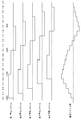
- FIG. 4 shows an example of control of the storage system group.
- the first storage system 40a to the fifth storage system 40e are included in the storage system group.
- the first power storage system 40a to the fifth power storage system 40e are controlled by the first power management system server 14a to the fifth power management system server 14e, respectively.
- the charge / discharge period is "0.5 seconds”
- the number of charge / discharge points is "5".
- Each power management system server 14 determines charge / discharge power "+2 kW" in "0.0" seconds. "+” Indicates discharge and "-" indicates charge.
- the first power storage system 40a performs "+2 kW” charge / discharge in “0.0" seconds
- the second power storage system 40 b performs “+2 kW” charge / discharge in “0.1” seconds
- the fifth power storage system 40e performs "+2 kW” charge and discharge in “0.4” seconds.
- each power management system server 14 determines the charge / discharge power “ ⁇ 1 kW” in “0.5” seconds.
- the first power storage system 40a performs "-1" kW charge / discharge in "0.5” seconds
- the second power storage system 40b performs “-1" kW charge / discharge in "0.6” seconds
- the fifth The storage system 40 e performs “ ⁇ 1 kW” charge / discharge in “0.9” seconds.
- the service linkage unit 300 of the first power management system server 14a is connected to the first group management system server 12a via the network 18, and executes communication with the first group management system server 12a.
- the receiving unit 510 receives a message from the first group management system server 12a.
- the message includes, for example, a table to be held in the storage unit 602.
- This table is generated in the first group management system server 12a, and is updated when the number of the plurality of power storage systems 40 managed by the first group management system server 12a changes.
- the group management system server 12 collectively manages a plurality of devices connected to each of the plurality of power management system servers 14.
- the table may be generated in the upper system server 10. In that case, it can be said that the receiving unit 510 receives a message including a table from the upper system server 10 via the first group management system server 12a.
- the message received by the receiving unit 510 may include information for specifying one of the adjustment power type A and the adjustment power type B to be used.
- the generation unit 604 uses the adjustment power type A or the adjustment power type B based on the designated information included in the message.
- the message received by the receiving unit 510 may include information on the number of charge and discharge points, and information on timing to be a starting point of the charge and discharge period.
- the transmission unit 512 transmits a message to the first group management system server 12a.
- the subject matter of the apparatus, system or method in the present disclosure comprises a computer.
- the computer executes the program to implement the functions of the apparatus, system, or method in the present disclosure.
- the computer includes, as a main hardware configuration, a processor that operates according to a program.
- the processor may be of any type as long as the function can be realized by executing a program.
- the processor is configured of one or more electronic circuits including a semiconductor integrated circuit (IC) or an LSI (Large Scale Integration).
- the plurality of electronic circuits may be integrated on one chip or may be provided on a plurality of chips.
- the plurality of chips may be integrated into one device or may be provided to a plurality of devices.
- the program is recorded in a non-transitory recording medium such as a computer readable ROM, an optical disc, a hard disk drive and the like.
- the program may be stored in advance in a recording medium, or may be supplied to the recording medium via a wide area communication network including the Internet and the like.
- FIG. 5 is a flowchart showing a control procedure by the first power management system server 14a.
- the frequency detection unit 600 detects the frequency of the power system 30 (S10).
- the generation unit 604 specifies charge / discharge power based on the detected frequency (S12).
- the generation unit 604 generates a random number (S14), and specifies the charge / discharge start time based on the random number during the charge / discharge period (S16).
- the transmitting unit 606 outputs an instruction including the charge and discharge power and the charge and discharge start time to the storage system 40 (S18).
- the frequency of the power system 30 is detected, and based on this, the power to be charged and discharged to the storage system 40 and the information on the time to start charging and discharging to the storage system 40 are generated. It is possible to control the rate of change of power according to the fluctuation of demand. Further, the difference between the frequency of power system 30 with respect to the reference frequency is detected, and based on this, the power to charge / discharge storage system 40 and information on the time to start charge / discharge to storage system 40 are generated. It is possible to control the rate of change of power according to the fluctuation of demand. Further, since the rate of change of the power is controlled according to the change of the power demand, it is possible to suppress the power system becoming unstable.
- the related information in which the power to be charged and discharged to the storage system 40 is associated with the frequency of the power system 30 or the difference in the frequency of the power system 30 with respect to the reference frequency is held, the process can be simplified. Further, since the related information in which the power to be charged and discharged to the storage system 40 is associated with the frequency of the power system 30 or the difference in the frequency of the power system 30 from the reference frequency is received, the related information can be updated. Further, since the related information is updated, even if the configuration of the VPP system 100 changes, the related information suitable for it can be used.
- one charge / discharge timing is specified by a random number generated with a predetermined probability, so the charge / discharge timings of the plurality of power storage systems 40 are uniformly distributed. It can be done.
- the outline of one aspect of the present disclosure is as follows.
- the power management system server 14 according to an aspect of the present disclosure is connected to a group management system server 12 that transmits a control command to a power storage system group including a power storage system 40 installed in each of a plurality of customers 16
- a power management system server 14 for controlling a power storage system 40 installed in a house 16, comprising: a frequency detection unit 600 for detecting a difference between the frequency of the power system 30 or the frequency of the power system 30 with respect to a reference frequency;
- the system includes the power for charging / discharging the storage system 40 based on the frequency or the difference detected at 600, and the generation unit 604 for generating information on the time for starting the charging / discharging of the storage system 40.
- the storage unit 602 may further include related information in which the power stored in the storage system 40 is associated with the frequency of the power system 30 or the difference in the frequency of the power system 30 with respect to the reference frequency.
- Generation unit 604 generates power to be charged / discharged to storage system 40 based on (1) the frequency or difference detected by frequency detection unit 600 and related information stored in storage unit 602, and (2) each During the period from when the storage system group starts charging / discharging to the target power of the storage system group to be achieved by charging / discharging the storage system 40, a time is generated to cause the storage system 40 to start charging / discharging.
- the generation unit 604 generates a time for causing the storage system 40 to start charging and discharging by specifying one timing with a random number generated with a predetermined probability among the plurality of timings defined during the period.
- Reception unit that receives related information that relates power to be charged / discharged to the storage system 40 with respect to the frequency of the power system 30 or the difference in frequency of the power system 30 with respect to the reference frequency from the upper system monitoring the power system 30 It further comprises 510.
- Another aspect of the present disclosure is a power control method.
- This method is connected to a group management system server 12 that transmits a control command to a storage system group including a storage system 40 installed in each of a plurality of customers 16 and also installed in the customer 16.
- a control method in the power management system server 14 for controlling the frequency of the power system 30 or the difference in the frequency of the power system 30 with respect to the reference frequency, and the storage system based on the detected frequency or the difference.
- Example 2 Next, Example 2 will be described.
- the present invention relates to a power management system that controls charging and discharging of a power storage system connected to a power system in accordance with an increase or decrease in power demand in the power system.
- the first embodiment even if the magnitude of the deviation between the frequency of the power system and the frequency of the commercial power source changes, the length of the charge / discharge period does not change.
- the second embodiment when the magnitude of the deviation between the frequency of the power system and the commercial power source frequency changes, the length of the charge and discharge period also changes.
- the configurations of the VPP system 100 and the customer 16 according to the second embodiment are the same as those shown in FIGS. 1 and 3. Here, differences from the first embodiment will be mainly described.
- the storage unit 602 in FIG. 2 holds related information in which the power to be charged / discharged to the storage system 40 and the charge / discharge period are associated with the frequency of the power system 30.
- the charge / discharge period is a period from when the storage system group starts charging / discharging to the target power of the storage system group to be achieved by charging / discharging of each storage system 40 until it reaches.
- the related information instead of the frequency of the power system 30, the difference of the frequency of the power system 30 with respect to the commercial power supply frequency may be used.
- the related information is held, for example, in the form of a table, but may be held in the form of a relational expression.
- FIG. 6 shows the data structure of a table stored in the storage unit 602. As illustrated, the relationship between the charge / discharge power and the charge / discharge period with respect to the detection frequency is shown. Here, it is assumed that the commercial power supply frequency is 60 Hz. The charge / discharge power is shown as in the first embodiment. In addition, as the absolute value of the difference between the frequency of power system 30 and the commercial power supply frequency increases, the charge and discharge period is extended. Return to FIG.
- the generation unit 604 extracts the charge and discharge power and the charge and discharge period by referring to the related information held in the storage unit 602 based on the frequency or the difference detected by the frequency detection unit 600. Further, as in the first embodiment, the generation unit 604 generates a random number to generate a charge / discharge start time that causes the storage system 40 to start charging / discharging during the charge / discharge period. The subsequent processing is the same as that described above, so the description is omitted here.
- the receiving unit 510 may receive a message including the table to be held in the storage unit 602 from the first group management system server 12a, as in the first embodiment.
- the charge / discharge period is changed according to the frequency of the power system 30 or the difference in frequency of the power system 30 with respect to the reference frequency, it is possible to adjust the speed of fluctuation of power.
- the related information in which the power to be charged / discharged to storage system 40 is associated with the charge / discharge period is held. You can In addition, the related information in which the power for charging / discharging the storage system 40 and the charging / discharging period are associated with the frequency of the power system 30 or the difference in the frequency of the power system 30 with respect to the reference frequency is received. It can be updated.
- one charge / discharge timing is specified by a random number generated with a predetermined probability, so the charge / discharge timings of the plurality of power storage systems 40 are uniformly distributed. It can be done.
- the outline of one aspect of the present disclosure is as follows. With respect to the frequency of the power system 30 or the difference in the frequency of the power system 30 with respect to the reference frequency, the power stored in the storage system 40 and the target power of the storage system group to be achieved by charging and discharging each storage system 40
- the system may further include a storage unit 602 that holds related information associated with a period from when the system group starts charging to discharging. (1) Based on the frequency or difference detected in the frequency detection unit 600 and the related information stored in the storage unit 602, the generation unit 604 generates power for charging and discharging the storage system 40 and a period ( 2) During the period, a time is generated to cause the storage system 40 to start charging and discharging.
- the power stored in the storage system 40 and the target power of the storage system group to be achieved by charging and discharging each storage system 40
- the system further includes a reception unit 510 that receives related information associated with a period from when the system group starts charging and discharging until it reaches from the upper system monitoring the power system 30.
- the frequency detection unit 600 to the transmission unit 606 are included in the first power management system server 14a.
- the frequency detection unit 600 to the transmission unit 606 may be included in the control device 216 of the storage system 40. In that case, it can be said that the control device 216 is a power control device. According to this modification, the degree of freedom of the configuration can be expanded.
- the number of charge and discharge timings is defined.
- fixed intervals may be defined.
- the fixed interval is fixed as 1/6 seconds. Therefore, since the charge / discharge timing is arranged at intervals of 1 ⁇ 6 second and the charge / discharge period ends in one second, the number of charge / discharge timings becomes “6”.
- each group becomes [0 to 0.166], [0.167 to 0.334],..., [0.835 to 1].
- 0.336 is generated as a random number, it is included in the third group. If the generated random number is 0.336, it belongs to the third group. Assuming that the charge / discharge timing of the first group is 14:15:00, the generation unit 604 determines the charge / discharge timing of 14: 15: 1/3 second. According to this modification, the degree of freedom of the configuration can be expanded.
Landscapes
- Engineering & Computer Science (AREA)
- Power Engineering (AREA)
- Supply And Distribution Of Alternating Current (AREA)
- Remote Monitoring And Control Of Power-Distribution Networks (AREA)
- Charge And Discharge Circuits For Batteries Or The Like (AREA)
Abstract
Un serveur de système de gestion d'énergie 14 est connecté à un serveur de système de gestion de groupe 12 qui transmet une instruction de commande à un groupe de systèmes de stockage d'électricité comprenant un système de stockage d'électricité 40 installé au niveau de chaque consommateur parmi une pluralité de consommateurs 16, et commande le système de stockage d'électricité 40 installé au niveau d'un consommateur 16. Une unité de détection de fréquence 600 détecte la fréquence d'un système d'alimentation 30 ou la différence de la fréquence du système d'alimentation 30 à partir d'une fréquence de référence. Une unité de génération 604, sur la base de la fréquence ou de la différence détectée dans l'unité de détection de fréquence 600, génère des informations concernant une puissance à charger dans le système de stockage d'électricité 40 ou à décharger à partir de ce dernier, et un moment auquel le système de stockage d'électricité 40 est amené à démarrer la charge ou la décharge.
Applications Claiming Priority (2)
| Application Number | Priority Date | Filing Date | Title |
|---|---|---|---|
| JP2017-251347 | 2017-12-27 | ||
| JP2017251347A JP7117546B2 (ja) | 2017-12-27 | 2017-12-27 | 電力制御装置、電力制御方法 |
Publications (1)
| Publication Number | Publication Date |
|---|---|
| WO2019131229A1 true WO2019131229A1 (fr) | 2019-07-04 |
Family
ID=67066478
Family Applications (1)
| Application Number | Title | Priority Date | Filing Date |
|---|---|---|---|
| PCT/JP2018/046185 Ceased WO2019131229A1 (fr) | 2017-12-27 | 2018-12-14 | Dispositif de commande de puissance, procédé de commande de puissance et programme |
Country Status (2)
| Country | Link |
|---|---|
| JP (1) | JP7117546B2 (fr) |
| WO (1) | WO2019131229A1 (fr) |
Families Citing this family (2)
| Publication number | Priority date | Publication date | Assignee | Title |
|---|---|---|---|---|
| JP7442127B2 (ja) * | 2020-01-30 | 2024-03-04 | パナソニックIpマネジメント株式会社 | 電力管理システム、電力管理方法及びプログラム |
| JP7723491B2 (ja) * | 2021-03-30 | 2025-08-14 | 大阪瓦斯株式会社 | 電源管理システム、燃料電池装置及び充放電装置 |
Citations (6)
| Publication number | Priority date | Publication date | Assignee | Title |
|---|---|---|---|---|
| WO2012057307A1 (fr) * | 2010-10-29 | 2012-05-03 | 三洋電機株式会社 | Dispositif de commande pour la gestion d'énergie |
| JP2014050232A (ja) * | 2012-08-31 | 2014-03-17 | Nec Saitama Ltd | 充電装置、充電方法及び充電プログラム |
| JP2015177623A (ja) * | 2014-03-14 | 2015-10-05 | パナソニックIpマネジメント株式会社 | 需給制御方法、需給制御装置、および、蓄電システム |
| WO2016017424A1 (fr) * | 2014-07-31 | 2016-02-04 | 日本電気株式会社 | Dispositif de commande, dispositif de commande d'appareil, procédé de rapport, et support d'enregistrement |
| JP2016092844A (ja) * | 2014-10-29 | 2016-05-23 | 中国電力株式会社 | 電力系統制御システム、電力系統制御システムの制御方法 |
| WO2016158900A1 (fr) * | 2015-03-30 | 2016-10-06 | 日本電気株式会社 | Appareil de commande, appareil de commande de dispositif, système de commande, procédé et programme de commande |
Family Cites Families (2)
| Publication number | Priority date | Publication date | Assignee | Title |
|---|---|---|---|---|
| WO2014208061A1 (fr) * | 2013-06-28 | 2014-12-31 | パナソニックIpマネジメント株式会社 | Dispositif de commande de distribution de courant et procédé de commande de distribution de courant |
| JP6341409B2 (ja) * | 2014-03-20 | 2018-06-13 | パナソニックIpマネジメント株式会社 | 電力管理方法、電力管理システム、電力管理装置及びプログラム |
-
2017
- 2017-12-27 JP JP2017251347A patent/JP7117546B2/ja active Active
-
2018
- 2018-12-14 WO PCT/JP2018/046185 patent/WO2019131229A1/fr not_active Ceased
Patent Citations (6)
| Publication number | Priority date | Publication date | Assignee | Title |
|---|---|---|---|---|
| WO2012057307A1 (fr) * | 2010-10-29 | 2012-05-03 | 三洋電機株式会社 | Dispositif de commande pour la gestion d'énergie |
| JP2014050232A (ja) * | 2012-08-31 | 2014-03-17 | Nec Saitama Ltd | 充電装置、充電方法及び充電プログラム |
| JP2015177623A (ja) * | 2014-03-14 | 2015-10-05 | パナソニックIpマネジメント株式会社 | 需給制御方法、需給制御装置、および、蓄電システム |
| WO2016017424A1 (fr) * | 2014-07-31 | 2016-02-04 | 日本電気株式会社 | Dispositif de commande, dispositif de commande d'appareil, procédé de rapport, et support d'enregistrement |
| JP2016092844A (ja) * | 2014-10-29 | 2016-05-23 | 中国電力株式会社 | 電力系統制御システム、電力系統制御システムの制御方法 |
| WO2016158900A1 (fr) * | 2015-03-30 | 2016-10-06 | 日本電気株式会社 | Appareil de commande, appareil de commande de dispositif, système de commande, procédé et programme de commande |
Also Published As
| Publication number | Publication date |
|---|---|
| JP7117546B2 (ja) | 2022-08-15 |
| JP2019118203A (ja) | 2019-07-18 |
Similar Documents
| Publication | Publication Date | Title |
|---|---|---|
| US10635058B2 (en) | Microgrid controller for distributed energy systems | |
| TW201716786A (zh) | 分配的能量系統邊緣單元 | |
| JP5946919B2 (ja) | 管理システム、管理方法及び機器 | |
| US11133677B2 (en) | Power controller, power control method, and program for controlling power | |
| JP6705498B2 (ja) | 制御装置、需給調整制御装置、蓄電装置、需給調整システム、制御方法、需給調整方法及びプログラム | |
| JP2013017284A (ja) | 電力制御システム、電気機器、および充放電制御部 | |
| JP7165874B2 (ja) | 電力制御方法、プログラム、電力制御システム、アグリゲーションシステム、及び通信端末 | |
| WO2019131229A1 (fr) | Dispositif de commande de puissance, procédé de commande de puissance et programme | |
| WO2019117071A1 (fr) | Système de gestion de groupes, dispositif de régulation de puissance, procédé de transmission et programme | |
| WO2019131228A1 (fr) | Dispositif et procédé de commande de puissance ainsi que programme | |
| WO2018225456A1 (fr) | Système de gestion d'énergie, appareil, procédé de réception et programme | |
| WO2018225455A1 (fr) | Système de gestion d'énergie, système de stockage d'énergie, procédé de transmission et programme | |
| JP7108876B2 (ja) | 群管理システム、電力制御装置、送信方法、プログラム | |
| WO2018225458A1 (fr) | Système de gestion de groupe, système de gestion de puissance, procédé de réception et programme | |
| WO2018225457A1 (fr) | Système de gestion de groupe, système de gestion de puissance, système de stockage d'énergie, procédé de transmission et programme | |
| JP6936097B2 (ja) | 電力管理装置および電力管理方法 | |
| JP6827205B2 (ja) | 群管理システム、電力制御装置、蓄電システム | |
| JP6876939B2 (ja) | 群管理システム、電力制御装置、蓄電システム | |
| JP2018207629A (ja) | 電力管理システム、燃料電池システム、受信方法、プログラム | |
| JP2020022317A (ja) | 制御システム、制御方法、プログラム |
Legal Events
| Date | Code | Title | Description |
|---|---|---|---|
| 121 | Ep: the epo has been informed by wipo that ep was designated in this application |
Ref document number: 18897573 Country of ref document: EP Kind code of ref document: A1 |
|
| NENP | Non-entry into the national phase |
Ref country code: DE |
|
| 122 | Ep: pct application non-entry in european phase |
Ref document number: 18897573 Country of ref document: EP Kind code of ref document: A1 |