WO2019131475A1 - Dispositif d'essai et procédé d'essai - Google Patents
Dispositif d'essai et procédé d'essai Download PDFInfo
- Publication number
- WO2019131475A1 WO2019131475A1 PCT/JP2018/047153 JP2018047153W WO2019131475A1 WO 2019131475 A1 WO2019131475 A1 WO 2019131475A1 JP 2018047153 W JP2018047153 W JP 2018047153W WO 2019131475 A1 WO2019131475 A1 WO 2019131475A1
- Authority
- WO
- WIPO (PCT)
- Prior art keywords
- test
- culture
- test piece
- sample
- case
- Prior art date
- Legal status (The legal status is an assumption and is not a legal conclusion. Google has not performed a legal analysis and makes no representation as to the accuracy of the status listed.)
- Ceased
Links
Images

Classifications
-
- B—PERFORMING OPERATIONS; TRANSPORTING
- B01—PHYSICAL OR CHEMICAL PROCESSES OR APPARATUS IN GENERAL
- B01L—CHEMICAL OR PHYSICAL LABORATORY APPARATUS FOR GENERAL USE
- B01L3/00—Containers or dishes for laboratory use, e.g. laboratory glassware; Droppers
- B01L3/56—Labware specially adapted for transferring fluids
- B01L3/565—Seals
-
- G—PHYSICS
- G01—MEASURING; TESTING
- G01N—INVESTIGATING OR ANALYSING MATERIALS BY DETERMINING THEIR CHEMICAL OR PHYSICAL PROPERTIES
- G01N33/00—Investigating or analysing materials by specific methods not covered by groups G01N1/00 - G01N31/00
- G01N33/48—Biological material, e.g. blood, urine; Haemocytometers
- G01N33/50—Chemical analysis of biological material, e.g. blood, urine; Testing involving biospecific ligand binding methods; Immunological testing
- G01N33/53—Immunoassay; Biospecific binding assay; Materials therefor
- G01N33/543—Immunoassay; Biospecific binding assay; Materials therefor with an insoluble carrier for immobilising immunochemicals
- G01N33/54366—Apparatus specially adapted for solid-phase testing
- G01N33/54386—Analytical elements
-
- B—PERFORMING OPERATIONS; TRANSPORTING
- B01—PHYSICAL OR CHEMICAL PROCESSES OR APPARATUS IN GENERAL
- B01L—CHEMICAL OR PHYSICAL LABORATORY APPARATUS FOR GENERAL USE
- B01L3/00—Containers or dishes for laboratory use, e.g. laboratory glassware; Droppers
- B01L3/50—Containers for the purpose of retaining a material to be analysed, e.g. test tubes
- B01L3/502—Containers for the purpose of retaining a material to be analysed, e.g. test tubes with fluid transport, e.g. in multi-compartment structures
- B01L3/5023—Containers for the purpose of retaining a material to be analysed, e.g. test tubes with fluid transport, e.g. in multi-compartment structures with a sample being transported to, and subsequently stored in an absorbent for analysis
-
- C—CHEMISTRY; METALLURGY
- C12—BIOCHEMISTRY; BEER; SPIRITS; WINE; VINEGAR; MICROBIOLOGY; ENZYMOLOGY; MUTATION OR GENETIC ENGINEERING
- C12M—APPARATUS FOR ENZYMOLOGY OR MICROBIOLOGY; APPARATUS FOR CULTURING MICROORGANISMS FOR PRODUCING BIOMASS, FOR GROWING CELLS OR FOR OBTAINING FERMENTATION OR METABOLIC PRODUCTS, i.e. BIOREACTORS OR FERMENTERS
- C12M23/00—Constructional details, e.g. recesses, hinges
- C12M23/26—Constructional details, e.g. recesses, hinges flexible
-
- C—CHEMISTRY; METALLURGY
- C12—BIOCHEMISTRY; BEER; SPIRITS; WINE; VINEGAR; MICROBIOLOGY; ENZYMOLOGY; MUTATION OR GENETIC ENGINEERING
- C12M—APPARATUS FOR ENZYMOLOGY OR MICROBIOLOGY; APPARATUS FOR CULTURING MICROORGANISMS FOR PRODUCING BIOMASS, FOR GROWING CELLS OR FOR OBTAINING FERMENTATION OR METABOLIC PRODUCTS, i.e. BIOREACTORS OR FERMENTERS
- C12M23/00—Constructional details, e.g. recesses, hinges
- C12M23/34—Internal compartments or partitions
-
- C—CHEMISTRY; METALLURGY
- C12—BIOCHEMISTRY; BEER; SPIRITS; WINE; VINEGAR; MICROBIOLOGY; ENZYMOLOGY; MUTATION OR GENETIC ENGINEERING
- C12M—APPARATUS FOR ENZYMOLOGY OR MICROBIOLOGY; APPARATUS FOR CULTURING MICROORGANISMS FOR PRODUCING BIOMASS, FOR GROWING CELLS OR FOR OBTAINING FERMENTATION OR METABOLIC PRODUCTS, i.e. BIOREACTORS OR FERMENTERS
- C12M33/00—Means for introduction, transport, positioning, extraction, harvesting, peeling or sampling of biological material in or from the apparatus
- C12M33/02—Means for introduction, transport, positioning, extraction, harvesting, peeling or sampling of biological material in or from the apparatus by impregnation, e.g. using swabs or loops
-
- G—PHYSICS
- G01—MEASURING; TESTING
- G01N—INVESTIGATING OR ANALYSING MATERIALS BY DETERMINING THEIR CHEMICAL OR PHYSICAL PROPERTIES
- G01N33/00—Investigating or analysing materials by specific methods not covered by groups G01N1/00 - G01N31/00
- G01N33/48—Biological material, e.g. blood, urine; Haemocytometers
- G01N33/50—Chemical analysis of biological material, e.g. blood, urine; Testing involving biospecific ligand binding methods; Immunological testing
- G01N33/53—Immunoassay; Biospecific binding assay; Materials therefor
- G01N33/543—Immunoassay; Biospecific binding assay; Materials therefor with an insoluble carrier for immobilising immunochemicals
- G01N33/54366—Apparatus specially adapted for solid-phase testing
- G01N33/54386—Analytical elements
- G01N33/54387—Immunochromatographic test strips
-
- G—PHYSICS
- G01—MEASURING; TESTING
- G01N—INVESTIGATING OR ANALYSING MATERIALS BY DETERMINING THEIR CHEMICAL OR PHYSICAL PROPERTIES
- G01N33/00—Investigating or analysing materials by specific methods not covered by groups G01N1/00 - G01N31/00
- G01N33/48—Biological material, e.g. blood, urine; Haemocytometers
- G01N33/50—Chemical analysis of biological material, e.g. blood, urine; Testing involving biospecific ligand binding methods; Immunological testing
- G01N33/53—Immunoassay; Biospecific binding assay; Materials therefor
- G01N33/543—Immunoassay; Biospecific binding assay; Materials therefor with an insoluble carrier for immobilising immunochemicals
- G01N33/54366—Apparatus specially adapted for solid-phase testing
- G01N33/54386—Analytical elements
- G01N33/54387—Immunochromatographic test strips
- G01N33/54388—Immunochromatographic test strips based on lateral flow
-
- B—PERFORMING OPERATIONS; TRANSPORTING
- B01—PHYSICAL OR CHEMICAL PROCESSES OR APPARATUS IN GENERAL
- B01L—CHEMICAL OR PHYSICAL LABORATORY APPARATUS FOR GENERAL USE
- B01L2200/00—Solutions for specific problems relating to chemical or physical laboratory apparatus
- B01L2200/06—Fluid handling related problems
- B01L2200/0689—Sealing
-
- B—PERFORMING OPERATIONS; TRANSPORTING
- B01—PHYSICAL OR CHEMICAL PROCESSES OR APPARATUS IN GENERAL
- B01L—CHEMICAL OR PHYSICAL LABORATORY APPARATUS FOR GENERAL USE
- B01L2300/00—Additional constructional details
- B01L2300/08—Geometry, shape and general structure
- B01L2300/0809—Geometry, shape and general structure rectangular shaped
- B01L2300/0825—Test strips
-
- B—PERFORMING OPERATIONS; TRANSPORTING
- B01—PHYSICAL OR CHEMICAL PROCESSES OR APPARATUS IN GENERAL
- B01L—CHEMICAL OR PHYSICAL LABORATORY APPARATUS FOR GENERAL USE
- B01L2300/00—Additional constructional details
- B01L2300/12—Specific details about materials
- B01L2300/123—Flexible; Elastomeric
-
- B—PERFORMING OPERATIONS; TRANSPORTING
- B01—PHYSICAL OR CHEMICAL PROCESSES OR APPARATUS IN GENERAL
- B01L—CHEMICAL OR PHYSICAL LABORATORY APPARATUS FOR GENERAL USE
- B01L3/00—Containers or dishes for laboratory use, e.g. laboratory glassware; Droppers
- B01L3/50—Containers for the purpose of retaining a material to be analysed, e.g. test tubes
- B01L3/502—Containers for the purpose of retaining a material to be analysed, e.g. test tubes with fluid transport, e.g. in multi-compartment structures
- B01L3/5029—Containers for the purpose of retaining a material to be analysed, e.g. test tubes with fluid transport, e.g. in multi-compartment structures using swabs
Definitions
- the present invention relates to a test device and a test method for performing a biomolecular detection test using test strip paper.
- test device in which a test piece to which a reagent or an indicator is attached is absorbed into a test piece, and a test piece in a state in which the reagent or the like and the liquid to be measured have reacted is determined visually.
- test device used for an immunological test by a method (for example, an immunochromatography method) for detecting a biological molecule such as an antigen in a living body, wherein a porous test strip is used as a reagent It is known to apply the property of flowing slowly while melting (capillary phenomenon).
- the immunochromatography method is an immunoassay based on an antigen-antibody reaction, in which a porous test strip on which a labeled antibody and a capture antibody are immobilized in advance is prepared, and one end of the test strip is made to absorb a sample solution.
- a biomolecule such as an antigen
- a sample solution moves in a membrane shape while forming an immune complex with a labeled antibody by capillary action. Then, when the immune complex is trapped by the capture antibody, the colored particles derived from the labeled antibody become concentrated and become colored, so that they are visually determined as the degree of the antigen contained in the sample.
- a simple and quick test can be performed by a simple test instrument, and is currently widely used for detection of influenza virus, O157, etc., pregnancy determination and the like.
- test strip on which a labeled antibody and a capture antibody are immobilized in advance is enclosed in a rectangular case having a dropping window of a sample liquid and a detection window for visualizing the state of the test strip.
- a thing etc. are known (for example, refer to patent documents 1).
- the bacterium is collected from the environment to which the bacterium is attached, and cultured in a considerable number (for example, cultured 1000 times). Then, it is necessary to use the test solution by dropping the cultured sample liquid on the test device.
- An object of the present invention is to provide a test instrument and a test method capable of preventing scattering and leakage of a sample liquid and performing an inspection simply and safely in view of such a situation.
- the present invention relates to a culture means capable of culturing a sample in a sealed state, a test strip capable of absorbing a sample fluid in the culture means, and a separation means capable of separating the test strip and the sample fluid in a noncontact state.
- An opening means capable of forming a channel through which the sample liquid reaches the test piece by opening at least a part of the separation means, a part of at least the separation means side of the test piece, and the culture means And at least a part of the case and a case integrally sealing the separation means.
- the present invention is a test method for detecting a biomolecule using a test device in which a culture means for a sample and a test piece are held in an integral type case, and the culture means and the test piece Collecting the sample in a separated state and culturing in the culture means in a closed state; releasing the separation between the culture means and the test piece while maintaining the sealed state by the case; It is a test method characterized by including a step of causing the test piece to absorb a liquid without exposing the liquid to the outside and a step of visually determining the test piece.
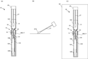
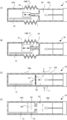
- A A top view of a test device according to an embodiment of the present invention, (B) a top view of a test piece, (C) a side view of the test piece, and (D) a side cross-sectional view of the test device. It is a figure which shows the test method using the test device which concerns on embodiment of this invention, (A) Side sectional view of test device, (B) The figure which shows the state of the collection by collection means, (C) The state in culture. It is a side sectional view showing.
- test device which concerns on embodiment of this invention
- A Side sectional view of test device
- B Partially enlarged view of side cross section of test device
- C Test device It is a partially enlarged view of a side cross section
- D is a top view of a test device.
- A Side sectional view of test device
- B Partially enlarged view of side cross section of test device
- C Test device It is a partially enlarged view of a side cross section
- D is a top view of a test device.
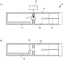
- D is a schematic diagram showing the modification of the test device concerning the embodiment of the present invention.
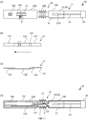
- FIG. 1 is a view showing a test device 10 according to the present embodiment
- FIG. 1 (A) is a top view of the appearance
- FIG. 1 (B) is a top view showing an example of a test piece 13.
- (C) is a side view of the test strip 13
- (D) is a side sectional view showing a state before the test including the unused state of the test device 10 (before dropping the sample liquid S2 onto the test strip 13). It is.
- the test device 10 of the present embodiment has a culture means 11, a test piece 13, a separation means 15, an opening means 17 and a case 19.
- the culture means 11 is, for example, a sealing means (for example, a screw-type lid, etc.) for sealing the solution storage portion 19C, the flow path 23 of the sample liquid S2 and the solution storage portion 19C as shown in FIG. ) Has 25.
- a sealing means for example, a screw-type lid, etc.
- the culture solution S1 is stored in the solution storage section 19C before the test, and the culture solution S1 can culture a considerable number (for example, 1000 times) of samples. Further, the solution storage section 19C can continue to store a solution containing a considerable number of samples after culturing the samples (hereinafter, this will be referred to as "sample liquid S2").
- the solution storage unit 19C can store the collection means 27 (in this example, a cotton swab or the like) from which the sample is collected as it is.
- the collecting means 27 is, for example, a rod-like member (in this example, a cotton swab or the like) having a collecting portion 27A at one end.
- the culture means 11 contains the collection means 27 in the solution storage part 19C, immerses the collection part 27A (the tip of the cotton swab) in the culture solution S1, and seals the collection means 27 by sealing with the sealing means (lid) 25. And the sample can be cultured.
- the solution container 19C may be provided with a metal plate 31 or the like having a high thermal conductivity on a part of the outer surface thereof.
- the metal plate 31 facilitates the transfer of external heat to the inside of the solution storage portion 19C at the time of culture, and the response of culture temperature control is improved, so that culture can be facilitated.
- the lid 25 is attached to the rear end (the end opposite to the collecting portion 27A) of the collecting means 27. That is, when the collection means 27 from which the sample is collected is housed in the solution container 19C, and the lid 25 is attached to the rear end of the solution container 19C, the collector 27A is configured to be submerged in the culture solution S1. .
- the test strip 13 is, for example, a band-like porous member capable of absorbing the sample fluid S2 cultured by the culture means 11, and in this example, is a known test strip used in the immunochromatographic test.
- the sample pad 131 which becomes a dropping part of the sample liquid S2, an antibody labeled with colored particles such as gold colloid (labeled antibody)
- a membrane filter 135 on which a conjugate pad 133 containing a complementary antibody (T) and a control antibody (C) is applied and fixed linearly in the width direction of the band, an absorption pad 137 for sucking up the dropped sample liquid S2, It is the member laminated
- the sample liquid S2 dropped on the sample pad 131 moves in the direction of the arrow toward the absorption pad 137.
- the test strip 13 is not limited to the laminated structure in which a part of each of the sample pad 131, the conjugate pad 133, the membrane filter 135, and the absorption pad 137 is overlapped as shown in FIG. A configuration in which regions corresponding to each of the sample pad 131, the conjugate pad 133, the membrane filter 135, and the absorption pad 137 are continuously arranged so as to be adjacent to each other along the longitudinal direction of one strip of porous member; Alternatively, only a part of these configurations may be stacked.
- test piece 13 having a laminated structure as shown in FIG. 6C is taken as an example, but in the case of a single (or partial configuration overlapping) strip-like test piece 13, the sample
- the configuration described as each of the pad 131, the conjugate pad 133, the membrane filter 135, and the absorption pad 137 is replaced with a region corresponding to each configuration.
- sample pad 131 it is read as "an area corresponding to sample pad 131".
- the case 19 in this example includes a test piece storage 19A, a connection 19B, and a solution storage 19C. That is, the solution storage portion 19C of the culture means 11 is integrally provided without a gap with the test piece storage portion 19A.
- the test strip storage portion 19A has, for example, a substantially rectangular parallelepiped shape, and the test strip 13 is stored therein.
- a judgment window capable of judging (visually recognizing) the judgment region of the test piece 13 (namely, the membrane filter 135) 191 and a transpiration window 193 for preventing backflow of the sample liquid S2 in the test piece 13 are provided.
- the judgment window 191 is covered with a transparent resin, glass or the like, and the transpiration window 193 is open, and although it is in communication (opened) with the inside, it is provided small enough to vaporize the vaporized sample liquid S2.
- the test piece 13 inside is configured to be inaccessible from these windows.
- a guide G for visual judgment may be provided in a part of the judgment window 191 by printing or sticker attachment.
- the guide G is a scale in which the levels of color density are divided into a plurality of steps (for example, 10 steps) so as to be an index of the coloration state of (the antibody for control of) the membrane filter 135. Also, only one reference color may be shown instead of the color shading level.
- the connecting portion 19B is a portion which closely adheres to both the test piece containing portion 19A and the solution containing portion 19C without a gap and integrally connects the test piece containing portion 19A and the solution containing portion 19C.
- the connecting portion 19B is configured to be, for example, flexible and deformable.
- the connection portion 19B has a bellows structure so as to connect and hold the test piece storage portion 19A and the solution storage portion 19C in a relatively bendable manner.
- the test device 10 of this embodiment is arranged such that the culture means 11 and the test strip 13 are aligned along the longitudinal direction of the case 19.
- the culture solution S1 of the culture means 11 or the sample liquid S2 after culture and the test piece 13 are integrally sealed and held by the case 19 (the test piece storage portion 19A, the connection portion 19B and the solution storage portion 19C)
- the separation means 15 separates in a non-contact state as shown in FIG.
- the separation means 15 is, for example, a sealing member which is accommodated inside the connection portion 19B of the case 19 and prevents the sample liquid S2 from touching the test strip 13 until a predetermined time (timing of the test). It is provided as part of the case 19 (integrally with the case 19).
- the solution storage section 19C is provided with the flow path 23 of the sample liquid S2 on the side closer to the test piece 13 (the opposite side to the lid 25).
- the flow path 23 has, for example, a shape that is smaller in diameter than the cylindrical solution storage unit 19C and tapers away from the solution storage unit 19C, and an appropriate amount of sample liquid S2 in the solution storage unit 19C, It is configured to be capable of dropping on the end portion (sample pad 131) of the test piece 13.
- the shape of the flow path 23 is not limited to that shown in the drawings, and any shape and configuration that allows the sample liquid S2 to flow out toward the test strip 13 may be used.
- the separation means 15 in this case is in contact with the outflow side end (opening) of the flow path 23 of the culture means 11 above the end (sample pad 131) of the test piece 13 on the culture means 11 side. Seal the part.
- the separation means 15 is, for example, a sealing member formed so as to draw a part of the case 19 (the inner wall of the test piece storage 19A into the internal space of the connection 19B).
- At least one of the flow path 23 and the separation means (sealing member) 15 or their contact portion and / or the vicinity thereof is formed in a thin-walled structure (see FIG. 3B) .
- the thin-walled structure is, for example, a structure in which the thickness of the member is thinner than in other portions to weaken the strength, or a structure in which a cut is formed in the member to guide bending and separation in a predetermined direction. is there.
- the contact portion of the separation means 15 and the flow path 23 has a fragile structure V, and is broken (cut off) by an external force of bending, folding or pinching with the finger of the operator.
- the separation means (sealing member) 15 separates from the flow path 23).
- the flow path 23 and the test strip storage portion 19A communicate with each other, and the sample liquid S2 is dropped onto the sample pad 131 of the test strip 13.
- the opening means 17 is a connecting portion 19B which connects the test piece containing portion 19A and the solution containing portion 19C and holds the both in a foldable manner. That is, the operator bends the solution storage portion 19C with respect to the test piece storage portion 19A, for example, with the bellows opening means 17 (connecting portion 19B) as the center (for example, the solution storage portion 19C shown in FIG. Can be folded upwards, whereby the separation means 15 is released from the flow path 23.
- the test device 10 of the present embodiment includes at least a portion of the test strip 13 on the side of the separation means 15 (the portion of the sample pad 131 which is a region to which the sample liquid S2 is dropped) and at least a portion of the culture means 11 (The solution storage portion 19C, the flow path 23, the tip opening of the flow path 23) and the separation means (seal member) 15 are integrally sealed by the case 19 and in the state before the start of the test, the culture solution S1 or the sample liquid S2 and the test strip 13 are separated by the separation means 15.
- the test device 10 releases the separated state (sealed state) of the sample liquid S2 and the test piece 13 by the separating means (sealing member) 15, and the sample liquid S2 stored in the solution storage portion 19C of the culture means 11 It has an opening means 17 capable of forming a flow path reaching the test piece 13.
- the opening means 17 in this example is a part (connecting portion 19B) of the case 19 which can be deformed while maintaining the seal.
- the opening means 17 (connecting portion 19B) is configured to open the separation means 15 while maintaining the state sealed inside the case 19 by changing the state during the test.
- the opening means 17 can be deformed in a state in which the sealing is maintained by applying an external force, whereby the separation means 15 is opened in a state sealed inside the case 19.
- the flow path 23 and the inside of the test piece storage 19A communicate with each other by opening the separation means 15, and the sample liquid S2 is dropped on the sample pad 131 of the test piece 13 without being exposed to the outside of the case 19.
- the separating means 15 and / or the fragile structure V in the vicinity thereof are configured to be more easily broken than the other regions so that the flow path 23 and the separating means 15 can be easily separated.
- the configuration that contributes to the opening of the opening means 17 (here, the fragile structure V) is also a part of the opening means 17.
- the open means 17 (connecting part 19B) has a bellows structure in this example, it may be, for example, a tube structure which can be bent or deformed inward by external force.
- At least the opening means 17 may be configured to have transparency so that the separating means 15 and the vicinity thereof can be visually recognized from the outside. The operator can easily confirm the open state of the separating means 15, and reliable open operation is possible.
- the test can be performed by an employee or the like of the restaurant, for example, at a restaurant or the like regardless of a specialized organization or a skilled worker.
- the transpiration window 193 is provided in the case 19 in order to prevent the backflow of the sample liquid S 2 in the test piece 13.
- the transpiration window 193 may not be provided as long as the backflow can be prevented by a method such as devising the shape (for example, making it sufficiently long in the longitudinal direction).
- the inside of the case 19 can be made into a substantially complete sealed space. That is, the test strip 13, the solution storage portion 19C and the flow path 23 of the culture means 11, and the separation means 15 can be sealed, which is more suitable for preventing the sample liquid S2 from scattering and leaking.
- ⁇ Test method for detection of biomolecules> With reference to FIG. 2 and FIG. 3, the detection test method of the biomolecule using the test device 10 of this embodiment is demonstrated.
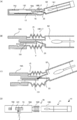
- FIGS. 3B and 3C are enlarged views in the vicinity of the connecting portion 19B.
- a sample is collected in a collection environment (for example, a kitchen of a restaurant or the like) in which the presence of a target (to be detected) biomolecule (for example, pathogenic E. coli such as O157) is suspected. That is, the unused test device 10 of the present embodiment is prepared. As described above, the test device 10 is one in which the culture means 11 and the test piece 13 are held by the integral type case 19 (FIG. 6A).
- a target for example, pathogenic E. coli such as O157
- the sample is collected in a state in which the culture means 11 and the test piece 13 are separated, and cultured in the culture means 11 in a closed state.
- the lid 25 at the end of the culture means 11 is removed, the collection means 27 is extracted, and a desired place is wiped off by the collection part 27A of the collection means 27 to attach the sample to the collection part 27A (FIG. B)).
- the collecting unit 27A (the tip of the cotton swab) is configured to be submerged in the culture solution S1 with the lid 25 closed, and can culture the sample while the collecting means 27 is housed in a sealed state.
- the test device 10 is stored, for example, in a constant temperature incubator 50 or the like, and left for a predetermined time (the same figure (C)).
- the antigen is pathogenic E. coli such as O157, for example, it is cultured about 1000 times by culturing it at a temperature of 37 ° C. for 3 hours.
- the separation between the culture means 11 and the test strip 13 is released while maintaining the sealed state by the case 19, and the sample liquid S2 is absorbed to the test strip 13 without being exposed to the outside.
- test device 10 is taken out from the constant temperature incubator 50 or the like, and in the state as it is (without opening the lid 25), the portion of the opening means 17 (connecting portion 19B) of the bellows structure is bent (FIG. 3A) .
- the separation means 15 is folded and separated in the inside of the connection portion 19B while maintaining the sealed state by the case 19 It is released.
- the separation means (sealing means) 15 separates from the flow path 23, and the flow path 23 and the inside of the test strip storage portion 19A communicate with each other. Thereby, the sample liquid S2 is dropped onto the sample pad 131 of the test piece 13 while maintaining the sealed state by the case 19 (FIG. 3A).
- the sample solution S2 is absorbed by the membrane filter 135 via the sample pad 131 and the conjugate pad 133 (see FIG. 1 (B), FIG. 1 (C)).
- the antigen moves in the membrane filter 135 while forming an immune complex with the labeled antibody by capillary action.
- the immune complex is trapped by the capture antibody, the colored particles derived from the labeled antibody become concentrated and become colored, so that they are visually determined as the degree of the antigen contained in the sample.
- the determination is performed, for example, with reference to a guide determination guide G provided in a part of the determination window 191 and compared with the colored state of the membrane filter 135.
- the comparison may be performed using a guide plate printed with, for example, one or more levels of shades of color separate from the test device 10.
- the coloration state of the membrane filter 135 and the guide (guide plate) may be photographed by a portable terminal (for example, a smartphone or the like), and the image may be transmitted to the determination organization for determination.
- the captured image may be captured using an application program for determination, etc., so that the determination can be made immediately.
- the test method using the test device 10 of the present embodiment it is possible to carry out from the culture of the sample to the dropping of the sample liquid S2 onto the test piece 13 in the sealed environment.
- the step of dropping the sample liquid S2 which has conventionally been likely to be exposed to the sample liquid S2 can be completed in the case 19 of the substantially sealed environment. Therefore, even if the sample liquid S2 contains a high concentration of bacteria, the sample liquid S2 can be prevented from scattering and leaking without being exposed to the outside, and consequently, it can be prevented to the worker and the work environment. Secondary pollution and infection can be prevented.
- the test can be performed by an employee or the like of the restaurant, for example, at a restaurant or the like regardless of a specialized organization or a skilled worker.
- the comparison image of the coloration state of the membrane filter 135 and the guide (guide plate) is transmitted to a specialized organization or taken into a dedicated application program or the like to make judgment, thereby avoiding variation in judgment by the operator. An accurate determination can be made.
- 4 to 6 are schematic side sectional views mainly showing modified examples of the separating means 15 and the opening means 17 in the test device 10 of the present embodiment. 4 to 6, parts of the test piece 13 and the test piece storage portion 19A are omitted, but the omitted configuration (for the test piece 13 and the test piece storage portion 19A, FIG. The same as shown in.
- the test strip 13 and the sample liquid S2 are integrally housed in the case 19, and the separation unit 15 does not at least the test strip 13 and the sample liquid S2. It is configured to be separable in the contact state (the same figure (A)), and at the time of testing, the operator operates the opening means 17 at an arbitrary timing to open (at least a part of) the separation means 15 Thus, it is only necessary that the flow path can be formed such that the sample liquid S2 reaches the test piece 13 without being exposed to the outside of the case 19 (FIG. 6B).
- the fragile structure V of the opening means 17 is a cutting means 15 (a test piece for facilitating bending and separation in a predetermined direction (upward in the same figure). It may be a structure formed in a part of the housing portion 19A) or in the flow path 23 or a member in the vicinity thereof.
- the opening means 17 has, for example, a connecting portion 19B (17A) configured to be extensible and contractible in the longitudinal direction of the case 19, and the flow path 23 of the culture means 11 from the test strip 13 side. It may be a needle-like member 17B protruding to the side, and the separation means 15 may be the bottom of the solution storage portion 19C.
- the needle-like member 17B is, for example, integrally connected with the test piece receiving portion 19A, and in an unused state, the needle-like member 17B and the separating means 15 are separated. Then, by shrinking the connecting part 19B after the culture, the needle-like member 17B is configured to destroy (deletion, pierce) at least a part of the separation means 15.
- the needle-like member 17B may be made to advance toward the separating means 15 by an operation from the outside.
- the other end side (end side away from the separating means 15) of the needle-like member 17B is led out of the case 19, etc., and the operator manipulates the end taken out to operate the needle-like member 17B. It is moved toward the separating means 15.
- the connecting portion 19B of the case 19 may be configured not to be deformed.
- the needle-like member 17B may advance from the solution storage portion 19C side to the test strip storage portion 19A side and destroy (deletion) at least a part of the separation means 15.
- the opening means 17 is integrally formed at the bottom of the solution storage portion 19C to be the separating means 15 or the like, and the opening means 17 is broken with respect to the separating means 15.
- the solution storage unit 19C and the test strip storage unit 19A may be communicated with each other by causing a part of the separation unit 15 (a joint portion with the opening unit 17) to be lost by, for example, the like.
- the end of the opening means 17 opposite to the separating means 15 is led out of the case 19 and the opening means 17 is bent by the operation of the lead-out portion.
- the connecting portion 19B of the case 19 may be formed into, for example, a bellows shape or a tube shape as shown in FIG.
- the opening means 17 may be bent by
- the opening means 17 of the present embodiment may be housed in the case 19 (the connecting portion 19B).
- the separation means 15 is deficient and the area to be opened is controlled by making only a part of the solution storage part 19C into the fragile structure V (fragile It is possible to concentrate on the structure V and its vicinity).
- the flow path 23 as shown in FIG. 6 (A) is formed in both FIG. 6 (B) and FIG. 6 (C), and the separation means 15 may be a sealing member covering the flow path 23 Good.
- the separating means 15 may be a plug member for closing the end of the flow path 23.
- the same figure (A) is a structure which inserts the separation means (plug member) 15 in the flow path 23, and the figure (B) inserts the tip of the flow path 23 in the separation means (plug member) 15. It is a structure.
- the separation means 15 and the flow path 23 may be detachably fitted by relatively moving the both in the longitudinal direction of the case 19, or even when one is screwed into the other Good.
- the separation means 15 may be connected to the test strip storage portion 19A, and the separation means (plug member) 15 may be attached or detached by the operation of the opening means (connection portion 19B).
- the opening means 17 is, for example, a connecting portion 19B of the case 19 capable of bending and deforming so as to extend and contract in the longitudinal direction of the case 19 or to rotate around a rotation axis along the longitudinal direction. By doing this, the separation means 15 is separated from the flow path 23.
- separating means 15 may be led out of the case 19 and the separating means 15 may be configured to be removable by the operation of the lead-out portion.
- the solution container 19C of the culture means 11 is configured to be flexible and deformable, and an external force is applied from the outside of the solution container 19C (the solution container 19C is
- the fragile structure V provided in the flow path 23 or a part of the solution storage portion 19C may be destructed (broken) by pressing.
- the fragile structure V to be deficient and a part of the flow path 23 or the solution storage portion 19C in the vicinity thereof are the separation means 15, and the bending deformation of the culture means 11 (solution storage portion 19C) configured to be pressable.
- the possible area is the opening means 17.
- the amount of the sample liquid S2 to be dropped on the test piece 13 may not be stable if too large, and the drop amount of the sample liquid S2 may be As an example, 100 ⁇ l to 140 ⁇ l, and depending on the shape of the test strip 13, 250 ⁇ l to 500 ⁇ l may be preferable.
- the shape of the flow path 23, the open position when the solution storage portion 19C is directly opened, the position and shape of the fragile structure V, the shape of the opening means 17 and the separating means 15, and The aspect is appropriately selected such that, when there is an appropriate amount for dropping the sample liquid S2, the appropriate amount can be dropped.
- the configuration is not limited to dropping a part of the sample liquid S2 stored in the solution storage portion 19C onto the test piece 13, but when the separation means 15 is opened by the opening means 17, as shown in FIG.
- a part of the test strip 13 (for example, only the sample pad 131) may be entirely immersed in the sample liquid S2.
- the partition 19D is provided in the test strip storage portion 19A, and the test strip 13 other than the sample pad 131 is configured not to be immersed in the sample fluid S2 and to move the sample fluid S2 in the test strip 13.
- the determination window 191 is not provided, and the test piece storage portion 19A or the entire case is transparent and the inside is visible. It may be configured to be
- test device 10 used for the detection test of biomolecules by the immunochromatography method has been described as an example, but not limited to the immunochromatography method
- the sample solution S2 cultured by the culture means 11 is absorbed
- a test strip 13 capable of displaying any result or a test device using the test strip 13 capable of absorbing the sample liquid S2 (within the culture means 11) contained in the culture means 11 and displaying any result Can be implemented similarly.
- test device 10 of the present invention is not limited to the above-described embodiment, and it goes without saying that various modifications can be added without departing from the scope of the present invention.
- test apparatus 11 culture means 13 test piece 15 separation means 17 opening means 17B needle-like member 19 case 19A test piece storage part 19B connection part 19C solution storage part 23 flow path 25 lid 27 collection means 27A collection part 31 metal plate 50 constant temperature culture 131 sample pad 133 conjugate pad 135 membrane filter 137 absorption pad 191 judgment window 193 transpiration window S1 culture solution S2 sample liquid V fragile structure
Landscapes
- Health & Medical Sciences (AREA)
- Life Sciences & Earth Sciences (AREA)
- Chemical & Material Sciences (AREA)
- Engineering & Computer Science (AREA)
- Immunology (AREA)
- Biomedical Technology (AREA)
- Wood Science & Technology (AREA)
- Bioinformatics & Cheminformatics (AREA)
- Organic Chemistry (AREA)
- Zoology (AREA)
- General Health & Medical Sciences (AREA)
- Molecular Biology (AREA)
- Microbiology (AREA)
- Biotechnology (AREA)
- Biochemistry (AREA)
- Hematology (AREA)
- Urology & Nephrology (AREA)
- Clinical Laboratory Science (AREA)
- General Engineering & Computer Science (AREA)
- Genetics & Genomics (AREA)
- Sustainable Development (AREA)
- Analytical Chemistry (AREA)
- Cell Biology (AREA)
- Food Science & Technology (AREA)
- Medicinal Chemistry (AREA)
- Physics & Mathematics (AREA)
- General Physics & Mathematics (AREA)
- Pathology (AREA)
- Chemical Kinetics & Catalysis (AREA)
- Apparatus Associated With Microorganisms And Enzymes (AREA)
Abstract
La présente invention a pour objet de réaliser un dispositif d'essai et un procédé d'essai qui sont capables d'empêcher un échantillon liquide d'être dispersé et de fuir, et de réaliser simplement et en toute sécurité une inspection. Le dispositif d'essai (10) selon l'invention comporte : un moyen de culture (11) apte à cultiver un échantillon dans un état scellé ; une pièce d'essai apte à absorber un échantillon liquide (S2) cultivé par le moyen de culture ; un moyen de séparation (15) apte à séparer la pièce d'essai (13) et l'échantillon liquide (S2) dans un état sans contact ; un moyen d'ouverture (17) apte à former un passage de fluide à travers lequel l'échantillon liquide (S2) atteint la pièce d'essai (13) en ouvrant au moins une portion du moyen de séparation (15) ; un boîtier qui scelle d'un seul tenant au moins une portion côté moyen de séparation (15) de la pièce d'essai (15), au moins une portion du moyen de culture (11) et le moyen de séparation.
Priority Applications (3)
| Application Number | Priority Date | Filing Date | Title |
|---|---|---|---|
| US16/955,446 US11857971B2 (en) | 2017-12-28 | 2018-12-21 | Test device and test method |
| EP18893370.9A EP3726216B1 (fr) | 2017-12-28 | 2018-12-21 | Dispositif d'essai et procédé d'essai |
| CN201880084732.XA CN111527408B (zh) | 2017-12-28 | 2018-12-21 | 试验器具以及试验方法 |
Applications Claiming Priority (2)
| Application Number | Priority Date | Filing Date | Title |
|---|---|---|---|
| JP2017253140A JP6652262B2 (ja) | 2017-12-28 | 2017-12-28 | 試験器具および試験方法 |
| JP2017-253140 | 2017-12-28 |
Publications (1)
| Publication Number | Publication Date |
|---|---|
| WO2019131475A1 true WO2019131475A1 (fr) | 2019-07-04 |
Family
ID=67063599
Family Applications (1)
| Application Number | Title | Priority Date | Filing Date |
|---|---|---|---|
| PCT/JP2018/047153 Ceased WO2019131475A1 (fr) | 2017-12-28 | 2018-12-21 | Dispositif d'essai et procédé d'essai |
Country Status (5)
| Country | Link |
|---|---|
| US (1) | US11857971B2 (fr) |
| EP (1) | EP3726216B1 (fr) |
| JP (1) | JP6652262B2 (fr) |
| CN (1) | CN111527408B (fr) |
| WO (1) | WO2019131475A1 (fr) |
Cited By (1)
| Publication number | Priority date | Publication date | Assignee | Title |
|---|---|---|---|---|
| US12486272B2 (en) | 2019-09-12 | 2025-12-02 | Nihon Nohyaku Co., Ltd. | Agricultural or horticultural insecticide or animal ectoparasite or endoparasite control agent each comprising an imidazopyridazine compound or a salt thereof as active ingredient, and method for using the insecticide or the control agent |
Families Citing this family (1)
| Publication number | Priority date | Publication date | Assignee | Title |
|---|---|---|---|---|
| CN114958576A (zh) * | 2022-05-07 | 2022-08-30 | 深圳市哈德胜精密科技股份有限公司 | 一种测试盒快速测试的方法及可快速测试的测试盒 |
Citations (8)
| Publication number | Priority date | Publication date | Assignee | Title |
|---|---|---|---|---|
| JPS6217141B2 (fr) | 1978-02-16 | 1987-04-16 | Ebara Mfg | |
| JPH08503556A (ja) * | 1993-09-16 | 1996-04-16 | エフ.ホフマン − ラ ロシュ アーゲー | 分析装置 |
| US5620657A (en) * | 1989-11-27 | 1997-04-15 | Behringwerke Ag | Device and method for completing a fluidic circuit |
| JP2001116739A (ja) * | 1999-08-06 | 2001-04-27 | Sekisui Chem Co Ltd | 検査用器具 |
| JP2001513897A (ja) * | 1997-03-05 | 2001-09-04 | ポイント・オブ・ケア・テクノロジーズ・インコーポレイテッド | 流体試料の収集および試験装置 |
| JP2006029817A (ja) * | 2004-07-12 | 2006-02-02 | Fujirebio Inc | 試験用具 |
| JP2012230025A (ja) * | 2011-04-27 | 2012-11-22 | Fujikura Kasei Co Ltd | 検査器具 |
| WO2017104143A1 (fr) * | 2015-12-18 | 2017-06-22 | 富士フイルム株式会社 | Kit d'immunochromatographie |
Family Cites Families (6)
| Publication number | Priority date | Publication date | Assignee | Title |
|---|---|---|---|---|
| AUPO071396A0 (en) * | 1996-06-28 | 1996-07-25 | Chandler, Howard Milne | Chromatographic assay or test device |
| JP3237540B2 (ja) * | 1996-09-30 | 2001-12-10 | 富士レビオ株式会社 | マトリックスへの液体供給装置および該装置を有する試験用具 |
| US6277646B1 (en) | 1997-05-05 | 2001-08-21 | Dade Behring Inc. | Fluid specimen collecting and testing apparatus |
| US7871568B2 (en) * | 2006-01-23 | 2011-01-18 | Quidel Corporation | Rapid test apparatus |
| JP6217141B2 (ja) | 2013-05-30 | 2017-10-25 | 藤倉化成株式会社 | 細菌の検出方法、及び、検出器具 |
| CN104062430B (zh) * | 2014-06-30 | 2016-03-30 | 洛阳普莱柯万泰生物技术有限公司 | 一种用于检测样品中流感病毒的试剂盒及其检测方法和应用 |
-
2017
- 2017-12-28 JP JP2017253140A patent/JP6652262B2/ja active Active
-
2018
- 2018-12-21 CN CN201880084732.XA patent/CN111527408B/zh active Active
- 2018-12-21 WO PCT/JP2018/047153 patent/WO2019131475A1/fr not_active Ceased
- 2018-12-21 EP EP18893370.9A patent/EP3726216B1/fr active Active
- 2018-12-21 US US16/955,446 patent/US11857971B2/en active Active
Patent Citations (8)
| Publication number | Priority date | Publication date | Assignee | Title |
|---|---|---|---|---|
| JPS6217141B2 (fr) | 1978-02-16 | 1987-04-16 | Ebara Mfg | |
| US5620657A (en) * | 1989-11-27 | 1997-04-15 | Behringwerke Ag | Device and method for completing a fluidic circuit |
| JPH08503556A (ja) * | 1993-09-16 | 1996-04-16 | エフ.ホフマン − ラ ロシュ アーゲー | 分析装置 |
| JP2001513897A (ja) * | 1997-03-05 | 2001-09-04 | ポイント・オブ・ケア・テクノロジーズ・インコーポレイテッド | 流体試料の収集および試験装置 |
| JP2001116739A (ja) * | 1999-08-06 | 2001-04-27 | Sekisui Chem Co Ltd | 検査用器具 |
| JP2006029817A (ja) * | 2004-07-12 | 2006-02-02 | Fujirebio Inc | 試験用具 |
| JP2012230025A (ja) * | 2011-04-27 | 2012-11-22 | Fujikura Kasei Co Ltd | 検査器具 |
| WO2017104143A1 (fr) * | 2015-12-18 | 2017-06-22 | 富士フイルム株式会社 | Kit d'immunochromatographie |
Non-Patent Citations (1)
| Title |
|---|
| See also references of EP3726216A4 |
Cited By (1)
| Publication number | Priority date | Publication date | Assignee | Title |
|---|---|---|---|---|
| US12486272B2 (en) | 2019-09-12 | 2025-12-02 | Nihon Nohyaku Co., Ltd. | Agricultural or horticultural insecticide or animal ectoparasite or endoparasite control agent each comprising an imidazopyridazine compound or a salt thereof as active ingredient, and method for using the insecticide or the control agent |
Also Published As
| Publication number | Publication date |
|---|---|
| CN111527408B (zh) | 2024-07-16 |
| JP6652262B2 (ja) | 2020-02-19 |
| EP3726216A1 (fr) | 2020-10-21 |
| CN111527408A (zh) | 2020-08-11 |
| JP2019120508A (ja) | 2019-07-22 |
| EP3726216A4 (fr) | 2021-09-15 |
| US20200346217A1 (en) | 2020-11-05 |
| EP3726216B1 (fr) | 2024-08-14 |
| US11857971B2 (en) | 2024-01-02 |
Similar Documents
| Publication | Publication Date | Title |
|---|---|---|
| US20220280141A1 (en) | Method and apparatus for collecting and preparing biological samples for testing | |
| CN104755925B (zh) | 低成本的定点照护测定装置 | |
| CA2624971C (fr) | Dispositif de detection d'analytes dans des echantillons de fluide | |
| EP2874545B1 (fr) | Dispositif de test jetable | |
| CN105836240B (zh) | 破管机构、包含有该破管机构的密封性试管组件及其应用 | |
| CN104040335A (zh) | 检测溶血的装置 | |
| US20180306785A1 (en) | Lateral flow assay devices and methods | |
| CN104755913A (zh) | 被检测体检查装置 | |
| WO2019131475A1 (fr) | Dispositif d'essai et procédé d'essai | |
| WO2020140185A1 (fr) | Dispositif de dosage | |
| JP7344540B2 (ja) | 試験器具および試験方法 | |
| CN1977165B (zh) | 可被安装到容纳着待分析试样的容器上的集成分析装置 | |
| US20220137042A1 (en) | Lateral Flow Assay Device And Sampling Methods | |
| CN106596928A (zh) | 真空采血诊断试管 | |
| JP2012230025A (ja) | 検査器具 | |
| US11982669B2 (en) | Flow test unit, kit, and use of a flow test unit for performing a detection reaction | |
| US20040184965A1 (en) | Testing cup | |
| CN103983766B (zh) | 一种定量采集样本的检测装置及其检测的方法 | |
| CN217033968U (zh) | 一种便携式家用poct侧向层析检测装置 | |
| CN213633461U (zh) | 一种同时检测液体样本中酒精和毒品的试纸 | |
| CN214845315U (zh) | 基于量子点定量的抗原检测试剂盒 | |
| JP2023021506A (ja) | 溶媒含有物質検査キット | |
| CN101237936A (zh) | 检测分析物的灵活设备和方法 |
Legal Events
| Date | Code | Title | Description |
|---|---|---|---|
| 121 | Ep: the epo has been informed by wipo that ep was designated in this application |
Ref document number: 18893370 Country of ref document: EP Kind code of ref document: A1 |
|
| NENP | Non-entry into the national phase |
Ref country code: DE |
|
| ENP | Entry into the national phase |
Ref document number: 2018893370 Country of ref document: EP Effective date: 20200715 |