WO2019135358A1 - Véhicule - Google Patents
Véhicule Download PDFInfo
- Publication number
- WO2019135358A1 WO2019135358A1 PCT/JP2018/046886 JP2018046886W WO2019135358A1 WO 2019135358 A1 WO2019135358 A1 WO 2019135358A1 JP 2018046886 W JP2018046886 W JP 2018046886W WO 2019135358 A1 WO2019135358 A1 WO 2019135358A1
- Authority
- WO
- WIPO (PCT)
- Prior art keywords
- seat
- vehicle
- planar member
- backrest
- disposed
- Prior art date
- Legal status (The legal status is an assumption and is not a legal conclusion. Google has not performed a legal analysis and makes no representation as to the accuracy of the status listed.)
- Ceased
Links
Images








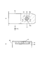
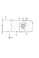
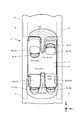
Classifications
-
- B—PERFORMING OPERATIONS; TRANSPORTING
- B60—VEHICLES IN GENERAL
- B60J—WINDOWS, WINDSCREENS, NON-FIXED ROOFS, DOORS, OR SIMILAR DEVICES FOR VEHICLES; REMOVABLE EXTERNAL PROTECTIVE COVERINGS SPECIALLY ADAPTED FOR VEHICLES
- B60J3/00—Antiglare equipment associated with windows or windscreens; Sun visors for vehicles
- B60J3/02—Antiglare equipment associated with windows or windscreens; Sun visors for vehicles adjustable in position
-
- B—PERFORMING OPERATIONS; TRANSPORTING
- B60—VEHICLES IN GENERAL
- B60N—SEATS SPECIALLY ADAPTED FOR VEHICLES; VEHICLE PASSENGER ACCOMMODATION NOT OTHERWISE PROVIDED FOR
- B60N2/00—Seats specially adapted for vehicles; Arrangement or mounting of seats in vehicles
- B60N2/02—Seats specially adapted for vehicles; Arrangement or mounting of seats in vehicles the seat or part thereof being movable, e.g. adjustable
- B60N2/04—Seats specially adapted for vehicles; Arrangement or mounting of seats in vehicles the seat or part thereof being movable, e.g. adjustable the whole seat being movable
- B60N2/14—Seats specially adapted for vehicles; Arrangement or mounting of seats in vehicles the seat or part thereof being movable, e.g. adjustable the whole seat being movable rotatable, e.g. to permit easy access
- B60N2/143—Seats specially adapted for vehicles; Arrangement or mounting of seats in vehicles the seat or part thereof being movable, e.g. adjustable the whole seat being movable rotatable, e.g. to permit easy access taking a position opposite to the original one
-
- B—PERFORMING OPERATIONS; TRANSPORTING
- B60—VEHICLES IN GENERAL
- B60N—SEATS SPECIALLY ADAPTED FOR VEHICLES; VEHICLE PASSENGER ACCOMMODATION NOT OTHERWISE PROVIDED FOR
- B60N2/00—Seats specially adapted for vehicles; Arrangement or mounting of seats in vehicles
- B60N2/02—Seats specially adapted for vehicles; Arrangement or mounting of seats in vehicles the seat or part thereof being movable, e.g. adjustable
- B60N2/22—Seats specially adapted for vehicles; Arrangement or mounting of seats in vehicles the seat or part thereof being movable, e.g. adjustable the back-rest being adjustable
-
- B—PERFORMING OPERATIONS; TRANSPORTING
- B60—VEHICLES IN GENERAL
- B60N—SEATS SPECIALLY ADAPTED FOR VEHICLES; VEHICLE PASSENGER ACCOMMODATION NOT OTHERWISE PROVIDED FOR
- B60N3/00—Arrangements or adaptations of other passenger fittings, not otherwise provided for
-
- B—PERFORMING OPERATIONS; TRANSPORTING
- B60—VEHICLES IN GENERAL
- B60R—VEHICLES, VEHICLE FITTINGS, OR VEHICLE PARTS, NOT OTHERWISE PROVIDED FOR
- B60R11/00—Arrangements for holding or mounting articles, not otherwise provided for
- B60R11/02—Arrangements for holding or mounting articles, not otherwise provided for for radio sets, television sets, telephones, or the like; Arrangement of controls thereof
- B60R11/0229—Arrangements for holding or mounting articles, not otherwise provided for for radio sets, television sets, telephones, or the like; Arrangement of controls thereof for displays, e.g. cathodic tubes
- B60R11/0235—Arrangements for holding or mounting articles, not otherwise provided for for radio sets, television sets, telephones, or the like; Arrangement of controls thereof for displays, e.g. cathodic tubes of flat type, e.g. LCD
Definitions
- the present disclosure relates to an autonomously drivable vehicle.
- NHTSA National Highway Traffic Safety Administration
- SAE Society of Automotive Engineers
- the human driver does everything.
- a vehicle automation system can sometimes assist human drivers and perform some driving tasks.
- the vehicle's automation system can virtually perform some driving tasks, while human drivers monitor the driving environment and continue to carry out the remaining driving tasks. become.
- the automation system virtually performs some driving tasks and monitors the driving environment, if any, while the human driver prepares to regain control if the automation system requests it. It must be kept.
- the automation system can perform operating tasks and monitor the operating environment. Humans do not have to regain control, but automated systems can only operate in certain circumstances.
- the automation system can perform all driving tasks under all conditions that a human driver can drive.
- Level 4 is autonomous driving in a dedicated space or a limited area
- level 5 is autonomous driving without area limitation.
- Level 1 has been widely put to practical use
- Level 2 has been partially put to practical use.
- Level 3 while the autonomous driving system leads the driving, the driving by the human is requested as needed.
- Levels 1-3 require an interface between the autonomous driving system and the driver within the vehicle.
- the main notification from the autonomous driving system to the driver is to show the driver the behavior of the vehicle determined by the autonomous driving system.
- the driver can prepare for the next action of the vehicle based on the presented action.
- a notification is required to request the driver to switch from driving driven by the autonomous driving system to driving driven by the driver.
- Non-Patent Document 1 Non-Patent Document 1
- Patent Document 2 A seat rotation mechanism
- the present disclosure provides a vehicle capable of performing various activities while the vehicle occupant travels.
- a vehicle according to the present disclosure includes a vehicle body having a cabin, at least one wheel disposed on the vehicle body along a predetermined one direction, a seat disposed inside the cabin, and the vehicle body.
- a first planar member disposed on the outer side of the seat in the predetermined one direction and having a first transmittance for visible light, the first planar member, and the first planar member.
- a vehicle comprising: a second planar member which can be disposed between the seat and the second planar member having a second transmittance smaller than the first transmittance for visible light; and an input unit, wherein the input unit When there is a predetermined input, the second planar member is disposed between the first planar member and the seat.
- the vehicle of the present disclosure includes at least one rotatable wheel, a first seat on which a first passenger can sit, a second seat on which a second passenger can sit, and at least a periphery of the first seat.
- the vehicle according to the present disclosure is disposed along at least one of a rotatable wheel, a seat on which a passenger can be seated, and at least a part of a periphery of the seat, along the traveling direction of the wheel.
- the seat is rotatable about a direction perpendicular to a plane formed by the traveling direction of the wheel and the rotational axis direction of the wheel, and the armrest portion is rotated along with the rotation of the seat. It does not move, and the touch panel portion is disposed at a position away from the position of the rotation axis of the seat in the traveling direction inside the armrest portion.
- the vehicle of the present disclosure is disposed along at least one of rotatable wheels, at least one seat on which a passenger can sit, and at least a part of the periphery of the seat, along the traveling direction of the wheels.
- a touch panel portion disposed in an overlapping manner, and a cover portion disposed in an overlapping manner on the light emitting portion and the touch panel portion, having a predetermined transmittance for the predetermined light, and covering at least a part of the armrest portion
- the touch panel unit is a vehicle capable of detecting a position along a predetermined plane including the traveling direction of the wheel and the rotation axis direction of the wheel with respect to a finger of the passenger.
- Bar portion covers the entire surface of the light emitting portion and the touch panel unit, covers at least 50% of the upper surface of
- the second planar member having a transmittance smaller than that of the first planar member is disposed between the first planar member and the seat, visible light passing through the first planar member is blocked.
- the intensity of light from the outside of the vehicle body such as sunlight is alleviated, and the environment around the second planar member becomes calm.
- the opposing passengers can input various items of the vehicle. Comfort in the living mode is improved.
- the touch panel unit is disposed at a position away from the position of the rotation axis of the seat in the traveling direction inside the armrest unit, the passenger performs various operations on the vehicle even if the seat rotates. It is possible.
- the cover portion covers the entire surface of the light emitting portion and the touch panel portion and covers at least 50% of the upper surface of the armrest portion, so that a sense of unity in design is improved.
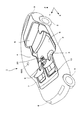
- FIG. 1 is a perspective view of a vehicle according to the present disclosure.
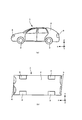
- FIG. 2 shows a vehicle according to the present disclosure, and (a) a side view, (b) a schematic view showing a positional relationship of wheels.
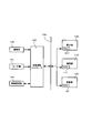
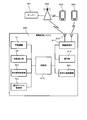
- FIG. 3 is a block diagram of a vehicle according to the present disclosure.
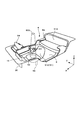
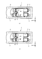
- FIG. 4 is a schematic view showing an arrangement of a passenger compartment in a living mode according to the present disclosure.
- FIG. 5 is a schematic view showing an arrangement in a passenger compartment in a business mode according to the present disclosure.
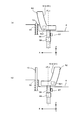
- FIG. 6 is a conceptual diagram showing an embodiment of a rotation mechanism in a vehicle seat, (a) living mode, (b) business mode.
- FIG. 7 is a conceptual view showing another embodiment of the seat rotation mechanism in the vehicle, (a) living mode, (b) business mode.
- FIG. 8 is a schematic view showing the arrangement of each seat in the vehicle, (a) living mode, (b) business mode.
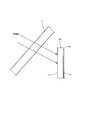
- FIG. 9 is a schematic view showing a visible light transmission relationship between the first planar member and the second planar member according to the present disclosure.
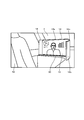
- FIG. 10 is a schematic view showing an embodiment of the use of the second planar member according to the present disclosure.
- FIG. 11 is a schematic view showing an embodiment of a movable mechanism of a second planar member according to the present disclosure.
- FIG. 12 is a block diagram showing an embodiment of a drive control system for controlling the movement of the second planar member and the rotation of the seat according to the present disclosure.
- FIG. 13 is a conceptual view showing a relationship between a rotation detection unit and a second planar member according to the present disclosure.
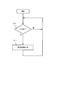
- FIG. 14 is a flowchart showing operation steps of the second planar member according to the present disclosure.
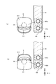
- FIG. 15 is a partial cross-sectional view showing another embodiment of the first planar member according to the present disclosure.
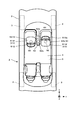
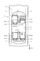
- FIG. 16 is a plan view of a passenger compartment of a vehicle according to the present disclosure.
- FIG. 17 is a partial perspective view of the vehicle interior of FIG. 16;
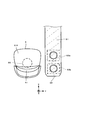
- FIG. 18 is a schematic view showing an armrest part, a cover part, a touch panel part and a light emitting part of the present disclosure, (a) top view, and (b) a sectional view taken along line AA of (a).
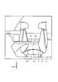
- FIG. 19 is a partial perspective view of the vehicle interior of FIG. 16;
- Drawing 20 is a mimetic diagram showing one embodiment of a touch panel part of this indication, (a) Main switch OFF state, (b) Main switch ON state.
- FIG. 21 is a schematic view showing an example of an item of a vehicle of the present disclosure.
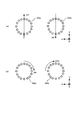
- FIG. 22 is a schematic view showing the operation direction of the touch panel portion of the present invention, (a) operation direction 1, (b) operation direction 2, (c) operation direction 3.
- FIG. 23: is a schematic diagram following FIG. 22, (a) operation direction 4, (b) operation direction 5.
- FIG. FIG. 24 is a plan view of a passenger compartment of a vehicle according to another embodiment.
- FIG. 25 is a conceptual diagram for explaining another example of a seat rotation mechanism according to another embodiment.
- FIG. 26 is a schematic view showing an example of a seat and a touch panel unit according to another embodiment.
- FIG. 27 is a schematic view showing a relationship between a seat and a touch panel in FIG.
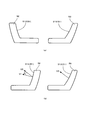
- FIG. 28 is a plan view of a vehicle interior for explaining the rotation angle of a seat according to another embodiment, (a) rotation angle of 90 degrees to 180 degrees, (b) rotation angle of 180 degrees.
- FIG. 29 is a schematic view showing an example of a hollow portion of an armrest according to another embodiment.
- FIG. 30 is a plan view of a passenger compartment of a vehicle according to another embodiment.
- FIG. 31 is a schematic view showing a state in which the area of a cover according to another embodiment is 50%, (a) a top view, and (b) an AA sectional view of (a).
- FIG. 32 is a schematic view showing a state in which the area of a cover according to another embodiment is 80%.
- FIG. 33 is a plan view of a passenger compartment of a vehicle showing
- the embodiment which specifically discloses a vehicle according to the present disclosure will be described in detail with reference to the drawings as appropriate.
- the detailed description may be omitted if necessary.
- detailed description of already well-known matters and redundant description of substantially the same configuration may be omitted. This is to avoid unnecessary redundancy in the following description and to facilitate understanding by those skilled in the art.
- the attached drawings and the following description are provided to enable those skilled in the art to fully understand the present disclosure, and they are not intended to limit the claimed subject matter.
- FIGS. 1 to 8 show configurations common to the present embodiment
- FIGS. 30 to 33 show an embodiment in which the cover portion is described in detail.
- FIG. 1 is a perspective view showing a vehicle 1 of the present embodiment.
- the embodiment of the vehicle 1 exemplifies an automobile capable of automatically traveling in an automobile based on the Road Transportation Vehicle Law.
- the vehicle 1 is capable of autonomous traveling (automatic driving), and in the present invention, a traveling direction such as forward, backward, left-right turn, rotation, etc. is defined as “predetermined one direction”.
- a predetermined one direction is the X direction
- the Y direction is perpendicular to the X direction in the width direction of the vehicle 1
- the Z direction is perpendicular to the X direction in the height direction of the vehicle 1.
- the X direction may be the front-rear direction including not only the front but also the rear with respect to the vehicle 1.
- the vehicle 1 has a vehicle body 2 and wheels 3 constituting the vehicle 1, and a compartment 4 defined by the vehicle body 2, a plurality of seats 5 disposed in the compartment 4, and a part of the compartment 4 And a first planar member 7 such as a windshield, and a plurality of lights 8 and 9 such as headlights necessary for safe traveling.
- first planar member 7 is disposed outside the seat 5 in a predetermined one direction (X direction) to separate the room 4 from the outside of the vehicle.
- the second planar member 10 which can move up and down is disposed between the first planar member 7 and the seat 5 in the compartment 4 in the vicinity of the first planar member 7, and the first planar member 7.
- the second planar member 10 has a second transmittance for visible light that is smaller than the first transmittance.
- an input unit 20 operable by the passenger is disposed in the passenger compartment 4, and the passenger needs to be in the passenger compartment 4 such as rotation of the seat 5, operation of the second planar member 10, wireless communication, etc. Information can be accepted.
- the vehicle 1 is provided with a specific light 8 for illuminating the inside and outside of the vehicle and a plurality of other lights 9.
- the illumination 8 illuminates a predetermined one direction outside the vehicle and is, for example, a headlight capable of illuminating a stronger light than each of the other illuminations 9.
- the plurality of lights 9 include, for example, fog lights, side lights, turn signal lights, tail lights, stop lights, room lights and the like other than headlights.
- the other lights 9 in the embodiment show tail lights, but may be other lights such as turn signal lights.
- FIG. 2 shows the vehicle 1, (a) is a side view, and (b) is a schematic view showing the positional relationship of the wheels 3.
- the vehicle 1 can travel by rotating the wheels 3, and each wheel 3 can move or be fixed for steering, and can travel forward, backward, turn left, turn, or the like.
- the vehicle 1 according to the present embodiment is described by taking a general four-wheeled passenger car as an example, but the present invention is not limited to the size, the shape, the number of seats, the number of wheels, and the like.
- FIG. 3 is a block diagram of the vehicle 1 according to the present embodiment.
- the vehicle 1 according to the present embodiment is a vehicle with an automatic driving level 1 or higher, and in the following description, a vehicle with a level 3 or higher is assumed.
- the vehicle 1 includes a power unit 100, a steering unit 110, a braking unit 120, an automatic driving controller 130, an imaging unit 140, a sensor unit 141, a wireless communication unit 142, and an in-vehicle network 150 with a gateway function.
- the power unit 100 is a generic name of members for accelerating the vehicle 1 and includes an engine and / or a traveling motor, a transmission, a power system ECU (Electronic Control Unit) 101 and the like.
- the steering unit 110 is a generic term for a member for curving the vehicle 1 and includes power steering, steering system ECU 111 and the like.
- the braking unit 120 is a generic term for members for decelerating and stopping the vehicle 1 and includes a brake (hydraulic brake / regenerative brake / regenerative coordinated brake), an ABS (Antilock Brake System), a braking system ECU 121 and the like.
- the power system ECU 101, the steering system ECU 111, and the braking system ECU 121 are connected to the in-vehicle network 150, respectively.
- the in-vehicle network 150 is constructed using at least one of standards such as CAN (Controller Area Network), LIN (Local Interconnect Network), FlexRay (registered trademark), Ethernet (registered trademark), and the like.
- the power system ECU 101, the steering system ECU 111, and the braking system ECU 121 are connected to the main network of the in-vehicle network 150.
- the main network uses CAN.
- the operation information of the vehicle 1 converts the driver's operation on the accelerator pedal or the like into an electrical control signal, and transmits it to the power system ECU 101, the steering system ECU 111, or the braking system ECU 121 via the in-vehicle network 150.
- the power system ECU 101, the steering system ECU 111, or the braking system ECU 121 controls the corresponding actuator based on the received control signal.
- the imaging unit 140 is a generic name of at least one or more cameras installed in the vehicle 1. For example, visible light cameras are installed at four places in front of, behind, and left and right of the vehicle 1 as the imaging unit 140, and images of the front, back, and left and right of the vehicle 1 are photographed with four visible light cameras.
- the imaging unit 140 outputs the generated image signal obtained by photoelectric conversion to the automatic driving controller 130. Not only visible light but also infrared light detection camera can be used to make night travel more safely.
- the sensor unit 141 is a generic name of various sensors (except for the imaging unit 140) for grasping the state of the vehicle and the situation around the vehicle.
- the sensor unit 141 includes LIDAR (Light Detection and Ranging), a millimeter wave radar, a vehicle speed sensor, and a GPS sensor.
- the LIDAR emits a light beam (for example, an infrared laser) around the vehicle 1 and receives its reflected signal, and the distance from the object present around it based on the received reflected signal, the size of the object And measure the composition of the object.
- the millimeter wave radar emits radio waves (millimeter waves) around the vehicle 1, receives its reflected signal, and measures the distance to an object present in the surroundings based on the received reflected signal. Millimeter-wave radar can also detect distant objects that are difficult to detect with LIDAR.
- the vehicle speed sensor detects the speed of the vehicle 1.
- the GPS sensor detects position information of the vehicle 1. Specifically, the transmission time is received from each of a plurality of GPS satellites, and the latitude and longitude of the reception point are calculated based on the plurality of received transmission times.
- the wireless communication unit 142 performs wireless communication with an external data center, a roadside device, another vehicle, and the like. For example, using a cellular phone network (cellular network), wireless LAN, ETC (Electronic Toll Collection System), DSRC (Dedicated Short Range Communications), V2I (Vehicle-to-Infrastructure), V2V (Vehicle-to-Vehicle). Can.
- cellular phone network cellular network
- wireless LAN wireless LAN
- ETC Electronic Toll Collection System
- DSRC Dedicated Short Range Communications
- V2I Vehicle-to-Infrastructure
- V2V Vehicle-to-Vehicle
- the autonomous driving controller 130 holds data necessary for autonomous traveling, such as a three-dimensional map, and autonomously travels the vehicle 1 based on a predetermined autonomous driving algorithm. Specifically, based on the image data generated by the imaging unit 140, the various detection data detected by the sensor unit 141, and the various information collected from the outside via the wireless communication unit 142, the automatic driving controller 130 performs its own operation. Recognize the condition of the car and the circumstances around the car.
- the autonomous driving controller 130 applies various parameters indicating the recognized state of the vehicle and the situation around the vehicle to the autonomous driving algorithm to determine the action of the vehicle 1.
- the autonomous driving controller 130 generates a control command based on the determined action, and transmits the control command to the power system ECU 101, the steering system ECU 111, or the braking system ECU 121 via the in-vehicle network 150.
- the power system ECU 101, the steering system ECU 111, or the braking system ECU 121 controls the corresponding actuator based on the received control command.
- the autonomous driving algorithm is generated by artificial intelligence (AI) based on deep learning, for example.
- AI artificial intelligence
- Various parameters of the autonomous driving algorithm are initially set to values learned by a high-spec computer in advance, and values updated from the data center on the cloud are downloaded as appropriate.
- connection form of the in-vehicle network 150 shown in FIG. 3 is an example, and various connection forms can be used.
- the imaging unit 140, the sensor unit 141, and the wireless communication unit 142 are connected to the automatic driving controller 130 via the main network, but the imaging unit 140, the sensor unit 141, and the wireless communication unit 142 May be directly connected.
- the automatic driving controller 130, the power system ECU 101, the steering system ECU 111, the braking system ECU 121, and the in-vehicle network 150 are generated based on the ASIL of the ISO26262 standard.
- an instrument panel including a speedometer, a tachometer, etc. is also generated in accordance with the ASIL of ISO26262 standard.
- the information related to the autonomous traveling includes the behavior of the vehicle 1 determined by the autonomous driving controller 130.
- the autonomous driving controller 130 may basically display the current action (for example, acceleration, deceleration, right curve, left curve) of the vehicle 1 on a display unit (not shown) or the like. Further, the autonomous driving controller 130 may display the next action of the vehicle 1 determined based on the autonomous driving algorithm from a predetermined time before the scheduled time for executing the action.
- the autonomous driving controller 130 may determine that autonomous traveling is difficult. For example, it may be difficult to identify a lane on a road where no dividing line is drawn on the road surface, which may make autonomous traveling difficult. Further, in the case of thick fog or heavy rain, it may be difficult to capture the front of the vehicle 1 clearly and autonomous traveling may be difficult.
- the autonomous driving controller 130 may request the driver to switch from driving driven by the autonomous driving controller 130 to driving driven by the driver.
- FIG. 4 is a schematic view showing the arrangement in the passenger compartment 4 in the living mode.
- FIG. 5 is a schematic view showing the arrangement in the passenger compartment 4 in the business mode. The living mode and the business mode according to the present embodiment will be described with reference to FIGS. 4 and 5.
- the “living mode” refers to a state in which the passengers face each other and can chat during automatic driving
- the “business mode” means that the seat 5 faces forward as usual. It refers to the situation where one can concentrate on work etc.
- the seat 5 is made rotatable, and the second planar member 10 is made movable up and down. The seat 5 will be described in detail with reference to FIGS. 6 and 7 as well.
- Each seat 5 has a backrest 51 and is divided into a first seat 52, a second seat 53 and a third seat 54. Further, the first seat 52, the second seat 53 and the third seat 54 are arranged along a predetermined one direction of the vehicle 1. The first seat 52 and the third seat 54 are disposed along a direction orthogonal to a predetermined one direction. The “direction orthogonal to the predetermined one direction” is a direction orthogonal to the predetermined one direction and along the floor surface 6.
- the first seat 52 is described as a driver's seat, the second seat 53 as a rear seat, and the third seat as a passenger seat.
- the first seat 52 includes a rotating shaft 55.
- the first seat 52 can rotate around the rotating shaft 55 to select the living mode position and the business mode position.
- a passenger (driver) sitting on the first seat 52 and a passenger sitting on the second seat 53 (the backrest 512 of the first seat 52 and the backrest 513 of the second seat 53 face each other) It becomes a living mode in which a passenger can face, a face-to-face conversation between the passengers is possible, and a meeting can be made (see FIG. 4).
- the third seat 54 may also be pivotable with the pivot 55, allowing automatic or manual rotation of the third seat 54. It is not necessary to face the passengers of the first seat 52 and the passengers of the second seat 53 directly in front of each other if the backrest 512 and the backrest 513 face each other to the extent that they can talk and meet. good.
- in-ceiling light 600 capable of illuminating at least the first seat 52 and illuminating the first seat 52 is disposed on the ceiling of the cabin 4 and the like, and in reading mode, in a business mode, etc. It can be used as lighting for the occasion.
- FIG. 6 is a conceptual diagram for explaining an embodiment of the rotation mechanism including the rotation shaft 55.
- the rotating shaft 55 is vertical with respect to the floor surface 6 and supported by the bearing 56 and can be rotated by driving an actuator such as a motor (not shown).
- the movement of the rotation shaft 55 is detected by the rotation detection unit 57.
- FIG. 6 (a) shows the living mode
- FIG. 6 (b) shows the business mode.
- the rotation of the first seat 52 is also possible manually.
- the rotation mechanism is a belt type, a gear type, a crank type, or the like, and is not limited to the present embodiment.
- a disk fixed to the seat 5 may be rotated by meshing of gears, etc., and the present invention is not limited to this embodiment.
- the rotation of the first seat 52 can be selected from automatic rotation or manual rotation by the rider unlocking.
- the first seat 52 has a reclining function, and the backrest 512 can be rotated in its movable range A by driving the backrest control mechanism 521, and the inclination angle of the backrest 512 can be changed. .
- the backrest 512 of the first seat 52 and the backrest 513 of the second seat 53 face in the same direction, and the business mode is set. (See Figure 5). That is, from the arrangement relationship between the first seat 52 and the second seat 53 in the living mode, the first seat 52 is rotated, and the occupant of the first seat 52 is arranged to face forward.
- FIG. 7 is a conceptual diagram for explaining another embodiment of the rotation mechanism including the rotation shaft 55, and FIG. 7 (a) shows a living mode time, and FIG. 7 (b) shows a business mode time.
- the first seat 52 is disposed closer to the second planar member 10 as compared to the embodiment of FIG. Therefore, when at least the backrest 512 of the first seat 52 and the backrest 513 of the second seat 53 are in the opposite state, the first seat 52 of the first seat 52 in a direction perpendicular to the floor 6 of the passenger compartment 4.
- the backrest 512 and the second planar member 10 are disposed in an overlapping manner.
- the second planar member 10 is controlled by controlling at least a part of the second planar member 10 to be stored in the storage unit 30 regardless of whether or not the backrest 512 is reclining. Interference with the backrest 512 can be prevented. Such control may be performed in the embodiment of FIG.
- FIG. 8 is a schematic view showing the arrangement of the seats 5, where (a) is a living mode and (b) is a business mode.
- the living mode the backrest 512 of the first seat 52 and the backrest 513 of the second seat 53 face each other, and in the business mode, the backrest 512 of the first seat 52 and the back 513 of the second seat 53 are identical. It is facing in the direction.
- an angle ⁇ between the vertical vector V1 of the backrest 512 of the first seat 52 and the vertical vector V2 of the backrest 513 of the second seat 53 is, for example, 0 ° to 20 °, 0 ° to Ranges of 30 °, 0 ° -40 °, 0 ° -60 °, 0 ° -89 ° etc. are acceptable.
- the range of motion of the backrest 512 of the first seat 52 is limited. Can be limited.
- the second planar member 10 can be controlled so as not to be disposed between the first planar member 7 and the first seat 52. Such control can prevent interference between the second planar member 10 and the backrest 512 in the living mode.
- the second planar member 10 ascends from the storage unit 30 and is exposed in the compartment 4, and is disposed between the first planar member 7 and the first seat 52.
- the second planar member 10 has a second transmittance smaller than the first transmittance of the first planar member 7, and visible light transmitted through the first planar member 7 is shown in FIG. 9. Light is blocked by the first surface 11 of the second planar member 10 (see the arrow in FIG. 9).
- the second transmittance may be zero.
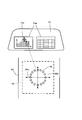
- a rectangular display unit 13 or the like is provided on the second surface 12 on the side of the first seat 52 not facing the first planar member 7 of the second planar member 10.
- the long side direction of the display unit 13 may be orthogonal to a predetermined one direction. When arranged in the direction orthogonal to the predetermined one direction, the occupant of the first seat 52 can easily view and work.
- the display unit 13 may be square, oval, or the like, and is not limited to a rectangle.
- a plurality of screens may be arranged, and a plurality of screen divisions may be possible.
- the passenger sitting in the first seat 52 can, for example, perform a video conference as shown in FIG. 10 through the display unit 13.
- the display unit 13 is a display device such as a liquid crystal panel or an organic EL panel, and may be a UI (user interface) type touch panel that performs various processes by contacting a finger or a pen, and performs information input and various operations.
- a screen etc. can be displayed.
- a screen for a projector or the like may be used.
- the visible light is blocked by the second planar member 10, making it difficult to see the scenery outside the vehicle 1. It becomes possible to interrupt bothersome light such as sunlight and street light, and it becomes easy to be engrossed in work.
- the display contents of the display unit 13 can be easily viewed, and the environment of the business mode is improved.
- FIG. 11 is a schematic view showing an example of the movable mechanism 14 of the second planar member 10. The operation of the movable mechanism 14 will be described with reference to FIG.
- the movable mechanism 14 in the present embodiment includes a motor 15, a first screw portion 16, a second screw portion 17, a rail 18, and a sensor portion 19.
- the first screw portion 16 is rotated by the drive of the motor 15, and the second screw portion 17 screwed to the first screw portion 16 is moved up and down, fixed to the second screw portion 17 and supported by the rail 18
- the second planar member 10 ascends and descends.
- the elevating state is detected by the sensor unit 19.
- the second planar member 10 in the living mode, the second planar member 10 is lowered and stored in the storage unit 30.
- the second planar member 10 In the business mode, the second planar member 10 is raised and exposed (stands up) from the storage unit 30, It is disposed between the first planar member 7 and the first seat 52.
- the second planar member 10 can rise over a movable range B indicated by a broken line.
- the second planar member 10 has a substantially L-shaped cross section, and on the second surface 12 side, the front surface portion 12a opposite to the backrest 512 of the first seat 52, and the front surface portion 12a It has a side portion 12 b extending laterally to one seat 52.
- the display unit 13 is disposed on the front unit 12 a, and the side unit 12 b is disposed between the first seat 52 and the third seat 54.
- the front surface portion 12a and the side surface portion 12b may be connected by a curved surface 12c, and the second planar member 10 may partially have a curved surface.
- the side surface portion 12b may be provided on both sides of the front surface portion 12a, and it is easy to shield the landscape and light from the side glass as well as the separation from the third seat 54.
- FIG. 12 shows the light control device 7a of the first planar member (see FIG. 15), the movement of the second planar member 10, the rotation of the seat 5, the movable range A of the backrest 512 of the first seat 52, and the in-vehicle lighting 600.
- FIG. 6 is a block diagram illustrating an embodiment of a drive control system that controls the drive control system. The drive control system of the present embodiment will be described with reference to FIG.
- the drive control system 200 controls the dimmer device 7a of the first planar member, the movement of the second planar member 10, the rotation of the seat 5, the movable range A of the backrest of the first seat 52, and the in-vehicle lighting 600.
- An optical device control unit 701 is provided.
- the control unit 210 receives a detection signal of the rotation detection unit 57 that detects the rotation of the first seat 52, and the control unit 210 instructs the movable mechanism 14 to start moving, and the movable mechanism 14 generates the second motion based on the command.
- the two-sided member 10 is moved up and down.
- control unit 210 instructs the light control device control unit 701 capable of directly controlling the light control device 7a of the first planar member to move the liquid crystal 7b of the light control device 7a ( Drive (see FIG. 15) to change the transmittance.
- control unit 210 instructs the backrest control mechanism 521 to change the movable range A of the backrest of the first seat 52, and further instructs the in-vehicle lighting control unit 601 to change the illuminance of the in-vehicle lighting 600. . Only some of these can be implemented.
- the wireless communication unit 211 can communicate with an external base station 300, a server 301, various terminals 302 such as a smart phone, a key, a mobile phone, a PC, and the like via the antenna unit 213.
- the operation unit 212 is, for example, switches operated by a passenger of the input unit 20 disposed in the passenger compartment 4, and can receive the operation of the passenger. Rotation and elevation of the second planar member 10 can be performed.
- the operation of the seat 5 and the second planar member 10 can also be performed from the server 301, the terminal 302, and the like. Communication can be received from the various terminals 302 and servers 301 via the cell station etc. via the base station 300, and when performing direct communication with the terminal 302, use near field communication (for example, Bluetooth (registered trademark)) etc. Can.
- near field communication for example, Bluetooth (registered trademark)
- the input unit 20 can include, in addition to the operation unit 212 described above, a wireless communication unit 211 that receives an input operation, a rotation detection unit 57 that detects the rotation of the seat 5, and the like.
- FIG. 13 is a conceptual view showing the relationship between the rotation detection unit 57 and the second planar member 10. As shown in FIG. The operation relationship between the rotation detection unit 57 and the second planar member 10 will be described with reference to FIG.
- the control unit 210 Ascending of the second planar member 10 is instructed to the movable mechanism 14, the movable mechanism 14 is movable, and the second planar member 10 is exposed from the storage portion 30. Further, the control unit 210 instructs the light adjustment device control unit 701 capable of directly controlling the light adjustment device 7a of the first planar member to drive the liquid crystal 7b of the light adjustment device 7a to control the transmittance (described later) Specifically to lower).
- control unit 210 instructs the in-vehicle illumination control unit 601 to change the illuminance of the in-vehicle illumination 600. Further, the control unit 210 instructs the backrest control mechanism 521 to limit the backrest movable range A of the first seat 52 (S2).
- the control unit 210 instructs the movable mechanism 14 to lower the second planar member 10, and the movable mechanism 14 moves so as to store the second planar member 10 in the storage unit 30. Further, the control unit 210 instructs the light control device control unit 701 capable of directly controlling the light control device 7a of the first planar member to drive the liquid crystal 7b of the light control device 7a to return the transmittance. The control unit 210 also instructs the in-vehicle lighting control unit 601 to return the illuminance of the in-vehicle lighting 600. Further, the control unit 210 instructs the backrest control mechanism 521 to release the restriction of the backrest movable range A of the first seat 52 (S4).
- the in-vehicle lighting control unit 601 increases the illuminance of the in-vehicle lighting 600 when the second planar member 10 is disposed between the first planar member 7 and the first seat 52. Control. This makes the work environment in the business mode more comfortable. In addition, since the area of the seat other than the first seat 52 becomes relatively dark, it is possible to protect the privacy of other passengers. Furthermore, in a situation such as a teleconference shown in FIG. 10 in which dialogue with the other party occurs, the other party (for example, the person displayed on the display unit 13) can easily concentrate on the dialogue and the environment in which the dialogue is more easily performed. Provided.
- the movable mechanism 14 operates based on a command from the control unit 210, and the second surface It will be in the predetermined
- the in-vehicle lighting control unit 601 increases the illuminance of the in-vehicle lighting 600 to make the in-vehicle lighting 600 the first seating surface of the first seat 52 a first brightness.
- the in-vehicle lighting control unit 601 lowers the illuminance of the in-vehicle lighting 600 to make the in-vehicle lighting 600 the first brightness mentioned above for the seating surface of the first seat 52.
- the second brightness is darker than
- the movable area A of the backrest 512 and the movable area B of the second planar member 10 may overlap, and depending on the angle of rotation of the first seat 52, the backrest 512 and Interference of the second planar member 10 may occur. Such interference may occur at the transition between the business mode and the living mode.
- the backrest control mechanism 521 is a state in which the first seat 52 and the second seat 53 face in the same direction as the facing state (FIGS. 6A and 8A) based on the command of the control unit 210.
- the range of motion A of the backrest 512 of the first seat 52 is limited.
- the angle of the movable range A may be reduced, or the angle may be zero. Since such limitation is possible, interference between the backrest 512 and the second planar member 10 is prevented even if the first seat 52 rotates regardless of the position of the second planar member 10.
- the reclining movable range A of the backrest 512 and the movable range B of the second planar member are allowed to overlap. That is, the first seat 52 to be reclined can be installed close to the second planar member 10, which is advantageous for utilizing the space inside the vehicle. Further, the movable area A of the backrest 512 is limited until storage of the second planar member 10 is completed, that is, in the exposed state of the second planar member 10 so that the second planar member 10 and the backrest 512 do not interfere with each other. Can be controlled as well.
- rotation of the 1st seat 52 can also be performed by input operation with respect to the input part 20, and can also be performed manually. Also, there may be a threshold detected by the rotation detection unit 57, and the control unit 210 can also move the second planar member 10 by detecting the predetermined angle and rotation and instructing the movable mechanism 14 to move. .
- control unit 210 may control so as to put the second planar member 10 in the storage state (see FIG. 6A). Thereby, the interference between the first seat 52 and the second planar member 10 can be prevented without restricting the movable range A of the backrest 512.
- FIG. 14 is a flowchart showing the operation steps of the second planar member 10.
- the control unit 210 determines whether there is an input signal at the input unit 20 (S10).
- the input signal is transmitted from the operation unit 212 such as a switch, the wireless communication unit 211 that receives an input operation by the terminal 302 or the like, the rotation detection unit 57 that detects the rotation of the seat 5 or the like.
- the control unit 210 drives the movable mechanism 14 to raise the second planar member 10 (S11). The same applies to the case where the second planar member 10 is lowered.
- FIG. 15 is a partial cross-sectional view showing another embodiment of the first planar member 7.
- the first planar member 7 is provided with a light control device 7 a for changing the transmittance.
- the light control device 7a may be attached to the second planar member 10 or may be integrally formed.
- the light control device 7a of the present embodiment has a structure in which the liquid crystal 7b is sandwiched between two glass plates 7c.
- the transmittance can be changed by the light control device 7a, and the working environment can be improved by linking with the business mode.
- Japanese Patent Application Laid-Open No. 2016-69533 which is a family gazette
- US application publication 2017/0307915 for the light control device.
- the first transmittance of the first planar member 7 can be changed in two or more steps, and the second planar member 10 can be formed by the first planar member 7 and the first planar member 7.
- the first transmittance of the first planar member 7 can be changed in two or more steps, and the second planar member 10 can be formed by the first planar member 7 and the first planar member 7.
- an input unit 20 operable by a passenger is disposed in the passenger compartment 4, and the passenger rotates the seat 5, operates the second planar member 10, wireless communication, etc.
- the arrangement of the input unit 20 is omitted based on FIGS. 16 to 18 and the armrest unit adjacent to the seat and the cover unit provided on the armrest unit, the touch panel unit, and the light emitting unit will be described in detail.
- the traveling direction is defined as “predetermined one direction”, and in the drawing, the predetermined one direction is the X direction, the Y direction is perpendicular to the X direction in the width direction of the vehicle 1, and the Z direction is It has been described that the height direction of the vehicle 1 is perpendicular to the X direction.
- predetermined one direction is further defined as “traveling direction of the wheel 3”
- width direction (Y direction) of the vehicle 1 orthogonal to the traveling direction of the wheel 3 is defined as “rotational axis direction of the wheel 3”.
- the backrest 512 of the first seat 52 and the backrest 513 of the second seat 53 face each other, and the passenger (driver) sitting on the first seat 52 and the second seat 53 sit It has been described that a living mode in which a passenger can meet, a face-to-face conversation between the passengers becomes possible, and a meeting or the like becomes possible. In addition, it has been described that the third seat 54 can also rotate to face the passenger of the second seat 53.
- the second seat 53 is defined as a second seat 53a, and the seat adjacent to the second seat 53a is defined as a fourth seat 53b.
- the first seat 52 can be seated by the first passenger
- the second seat 53a can be seated by the second passenger
- the third seat 54 can be seated by the third passenger
- the seat 53b is defined as a seat 5 on which the fourth passenger can sit.
- the first seat 52 and the second seat 53a, and the third seat 54 and the fourth seat 53b are disposed along the traveling direction (X direction) of the wheel 3, and the first seat 52, the third seat 54 and the second seat
- the seat 53 a and the fourth seat 53 b are disposed along the rotation axis direction (Y direction) of the wheel 3.
- an armrest portion 60 fixed to the vehicle 1 is disposed adjacent to the seat 5.
- the first armrest portion 60a is disposed along at least a part of the periphery of the first seat 52 along the traveling direction of the wheel 3 and can place at least a portion of the arm of the first passenger.
- the second armrest portion 60b is disposed along the traveling direction of the wheel 3 at least at a part of the periphery of the second seat 53a, and can place at least a part of the arm of the second passenger.
- at least a portion of the first armrest portion 60a is disposed between the first seat 52 and the third seat 54, and at least a portion of the second armrest portion 60b is configured with a second seat 53a and a fourth seat 53b. Is placed between.
- the armrest portion 60 is covered with a light transmitting cover portion 61, and is covered by the cover portion 61 so that a touch panel portion 62 disposed inside the armrest portion 60 and a light emitting portion 63 serving as a light source. And.
- the cover 61 partially or entirely covers the armrest 60, that is, at least a part of the armrest 60, has a predetermined transmittance for predetermined light such as visible light, and is made of a decorative cover or the like. For example, it is provided with a wood grain, carbon fiber tone, or it is made of a honjo (honmonaku). A portion of the cover 61 covered with at least a two-dot chain line has a pattern of wood grain or the like (common in all the drawings).
- the touch panel unit 62 is a UI (user interface) type that performs various processes by contacting a finger or a pen, and can display a screen or the like on which information input or various operations are performed.
- the light emitting unit 63 is a liquid crystal panel, an organic EL (Electro Luminescence), a micro LED (Light Emitting Diode), or the like, and can emit predetermined light such as visible light.
- the cover unit 61, the touch panel unit 62, and the light emitting unit 63 are arranged in an overlapping manner. In the present embodiment, the cover unit 61, the touch panel unit 62, and the light emitting unit 63 are arranged in the order of overlapping.
- first armrest portion 60a is provided with a first cover portion 61a, a first touch panel portion 62a and a first light emitting portion 63a
- second armrest portion 60b is also provided with a second cover portion 61b, A touch panel unit 62b and a second light emitting unit 63b are provided.
- the vehicle 1 further includes a display unit 70 that can be operated by the touch panel unit 62 and a sound emitting unit 71.
- the display unit 70 is disposed between the first seat 52 and the second seat 53a, and also disposed between the third seat 54 and the fourth seat 53b. Not only the first passenger and the second passenger, but all the passengers effectively including the third passenger sitting in the third seat 54 and the fourth passenger sitting in the fourth seat 53b. It is possible to browse content 70b and the like, which will be described later, of the display unit 70.
- the display unit 70 can effectively use the inside of the passenger compartment 4 by being disposed on the side surface, the ceiling, or the like of the passenger compartment (indoor) 4 of the vehicle 1.
- the sound emitting unit 71 is a speaker, and is disposed on the side surface of the vehicle compartment 4 between the first seat 52 and the second seat 53 similarly to the display unit 70, and can output audio content. .
- the sound emitting unit 71 may be disposed on the ceiling in the passenger compartment 4.
- the touch panel unit 62 is suitable for the living mode by allowing reception of input when the first backrest 512 of the first seat 52 and the second backrest 513a of the second seat 53a are disposed to face each other. It is possible to create an environment. Then, the first touch panel portion 62a can receive an input of at least an item of the vehicle 1, and the second touch panel portion 62b can receive an input of at least an item of the vehicle 1. As a result, the opposing passenger can perform various operations on the vehicle 1, and the comfort in the living mode is increased.
- the first backrest 512 of the first seat 52 and the second back 513a of the second seat 53a face each other, the first passenger of the first seat 52 and the second passenger of the second seat 53a face in front of each other It is not necessary, as long as they meet each other to the extent that they can talk and meet. Further, the facing of the third backrest 514 of the third seat 54 and the fourth backrest 513b of the fourth seat 53b is the same for the third passenger and the fourth passenger.
- Items of the vehicle 1 include the set temperature of air conditioning in the passenger compartment 4, music selection, output sound volume setting of audio equipment, operation of the pointer 70a of the display unit 70, and the like, corresponding to the display contents of the display unit 70. Information on the time of arrival at the destination, etc. are also included.
- the passenger can fast-forward the audio content by touching the mark 62f displayed on the touch panel 62, and can rewind the audio content by touching the mark 62g, and touch the mark 62h.
- the audio content can be stopped, played back, selected, and the like.
- a ring-shaped operable button 65 is displayed on the touch panel portion 62 as shown in FIG.
- the passenger can operate the button 65 using touch, drag, flick or the like.
- the button 65 has a number (including characters) 65a displayed at the center and an annular portion 65b formed of a plurality of segments so as to surround the number 65a.
- the numeral 65a representing the set temperature changes, for example, as 20, 21, 22 and can be set to the temperature desired by the passenger .
- the annular portion 65b is flicked clockwise, the temperature may be increased, and when it is counterclockwise, the temperature may be decreased.
- the button 65 displayed on the touch panel unit 62 has a two-dimensional coordinate axis corresponding to the display unit 70 in order to receive an input operation for an item of the vehicle 1.
- This coordinate axis may be displayed.
- the coordinate axis 65c of the arrow orthogonal to the center from the annular portion 65b is set, and the two-dimensional coordinate designated on the coordinate axis 65c is displayed on the display unit 70 as the pointer 70a.
- the item of the vehicle 1 is the two-dimensional coordinates of the display unit 70, and is scrolling of the content in the vertical direction and / or the horizontal direction.
- the touch panel unit 62 and the display unit 70 can be linked, and conversation, meetings, and the like can be performed in a comfortable environment.
- the content 70 b displayed on the display unit 70 may be information downloaded from a content server built on an external cloud via a communication network, or may be information downloaded from a portable terminal device carried by a passenger. By interlocking the display unit 70 and the button 65, various information can be displayed and operated.
- the direction in which the touch panel unit 62 is operated will be described based on FIGS. 22 and 23.
- the operation direction is indicated by an arrow on the drawing.
- the first backrest 512 of the first seat 52 and the second backrest 513a of the second seat 53a are disposed to face each other, the first passenger of the first seat 52, the second back of the second seat 53.
- the directions of the operations of the touch panel units of the passengers are as shown in FIGS. 22 and 23.
- the operation direction 1 shown in FIG. 22A the first input A1 in a predetermined direction along the traveling direction of the wheel 3 to the first touch panel portion 62a and the traveling direction of the wheel 3 to the second touch panel portion 62b And the second input A2 of the predetermined orientation along the same meaning. That is, the operation direction of the touch panel 62 is such that the first touch panel 62 a and the second touch panel 62 b are in the same direction along the traveling direction of the wheel 3.
- the fourth input A4 of the second orientation opposite to the first orientation along the same meaning is such that the operation direction of the touch panel 62 is such that the first touch panel 62 a and the second touch panel 62 b are in the opposite direction along the traveling direction of the wheel 3.
- the sixth input A6 in a predetermined direction along the axial direction has the same meaning. That is, the operation direction of the touch panel 62 is such that the first touch panel 62 a and the second touch panel 62 b are in the same direction along the rotation axis direction of the wheel 3.
- the fourth input eighth input A8 opposite to the third input along the axial direction has the same meaning. That is, the operation direction of the touch panel 62 is such that the first touch panel 62 a and the second touch panel 62 b are in the opposite direction along the rotation axis direction of the wheel 3.
- the ninth clockwise input A9 to the first touch panel 62a and the tenth clockwise input A10 to the second touch panel 62b have the same meaning. That is, the operation direction of the touch panel 62 is performed along the annular portion 65b, and both are in the same rotation direction. The direction of rotation may be opposite.
- the operation direction of the touch panel unit 62 can be selected timely depending on the item of the vehicle 1, the content 70b of the display unit 70, the seating position of the passenger, and the like.
- ring-shaped button 65 has been described, a direct operation input display as seen in a slide switch may be used.
- the armrest portion 60 is covered with the cover portion 61 having a predetermined transmittance such as visible light, visual recognition of the touch panel portion 62 is suppressed when the light emitting portion 63 is turned off, and the appearance in the passenger compartment 4 is improved. ing.
- FIG. 24 Still another embodiment will be described in detail based on FIGS. 24 to 29.
- FIG. 24 Still another embodiment will be described in detail based on FIGS. 24 to 29.
- the first seat 52 is provided with a rotating shaft 55, and the first seat 52 is rotated about the rotating shaft 55 to select the living mode position and the business mode position. It has been described that it is vertical with reference to the floor surface 6 and can be rotated by driving of an actuator such as a motor (not shown) supported by the bearing 56.
- an actuator such as a motor (not shown) supported by the bearing 56.
- the seat 5 is defined as rotatable about a direction perpendicular to a plane formed by the traveling direction of the wheels 3 and the rotational axis direction of the wheels 3.
- the plane to be formed is a horizontal plane, and the floor 6 is also parallel to the horizontal plane.
- the seat 5 has the backrest 51, but also has a seating surface 51f on which it is seated.
- the backrest 51 and the seat surface 51f are positioned with respect to the vehicle 1, and can be fixed at a predetermined position while the seat 5 is rotating, and the backrest 51 can also be fixed during reclining.
- the seat 5 is supported, and a support 55 a through which the rotation shaft 55 of the seat 5 passes is provided.
- the support is not limited to one 55a rod, and may be, for example, a flat rotary bearing.
- the rotary bearing the technology of Japanese Patent Application Laid-Open No. 2008-213827 (US Patent Application Publication No. 2008/0191534) can be applied.
- the first seat 52 and the second seat 53a are disposed along the traveling direction of the wheel 3, but the “first”, “second”, etc. It is not a term used to limit the position, shape, etc. Therefore, as shown in FIG. 24, the first seat 52 and the second seat 53a are disposed along the rotational axis direction of the wheel 3, and the armrest 60 is between the first seat 52 and the second seat 53a. It is arranged.
- the first seat 52 (for example, the driver's seat) has a first passenger seated thereon and has a first backrest 512 and a first seating surface 512f
- the second seat 53a (for example, the front passenger seat) is for the second passenger It is seated and has a second backrest 513a and a second seating surface 513f.
- the armrest portion 60 does not move along with the rotation of the seat 5, and the touch panel portion 62 is disposed at a position away from the position of the rotation shaft 55 of the seat 5 in the advancing direction of the wheel 3 inside the armrest portion 60 There is. Thereby, according to the direction of the seat 5, comfortable operation of the touch panel portion 62 is enabled.
- the first touch panel portion 62a is provided in the first armrest portion 60a
- the second touch panel portion 62b is provided in the second armrest portion 60b.
- one armrest 60 is provided with a first touch panel 62a and a second touch panel 62b, which are two touch panels 62.
- the first touch panel portion 62 a and the second touch panel portion 62 b are disposed at positions apart from the position of the rotation shaft 55 of the seat 5 in the traveling direction (X direction) of the wheel 3 inside the armrest portion 60.
- the second touch panel portion 62b is not erroneously operated while operating the first touch panel portion 62a, and the functionality is excellent.
- the second touch panel 62b is disposed at the opposite position to the first touch panel 62a with respect to the position of the rotation shaft 55 of the seat 5 in the traveling direction of the wheel 3 inside the armrest 60.
- the touch panel portions 62a and 62b can be operated by the rotation direction of the seat 5.
- the first touch panel portion 62a can be used in the first state
- the second touch panel portion 62b can be used in the second state.
- the first state is, for example, the business mode in which the first passenger shown in FIG. 27 (a) faces forward
- the second state is, for example, the first shown in FIG. 27 (b).
- 1 is a living mode in which a passenger faces a third passenger.
- the touch panel unit 62 can be operated regardless of the position of the passenger.
- the first backrest 512 of the first seat 52 and the second backrest 513a of the second seat 53a are opposed to the first occupant of the first seat 52 and the second occupant of the second seat 53a. He explained that it is not necessary for the faces to be directly facing each other, as long as they are in a state in which they can meet to the extent that they can talk and meet. Here, the relationship between the seat 5 and the rotation angle will be described.
- the backrest 51 of the seat 5 faces in the first direction B1 with respect to the traveling direction of the wheel 3 and in the second state, the backrest 51 of the seat 5 relates to the traveling direction of the wheel 3 It faces in the second direction B2 different from the first direction.
- first direction B1 and the second direction B2 differ by any angle between 90 degrees and 180 degrees as shown in FIG. 28A, they face each other to the extent that they can talk or meet. Angle.
- first direction B1 and the second direction B2 differ by 180 degrees as shown in FIG. 28 (b), they are in a state of facing the front.
- the seat 5 is defined as rotatable in a direction perpendicular to the plane formed by the traveling direction of the wheels 3 and the rotational axis direction of the wheels 3 as the rotational axis 55.
- the “surface” is defined by the traveling direction (X direction) of the wheel 3 and the rotational axis direction (Y direction) of the wheel 3, and the floor surface (floor portion) 6 is along the corresponding surface Are arranged.
- the seat 5 is rotatable, and a hollow portion 60 f which is hollow between at least a part of the armrest 60 and the floor 6 is formed. The presence of the hollow portion 60f enables smooth rotation without the knees and feet colliding with the armrest portion 60 while the passenger is rotating.
- FIG. 3 The basic positional relationship of the seat 5 of the vehicle 1, the armrest 60, and the like is the same as that of the present embodiment, and therefore the description will be omitted except for the different configuration.
- the touch panel unit 62 is configured to have a predetermined traveling direction (X direction) of the wheel 3 and a rotation axis direction (Y direction) of the wheel 3 with respect to the rider's finger. Define position along the surface as detectable. As a result, the operation of the touch panel unit 62 by the passenger becomes smooth.
- the designability is improved.
- the cover portion 61 covers the entire surface of the light emitting portion 63 and the touch panel portion 62, and covers at least 50% of the upper surface of the armrest portion 60. As a result, a sense of design unity in the passenger compartment 4 can be achieved, and the comfortable passenger compartment 4 space is obtained.
- the cover 61 may cover at least 80% of the upper surface of the armrest 60, as shown in FIG. Due to this, the sense of design unity in the passenger compartment 4 is further improved, and a comfortable passenger compartment 4 space is obtained.
- the cover portion 61 has, for example, wood grain, carbon fiber tone, or a pattern formed of a main line (honmoku), and the light emitting portion 63 and the touch panel portion 62 are arranged such that the pattern becomes continuous. And the armrest 60.
- the light emitting unit 63 a liquid crystal panel, an organic EL (Electro Luminescence), a micro LED (Light Emitting Diode), and the like have been described.
- the light emitting unit 63 may be a display circuit.
- the display circuit may have, for example, an LCD and a backlight, and may be an organic EL display circuit.
- the periphery of the seat 5 is further provided with a panel 64 disposed along the rotational axis direction of the wheel 3 so that the cover portion 61 has a continuous pattern.
- the light emitting unit 63 and the touch panel unit 62, the armrest unit 60, and the panel 64 are covered. Thereby, a sense of design unity in the passenger compartment 4 can be achieved.
- the first armrest portion 60a is disposed along at least a portion of the periphery of the first seat 52 along the traveling direction of the wheel 3, and the second armrest portion 60b is a wheel at least at a portion of the periphery of the second seat 53a. It has been described that it is arranged along the traveling direction of 3.
- an armrest portion 60 disposed at the center side in the rear seat is taken as a first armrest portion 60a.
- at least a part of the periphery of the seat 5 is disposed along the traveling direction (X direction) of the wheel 3 at a position opposite to the first armrest 60a with reference to the seat 5, and at least An armrest portion 60 which can be partially placed is referred to as a second armrest portion 60b.
- the cover unit 61 covers the light emitting unit 63 and the touch panel unit 62, the first armrest 60a, the panel 64, and the second armrest 60b so that the pattern is continuous. As a result, the interior of the passenger compartment 4 is more uniformly designed and comfortable.
- the vehicle 1 of the present embodiment includes the vehicle body 2 including the compartment 4, the at least one wheel 3 disposed along the predetermined one direction (X direction) on the vehicle body 2, and the compartment 4.
- a seat 5 fixed inside the seat 5 is fixed to the vehicle body 2, is separated from the room 4 from the outside of the vehicle, is placed outside the seat 5 in a predetermined one direction, and has a first planar shape having a first transmittance for visible light
- a second planar member 10 which can be disposed between the member 7 and the first planar member 7 and the seat 5 and has a second transmittance smaller than the first transmittance for visible light; And the second planar member 10 is disposed between the first planar member 7 and the seat 5 when the input unit 20 receives a predetermined input.
- the vehicle body 2 includes the illumination 8, and the illumination 8 emits light in one predetermined direction. This enables safe traveling of the vehicle 1.
- the vehicle body 2 further includes the plurality of illuminations 9, and the illumination 8 for emitting light in a predetermined direction can emit stronger light than each of the plurality of illuminations 9. . This enables safe traveling of the vehicle 1.
- the vehicle 1 of this embodiment is provided with the movable mechanism 14 which makes the 2nd planar member 10 move, and when the input part 20 has a predetermined
- the vehicle 1 of this embodiment is provided with the storage part 30 which can store the 2nd planar member 10, and when there is a predetermined input in the input part 20, at least one part of the 2nd planar member 10 Is exposed from the storage unit 30.
- the second planar member 10 is reliably exposed to a predetermined position without being disturbed by vibrations during traveling.
- the vehicle 1 of the present embodiment further includes the control unit 210, and when the control unit 210 receives a predetermined input from the input unit 20, the second planar member 10 is the first planar member 7. To be disposed between the seat 5 and the seat 5. Thereby, the second planar member 10 is automatically disposed at the predetermined position.
- the input unit 20 can receive an input of a passenger of the vehicle 1. This facilitates the input of the passenger.
- the input unit 20 includes the operation unit 212, and the operation unit 212 can receive the operation of the passenger. This facilitates the operation of the passenger.
- the seat 5 includes the rotation shaft 55, and when the seat 5 is rotated about the rotation shaft 55 by a predetermined angle, the second planar member 10 is the first It is disposed between the planar member 7 and the seat 5. Thereby, the second planar member 10 is automatically disposed at the predetermined position by the rotation of the seat.
- the compartment 4 includes the floor 6, and the rotation shaft 55 of the seat 5 is vertical with respect to the floor 6. This enables stable seat rotation.
- the vehicle 1 of the present embodiment uses the seat 5 as the first seat 52, and further includes the second seat 53, and the second seat 53 and the first seat 52 are disposed along a predetermined one direction. There is. Thereby, the positional relationship between the first seat 52 and the second seat 53 is stabilized.
- the backrest 512 of the first seat 52 and the backrest 513 of the second seat 53 can face each other.
- the living mode can be realized.
- the backrest 512 of the first seat 52 and the backrest 513 of the second seat 53 can face in the same direction.
- the business mode can be realized.
- the vehicle 1 of the present embodiment uses the seat 5 as the first seat 52 and further includes the third seat 54, and the first seat 52 and the third seat 54 extend in the direction orthogonal to the predetermined one direction. Are arranged. Thereby, the positional relationship between the first seat 52 and the third seat 54 is stabilized.
- the second planar member 10 can be disposed between the first seat 52 and the third seat 54.
- the first seat 52 and the third seat 54 can be partitioned, and the occupant of the first seat 52 can concentrate on work and the like.
- the second planar member 10 has the curved surface 12c.
- the design of the second planar member 10 is improved, and a comfortable environment can be provided to the passenger.
- the vehicle 1 of this embodiment equips the surface by the side of the seat 5 of the 2nd planar member 10 with the display part 13. As shown in FIG. As a result, a video conference, a video conversation, input of information, etc. can be performed, and work efficiency is improved.
- the display unit 13 is a rectangle, and the long side direction of the rectangle is along the direction orthogonal to the predetermined one direction. As a result, a large amount of information can be displayed, and the passenger of the first seat 52 can easily view the display unit 13 and work easily.
- the display unit 13 can display an image. As a result, the range of content that can be displayed is expanded, and various tasks and content display become easy.
- the vehicle 1 of the present embodiment can travel autonomously.
- the living mode and the business mode can be realized safely and safely while the vehicle 1 is traveling.
- the vehicle 1 of the present embodiment includes at least one rotatable wheel 3, a first seat 52 on which the first passenger can sit, and a second seat 53a on which the second passenger can sit. At least a part of the periphery of the first seat 52, disposed along the traveling direction of the wheel 3, and capable of placing at least a part of the arms of the first passenger, and a second seat 53a
- a second armrest 60b disposed along at least a part of the circumference of the vehicle 3 along the traveling direction of the wheel 3 and capable of placing at least a part of the arm of the second passenger, and the inside of the first armrest 60a
- the first touch panel portion 62a disposed, the second touch panel portion 62b disposed inside the second armrest portion 60b, and the first touch panel portion 62a are disposed so as to overlap at least a part of the first armrest portion 60a.
- the first touch panel 62a can receive an input of at least an item of the vehicle 1
- the touch panel unit 62 b can receive an input of at least an item of the vehicle 1.
- the opposing passengers can input various items of the vehicle, so in the living mode The comfort of is improved.
- the vehicle 1 of the present embodiment further includes the third seat 54 on which the third passenger can sit, and the fourth seat 53 b on which the fourth passenger can sit, and the third seat 54 and the fourth seat
- the seat 53b is disposed along the traveling direction of the wheel 3, the first seat 52 and the third seat 54 are disposed along the rotational axis direction of the wheel 3, and the second seat 53a and the fourth seat 53b are wheels
- the first armrest 60a is disposed between the first seat 52 and the third seat 54, and at least a portion of the second armrest 60b is disposed along the third rotational axis. It is disposed between the second seat 53a and the fourth seat 53b.
- the vehicle 1 of the present embodiment is disposed inside the first armrest portion 60a, and is disposed inside the first light emitting portion 63a capable of emitting a predetermined light and the second armrest portion 60b, and the predetermined light
- the first cover portion 61a is disposed so as to overlap the first light emitting portion 63a and the first touch panel portion 62a, and has a predetermined transmittance for predetermined light.
- the second cover portion 61b is disposed so as to overlap the second light emitting portion 63b and the second touch panel portion 62b, and has a predetermined transmittance for predetermined light.
- the item of the vehicle 1 is the preset temperature of the air conditioning of the vehicle 1.
- the temperature of the passenger compartment can be appropriately set by a simple operation.
- the vehicle 1 of this embodiment is further provided with the display part 13, and the item of the vehicle 1 is the two-dimensional coordinate of the display part 13.
- the display unit can be operated by a simple operation.
- the two-dimensional coordinates are displayed on the display unit 13 as the pointer 70 a.
- the display unit can be operated intuitively.
- the item of the vehicle 1 is the scroll of the content 70b by the up-down direction and / or the horizontal direction. is there. This makes it possible to move the content with a simple operation.
- the display unit 13 is disposed between the first seat 52 and the second seat 53a. As a result, the opposing passenger can visually recognize the display unit, and the comfort in the living mode is improved.
- the display unit 13 is disposed on the side surface inside the vehicle 1. Thereby, the opposing passenger can easily visually recognize the display unit, and the comfort in the living mode is improved.
- the vehicle 1 of this embodiment is further provided with the sound emission part 71, and the item of the vehicle 1 is a change of the sound volume emitted from the sound emission part 71.
- FIG. thus, the volume can be properly set by a simple operation.
- the vehicle 1 further includes the sound emitting unit 71, and the sound emitting unit 71 can output the audio content, and the item of the vehicle 1 is the fast forward and / or the fast of the audio content It is return.
- the audio content can be operated by a simple operation.
- the vehicle 1 of the present embodiment when at least the first backrest 512 of the first seat 52 and the second backrest 513 of the second seat 53a are disposed to face each other, the vehicle 1 of the present embodiment is directed to the first touch panel portion 62a.
- the first input A1 in the predetermined direction along the traveling direction of the second and the second input A2 in the predetermined direction along the traveling direction to the second touch panel portion 62b have the same meaning. This allows the opposing passengers to share the same direction of input.
- the vehicle 1 of the present embodiment when at least the first backrest 512 of the first seat 52 and the second backrest 513 of the second seat 53a are disposed to face each other, the vehicle 1 of the present embodiment is directed to the first touch panel portion 62a.
- the third input A3 in the first direction along the traveling direction and the fourth input A4 in the second direction opposite to the first direction along the traveling direction to the second touch panel portion 62b have the same meaning.
- the opposing passengers can input their own unique directions.
- the vehicle 1 of the present embodiment when at least the first backrest 512 of the first seat 52 and the second backrest 513 of the second seat 53a are arranged to face each other, the vehicle 1 of the present embodiment
- the fifth input A5 in the predetermined direction along the rotation axis direction of the wheel 3 and the sixth input A6 in the predetermined direction along the rotation axis direction of the wheel 3 to the second touch panel portion 62b have the same meaning . This allows the opposing passengers to share the same direction of input.
- the vehicle 1 of the present embodiment when at least the first backrest 512 of the first seat 52 and the second backrest 513 of the second seat 53a are disposed to face each other, the vehicle 1 of the present embodiment is directed to the first touch panel portion 62a.
- the seventh input A7 in the third direction along the rotational axis direction of the wheel 3 and the eighth input A8 in the fourth direction opposite to the third direction along the rotational axis direction of the wheel 3 to the second touch panel portion 62b And have the same meaning.
- the opposing passengers can input their own unique directions.
- the vehicle 1 of the present embodiment when at least the first backrest 512 of the first seat 52 and the second backrest 513 of the second seat 53a are arranged to face each other, the vehicle 1 of the present embodiment
- the clockwise ninth input A9 and the clockwise tenth input A10 to the second touch panel portion 62b have the same meaning. Thereby, the opposing passengers can perform easy operation input.
- the vehicle 1 includes at least one of the rotatable wheels 3, the seat 5 on which the passenger can be seated, and at least a part of the periphery of the seat 5 along the traveling direction of the wheels 3.
- An armrest portion 60 which can be disposed and on which at least a part of the passenger's arm can be placed, a touch panel portion 62 disposed inside the armrest portion 60, and a touch panel portion 62
- the seat 5 is rotatable with a direction perpendicular to a plane formed by the traveling direction of the wheel 3 and the rotational axis direction of the wheel 3 as the rotational axis 55, and the armrest part 60 does not move with the rotation of the seat 5, and the touch panel portion 62 is disposed at a position away from the position of the rotation shaft 55 of the seat 5 in the traveling direction inside the armrest portion 60.
- the touch panel unit is disposed at a position apart from the position of the rotation shaft of the seat in the traveling direction inside the armrest unit, so that the passenger can perform various operations on the vehicle even if the seat rotates. It is.
- the touch panel portion 62 includes the first touch panel portion 62a and the second touch panel portion 62b, and the first touch panel portion 62a and the second touch panel portion 62b advance inside the armrest portion 60. It arrange
- the second touch panel portion 62b is disposed at a position opposite to the first touch panel portion 62a with respect to the position of the rotation shaft 55 of the seat 5 in the traveling direction inside the armrest portion 60. Ru. Thereby, each touch panel portion can be operated by the rotation direction of the seat.
- the vehicle 1 can use the first touch panel portion 62a when the seat 5 rotates in the first state, and the second touch panel portion 62b can use the second state. It is available.
- the touch panel unit can be operated regardless of the position of the passenger.
- the seat 5 has the seating surface 51f and the backrest 51, and in the first state, the backrest 51 of the seat 5 faces in the first direction in the traveling direction, In the second state, the backrest 51 of the seat 5 faces in a second direction different from the first direction in the traveling direction.
- the first direction and the second direction differ by any angle between 90 degrees and 180 degrees. This allows the passenger to talk and meet.
- the first direction and the second direction differ by 180 degrees. As a result, it is possible to realize a state where the passenger is facing straight ahead.
- the seating surface 51 f of the seat 5 and the backrest 51 of the seat 5 can be fixed. This makes it possible to fix the backrest even if the seat rotates.
- the vehicle 1 of this embodiment supports the seat 5, and has the support
- the armrest portion 60 is fixed to the vehicle 1.
- the passenger can operate the touch panel portion of the armrest portion at a predetermined position.
- the vehicle 1 of the present embodiment includes the floor portion 6 disposed along the plane formed by the traveling direction of the wheels 3 and the rotational axis direction of the wheels 3, and at least a part of the armrest portion 60 and the floor portion 6 Is hollow. As a result, while the rider is rotating, the knees and feet can smoothly rotate without hitting the armrest.
- the vehicle 1 further includes the second seat 53a where the passenger is the first passenger, the seat 5 is the first seat 52, and the second passenger can sit, and the first seat
- the 52 and the second seat 53a are disposed along the rotational axis direction of the wheel 3, and the armrest 60 is disposed between the first seat 52 and the second seat 53a.
- the first passenger and the second passenger can use the armrest.
- the vehicle 1 includes the progress of the wheels 3 at least at one of the rotatable wheels 3, at least one seat 5 on which an occupant can sit, and at least a part of the periphery of the seat 5.
- An armrest 60 disposed along the direction and capable of placing at least a part of a passenger's arm, a light emitter 63 disposed inside the armrest 60 and capable of emitting a predetermined light, and the armrest 60 Inside the light-emitting unit 63, the touch panel unit 62, the light-emitting unit 63, and the touch panel unit 62 are arranged, and have a predetermined transmittance for predetermined light, and at least a part of the armrest 60
- the touch panel 62 is capable of detecting a position along a predetermined plane including the traveling direction of the wheel 3 and the rotational axis direction of the wheel 3 with respect to the finger of the passenger.
- car A 1 the cover portion 61 covers the entire surface of the light emitting portion 63 and the touch panel unit 62
- the cover portion covers the entire surface of the light emitting portion and the touch panel portion and covers at least 50% of the upper surface of the armrest portion, so that a sense of unity in design is improved.
- the cover portion 61 covers at least 80% of the upper surface of the armrest portion 60. This further improves the sense of unity in design.
- the cover 61 includes a pattern, and the cover 61 covers the light emitting unit 63, the touch panel 62, and the armrest 60 so that the pattern is continuous. . This improves the designability.
- the vehicle 1 of the present embodiment further includes the panel 64 disposed along the rotational axis direction of the wheel 3 in at least a part of the periphery of the seat 5, and the cover portion 61 has a continuous pattern As a result, the light emitting unit 63 and the touch panel 62, the armrest 60, and the panel 64 are covered. This improves the design and the sense of unity in design.
- the vehicle 1 of the present embodiment uses the armrest 60 as the first armrest 60a, and at least a part of the periphery of the seat 5 at a position opposite to the first armrest 60a with reference to the seat 5.
- the light emitting unit is further provided with a second armrest unit 60b disposed along the traveling direction of 3 and capable of placing at least a part of the passenger's arm, and the cover unit 61 has a continuous pattern.
- 63 and the touch panel portion 62, the first armrest portion 60a, the panel 64, and the second armrest portion 60b This further improves the design and the sense of unity in design.
- a design is a grain of wood. Thereby, high-grade design is achieved.
- the light emitting unit 63 is a display circuit.
- the light emitting unit can have a display function.
- the display circuit includes the LCD and the backlight.
- the light emitting unit can have a display function.
- the display circuit is an organic EL display circuit.
- the light emitting unit can have a display function.
- the touch panel unit 62 is disposed between the light emitting unit 63 and the cover unit 61. Thereby, high operability can be realized without impairing the design.
- the present disclosure includes the following contents.
- the vehicle according to the above [A1], The body is provided with lighting, The illumination emits light in the predetermined one direction.
- a movable mechanism for moving the second planar member When the input unit receives the predetermined input, the second planar member is disposed between the first planar member and the seat by the movable mechanism. vehicle.
- [A5] The vehicle according to the above [A4], A storage unit capable of storing the second planar member; When the input unit receives the predetermined input, at least a part of the second planar member is exposed from the storage unit. vehicle.
- [A6] The vehicle according to the above [A1], The cabin is provided with in-vehicle lighting that illuminates at least a seating surface of the seat; When the input unit receives the predetermined input, the second planar member is in a predetermined state in which the second planar member is disposed between the first planar member and the seat.
- the in-vehicle lighting sets the seat surface of the seat to a first brightness
- the in-vehicle lighting sets the seat surface of the seat to a second brightness that is darker than the first brightness.
- vehicle [A7] The vehicle according to the above [A1], Furthermore, a control unit is provided, The control unit controls the second planar member to be disposed between the first planar member and the seat when the input unit receives the predetermined input.
- vehicle The vehicle according to the above [A1]
- the input unit is capable of accepting an input of a passenger of the vehicle. vehicle.
- the input unit includes an operation unit.
- the operation unit is capable of accepting an operation of a passenger. vehicle.
- the vehicle according to the above [A8], The seat is provided with a rotational axis, The second planar member is disposed between the first planar member and the seat when the seat is rotated at a predetermined angle around the rotation axis. vehicle.
- the vehicle according to the above [A10], The compartment has a floor surface, The axis of rotation of the seat is vertical with respect to the floor surface, vehicle.
- the vehicle according to the above [A1] Let said seat be the first seat, It also has a second seat, The second seat and the first seat are disposed along the predetermined one direction, vehicle.
- a display unit is provided on the seat-side surface of the second planar member vehicle.
- the display section is rectangular, The long side direction of the rectangle is along a direction orthogonal to the predetermined one direction, vehicle.
- the display unit can display an image. vehicle.
- At least one rotatable wheel A first seat where a first passenger can sit; A second seat on which a second passenger can sit; A first armrest portion disposed along at least a part of the periphery of the first seat along the traveling direction of the wheel and capable of placing at least a portion of the arm of the first passenger; A second armrest portion disposed along at least a part of the periphery of the second seat along the traveling direction of the wheel and capable of placing at least a part of the arm of the second passenger; A first touch panel unit disposed inside the first armrest; A second touch panel disposed inside the second armrest; A first cover portion that is disposed to overlap the first touch panel portion and covers at least a part of the first armrest portion; And a second cover portion that is disposed so as to overlap the second touch panel portion and covers at least a part of the second armrest portion, The first seat and the second seat are disposed along the traveling direction of the wheel, The first backrest of the first seat and the second backrest of the second seat can be
- the second touch panel unit is capable of receiving an input of at least the item of the vehicle.
- vehicle. [B2] The vehicle according to [B1] above, A third seat on which a third passenger can sit; And a fourth seat on which the fourth passenger can sit.
- the third seat and the fourth seat are disposed along the traveling direction of the wheel,
- the first seat and the third seat are disposed along the rotational axis direction of the wheel,
- the second seat and the fourth seat are disposed along the rotational axis direction of the wheel, At least a portion of the first armrest is disposed between the first seat and the third seat, At least a portion of the second armrest is disposed between the second seat and the fourth seat, vehicle.
- [B3] The vehicle according to [B1] or [B2] above, A first light emitting unit disposed inside the first armrest and capable of emitting a predetermined light; And a second light emitting unit disposed inside the second armrest and capable of emitting a predetermined light;
- the first cover portion is disposed so as to overlap the first light emitting portion and the first touch panel portion, and has a predetermined transmittance for the predetermined light.
- the second cover portion is disposed to overlap the second light emitting portion and the second touch panel portion, and has a predetermined transmittance for the predetermined light.
- vehicle [B4] The vehicle according to any one of the above [B1] to [B3], The item of the vehicle is a set temperature of air conditioning of the vehicle. vehicle.
- [B5] The vehicle according to any one of the above [B1] to [B4], Further comprising a display unit,
- the item of the vehicle is a two-dimensional coordinate of the display unit, vehicle.
- [B6] The vehicle according to the above [B5], The two-dimensional coordinates are displayed as a pointer on the display unit.
- [B7] The vehicle according to any one of the above [B1] to [B4], Further comprising a display unit, When the display unit is displaying content, the item of the vehicle is scrolling in the vertical direction and / or horizontal direction of the content, vehicle.
- [B8] The vehicle according to any one of the above [B5] to [B7],
- the display unit is disposed between the first seat and the second seat, vehicle.
- vehicle. [B11] The vehicle according to any one of [B1] to [B9] above, It further has a sound emission part, The sound emitting unit can output audio content, The item of the vehicle is fast forward and / or fast reverse of the audio content, vehicle.
- At least one rotatable wheel A seat where a passenger can sit, An armrest portion disposed along at least a part of the periphery of the seat along the traveling direction of the wheel and capable of placing at least a part of the passenger's arm; A touch panel disposed inside the armrest; And a cover portion which is disposed so as to overlap the touch panel portion and which covers at least a part of the armrest portion,
- the seat is rotatable about a direction perpendicular to a plane formed by the traveling direction of the wheel and the rotational axis direction of the wheel.
- the armrest does not move as the seat rotates.
- the touch panel unit is disposed at a position apart from the position of the rotation axis of the seat in the traveling direction inside the armrest unit.
- the touch panel unit includes a first touch panel unit and a second touch panel unit; The first touch panel unit and the second touch panel unit are disposed at positions apart from the position of the rotation axis of the seat in the traveling direction inside the armrest unit. vehicle. [C3] The vehicle according to [C2] above, The second touch panel unit is disposed at a position opposite to the first touch panel unit with respect to the position of the rotation axis of the seat in the traveling direction inside the armrest unit. vehicle. [C4] The vehicle according to [C3] above, With respect to the rotation of the seat, the first touch panel unit is available in the first state, and the second touch panel unit is available in the second state. vehicle.
- the seat has a seat and a backrest, When in the first state, the backrest of the seat is oriented in a first direction with respect to the traveling direction, In the second state, the backrest of the seat faces in a second direction different from the first direction in the traveling direction.
- vehicle. [C6] The vehicle according to [C5] above, The first orientation and the second orientation differ by any angle between 90 degrees and 180 degrees, vehicle.
- [C7] The vehicle according to [C6] above, The first direction and the second direction differ by 180 degrees, vehicle.
- the vehicle according to any one of [C5] to [C7] above, The seat surface of the seat and the backrest of the seat are fixable, vehicle.
- [C12] The vehicle according to any one of [C1] to [C11] above, Let the passenger be the first passenger, Let the seat be the first seat, And a second seat on which the second passenger can sit. The first seat and the second seat are disposed along the rotation axis direction of the wheel, The armrest is disposed between the first seat and the second seat, vehicle.
- At least one rotatable wheel At least one seat on which a passenger can sit; An armrest portion disposed along at least a part of the periphery of the seat along the traveling direction of the wheel and capable of placing at least a part of the passenger's arm; A light emitting unit disposed inside the armrest and capable of emitting a predetermined light; A touch panel unit that is disposed to overlap the light emitting unit inside the armrest unit; And a cover portion disposed overlapping the light emitting portion and the touch panel portion, having a predetermined transmittance for the predetermined light, and covering at least a part of the armrest portion.
- the touch panel unit is a vehicle capable of detecting a position along a predetermined plane including a traveling direction of the wheel and a rotation axis direction of the wheel with respect to a finger of the passenger.
- the cover portion covers the entire surface of the light emitting portion and the touch panel portion and covers at least 50% of the upper surface of the armrest portion. vehicle.
- [D2] The vehicle according to the above [D1], The cover portion covers at least 80% of the upper surface of the armrest portion, vehicle.
- [D3] The vehicle according to [D1] or [D2] above, The cover portion has a pattern, The cover portion covers the light emitting portion, the touch panel portion, and the armrest portion so that the pattern is continuous. vehicle.
- the cover portion has a pattern, And a panel disposed along at least a part of the periphery of the seat along the rotational axis of the wheel,
- the cover portion covers the light emitting portion, the touch panel portion, the armrest portion, and the panel such that the pattern is continuous.
- vehicle. [D5] The vehicle according to the above [D4],
- the armrest portion is referred to as a first armrest portion, It is disposed along the traveling direction of the wheel at least at a part of the periphery of the seat at a position opposite to the first armrest, with respect to the seat, and at least a part of the arm of the passenger is placed.
- the cover portion covers the light emitting portion, the touch panel portion, the first armrest portion, the panel, and the second armrest portion so that the pattern is continuous.
- vehicle. [D6] The vehicle according to any one of the above [D3] to [D5], The pattern is wood grain, vehicle.
- the display circuit comprises an LCD and a backlight, vehicle.
- the display circuit is an organic EL display circuit, vehicle.
- the touch panel unit is disposed between the light emitting unit and the cover unit.
- the vehicle of the present disclosure can operate the touch panel unit while the seated passengers face each other, and is useful in the field that requires the living mode while automatically traveling.
Landscapes
- Engineering & Computer Science (AREA)
- Mechanical Engineering (AREA)
- Transportation (AREA)
- Aviation & Aerospace Engineering (AREA)
- Fittings On The Vehicle Exterior For Carrying Loads, And Devices For Holding Or Mounting Articles (AREA)
- Seats For Vehicles (AREA)
Abstract
L'invention concerne un véhicule (1) comprenant : un habitacle (4) qui comprend une carrosserie de véhicule (2) et des roues (3) et qui est délimité par la carrosserie de véhicule (2) ; des sièges (5) disposés rotatifs dans l'habitacle (4) ; un plancher (6) ; un premier élément plan (7) qui constitue un pare-brise ou similaire ; et une pluralité de lumières (8). Le premier élément plan (7) sépare l'habitacle (4) de l'extérieur du véhicule, et est disposé sur le côté extérieur du véhicule, dans une direction prédéterminée, par rapport aux sièges (5). Il est disposé un second élément plan (10) qui présente une seconde transmittance inférieure à la première transmittance du premier élément plan (7) et qui peut se déplacer librement vers le haut/vers le bas entre le premier élément plan (7) et les sièges (5). Dans un mode personnel, un dossier de siège (512) d'un premier siège (52) et un dossier de siège (513) d'un second siège (53) sont opposés l'un à l'autre. Dans un mode commercial, le dossier de siège (512) du premier siège (52) et le dossier de siège (513) du second siège (53) sont tournés vers la même direction, et le second élément plan (10) est exposé à partir d'une partie de boîtier (30).
Priority Applications (1)
| Application Number | Priority Date | Filing Date | Title |
|---|---|---|---|
| US16/919,939 US11505040B2 (en) | 2018-01-05 | 2020-07-02 | Vehicle |
Applications Claiming Priority (8)
| Application Number | Priority Date | Filing Date | Title |
|---|---|---|---|
| JP2018-000533 | 2018-01-05 | ||
| JP2018000533A JP2019119347A (ja) | 2018-01-05 | 2018-01-05 | 車両 |
| JP2018-187657 | 2018-10-02 | ||
| JP2018187659A JP2020055433A (ja) | 2018-10-02 | 2018-10-02 | 車両 |
| JP2018-187658 | 2018-10-02 | ||
| JP2018-187659 | 2018-10-02 | ||
| JP2018187658A JP2020055432A (ja) | 2018-10-02 | 2018-10-02 | 車両 |
| JP2018187657A JP2020055431A (ja) | 2018-10-02 | 2018-10-02 | 車両 |
Related Child Applications (1)
| Application Number | Title | Priority Date | Filing Date |
|---|---|---|---|
| US16/919,939 Continuation US11505040B2 (en) | 2018-01-05 | 2020-07-02 | Vehicle |
Publications (1)
| Publication Number | Publication Date |
|---|---|
| WO2019135358A1 true WO2019135358A1 (fr) | 2019-07-11 |
Family
ID=67143643
Family Applications (1)
| Application Number | Title | Priority Date | Filing Date |
|---|---|---|---|
| PCT/JP2018/046886 Ceased WO2019135358A1 (fr) | 2018-01-05 | 2018-12-19 | Véhicule |
Country Status (2)
| Country | Link |
|---|---|
| US (1) | US11505040B2 (fr) |
| WO (1) | WO2019135358A1 (fr) |
Cited By (6)
| Publication number | Priority date | Publication date | Assignee | Title |
|---|---|---|---|---|
| EP3785982A1 (fr) * | 2019-08-29 | 2021-03-03 | Alpine Electronics, Inc. | Système d'operation et procédé de commande |
| US20230041224A1 (en) * | 2021-08-04 | 2023-02-09 | Hyundai Mobis Co., Ltd. | Crash pad device with real wood sheet |
| US11772517B2 (en) | 2020-11-09 | 2023-10-03 | Ford Global Technologies, Llc | Vehicular system capable of adjusting a passenger compartment from a child seat arrangement to a second arrangement |
| US11904732B2 (en) | 2020-11-09 | 2024-02-20 | Ford Global Technologies, Llc | Vehicular system capable of adjusting a passenger compartment from a first arrangement to a child care arrangement |
| US12077068B2 (en) | 2020-11-09 | 2024-09-03 | Ford Global Technologies, Llc | Authorization-based adjustment of passenger compartment arrangement |
| US12257932B2 (en) | 2020-11-09 | 2025-03-25 | Ford Global Technologies, Llc | Exterior imager utilized in adjusting a passenger compartment arrangement |
Families Citing this family (3)
| Publication number | Priority date | Publication date | Assignee | Title |
|---|---|---|---|---|
| WO2019135358A1 (fr) * | 2018-01-05 | 2019-07-11 | パナソニックIpマネジメント株式会社 | Véhicule |
| US12024068B2 (en) * | 2020-03-17 | 2024-07-02 | Ts Tech Co., Ltd. | Mode adjustment system and mode adjustment method |
| JP2022014373A (ja) * | 2020-07-06 | 2022-01-19 | トヨタ自動車株式会社 | 車両用シート及び車両 |
Citations (4)
| Publication number | Priority date | Publication date | Assignee | Title |
|---|---|---|---|---|
| JP2016110114A (ja) * | 2014-12-01 | 2016-06-20 | 株式会社半導体エネルギー研究所 | 表示装置、および運転支援システム |
| JP2016218613A (ja) * | 2015-05-18 | 2016-12-22 | 小島プレス工業株式会社 | 自動車 |
| JP2017039468A (ja) * | 2015-08-21 | 2017-02-23 | トヨタ自動車株式会社 | 車両用シート及び車両 |
| JP2017206196A (ja) * | 2016-05-20 | 2017-11-24 | 本田技研工業株式会社 | 車両制御システム、車両制御方法、および車両制御プログラム |
Family Cites Families (40)
| Publication number | Priority date | Publication date | Assignee | Title |
|---|---|---|---|---|
| US5040839A (en) * | 1990-02-06 | 1991-08-20 | Thurman Moore | Head liner and retractable window screens for an automobile |
| US6367857B2 (en) | 2000-01-07 | 2002-04-09 | Daimlerchrysler Corporation | Removable console assembly for a motor vehicle |
| JP2002337619A (ja) | 2001-05-15 | 2002-11-27 | Toyota Motor Corp | 車 両 |
| JP4218660B2 (ja) | 2005-05-18 | 2009-02-04 | トヨタ紡織株式会社 | 車両用スイッチ装置 |
| US20080191534A1 (en) | 2007-02-12 | 2008-08-14 | Dale Ropp | Self cleaning swivel seat assembly |
| US7852622B2 (en) * | 2007-12-20 | 2010-12-14 | Northrop Grumman Space & Mission Systems Corporation | Deployable display apparatus for vehicle |
| JP2009298393A (ja) * | 2008-06-10 | 2009-12-24 | Toshiomi Suzuki | スポット・サンバイザー |
| US8162376B1 (en) * | 2010-01-07 | 2012-04-24 | Grossmith Geoffrey J | Automated sun visor for vehicles |
| JP5847382B2 (ja) | 2010-02-01 | 2016-01-20 | 株式会社平成エンタープライズ | 夜行バス用乗合自動車 |
| US10723267B2 (en) * | 2014-09-19 | 2020-07-28 | Be Topnotch, Llc | Display rear passenger view on a display screen in vehicle |
| US9712741B2 (en) * | 2014-09-19 | 2017-07-18 | Be Topnotch, Llc | Smart vehicle sun visor |
| JP6063423B2 (ja) | 2014-09-30 | 2017-01-18 | 株式会社正興電機製作所 | 調光デバイスおよびその製造方法 |
| DE102014224560B4 (de) * | 2014-12-01 | 2022-12-29 | Volkswagen Aktiengesellschaft | Anordnung für einen Fahrzeuginnenraum, Kraftfahrzeug |
| DE102014019125B4 (de) | 2014-12-19 | 2020-07-23 | Audi Ag | Kraftfahrzeug mit einer Steuereinrichtung und Verfahren zur Steuerung einer Einrichtung abhängig von einer Sitzneigung |
| JP6269542B2 (ja) * | 2015-03-12 | 2018-01-31 | トヨタ自動車株式会社 | 車両用サンバイザ |
| US9895975B2 (en) * | 2015-06-05 | 2018-02-20 | Lg Display Co., Ltd. | Bar type display apparatus and vehicle comprising the same |
| JP6237725B2 (ja) | 2015-07-27 | 2017-11-29 | トヨタ自動車株式会社 | 乗員情報取得装置及び車両制御システム |
| US9494940B1 (en) | 2015-11-04 | 2016-11-15 | Zoox, Inc. | Quadrant configuration of robotic vehicles |
| JP2017149196A (ja) | 2016-02-22 | 2017-08-31 | 小島プレス工業株式会社 | 車両のスイッチ部材 |
| JP6660257B2 (ja) * | 2016-06-15 | 2020-03-11 | 本田技研工業株式会社 | 車両用遮光装置 |
| JP2016166017A (ja) | 2016-06-23 | 2016-09-15 | 三菱マヒンドラ農機株式会社 | 作業車両 |
| JP6855235B2 (ja) | 2016-12-16 | 2021-04-07 | 日産自動車株式会社 | 自動車用運転操作装置及び自動車用運転操作方法 |
| DE102016226037A1 (de) | 2016-12-22 | 2018-06-28 | Volkswagen Aktiengesellschaft | Verfahren und Fahrerassistenzsysteme zur Unterstützung eines Anwenders eines Fortbewegungsmittels |
| FR3065680B1 (fr) * | 2017-04-27 | 2021-01-08 | Faurecia Interieur Ind | Habitacle et vehicule autonome ou semi-autonome associe |
| FR3066733B1 (fr) * | 2017-05-24 | 2020-05-29 | Faurecia Interieur Industrie | Siege de vehicule comprenant un dispositif d'affichage |
| CN209336614U (zh) * | 2017-09-26 | 2019-09-03 | 恩坦华产品有限责任公司 | 用于车辆的可展开显示器和包括可展开显示器的车辆 |
| WO2019135358A1 (fr) * | 2018-01-05 | 2019-07-11 | パナソニックIpマネジメント株式会社 | Véhicule |
| US11351892B1 (en) * | 2018-03-11 | 2022-06-07 | Matthew Roy | Autonomous vehicle adapted for sleeping or resting in a reclined posture |
| KR20210031631A (ko) * | 2018-08-10 | 2021-03-22 | 엘지전자 주식회사 | 차량용 상품 제공 장치 및 카고 시스 |
| EP3608174B1 (fr) * | 2018-08-10 | 2021-03-24 | Lg Electronics Inc. | Système d'affichage pour véhicule |
| US10836279B2 (en) * | 2018-09-13 | 2020-11-17 | Ford Global Technologies, Llc | Swivel plate assembly |
| EP3670233B1 (fr) * | 2018-12-19 | 2023-08-23 | Audi Ag | Véhicule doté d'un dispositif d'affichage |
| US11458867B2 (en) * | 2019-01-07 | 2022-10-04 | Adient Us Llc | Occupant support component for a seat of a vehicle and vehicle seat |
| US20200290437A1 (en) * | 2019-03-11 | 2020-09-17 | AISIN Technical Center of America, Inc. | Shade apparatus for use with vehicles |
| US11124129B2 (en) * | 2019-07-15 | 2021-09-21 | Visteon Global Technologies, Inc. | Display module |
| KR102342728B1 (ko) * | 2020-01-08 | 2021-12-22 | 엘지전자 주식회사 | 차량용 디스플레이 장치 |
| CN111276050B (zh) * | 2020-02-10 | 2021-09-03 | 武汉华星光电半导体显示技术有限公司 | 一种可折叠式车载显示装置、汽车 |
| KR102845722B1 (ko) * | 2020-04-01 | 2025-08-22 | 현대자동차주식회사 | 자율주행 차량의 시트 자동 배열방법 및 장치 |
| EP4137926A4 (fr) * | 2020-09-14 | 2024-01-10 | LG Electronics, Inc. | Appareil de traitement d'images pour un véhicule et procédé d'affichage d'informations visuelles sur un afficheur inclus dans un véhicule |
| US11541834B2 (en) * | 2020-10-28 | 2023-01-03 | Ford Global Technologies, Llc | Floor mounted airbag |
-
2018
- 2018-12-19 WO PCT/JP2018/046886 patent/WO2019135358A1/fr not_active Ceased
-
2020
- 2020-07-02 US US16/919,939 patent/US11505040B2/en active Active
Patent Citations (4)
| Publication number | Priority date | Publication date | Assignee | Title |
|---|---|---|---|---|
| JP2016110114A (ja) * | 2014-12-01 | 2016-06-20 | 株式会社半導体エネルギー研究所 | 表示装置、および運転支援システム |
| JP2016218613A (ja) * | 2015-05-18 | 2016-12-22 | 小島プレス工業株式会社 | 自動車 |
| JP2017039468A (ja) * | 2015-08-21 | 2017-02-23 | トヨタ自動車株式会社 | 車両用シート及び車両 |
| JP2017206196A (ja) * | 2016-05-20 | 2017-11-24 | 本田技研工業株式会社 | 車両制御システム、車両制御方法、および車両制御プログラム |
Cited By (10)
| Publication number | Priority date | Publication date | Assignee | Title |
|---|---|---|---|---|
| EP3785982A1 (fr) * | 2019-08-29 | 2021-03-03 | Alpine Electronics, Inc. | Système d'operation et procédé de commande |
| CN112441017A (zh) * | 2019-08-29 | 2021-03-05 | 阿尔派株式会社 | 操作系统、控制装置以及控制方法 |
| US11332045B2 (en) | 2019-08-29 | 2022-05-17 | Alpine Electronics, Inc. | Operation system and control method |
| CN112441017B (zh) * | 2019-08-29 | 2023-07-21 | 阿尔派株式会社 | 操作系统、控制装置以及控制方法 |
| US11772517B2 (en) | 2020-11-09 | 2023-10-03 | Ford Global Technologies, Llc | Vehicular system capable of adjusting a passenger compartment from a child seat arrangement to a second arrangement |
| US11904732B2 (en) | 2020-11-09 | 2024-02-20 | Ford Global Technologies, Llc | Vehicular system capable of adjusting a passenger compartment from a first arrangement to a child care arrangement |
| US12077068B2 (en) | 2020-11-09 | 2024-09-03 | Ford Global Technologies, Llc | Authorization-based adjustment of passenger compartment arrangement |
| US12257932B2 (en) | 2020-11-09 | 2025-03-25 | Ford Global Technologies, Llc | Exterior imager utilized in adjusting a passenger compartment arrangement |
| US20230041224A1 (en) * | 2021-08-04 | 2023-02-09 | Hyundai Mobis Co., Ltd. | Crash pad device with real wood sheet |
| US11766978B2 (en) * | 2021-08-04 | 2023-09-26 | Hyundai Mobis Co., Ltd. | Crash pad device with real wood sheet |
Also Published As
| Publication number | Publication date |
|---|---|
| US11505040B2 (en) | 2022-11-22 |
| US20200331327A1 (en) | 2020-10-22 |
Similar Documents
| Publication | Publication Date | Title |
|---|---|---|
| US11505040B2 (en) | Vehicle | |
| CN114555401B (zh) | 显示系统、显示设备、显示方法和移动装置 | |
| US11642985B2 (en) | Automated vehicle seats | |
| US10534440B2 (en) | Vehicle display device and vehicle | |
| US11410634B2 (en) | Information processing apparatus, information processing method, display system, and mobile object | |
| US20190041652A1 (en) | Display system, display method, and program | |
| KR102650436B1 (ko) | 차량 제어 장치 및 그것을 포함하는 차량 | |
| US10203766B2 (en) | Display apparatus for vehicle | |
| CN109204325A (zh) | 安装在车辆上的车辆控制装置和控制车辆的方法 | |
| CN109703363B (zh) | 显示装置及包括其的车辆 | |
| CN109484328B (zh) | 车辆的用户接口装置 | |
| US20210171064A1 (en) | Autonomous driving vehicle information presentation apparatus | |
| US20210171065A1 (en) | Autonomous driving vehicle information presentation apparatus | |
| CN108312975A (zh) | 一种带有弧形显示影院的汽车及观影方法 | |
| US20210170942A1 (en) | Autonomous driving vehicle information presentation apparatus | |
| JP2019119347A (ja) | 車両 | |
| JP2020055433A (ja) | 車両 | |
| JP2020055432A (ja) | 車両 | |
| WO2023074126A1 (fr) | Dispositif de traitement d'informations, procédé de traitement d'informations, programme et système de traitement d'informations | |
| JP7571866B2 (ja) | 車両用表示システム、車両用表示方法、及び車両用表示プログラム | |
| KR20170041418A (ko) | 차량용 디스플레이 장치 및 그 제어방법 | |
| KR101807788B1 (ko) | 차량용 디스플레이 장치 및 그 제어방법 | |
| JP2020055431A (ja) | 車両 | |
| KR101919889B1 (ko) | 디스플레이 장치 및 그것을 포함하는 차량 | |
| US20260116184A1 (en) | Vehicle display apparatus |
Legal Events
| Date | Code | Title | Description |
|---|---|---|---|
| 121 | Ep: the epo has been informed by wipo that ep was designated in this application |
Ref document number: 18898187 Country of ref document: EP Kind code of ref document: A1 |
|
| NENP | Non-entry into the national phase |
Ref country code: DE |
|
| 122 | Ep: pct application non-entry in european phase |
Ref document number: 18898187 Country of ref document: EP Kind code of ref document: A1 |