WO2019144887A1 - 电感器组件及音箱 - Google Patents
电感器组件及音箱 Download PDFInfo
- Publication number
- WO2019144887A1 WO2019144887A1 PCT/CN2019/072866 CN2019072866W WO2019144887A1 WO 2019144887 A1 WO2019144887 A1 WO 2019144887A1 CN 2019072866 W CN2019072866 W CN 2019072866W WO 2019144887 A1 WO2019144887 A1 WO 2019144887A1
- Authority
- WO
- WIPO (PCT)
- Prior art keywords
- coil
- core
- inductor
- wound
- inductor assembly
- Prior art date
- Legal status (The legal status is an assumption and is not a legal conclusion. Google has not performed a legal analysis and makes no representation as to the accuracy of the status listed.)
- Ceased
Links
Images




Classifications
-
- H—ELECTRICITY
- H01—ELECTRIC ELEMENTS
- H01F—MAGNETS; INDUCTANCES; TRANSFORMERS; SELECTION OF MATERIALS FOR THEIR MAGNETIC PROPERTIES
- H01F21/00—Variable inductances or transformers of the signal type
- H01F21/02—Variable inductances or transformers of the signal type continuously variable, e.g. variometers
-
- H—ELECTRICITY
- H01—ELECTRIC ELEMENTS
- H01F—MAGNETS; INDUCTANCES; TRANSFORMERS; SELECTION OF MATERIALS FOR THEIR MAGNETIC PROPERTIES
- H01F27/00—Details of transformers or inductances, in general
- H01F27/40—Structural association with built-in electric component, e.g. fuse
-
- H—ELECTRICITY
- H01—ELECTRIC ELEMENTS
- H01F—MAGNETS; INDUCTANCES; TRANSFORMERS; SELECTION OF MATERIALS FOR THEIR MAGNETIC PROPERTIES
- H01F21/00—Variable inductances or transformers of the signal type
- H01F21/12—Variable inductances or transformers of the signal type discontinuously variable, e.g. tapped
-
- H—ELECTRICITY
- H01—ELECTRIC ELEMENTS
- H01F—MAGNETS; INDUCTANCES; TRANSFORMERS; SELECTION OF MATERIALS FOR THEIR MAGNETIC PROPERTIES
- H01F27/00—Details of transformers or inductances, in general
- H01F27/28—Coils; Windings; Conductive connections
-
- H—ELECTRICITY
- H01—ELECTRIC ELEMENTS
- H01F—MAGNETS; INDUCTANCES; TRANSFORMERS; SELECTION OF MATERIALS FOR THEIR MAGNETIC PROPERTIES
- H01F27/00—Details of transformers or inductances, in general
- H01F27/28—Coils; Windings; Conductive connections
- H01F27/2823—Wires
-
- H—ELECTRICITY
- H01—ELECTRIC ELEMENTS
- H01F—MAGNETS; INDUCTANCES; TRANSFORMERS; SELECTION OF MATERIALS FOR THEIR MAGNETIC PROPERTIES
- H01F27/00—Details of transformers or inductances, in general
- H01F27/42—Circuits specially adapted for the purpose of modifying, or compensating for, electric characteristics of transformers, reactors, or choke coils
Definitions
- the present application relates to the field of electrical equipment, and in particular to an inductor assembly and a sound box.
- An inductor is an element used to convert electrical energy into magnetic energy and store magnetic energy. It is an important part of the power system. In the power system, with the large amount of non-linear load access, voltage fluctuations, harmonic pollution, and the like may occur, and in order to solve these problems, the inductance of the inductor needs to be adjusted during the operation.
- the related art provides an inductor that adjusts the inductance using a saturated inductance method.
- the inductor includes an iron core, a first coil wound around the iron core, and a second coil.
- the first coil is used to generate an induced current after the access to the working circuit (the electric power in the working circuit is an alternating current).
- the electric power in the working circuit is an alternating current.
- the embodiment of the present application provides an inductor assembly and a sound box, which can solve the above technical problem.
- the technical solutions are as follows:
- an embodiment of the present application provides an inductor assembly, the inductor assembly including: an inductor and a current regulating device;
- the inductor includes: a first coil and a second coil;
- the first coil is configured to cause the second coil to generate an induced current after accessing the working circuit
- Both ends of the second coil are connected in series with the current regulating device through a wire, and the current regulating device is used to adjust the magnitude of the induced current generated by the second coil.
- the first coil and the second coil are both air-core coils
- the second coil is wound on the first coil
- the first coil is wound on the second coil
- the first coil and the second coil are wound together.
- the inductor further includes: a magnetic circuit core
- the first coil and the second coil are both wound on the magnetic circuit core.
- the magnetic circuit core comprises: a closed magnetic circuit core
- the first coil is wound on the closed magnetic circuit core, and the second coil is wound on the first coil;
- the second coil is wound on the closed magnetic circuit core, and the first coil is wound on the second coil;
- the first coil and the second coil are wound on the closed magnetic circuit core.
- the closed magnetic circuit core is one of a toroidal core, a double C-shaped core whose notches are butted together, or a toroidal core with a slit on the side wall.
- the magnetic circuit core comprises: an open magnetic core
- the first coil is wound on the open magnetic core, and the second coil is wound on the first coil;
- the second coil is wound on the open magnetic core, and the first coil is wound on the second coil;
- the first coil and the second coil are wound on the open core.
- the open magnetic core is a rod core.
- the current regulating device comprises a variable resistor or a rectifier switch device.
- the rectifier switching device comprises an insulated gate bipolar transistor, or a thyristor, or a tertiary tube.
- an embodiment of the present application provides a speaker, including: a frequency divider;
- the frequency divider includes: the above inductor assembly.
- the inductor assembly provided by the embodiment of the present application provides a first coil, a second coil, and a current regulating device, and connects both ends of the second coil through a wire and a current regulating device in series, after the first coil is connected to the working circuit, The second coil generates an induced current.
- FIG. 1 is a schematic circuit diagram of an inductor assembly provided by an embodiment of the present application.
- FIG. 2 is a schematic circuit diagram of an inductor assembly provided by an embodiment of the present application.
- FIG. 3 is a schematic circuit diagram of an inductor assembly provided by an embodiment of the present application.
- FIG. 4 is a schematic circuit diagram of an inductor assembly according to an embodiment of the present application.
- FIG. 5 is a schematic diagram of a circuit structure of an inductor assembly according to an embodiment of the present application.
- FIG. 6 is a schematic circuit diagram of an inductor assembly provided by an embodiment of the present application.
- FIG. 7 is a schematic structural diagram of a triode provided by an embodiment of the present application.
- An inductor is an element used to convert electrical energy into magnetic energy and store magnetic energy, which is widely used in life. Among them, when using an inductor, it is often necessary to adjust the inductance of the inductor.
- the related art uses the TCT (Thyristor Controlled Transformer) principle to adjust, but the structure of the transformer is too complicated, so the practicability is poor.
- Related Art 2 uses the saturation inductance method for adjustment.
- the inductor used in the method comprises: an iron core, a first coil wound on the iron core, and a second coil.
- the direct current is applied to the second coil, and the magnitude of the direct current is continuously changed, thereby changing the saturation degree of the iron core, thereby changing the inductance of the first coil.
- This method can cause the current flowing through the inductor to be distorted or to generate harmonics.
- the inductance of the inductor is linearly adjustable.
- the adjustment process is simple in operation, and the hollow inductor, the open magnetic circuit inductor, and the closed loop magnetic circuit inductor can be linearly adjusted, not only the response speed is fast, but also the current waveform flowing through the first coil is not distorted.
- the closed-loop magnetic circuit inductor includes a first coil, a second coil, and a closed magnetic circuit core.
- I 1 N 1 I 2 N 2
- the magnetic flux of the closed magnetic core is zero.
- I 1 is the current in the first coil
- N 1 is the number of turns of the first coil
- I 2 is the current in the second coil
- N 2 is the number of turns of the second coil.
- the embodiment of the present application provides an inductor assembly, as shown in FIG. 1 , the inductor assembly includes: an inductor and a current regulating device 5 .
- the inductor includes: a first coil 1 and a second coil 2, wherein the first coil 1 is configured to cause an induced current to be generated by the second coil 2 after the working circuit is connected, and both ends of the second coil 2 are regulated by wires and currents.
- the device 5 is connected in series, and the current adjusting device 5 is for adjusting the magnitude of the induced current generated by the second coil 2.
- the first coil 1 is connected to the working circuit (it is understood that at this time, an alternating current is supplied to the first coil 1), so that the second coil 2 generates an induced current.
- the current adjustment device 5 is used to adjust the magnitude of the current on the second coil 2, thereby changing the magnitude of the magnetic flux of the second coil 2, thereby realizing the inductance in the inductor assembly.
- working circuit refers to: the circuit where the load is located.
- the inductor assembly provided by the embodiment of the present application is provided with the first coil 1, the second coil 2 and the current regulating device 5, and the two ends of the second coil 2 are connected in series with the current regulating device 5 through the wires, in the first coil 1 After the working circuit is connected, the second coil 2 generates an induced current.
- the current adjusting device 5 When it is necessary to change the inductance of the inductor in the inductor assembly, it is only necessary to adjust the current adjusting device 5, and the operation is simple.
- inductors of various configurations are applicable to the inductor assembly provided in the embodiments of the present application, optionally:
- both the first coil 1 and the second coil 2 may be provided as an air-core coil, and the second coil 2 is wound on the first coil 1.
- the first coil 1 is wound around the second coil 2.
- the first coil 1 and the second coil 2 are wound together.
- the inductor assembly can be applied to a wide frequency range to ensure that most of the audio can pass smoothly.
- wound means that the first coil 1 and the second coil 2 are mixed and entangled to form a layer of air-core coil (in the above: the second coil 2 is wound on the first coil 1, or the first coil)
- the first coil 1 and the second coil 2 constitute a two-layer air-core coil.
- two wires are placed side by side for winding. Referring to Fig. 1, it can be seen that in the above-mentioned one-layer air-core coil, the wires belonging to the first coil 1 and the wires belonging to the second coil 2 are alternately arranged.
- the inductor assembly further includes: a magnetic circuit core.
- the first coil 1 and the second coil 2 are both wound on the magnetic circuit core.
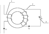
- the magnetic circuit core comprises a closed magnetic core 4, and both the first coil 1 and the second coil 2 are wound on the closed magnetic core 4, for example as shown in FIG.
- the first coil 1 may be wound on the closed magnetic circuit core 4, and the second coil 2 may be wound on the first coil 1; or, The second coil 2 is wound around the closed magnetic core 4, and the first coil 1 is wound around the second coil 2; or, the first coil 1 and the second coil 2 are wound around the closed magnetic core 4.
- the embodiment of the present invention does not limit the winding manner of the first coil 1 and the second coil 2.
- the first coil 1 and the second coil 2 may be respectively wound around the closed magnetic core 4 Different locations on the top.
- the first coil 1 is connected to the working circuit to cause the second coil 2 to generate an induced current.
- the current adjustment device 5 is used to adjust the magnitude of the current on the second coil 2, thereby changing the magnitude of the magnetic flux of the closed magnetic circuit core 4, and the inductor assembly is realized at this time.
- the adjustment of the inductance of the inductor in the middle By setting in this way, it is ensured that the magnetoresistance of the inductor is small and the magnetic induction intensity is large.
- the structure of the closed magnetic circuit core 4 may be various, for example, it may be a ring structure, or a double C-shaped structure in which the notches are butted together, or a ring structure with a slit on the side wall.
- the inductor further includes: an open magnetic core 6.
- the first coil 1 is wound around the open core 6 and the second coil 2 is wound around the first coil 1.
- the second coil 2 is wound around the open core 6 and the first coil 1 is wound around the second coil 2.
- the first coil 1 and the second coil 2 are wound around the open core 6 , and a schematic diagram of the winding manner can be seen in FIG. 4 .
- the first coil 1 is connected to the working circuit to cause the second coil 2 to generate an induced current.
- the current adjustment device 5 is used to adjust the magnitude of the current on the second coil 2, thereby changing the magnitude of the magnetic flux of the open circuit core 6, and the inductor assembly is realized.
- the adjustment of the inductance of the inductor in the middle By setting in this way, it is ensured that the magnetoresistance of the inductor is small and the magnetic induction intensity is large.
- the embodiment of the present application does not limit the structure of the open magnetic core 6 .
- the structure of the open magnetic core 6 may be a rod-like structure.
- the current regulating device 5 comprises a variable resistor 3 or a rectifying switch device.
- the variable resistor 3 and the rectifier switch device will be separately described:
- the variable resistor 3 is a resistor whose resistance can be adjusted. As shown in FIG. 5, the second coil 2 can be connected in series with the variable resistor 3 through a wire (or other optional connection), and the total resistance of the circuit in which the second coil 2 is located is equal to the resistance of the second coil 2 and the The sum of the resistances of the variable resistors 3.
- the resistance value of the variable resistor 3 is adjusted, thereby changing the total resistance of the circuit in which the second coil 2 is located, thereby changing the current of the circuit in which the second coil 2 is located. Thereafter, the magnetic flux of the second coil 2 is changed, and the inductance value of the first coil 1 is also changed accordingly, and at this time, the adjustment of the inductance of the inductor is realized.
- the rectifying switching device comprises an insulated gate bipolar transistor, or a thyristor, or a triode.
- Insulated Gate Bipolar Transistor A semiconductor component with a switching function.
- IGBT Insulated Gate Bipolar Transistor
- C represents the capacitance
- L 1 represents the inductance.
- D5 connected in parallel with the IGBT 6
- an IGBT in parallel with the first element D5 the first member constituting the first sub-circuit connected in series with the inductor L 1.
- the first sub-circuit is connected in parallel with the capacitor C to form a sub-circuit.
- both ends of the second coil 2 are connected in series with the sub-circuit through D 2 and D 3 . Accordingly, when the direction of the current I 2 in the second coil 2 is opposite to the direction shown in FIG. 6, both ends of the second coil 2 are connected in series with the sub-circuit through D 1 , D 4 . It can be seen that the second coil 2 is always in series with the sub-circuit, ie the circuit in which the second coil 2 is located is always the path.
- the switching state of the IGBT can be changed by the computer.
- the current value of the circuit in which the second coil 2 is located is decreased.
- the second coil 2 is The current value of the circuit is increased. Therefore, by adjusting the switching frequency of the IGBT by the computer, the IGBT can be regularly switched in the switching state, and the current value of the circuit where the second coil 2 is located will also change correspondingly, thereby changing the effective value of I 2 and realizing
- the current of the circuit in which the second coil 2 is located is adjustable. Therefore, the magnetic flux of the second coil 2 is changed, and the inductance value of the first coil 1 is also changed correspondingly, and at this time, the adjustment of the inductance of the inductor is realized.
- the function of the capacitor C is that when the switching state of the IGBT changes, the capacitance can change the current in the circuit where the second coil 2 is located, thereby avoiding the circuit in which the second coil 2 is located.
- the current waveform changes.
- the function of the inductor L 1 is to prevent the generation of surge current and protect the IGBT.
- the second coil 2 generates a peak current, which is a surge current.
- the induced current generated by the second coil 2 is used as a steady-state current, and the current value of the surge current is greater than the current value of the steady-state current, which may cause damage to the IGBT. Therefore, this embodiment uses L 1 to prevent the generation of a surge current, thereby protecting the IGBT.
- the thyristor is also a semiconductor element having a switching function.
- the adjustment process of the inductance of the inductor through the thyristor is the same as the process of adjusting the inductance of the inductor by the IGBT, and will not be further described herein.
- Transistor Schematic diagram of the structure of the triode is shown in Figure 7, where B, C, and E are the three electrodes of the triode.
- the current from C to E is denoted as Ic
- the current from B to E is denoted as Ib
- the value of Ic varies with the value of Ib. Therefore, the two electrodes C and E can be respectively connected to the two ends of the second coil 2, and the current of the circuit where the second coil 2 is located is Ic.
- Ic is indirectly controlled by controlling Ib, so that the second coil 2 is
- the inductance value of the first coil 1 also changes accordingly, and the inductance of the inductor is adjusted at this time.
- an embodiment of the present application provides a speaker, including: a frequency divider.
- the frequency divider includes: the above inductor assembly.
- the speaker also has the above advantages of the inductor assembly.
- the inductor assembly provided by the present application, the user can adjust the inductance according to personal preference, so that the frequency divider can better perform the speaker. Multi-way, the speaker response frequency is wider.
- the structure of the speakers is common in the art, and the placement of frequency dividers and inductor components within the speakers is also common in the art.
- the structure of the speaker can refer to the patent document: a high-fidelity speaker (application number CN00240314.5) and the like.
Landscapes
- Engineering & Computer Science (AREA)
- Power Engineering (AREA)
- Coils Or Transformers For Communication (AREA)
- Amplifiers (AREA)
Priority Applications (2)
| Application Number | Priority Date | Filing Date | Title |
|---|---|---|---|
| CN201980021874.6A CN111954913A (zh) | 2018-01-24 | 2019-01-23 | 电感器组件及音箱 |
| EP19743230.5A EP3736840B1 (de) | 2018-01-24 | 2019-01-23 | Induktoranordnung und lautsprecher |
Applications Claiming Priority (2)
| Application Number | Priority Date | Filing Date | Title |
|---|---|---|---|
| CN201810067576.8A CN108447665A (zh) | 2018-01-24 | 2018-01-24 | 一种可调电感器组件及音箱 |
| CN201810067576.8 | 2018-01-24 |
Publications (1)
| Publication Number | Publication Date |
|---|---|
| WO2019144887A1 true WO2019144887A1 (zh) | 2019-08-01 |
Family
ID=63191298
Family Applications (1)
| Application Number | Title | Priority Date | Filing Date |
|---|---|---|---|
| PCT/CN2019/072866 Ceased WO2019144887A1 (zh) | 2018-01-24 | 2019-01-23 | 电感器组件及音箱 |
Country Status (3)
| Country | Link |
|---|---|
| EP (1) | EP3736840B1 (de) |
| CN (2) | CN108447665A (de) |
| WO (1) | WO2019144887A1 (de) |
Cited By (1)
| Publication number | Priority date | Publication date | Assignee | Title |
|---|---|---|---|---|
| CN119786227A (zh) * | 2025-03-07 | 2025-04-08 | 深圳市海瑞思自动化科技有限公司 | 一种质谱用射频线圈电感量调节装置 |
Families Citing this family (4)
| Publication number | Priority date | Publication date | Assignee | Title |
|---|---|---|---|---|
| CN108447665A (zh) * | 2018-01-24 | 2018-08-24 | 北京金科华业测控技术有限公司 | 一种可调电感器组件及音箱 |
| CN110379611A (zh) * | 2019-06-26 | 2019-10-25 | 东南大学 | 一种具有永磁偏置的直流电流控制电感调谐装置 |
| CN110957659B (zh) * | 2019-11-20 | 2020-12-01 | 苏州鱼得水电气科技有限公司 | 一种移动式变电站 |
| CN118098791A (zh) * | 2022-11-28 | 2024-05-28 | 王静然 | 电感器及扬声器组件 |
Citations (6)
| Publication number | Priority date | Publication date | Assignee | Title |
|---|---|---|---|---|
| JPH05182837A (ja) * | 1992-01-07 | 1993-07-23 | Matsushita Electric Ind Co Ltd | 可変インダクタ |
| CN2455028Y (zh) * | 2000-11-29 | 2001-10-17 | 梁耀辉 | 一种高保真音箱 |
| JP2004140165A (ja) * | 2002-10-17 | 2004-05-13 | Matsushita Electric Ind Co Ltd | 可変インダクタ |
| CN202759249U (zh) * | 2012-08-23 | 2013-02-27 | 大连第二互感器集团有限公司 | 磁控并联电抗器 |
| CN203311972U (zh) * | 2013-07-11 | 2013-11-27 | 哈尔滨理工大学 | 一种带气隙直流控磁可调电抗器 |
| CN108447665A (zh) * | 2018-01-24 | 2018-08-24 | 北京金科华业测控技术有限公司 | 一种可调电感器组件及音箱 |
Family Cites Families (10)
| Publication number | Priority date | Publication date | Assignee | Title |
|---|---|---|---|---|
| US4207530A (en) * | 1977-09-12 | 1980-06-10 | Motorola, Inc. | Electrically tunable inductor and method |
| US20040012472A1 (en) * | 1997-11-28 | 2004-01-22 | Christian Sasse | Flux control for high power static electromagnetic devices |
| CN100483575C (zh) * | 2005-12-23 | 2009-04-29 | 清华大学 | 非接触式可控电抗器 |
| RU2348998C1 (ru) * | 2008-01-31 | 2009-03-10 | Александр Васильевич Григорьев | Управляемый реактор трансформаторного типа |
| CN201319287Y (zh) * | 2008-12-03 | 2009-09-30 | 上海铁路通信工厂 | 大电流空心线圈 |
| US20110260819A1 (en) * | 2010-04-26 | 2011-10-27 | Taiwan Semiconductor Manufacturing Co., Ltd. | Continuously tunable inductor with variable resistors |
| CN202309082U (zh) * | 2011-09-28 | 2012-07-04 | 武汉伏特克电气工程有限公司 | 自动无级调压式无功补偿装置 |
| CN102682955B (zh) * | 2012-05-10 | 2016-09-14 | 杭州金果科技有限公司 | 一种可调电感 |
| CN204992589U (zh) * | 2015-10-10 | 2016-01-20 | 张家港市博特圣电气科技有限公司 | 一种三相交流智能控制电路 |
| CN107509134A (zh) * | 2017-10-10 | 2017-12-22 | 李龙根 | 一种耳机用二阶无源分频器 |
-
2018
- 2018-01-24 CN CN201810067576.8A patent/CN108447665A/zh active Pending
-
2019
- 2019-01-23 EP EP19743230.5A patent/EP3736840B1/de active Active
- 2019-01-23 WO PCT/CN2019/072866 patent/WO2019144887A1/zh not_active Ceased
- 2019-01-23 CN CN201980021874.6A patent/CN111954913A/zh active Pending
Patent Citations (6)
| Publication number | Priority date | Publication date | Assignee | Title |
|---|---|---|---|---|
| JPH05182837A (ja) * | 1992-01-07 | 1993-07-23 | Matsushita Electric Ind Co Ltd | 可変インダクタ |
| CN2455028Y (zh) * | 2000-11-29 | 2001-10-17 | 梁耀辉 | 一种高保真音箱 |
| JP2004140165A (ja) * | 2002-10-17 | 2004-05-13 | Matsushita Electric Ind Co Ltd | 可変インダクタ |
| CN202759249U (zh) * | 2012-08-23 | 2013-02-27 | 大连第二互感器集团有限公司 | 磁控并联电抗器 |
| CN203311972U (zh) * | 2013-07-11 | 2013-11-27 | 哈尔滨理工大学 | 一种带气隙直流控磁可调电抗器 |
| CN108447665A (zh) * | 2018-01-24 | 2018-08-24 | 北京金科华业测控技术有限公司 | 一种可调电感器组件及音箱 |
Cited By (1)
| Publication number | Priority date | Publication date | Assignee | Title |
|---|---|---|---|---|
| CN119786227A (zh) * | 2025-03-07 | 2025-04-08 | 深圳市海瑞思自动化科技有限公司 | 一种质谱用射频线圈电感量调节装置 |
Also Published As
| Publication number | Publication date |
|---|---|
| CN111954913A (zh) | 2020-11-17 |
| EP3736840C0 (de) | 2023-08-23 |
| EP3736840B1 (de) | 2023-08-23 |
| CN108447665A (zh) | 2018-08-24 |
| EP3736840A4 (de) | 2021-03-10 |
| EP3736840A1 (de) | 2020-11-11 |
Similar Documents
| Publication | Publication Date | Title |
|---|---|---|
| WO2019144887A1 (zh) | 电感器组件及音箱 | |
| Friedli et al. | Design and performance of a 200-kHz all-SiC JFET current DC-link back-to-back converter | |
| WO2010027742A2 (en) | Voltage control and power factor correction in ac induction motors | |
| GB2580748A (en) | Controlling voltage in AC power lines | |
| US3636433A (en) | Voltage stabilizer apparatus | |
| CN201364801Y (zh) | 磁通抵消式电抗器 | |
| KR101059739B1 (ko) | 전원선의 전압 안정화 시스템 | |
| JP4411460B2 (ja) | 電圧調整変圧器 | |
| CN104485824B (zh) | 一种磁控孤立的多功能变压器 | |
| WO2017016249A1 (zh) | 一种响应速度快的多功能变压器 | |
| WO2019028804A1 (zh) | 一种磁集成电路以及功率转换装置 | |
| US12431790B2 (en) | PFC design technique for high peak load | |
| WO2021248340A1 (zh) | 一种电感器以及相关装置 | |
| WO2016141614A1 (zh) | 一种结构简单的饱和电抗器 | |
| RU2065654C1 (ru) | Управляемый реактор | |
| CN104465056A (zh) | 一种可控电阻的直流饱和电抗器 | |
| WO2023279925A1 (zh) | 一种电感器 | |
| WO2016180219A1 (zh) | 一种缩短暂态响应时间的饱和电抗器 | |
| CN107993815A (zh) | 一种高压直流换流阀用磁控饱和电抗器及直流换流阀 | |
| KR20030062596A (ko) | 사이리스터를 이용한 사고전류 크기조절이 가능한고온초전도 전류제한장치 | |
| JP2562853B2 (ja) | 整流装置 | |
| RU2554712C1 (ru) | Стабилизатор - регулятор напряжения переменного тока | |
| TWI508113B (zh) | 可調式限流控制器 | |
| CN104485213A (zh) | 一种减小晶闸管耐压的直流饱和电抗器 | |
| RU2829328C1 (ru) | Стабилизатор-регулятор напряжения переменного тока |
Legal Events
| Date | Code | Title | Description |
|---|---|---|---|
| 121 | Ep: the epo has been informed by wipo that ep was designated in this application |
Ref document number: 19743230 Country of ref document: EP Kind code of ref document: A1 |
|
| NENP | Non-entry into the national phase |
Ref country code: DE |
|
| ENP | Entry into the national phase |
Ref document number: 2019743230 Country of ref document: EP Effective date: 20200804 |