WO2019146021A1 - Procédé de traitement au laser et système de traitement au laser - Google Patents
Procédé de traitement au laser et système de traitement au laser Download PDFInfo
- Publication number
- WO2019146021A1 WO2019146021A1 PCT/JP2018/002152 JP2018002152W WO2019146021A1 WO 2019146021 A1 WO2019146021 A1 WO 2019146021A1 JP 2018002152 W JP2018002152 W JP 2018002152W WO 2019146021 A1 WO2019146021 A1 WO 2019146021A1
- Authority
- WO
- WIPO (PCT)
- Prior art keywords
- laser
- laser processing
- fluence
- transfer
- light
- Prior art date
- Legal status (The legal status is an assumption and is not a legal conclusion. Google has not performed a legal analysis and makes no representation as to the accuracy of the status listed.)
- Ceased
Links
Images














Classifications
-
- B—PERFORMING OPERATIONS; TRANSPORTING
- B23—MACHINE TOOLS; METAL-WORKING NOT OTHERWISE PROVIDED FOR
- B23K—SOLDERING OR UNSOLDERING; WELDING; CLADDING OR PLATING BY SOLDERING OR WELDING; CUTTING BY APPLYING HEAT LOCALLY, e.g. FLAME CUTTING; WORKING BY LASER BEAM
- B23K26/00—Working by laser beam, e.g. welding, cutting or boring
- B23K26/02—Positioning or observing the workpiece, e.g. with respect to the point of impact; Aligning, aiming or focusing the laser beam
- B23K26/06—Shaping the laser beam, e.g. by masks or multi-focusing
- B23K26/064—Shaping the laser beam, e.g. by masks or multi-focusing by means of optical elements, e.g. lenses, mirrors or prisms
- B23K26/066—Shaping the laser beam, e.g. by masks or multi-focusing by means of optical elements, e.g. lenses, mirrors or prisms by using masks
-
- B—PERFORMING OPERATIONS; TRANSPORTING
- B23—MACHINE TOOLS; METAL-WORKING NOT OTHERWISE PROVIDED FOR
- B23K—SOLDERING OR UNSOLDERING; WELDING; CLADDING OR PLATING BY SOLDERING OR WELDING; CUTTING BY APPLYING HEAT LOCALLY, e.g. FLAME CUTTING; WORKING BY LASER BEAM
- B23K26/00—Working by laser beam, e.g. welding, cutting or boring
- B23K26/0006—Working by laser beam, e.g. welding, cutting or boring taking account of the properties of the material involved
-
- B—PERFORMING OPERATIONS; TRANSPORTING
- B23—MACHINE TOOLS; METAL-WORKING NOT OTHERWISE PROVIDED FOR
- B23K—SOLDERING OR UNSOLDERING; WELDING; CLADDING OR PLATING BY SOLDERING OR WELDING; CUTTING BY APPLYING HEAT LOCALLY, e.g. FLAME CUTTING; WORKING BY LASER BEAM
- B23K26/00—Working by laser beam, e.g. welding, cutting or boring
- B23K26/02—Positioning or observing the workpiece, e.g. with respect to the point of impact; Aligning, aiming or focusing the laser beam
- B23K26/03—Observing, e.g. monitoring, the workpiece
-
- B—PERFORMING OPERATIONS; TRANSPORTING
- B23—MACHINE TOOLS; METAL-WORKING NOT OTHERWISE PROVIDED FOR
- B23K—SOLDERING OR UNSOLDERING; WELDING; CLADDING OR PLATING BY SOLDERING OR WELDING; CUTTING BY APPLYING HEAT LOCALLY, e.g. FLAME CUTTING; WORKING BY LASER BEAM
- B23K26/00—Working by laser beam, e.g. welding, cutting or boring
- B23K26/02—Positioning or observing the workpiece, e.g. with respect to the point of impact; Aligning, aiming or focusing the laser beam
- B23K26/04—Automatically aligning, aiming or focusing the laser beam, e.g. using the back-scattered light
- B23K26/046—Automatically focusing the laser beam
- B23K26/048—Automatically focusing the laser beam by controlling the distance between laser head and workpiece
-
- B—PERFORMING OPERATIONS; TRANSPORTING
- B23—MACHINE TOOLS; METAL-WORKING NOT OTHERWISE PROVIDED FOR
- B23K—SOLDERING OR UNSOLDERING; WELDING; CLADDING OR PLATING BY SOLDERING OR WELDING; CUTTING BY APPLYING HEAT LOCALLY, e.g. FLAME CUTTING; WORKING BY LASER BEAM
- B23K26/00—Working by laser beam, e.g. welding, cutting or boring
- B23K26/02—Positioning or observing the workpiece, e.g. with respect to the point of impact; Aligning, aiming or focusing the laser beam
- B23K26/06—Shaping the laser beam, e.g. by masks or multi-focusing
- B23K26/062—Shaping the laser beam, e.g. by masks or multi-focusing by direct control of the laser beam
- B23K26/0622—Shaping the laser beam, e.g. by masks or multi-focusing by direct control of the laser beam by shaping pulses
-
- B—PERFORMING OPERATIONS; TRANSPORTING
- B23—MACHINE TOOLS; METAL-WORKING NOT OTHERWISE PROVIDED FOR
- B23K—SOLDERING OR UNSOLDERING; WELDING; CLADDING OR PLATING BY SOLDERING OR WELDING; CUTTING BY APPLYING HEAT LOCALLY, e.g. FLAME CUTTING; WORKING BY LASER BEAM
- B23K26/00—Working by laser beam, e.g. welding, cutting or boring
- B23K26/02—Positioning or observing the workpiece, e.g. with respect to the point of impact; Aligning, aiming or focusing the laser beam
- B23K26/06—Shaping the laser beam, e.g. by masks or multi-focusing
- B23K26/062—Shaping the laser beam, e.g. by masks or multi-focusing by direct control of the laser beam
- B23K26/0622—Shaping the laser beam, e.g. by masks or multi-focusing by direct control of the laser beam by shaping pulses
- B23K26/0624—Shaping the laser beam, e.g. by masks or multi-focusing by direct control of the laser beam by shaping pulses using ultrashort pulses, i.e. pulses of 1 ns or less
-
- B—PERFORMING OPERATIONS; TRANSPORTING
- B23—MACHINE TOOLS; METAL-WORKING NOT OTHERWISE PROVIDED FOR
- B23K—SOLDERING OR UNSOLDERING; WELDING; CLADDING OR PLATING BY SOLDERING OR WELDING; CUTTING BY APPLYING HEAT LOCALLY, e.g. FLAME CUTTING; WORKING BY LASER BEAM
- B23K26/00—Working by laser beam, e.g. welding, cutting or boring
- B23K26/02—Positioning or observing the workpiece, e.g. with respect to the point of impact; Aligning, aiming or focusing the laser beam
- B23K26/06—Shaping the laser beam, e.g. by masks or multi-focusing
- B23K26/0665—Shaping the laser beam, e.g. by masks or multi-focusing by beam condensation on the workpiece, e.g. for focusing
-
- B—PERFORMING OPERATIONS; TRANSPORTING
- B23—MACHINE TOOLS; METAL-WORKING NOT OTHERWISE PROVIDED FOR
- B23K—SOLDERING OR UNSOLDERING; WELDING; CLADDING OR PLATING BY SOLDERING OR WELDING; CUTTING BY APPLYING HEAT LOCALLY, e.g. FLAME CUTTING; WORKING BY LASER BEAM
- B23K26/00—Working by laser beam, e.g. welding, cutting or boring
- B23K26/36—Removing material
- B23K26/38—Removing material by boring or cutting
- B23K26/382—Removing material by boring or cutting by boring
-
- B—PERFORMING OPERATIONS; TRANSPORTING
- B23—MACHINE TOOLS; METAL-WORKING NOT OTHERWISE PROVIDED FOR
- B23K—SOLDERING OR UNSOLDERING; WELDING; CLADDING OR PLATING BY SOLDERING OR WELDING; CUTTING BY APPLYING HEAT LOCALLY, e.g. FLAME CUTTING; WORKING BY LASER BEAM
- B23K2103/00—Materials to be soldered, welded or cut
- B23K2103/50—Inorganic materials other than metals or composite materials
- B23K2103/54—Glass
Definitions
- the present disclosure relates to a laser processing method and a laser processing system.
- the semiconductor exposure apparatus is hereinafter simply referred to as "exposure apparatus". For this reason, shortening of the wavelength of the light output from the light source for exposure is advanced.
- a gas laser device is used in place of a conventional mercury lamp.
- KrF excimer laser devices that output ultraviolet light with a center wavelength of about 248.4 nm and ArF excimer laser devices that output ultraviolet light with a center wavelength of about 193.4 nm are used as gas laser devices for exposure.
- Spectral line widths are also referred to as spectral widths. Therefore, a line narrowing module (Line Narrow Module) having a band narrowing element is provided in the laser resonator of the gas laser device, and narrowing of the spectrum width is realized by this band narrowing module.
- the narrowing element may be an etalon or a grating.
- the laser device whose spectrum width is narrowed as described above is called a narrow banded laser device.
- the excimer laser light has a pulse width of 1 ns to 100 ns, and center wavelengths are as short as 248.4 nm and 193.4 nm, respectively.
- Excimer laser light may be used for direct processing of a polymeric material, a glass material, etc. other than exposure use using such characteristics.
- the polymeric material can break the bond of the polymeric material by excimer laser light having photon energy higher than the binding energy. Therefore, it is known that non-heat processing is possible and the processing shape is beautiful.
- glass, ceramics, etc. have a high absorptivity for excimer laser light, it is possible to process materials that are difficult to process with visible and infrared laser light.
- a laser device that outputs pulsed laser light of ultraviolet light, a transfer mask on which a transfer pattern that transmits the pulse laser light is formed, and the pulse laser light transmits the transfer pattern.
- Laser processing method for performing laser processing on a transparent material transparent to ultraviolet light using a laser processing system including a transfer optical system for transferring a transfer image having a shape corresponding to a transfer pattern formed by It has the following steps: A. It is a positioning step which performs relative positioning between the transfer position of the transfer image transferred by the transfer optical system and the transparent material in the optical axis direction of the pulse laser light, wherein the transfer position is the transparent material in the optical axis direction.
- a control step which allows irradiation of pulsed laser light when it is determined that the maximum fluence is within a predetermined range
- the target fluence is the cross section of the beam in the direction orthogonal to the optical axis of the pulsed laser light, and is the average fluence within the cross section of the beam at the transfer position
- the maximum fluence is the beam at the surface of the transparent material Is divided into a plurality of subregions, which is the maximum value of the fluences of the divided subregions.
- a laser processing method uses a laser processing system including a laser device that outputs pulsed laser light of ultraviolet light and a condensing optical system that condenses the pulsed laser light, for ultraviolet light.
- the laser processing method for applying laser processing to a transparent transparent material comprises the following steps: A. A positioning step for relative positioning between the beam waist position of the pulse laser beam and the transparent material in the optical axis direction of the pulse laser beam, wherein the beam waist position is predetermined from the surface of the transparent material in the optical axis direction Positioning step for positioning so as to be a position where it has entered the inside of the transparent material by a depth ⁇ Zsfw; B.
- the target fluence is the cross section of the beam in the direction orthogonal to the optical axis of the pulsed laser light, and is the average fluence in the cross section of the beam at the beam waist position, and the maximum fluence is at the surface of the transparent material
- the cross section of the beam is divided into a plurality of sub-regions, which is the maximum value of the fluence of each divided sub-region.
- a laser processing system for applying a pulsed laser beam of ultraviolet light to a transparent material transparent to ultraviolet light to perform laser processing, comprising: A. A laser device for outputting pulsed laser light; B. A transfer mask having a transfer pattern formed thereon for transmitting pulse laser light output from the laser device; C. A transfer optical system for transferring a transfer image of a shape corresponding to the transfer pattern, formed by transmitting a transfer pattern of pulsed laser light onto a transparent material; D.
- a positioning mechanism that performs relative positioning between a transfer position of a transfer image transferred by the transfer optical system and the transparent material in the optical axis direction of the pulse laser beam, wherein the transfer position is of the transparent material in the optical axis direction
- a positioning mechanism for positioning so as to be a position where it has entered the inside of the transparent material by a predetermined depth ⁇ Zsf from the surface;
- An irradiation condition acquisition unit for acquiring an irradiation condition including a target fluence of pulse laser light at a transfer position and a depth ⁇ Zsf;
- a determination unit that determines whether or not the maximum fluence of pulse laser light on the surface of the transparent material is within a predetermined range based on the irradiation condition;
- a control unit that allows irradiation of pulsed laser light when it is determined that the maximum fluence is within a predetermined range,
- the target fluence is the cross section of the beam in the direction orthogonal to the optical axis of the pulsed laser light, and is the average fluence within the cross section of the beam at the transfer position
- the maximum fluence is the beam at the surface of the transparent material Is divided into a plurality of subregions, which is the maximum value of the fluences of the divided subregions.
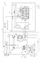
- FIG. 1 schematically shows the configuration of a laser processing system of a comparative example.
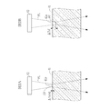
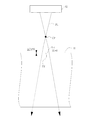
- FIG. 2 is an explanatory view of the transfer position FP.
- FIG. 2A is an example in which the transfer position FP is set on the surface of the workpiece
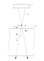
- FIG. 2B is an example in which the transfer position FP is set at a position where the transfer position FP is advanced from the surface of the workpiece.
- FIG. 3 is a flowchart showing the laser processing procedure of the comparative example.
- FIG. 4 is a flowchart showing the processing procedure of laser processing of the comparative example.
- FIG. 1 schematically shows the configuration of a laser processing system of a comparative example.
- FIG. 2 is an explanatory view of the transfer position FP.
- FIG. 2A is an example in which the transfer position FP is set on the surface of the workpiece
- FIG. 2B is an example in which the transfer position FP is set at a position where the transfer position FP is advanced from the surface of the workpiece.
- FIG. 5 is an explanatory view showing a state transition of a workpiece when laser processing is performed in the first embodiment.
- FIG. 5A shows a state in which the pulse laser beam is irradiated according to the position where the transfer position of the pulse laser beam is advanced to the inside by the depth ⁇ Zsf from the surface of the workpiece.
- FIG. 5B shows the processing state of the workpiece immediately after pulsed laser irradiation.
- FIG. 5C shows a state where the pulse laser light is self-focusing.
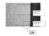
- FIG. 5D shows the processing state of the workpiece by irradiation of pulse laser light.
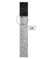
- FIG. 6 is an explanatory view of a crack CR generated in the hole H near the surface.
- FIG. 7 is a photograph of the crack CR.
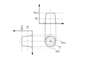
- FIG. 8 is an explanatory view of a top hat beam profile.
- FIG. 9 is an explanatory view of a beam profile of Gaussian distribution.
- FIG. 10 is an explanatory view of the fluence of a small area which is the basis for determining the maximum fluence.
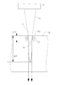
- FIG. 11 is an explanatory view showing an aspect of focusing and divergence of a luminous flux of pulse laser light using a transfer optical system.
- FIG. 12 is an explanatory view showing an aspect of a luminous flux of pulse laser light when the transfer position FP is inside the workpiece 41.
- FIG. 13 is measurement data showing the shape of the cross section SP of the beam and the light intensity distribution at each distance ZL from the transfer position FP.
- FIG. 13 is measurement data showing the shape of the cross section SP of the beam and the light intensity distribution at each distance ZL from the transfer position FP.
- FIG. 13A is measurement data of the position where the distance ZL is the largest.
- FIG. 13E is measurement data at the transfer position FP where the distance ZL is “0”.
- 13C and 13D are measurement data at each distance ZL between FIGS. 13A and 13E.
- FIG. 14 is a graph showing correlation data of the distance ZL and the light intensity ratio R.
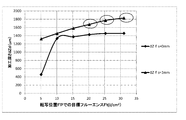
- FIG. 15 is a first graph showing the relationship between the target fluence Ft at the transfer position FP and the processing depth ⁇ Zd.
- FIG. 16 is a second graph of another condition different from FIG.
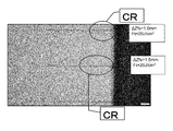
- FIG. 17 is a photograph showing the occurrence of cracks CR when processed under the conditions included in the graphs of FIG. 15 and
- FIG. 18 is a third graph of another condition different from FIG. FIG.
- FIG. 19 is a fourth graph of conditions different from FIG.
- FIG. 20 is a photograph showing the occurrence of cracks CR when processed under the conditions included in the graphs of FIGS. 19 and 18.
- FIG. 21 is a table summarizing the experimental results shown in FIG. 15 to FIG.
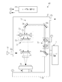
- FIG. 22 schematically shows the configuration of the laser processing system of the first embodiment.
- FIG. 23 is a flowchart showing the laser processing procedure of the first embodiment.
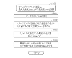
- FIG. 24 is a flowchart showing the evaluation procedure of the maximum fluence of the first embodiment.
- FIG. 25 is a graph showing the relationship between the irradiation pulse number N and the processing depth ⁇ Zd.
- FIG. 26 schematically illustrates the configuration of the laser processing system according to the second embodiment.
- FIG. 27 is an explanatory view showing an aspect of pulse laser light in the case of using a focusing optical system.
- FIG. 28 is an explanatory view of a beam waist position and a beam profile on the surface of a workpiece.
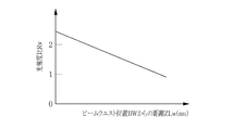
- FIG. 29 is a graph showing correlation data between the distance ZLw and the light intensity ratio R according to the second embodiment.
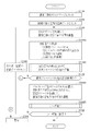
- FIG. 30 is a flowchart showing the laser processing procedure of the second embodiment.
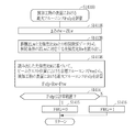
- FIG. 31 is a flow chart showing the evaluation procedure of the maximum fluence of the second embodiment.
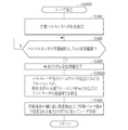
- FIG. 32 is a flowchart showing the processing procedure of laser processing.
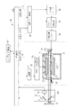
- FIG. 33 shows the outline of the configuration of the laser processing system of the third embodiment.
- FIG. 34 is a flowchart showing a procedure of acquiring correlation data.
- FIG. 35 is a flowchart showing the calculation procedure of the maximum light intensity and the average light intensity.
- FIG. 36 is a flowchart showing the calculation procedure of the maximum light intensity.
- FIG. 37 shows a first modification of the laser processing apparatus.
- FIG. 38 shows a second modification of the laser processing apparatus.
- FIG. 39 shows a first modification of the laser device.
- FIG. 40 shows a second modification of the laser device.
- ⁇ Content> 1. Overview 2. Laser processing system and laser processing method according to comparative example 2.1 Configuration 2.1.1 Overall configuration 2.1.2 Depth ⁇ Zsf of transfer position 2.2 Operation 2.2.1 Estimation mechanism of high aspect ratio drilling 2.3 Problem 3. Analysis of causes of cracks 4.
- the laser processing system and the laser processing method according to the first embodiment 4.1 Configuration 4.2 Operation 4.3 Operation 4.4 Preferred Processing Conditions 4.4.1 Pulse Width of Pulsed Laser Light 4.4.2 Diameter of Beam Di 4.4.3 Preferred conditions when the workpiece 41 is a synthetic quartz glass 4.4.3.1 Wavelength of pulsed laser light 4.4.3.2 Range of depth ⁇ Zsf 4.4.3.
- the present disclosure relates to a laser processing system and a laser processing method for performing laser processing by irradiating a workpiece with laser light.
- FIG. 1 schematically shows the configuration of a laser processing system according to a comparative example.
- the laser processing system 2 includes a laser device 3 and a laser processing device 4.
- the laser device 3 and the laser processing device 4 are connected by an optical path tube 5.
- the laser device 3 includes a master oscillator 10, a monitor module 11, a shutter 12, and a laser control unit 13.
- the laser device 3 is an ArF excimer laser device that uses an ArF laser gas containing argon (Ar) and fluorine (F) as a laser medium.
- the laser device 3 outputs pulsed laser light of ultraviolet light, which is ArF laser light having a center wavelength of about 193.4 nm.
- the master oscillator 10 includes a laser chamber 21, a pair of electrodes 22 a and 22 b, a charger 23, and a pulse power module (PPM) 24.
- FIG. 1 shows the internal configuration of the laser chamber 21 as viewed from a direction substantially perpendicular to the traveling direction of the laser beam.
- the laser chamber 21 is a chamber in which an ArF laser gas is sealed.
- the pair of electrodes 22a and 22b are disposed in the laser chamber 21 as electrodes for exciting the laser medium by a discharge.
- An opening is formed in the laser chamber 21, and the opening is closed by the electrical insulator 28.
- the electrode 22a is supported by the electrical insulator 28, and the electrode 22b is supported by the return plate 21d.
- the return plate 21 d is connected to the inner surface of the laser chamber 21 by a wire (not shown).
- a conductive portion is embedded in the electrical insulating portion 28. The conductive unit applies a high voltage supplied from the pulse power module 24 to the electrode 22a.
- the charger 23 is a DC power supply device that charges a charging capacitor (not shown) in the pulse power module 24 with a predetermined voltage.
- the pulse power module 24 includes a switch 24 a controlled by the laser control unit 13. When the switch 24a is turned from OFF to ON, the pulse power module 24 generates a pulsed high voltage from the electrical energy held by the charger 23, and applies this high voltage between the pair of electrodes 22a and 22b.
- Windows 21 a and 21 b are provided at both ends of the laser chamber 21.
- the light generated in the laser chamber 21 is emitted to the outside of the laser chamber 21 through the windows 21 a and 21 b.
- Master oscillator 10 further includes a rear mirror 26 and an output coupling mirror 27.
- the rear mirror 26 is coated with a high reflection film
- the output coupling mirror 27 is coated with a partial reflection film.
- the rear mirror 26 reflects the light emitted from the window 21 a of the laser chamber 21 with high reflectance back to the laser chamber 21.
- the output coupling mirror 27 transmits and outputs a part of the light output from the window 21 b of the laser chamber 21 and reflects the other part back into the laser chamber 21.
- an optical resonator is configured by the rear mirror 26 and the output coupling mirror 27.
- the laser chamber 21 is disposed on the optical path of the optical resonator.
- the light emitted from the laser chamber 21 reciprocates between the rear mirror 26 and the output coupling mirror 27, and is amplified each time it passes through the laser gain space between the electrode 22a and the electrode 22b. A part of the amplified light is output as pulsed laser light through the output coupling mirror 27.
- the monitor module 11 is disposed on the optical path of the pulse laser beam emitted from the master oscillator 10.
- the monitor module 11 includes, for example, a beam splitter 11a and an optical sensor 11b.
- the beam splitter 11a transmits the pulse laser beam emitted from the master oscillator 10 toward the shutter 12 with high transmittance, and reflects a part of the pulse laser beam toward the light receiving surface of the optical sensor 11b.
- the optical sensor 11 b detects pulse energy of the pulse laser light incident on the light receiving surface, and outputs data of the detected pulse energy to the laser control unit 13.
- the laser control unit 13 transmits and receives various signals to and from the laser processing control unit 32.
- the laser control unit 13 receives, from the laser processing control unit 32, data of the light emission trigger Tr, the target pulse energy Et, and the like. Further, the laser control unit 13 transmits a setting signal of the charging voltage to the charger 23 and transmits an instruction signal of ON or OFF of the switch 24 a to the pulse power module 24.
- the laser control unit 13 receives pulse energy data from the monitor module 11 and controls the charging voltage of the charger 23 with reference to the received pulse energy data. By controlling the charging voltage of the charger 23, the pulse energy of the pulsed laser light is controlled.
- the shutter 12 is disposed in the optical path of the pulse laser beam transmitted through the beam splitter 11 a of the monitor module 11.
- the laser control unit 13 controls the shutter 12 to be closed until the difference between the pulse energy received from the monitor module 11 and the target pulse energy Et falls within the allowable range after the start of laser oscillation.
- the laser control unit 13 controls the shutter 12 to open when the difference between the pulse energy received from the monitor module 11 and the target pulse energy Et is within the allowable range.
- the laser control unit 13 transmits, to the laser processing control unit 32 of the laser processing apparatus 4, a signal indicating that reception of the light emission trigger Tr of the pulse laser light has become possible in synchronization with the open / close signal of the shutter 12.
- the laser processing apparatus 4 includes a laser processing control unit 32, a table 33, an XYZ stage 34, an optical system 36, a housing 37, and a frame 38.
- An optical system 36 is disposed in the housing 37.
- the housing 37 and the XYZ stage 34 are fixed to the frame 38.
- the table 33 supports the workpiece 41.
- the workpiece 41 is a processing target to which laser processing is performed by irradiation with pulse laser light.
- the workpiece 41 is a transparent material transparent to ultraviolet pulse laser light, and is, for example, synthetic quartz glass.
- the laser processing is, for example, a hole processing for making a hole in the workpiece 41.
- the XYZ stage 34 supports the table 33.
- the XYZ stage 34 is movable in the X-axis direction, the Y-axis direction, and the Z-axis direction, and by adjusting the position of the table 33, the position of the workpiece 41 can be adjusted.
- the XYZ stage 34 adjusts the position of the workpiece 41 so that the pulsed laser light emitted from the optical system 36 is irradiated to a desired processing position under the control of the laser processing control unit 32.
- the laser processing system 2 performs, for example, drilling at one position or a plurality of positions of the workpiece 41.
- Position data corresponding to a plurality of processing positions are sequentially set in the laser processing control unit 32.
- the position data of each processing position is, for example, coordinate data that defines each position of each processing position in the X-axis direction, the Y-axis direction, and the Z-axis direction based on the origin position of the XYZ stage 34.
- the laser processing control unit 32 controls the movement amount of the XYZ stage 34 based on such coordinate data, and positions the workpiece 41 on the XYZ stage 34.
- the optical system 36 includes, for example, high reflection mirrors 36a to 36c, a transfer mask 47, and a transfer lens 48, and transfers an image corresponding to the processing shape on the surface of the workpiece 41.
- the high reflection mirrors 36a to 36c, the transfer mask 47 and the transfer lens 48 are each fixed to a holder (not shown), and arranged at a predetermined position in the housing 37.
- the high reflection mirrors 36a to 36c reflect pulse laser light in the ultraviolet region with high reflectance.
- the high reflection mirror 36a reflects the pulse laser light input from the laser device 3 toward the high reflection mirror 36b, and the high reflection mirror 36b reflects the pulse laser light toward the high reflection mirror 36c.
- the high reflection mirror 36 c reflects the pulse laser light toward the transfer lens 48.
- the high reflection mirrors 36a to 36c are, for example, coated with a reflective film that reflects pulse laser light highly on the surface of a transparent substrate made of synthetic quartz or calcium fluoride.
- the transfer mask 47 is disposed on the light path between the high reflection mirrors 36 b and 36 c.
- the transfer mask 47 transmits a part of the pulse laser beam reflected by the high reflection mirror 36 b to form an image of the pulse laser beam corresponding to the processing shape of the workpiece 41.
- the transfer mask 47 is, for example, a light blocking plate having a light blocking property to block pulse laser light, and a transfer pattern formed of transmission holes for transmitting light is formed.
- an image of pulse laser light formed in accordance with the shape of the transfer pattern of the transfer mask 47 is referred to as a transfer image.
- the transfer pattern of the transfer mask 47 is a circular pinhole.
- the laser processing apparatus 4 of this example performs hole processing on the workpiece 41 to form a hole having a circular cross section.
- the transfer mask 47 is provided with a variable mechanism capable of changing the size of the pinhole, and the size of the pinhole can be adjusted in accordance with the processing size of the workpiece 41.
- the laser processing control unit 32 controls the variable mechanism of the transfer mask 47 to adjust the size of the pinhole.
- the transfer lens 48 condenses the incident pulse laser beam, and emits the collected pulse laser beam toward the workpiece 41 through the window 42.
- the transfer lens 48 constitutes a transfer optical system for forming a pinhole-shaped transfer image of pulse laser light generated by transmitting the transfer mask 47 at a position according to the focal distance of the transfer lens 48.
- an imaging position at which a transfer image is formed by the action of the transfer lens 48 is referred to as a transfer position.
- the position of the transfer position in the Z-axis direction is set to a predetermined position based on the surface on the incident side where the pulse laser beam is incident, based on the irradiation conditions acquired in advance. Positioning of the transfer position in the Z-axis direction corresponds to positioning of the pulse laser beam in the optical axis direction. The positioning of the transfer position will be described later. Further, hereinafter, when the surface of the workpiece 41 is simply referred to, the surface on the incident side of the workpiece 41 is meant.
- the Z-axis direction is parallel to the optical axis direction of the pulse laser beam that is emitted from the transfer lens 48 and is incident on the workpiece 41.
- the transfer lens 48 is configured by a combination of a plurality of lenses.
- the transfer lens 48 is a reduction optical system that forms a pinhole-shaped transfer image of a size smaller than the actual size of the pinhole provided in the transfer mask 47 at the transfer position.
- the transfer lens 48 is shown as an example of a combination lens, but when one small circular transfer image is formed in the vicinity of the optical axis of the transfer lens 48, the transfer lens 48 is configured by a single lens. You may
- the window 42 is disposed on the optical path between the transfer lens 48 and the workpiece 41, and is fixed in an opening formed in the housing 37 in a sealed state by an O-ring (not shown).
- the attenuator 52 is disposed on the optical path between the high reflection mirror 36 a and the high reflection mirror 36 b in the housing 37.
- the attenuator 52 includes, for example, two partially reflecting mirrors 52a and 52b, and rotation stages 52c and 52d of these partially reflecting mirrors.
- the two partial reflection mirrors 52a and 52b are optical elements whose transmittance changes according to the incident angle of the pulse laser light.
- the tilt angles of the partial reflection mirror 52a and the partial reflection mirror 52b are adjusted by the rotation stage 52c and the rotation stage 52d such that the incident angles of the pulse laser light coincide with each other and the desired transmittance is obtained.
- the pulse laser light is attenuated to a desired pulse energy and passes through the attenuator 52.
- the transmittance T of the attenuator 52 is controlled based on the control signal of the laser processing controller 32.
- the laser processing control unit 32 controls the transmittance T of the attenuator 52 to control the fluence of the pulsed laser light, in addition to controlling the fluence of the pulsed laser light output from the laser device 3 through the target pulse energy Et. .
- it is possible to change the fluence by changing the target pulse energy Et it is difficult for the master oscillator 10 of the laser device 3 to change the pulse energy largely.
- the attenuator 52 even if the output of the master oscillator 10 is constant, the fluence can be changed.
- nitrogen (N 2 ) gas which is an inert gas
- the housing 37 is provided with a suction port 37a for sucking nitrogen gas into the housing 37, and a discharge port 37b for discharging nitrogen gas from the housing 37 to the outside.
- An intake pipe and an exhaust pipe can be connected to the intake port 37a and the exhaust port 37b.
- the suction port 37a and the discharge port 37b are sealed by an O-ring (not shown) so as to suppress the mixing of the outside air into the housing 37 when the intake pipe and the discharge pipe are connected.
- a nitrogen gas supply source 43 is connected to the suction port 37a. Further, the light path in the laser device 3 is sealed and purged with nitrogen gas which is an inert gas.
- Nitrogen gas also flows in the optical path tube 5, and the optical path tube 5 is also sealed by an O-ring at the connection portion of the laser processing device 4 and the connection portion with the laser device 3.
- the laser processing control unit 32 performs relative positioning between the transfer position FP of the pulse laser beam PL and the workpiece 41 in the Z-axis direction with reference to the surface 41 a of the workpiece 41. . Specifically, the laser processing control unit 32 positions the transfer position FP such that the transfer position FP is advanced from the surface 41 a of the workpiece 41 by a predetermined depth ⁇ Zsf into the interior of the workpiece 41 in the optical axis direction. I do. The depth ⁇ Zsf is input as the irradiation condition. The laser processing control unit 32 controls the XYZ stage 34 according to the value of the depth ⁇ Zsf to position the transfer position FP and the workpiece 41 in the Z-axis direction.
- the transfer position FP is set to the position of the surface 41a. In this case, the transfer position FP coincides with the surface 41 a of the workpiece 41 in the Z-axis direction.
- the transfer position FP is set at a position where the transfer position FP has entered the inside by the depth ⁇ Zsf from the surface 41a.
- the laser processing control unit 32 corresponds to a positioning control unit that performs relative positioning between the transfer position FP and the workpiece 41 in the optical axis direction of the pulse laser beam by controlling the XYZ stage 34 that is a positioning mechanism. Do.
- the operation of the laser processing system 2 will be described with reference to FIGS. 3 and 4.
- the workpiece 41 is set on the table 33 of the XYZ stage 34 (S1100).
- the laser processing control unit 32 sets position data of the initial processing position on the XYZ stage 34 (S1200).
- the laser processing control unit 32 controls the XYZ stage 34 to adjust the position of the XY plane of the workpiece 41 (S1300).
- the laser processing control unit 32 adjusts the position of the workpiece 41 in the XY plane by controlling the movement amount of the XYZ stage 34 based on the coordinate data in the XY plane included in the position data. Thereby, the position in the XY plane of the to-be-processed object 41 is positioned.
- the laser processing control unit 32 acquires the irradiation conditions of the pulse laser beam PL (S1400).
- the data of the irradiation conditions are manually input from the operation panel or the like by the operation of the operator, for example, and stored in the memory in the laser processing control unit 32 or an external data storage.
- the laser processing control unit 32 acquires the irradiation condition by reading out the data of the irradiation condition from the memory or the data storage.
- the irradiation conditions include the target fluence Ft at the transfer position FP, the depth ⁇ Zsf of the transfer position FP, the number N of irradiation pulses of the pulsed laser light to be irradiated, and the repetition frequency f of the pulsed laser light.
- the depth ⁇ Zsf is included in the position data set in S1200.
- the laser processing control unit 32 controls the XYZ stage 34 so that the transfer position FP of the transfer image of the pulse laser light PL becomes the depth ⁇ Zsf of the irradiation condition, and the Z axis direction of the workpiece 41 Adjust the position of (S1500).
- the transfer position FP is determined according to the distance between the transfer mask 47 and the transfer lens 48, the focal length of the transfer lens 48, and the like. Therefore, in S1500, the laser processing control unit 32 controls the amount of movement of the XYZ stage 34 to make the relative position between the transfer position FP of the transfer image of the pulse laser beam PL and the surface 41a of the workpiece 41 in the Z-axis direction. Positioning. As described above, since the Z-axis direction is parallel to the optical axis direction of the pulse laser beam incident on the workpiece 41, the positioning in the Z-axis direction corresponds to the positioning in the optical axis direction of the pulse laser beam.
- laser processing is performed (S1600).
- the laser processing control unit 32 sets position data of the next processing position on the XYZ stage 34 when there is the next processing position (N in S1700) ( S1800). Then, the laser processing control unit 32 moves the workpiece 41 to the next processing position and acquires the irradiation condition (S1300 to S1500). Laser processing is performed on the workpiece 41 at the next processing position (S1600). When there is no next processing position, laser processing is completed (Y in S1700). These procedures are repeated until laser processing for all processing positions is completed.
- both the position in the XY plane and the position in the Z-axis direction are adjusted for each processing position.
- irradiation conditions are acquired for each processing position.
- the positions in the Z-axis direction are the same and the irradiation conditions are the same among the plurality of processing positions, the following may be performed.
- steps S1400 and S1500 may be omitted about the processing position after that.
- step S1200 of setting the position data of the initial processing position first, step S1400 of acquiring the irradiation condition and step S1500 of adjusting the position in the Z-axis direction are performed.
- step S1300 is performed to adjust the position of the XY plane with respect to the initial processing position, and step SS1600 is performed.
- step S1800 is performed for the next processing position, only step S1300 is performed, steps S1400 and S1500 are omitted, and step S1600 is performed.
- the laser processing of S1600 in FIG. 3 is performed according to the flowchart shown in FIG.
- the laser processing control unit 32 transmits the target pulse energy Et to the laser control unit 13 of the laser device 3.
- the target pulse energy Et is set in the laser control unit 13 (S1601).
- the laser control unit 13 When receiving the target pulse energy Et from the laser processing control unit 32, the laser control unit 13 closes the shutter 12 and operates the charger 23. Then, the laser control unit 13 turns on the switch 24 a of the pulse power module 24 by an internal trigger (not shown). Thereby, the master oscillator 10 oscillates laser.
- the monitor module 11 samples pulse laser light output from the master oscillator 10 and measures pulse energy E which is an actual measurement value of pulse energy.
- the laser control unit 13 controls the charging voltage of the charger 23 such that the difference ⁇ E between the pulse energy E and the target pulse energy Et approaches zero. Specifically, the laser control unit 13 controls the charging voltage such that the difference ⁇ E falls within the allowable range.
- the laser control unit 13 monitors whether or not the difference ⁇ E is in the allowable range (S1602). When the difference ⁇ E falls within the allowable range (Y in S1602), the laser control unit 13 transmits to the laser processing control unit 32 a reception preparation completion signal notifying that the preparation for the reception of the light emission trigger Tr has been completed. And, the shutter 12 is opened. As a result, the laser device 3 is ready to receive the light emission trigger Tr (S1603).
- the laser processing control unit 32 When receiving the reception preparation completion signal, the laser processing control unit 32 increases the transmittance T of the attenuator 52 so that the fluence at the transfer position FP of the transfer image of the pulse laser light becomes the target fluence Ft defined by the irradiation condition. It sets (S1604).
- the fluence F at the transfer position FP can be obtained from the following equation (1).
- F (Et / Tsl) ⁇ T / ⁇ (Di / 2) 2 ⁇ (1)
- T transmittance of attenuator
- Et pulse energy of pulse laser light output from laser device
- Tsl transmittance of pulse laser light at transfer mask 47
- Di diameter of transferred image.
- Di is the cross section of the beam orthogonal to the optical axis direction of the pulsed laser light, and is the diameter of the cross section of the beam at the transfer position.
- the transmittance T of the attenuator can be obtained from the above equation (1) by the following equation (2) when there is no light loss of the optical system 36.
- T ⁇ (Di / 2) 2 ⁇ F / (Et ⁇ Tsl) (2)
- the above equation (2) is an equation under the assumption that there is no light loss of the optical system 36 such that the transmittances of the high reflection mirrors 36a to 36c, the transfer lens 48, and the window 42 are 100%.
- the transmittance TS0 of the optical system 36 may be calculated as in the following equation (3).
- T ⁇ (Di / 2) 2 ⁇ F / (Et ⁇ Tsl ⁇ TS0) (3)
- the laser processing control unit 32 After setting the transmittance T of the attenuator 52, the laser processing control unit 32 transmits, to the laser control unit 13, a light emission trigger Tr specified by a predetermined repetition frequency f and a predetermined irradiation pulse number N. As a result, the pulse laser beam transmitted through the beam splitter 11 a of the monitor module 11 is output from the laser device 3 in synchronization with the light emission trigger Tr and enters the laser processing device 4.
- the pulsed laser light incident on the laser processing apparatus 4 is reduced in light by the attenuator 52 through the high reflection mirror 36 a.
- the pulse laser beam transmitted through the attenuator 52 is reflected by the high reflection mirror 36 b and irradiated to the transfer mask 47.
- the pulse laser beam transmitted through the pinhole is reflected by the high reflection mirror 36c and is incident on the transfer lens 48.
- the pulse laser beam transmitted through the pinhole of the transfer mask 47 is incident on the transfer lens 48.
- the reduced transfer image of the pinholes of the transfer mask 47 is transferred to the position of the depth ⁇ Zsf with respect to the surface of the workpiece 41 through the window 42 by the transfer lens 48.
- the pulsed laser light transmitted through the transfer lens 48 irradiates the surface and the inside of the workpiece 41 in the area of the transferred image.
- the laser irradiation of such pulse laser light is performed according to the light emission trigger Tr specified by the repetition frequency f and the irradiation pulse number N required for laser processing (S1605).
- laser processing is performed to form a pinhole in the workpiece 41.
- a high aspect ratio hole means an elongated hole having a deep processing depth, which is the depth of the hole, with respect to the diameter of the hole.
- a high aspect ratio hole is, for example, a hole having a diameter of about 10 ⁇ m to about 150 ⁇ m and a processing depth of about 1.0 mm (1000 ⁇ m) or more.
- FIG. 5 is an explanatory view showing a state transition of the workpiece 41 when the workpiece 41 is subjected to laser processing using the laser processing system 2 and the laser processing method of the comparative example.
- the depth ⁇ Zsf is, for example, 1 mm
- the transfer position FP of the transfer image of the pulse laser light PL is 1 mm into the surface 41a of the workpiece 41. Is an example of positioning.
- laser irradiation is performed, and the pulsed laser light PL transmitted through the window 42 is irradiated to the workpiece 41.
- the pulsed laser beam PL is an ArF laser with a center wavelength of about 193.4 nm, and the workpiece 41 is a synthetic quartz glass transparent to the ArF laser, so as shown in FIG.
- the laser beam PL passes through the workpiece 41.
- a defect DF is generated near the surface of the workpiece 41, and absorption of the pulsed laser light PL is started.
- the absorptivity of the pulse laser beam increases in the vicinity of the surface 41 a of the workpiece 41 which starts absorption of the pulse laser beam PL, as shown in FIG. 5B. Is started. Even after the ablation processing is started, a part of the pulsed laser light is transmitted through the workpiece 41 without being absorbed. The transmitted light of this pulse laser light self-converges without being diverged inside the workpiece 41 and is parallel to the Z-axis direction, as shown in FIG. 5C, from a point in time after ablation processing is started. Progress in the depth direction. The self-focused pulse laser beam advances ablation processing in the depth direction. As a result, as shown in FIG. 5D, when the diameter of the hole H is about 10 ⁇ m to about 150 ⁇ m, the processing of the hole H with a high aspect ratio with a processing depth ⁇ Zd of 1.5 mm or more is performed.
- the pulse laser light is self-focusing for some reason inside the workpiece 41 as shown in FIG. 5C.
- the reason for the self-focusing is that, as shown in FIG. 5C, the optical path through which the pulse laser beam passes is modified inside the workpiece 41, and the reformed layer RF elongated in the depth direction is generated. It is considered to be the cause.
- the modified layer RF has an increased refractive index as compared to the other portions due to the transmission of pulsed laser light, which causes self-focusing.
- the pulse laser light repeats Fresnel reflection on the inner wall surface of the hole H that is the boundary between the modified layer RF and the unmodified portion, as if it were light propagating in the optical fiber. It is considered that self-convergence is caused by advancing in the direction.
- FIG. 6 is a photograph of the actual processing state of the hole H, and a round frame is attached to the portion where the crack CR is generated.
- FIG. 8 and 9 show an example of a beam profile which is a distribution of light intensity in the radial direction at the cross section SP of the beam of the pulse laser beam PL.
- FIG. 8 is an example of a top hat beam profile in which the distribution of light intensity in the radial direction is substantially uniform.
- FIG. 9 is an example of a beam profile of Gaussian distribution in which the distribution of light intensity in the radial direction is maximum at the center and largely drops around the center.
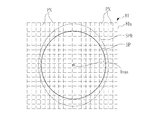
- the image sensor 81a of the beam profiler 81 is inserted at the position of the optical axis of the pulse laser beam PL, and the light intensity I in the cross section SP of the beam is detected by the image sensor 81a. Measured by
- the image sensor 81a has a light receiving surface in which a plurality of pixels PX are two-dimensionally arrayed, and an electric signal representing the light intensity I of the pulse laser light PL to be received is Output.
- a charge coupled device (CCD) image sensor or a complementary metal oxide semiconductor (CMOS) image sensor is used as the image sensor 81a.
- the light intensity I output for each pixel PX is plotted along the radial direction of the cross section SP of the beam, which is a beam profile shown in FIG. 8 and FIG.
- the area of the cross section SP is more precisely the area of the portion where the light intensity I equal to or higher than the threshold Ith is detected in the total cross section SP0 of the beam.
- the threshold value Ith is a value that is 1 / e 2 with respect to the maximum value of the light intensity I output from each pixel PX.
- the target fluence Ft (J / cm 2 ) is the average fluence within the cross section SP of the beam at the transfer position FP. That is, the target fluence Ft corresponds to a value calculated based on the average light intensity Iavs in the whole area of the cross section SP of the beam at the transfer position FP.
- the maximum fluence Fsfp is the maximum of the fluences obtained by dividing the cross section SP of the beam of pulsed laser light on the surface 41 a of the workpiece 41 into a plurality of small areas and obtained for each divided small area. It is a value. That is, the maximum fluence Fsfp is a value determined based on the maximum value among the light intensities I of the plurality of small regions in the cross section SP of the beam on the surface 41a.
- Each small area is an area of one pixel PX of the image sensor 81a in this example.
- the maximum fluence Fsfp is calculated based on the maximum value of the light intensity I detected for each pixel PX.
- the diameter Di of the cross section SP at the transfer position FP is 10 ⁇ m to 150 ⁇ m.
- the size of the pixel PX depends on the resolution of the image sensor 81a.
- the size of the pixel PX is, for example, about 4 ⁇ m square.
- the resolution of the image sensor 81a is preferably 4 ⁇ m to 50 ⁇ m.
- an area obtained by summing a plurality of pixels PX such as an area obtained by summing four adjacent pixels PX, is regarded as one small area, and the light intensity I detected for each small area
- the maximum fluence Fsfp may be calculated based on the maximum value of.
- the resolution of the image sensor 81a is relatively low, such as when the size of one pixel PX of the image sensor 81a is larger than about 4 ⁇ m, the beam of pulsed laser light is expanded in measuring the beam profile.
- the transferred image may be formed on the image sensor 81a. In this way, even when the resolution of the image sensor 81a is relatively low, the resolution of the beam profile of the pulsed laser light PL can be increased.
- the resolution of the beam profile in this case is also preferably the resolution of 4 ⁇ m to 50 ⁇ m described above.
- the light intensity I in the cross section SP shows the maximum light intensity Imax at the center of the cross section SP, but has substantially the same value over the entire cross section SP. Therefore, the average light intensity Iavs in the cross section SP and the maximum light intensity Imax have substantially the same value.
- the light intensity I in the cross section SP shows the maximum light intensity Imax at the center of the cross section SP, and in the periphery thereof compared to the top hat type. I am deeply depressed. Therefore, the average light intensity Iavs in the cross section SP is smaller than the maximum light intensity Imax, and the difference between the average light intensity Iavs and the maximum light intensity Imax is large.
- the ratio of the maximum light intensity Imax to the average light intensity Iavs at the reference position is defined as a light intensity ratio R as shown in the following equation (4).
- R Imax / Iavs (4)
- the light intensity ratio R is, for example, about 1.
- the light intensity ratio R has, for example, a value of about 2 or more.
- the reference position is the transfer position FP in this example
- the average light intensity Iavs is the average light intensity Iavs in the cross section SP at the transfer position FP.
- the maximum light intensity Imax is the maximum light intensity Imax indicated in the beam profile of each position in the optical axis direction of the pulsed laser light PL. That is, in this example, as shown later using FIG. 13 and FIG. 14, the light intensity ratio R is the maximum light intensity Imax at each position in the optical axis direction based on the average light intensity Iavs at the transfer position FP. This is a value indicating how large the average light intensity Iavs is.
- the area of the cross section SP of the beam of pulsed laser light changes depending on the position in the Z-axis direction.
- the luminous flux of the pulsed laser light PL when using the transfer lens 48 is exactly as shown in FIG. 11 and FIG. That is, the luminous flux of the pulse laser light PL emitted from the window 42 is once condensed at the condensing point CP and then diverged to form a transfer image at the transfer position FP.
- the area of the cross section SP of the beam decreases from the transfer position FP to the condensing point CP.
- FIG. 11 is an example in which the depth ⁇ Zsf is 0 mm, and the transfer position FP and the surface 41 a of the workpiece 41 coincide with each other.
- the light intensity ratio R at the transfer position FP is about 1, the target fluence Ft at the transfer position FP and the maximum fluence Fsfp at the surface 41a substantially match.
- FIG. 12 is an example in which the depth ⁇ Zsf is, for example, 1 mm, and the transfer position FP is inward from the surface 41a.
- the transfer position FP is inward from the surface 41a.
- the maximum fluence Ft at the transfer position FP and the maximum fluence Fsfp at the surface 41a do not match.
- the beam profile of the cross section SP of the beam changes in the direction of the optical axis of the pulsed laser beam PL. Therefore, the maximum light intensity Imax does not coincide with the maximum light intensity Imax of the transfer position FP as the reference position and the maximum light intensity Imax of the surface 41a, and the light intensity ratio R changes.
- FIG. 13 shows data obtained by measuring the shape of the cross section SP of the beam and the light intensity distribution at each position in the optical axis direction of the pulsed laser light PL.
- the distance ZL is a distance in the optical axis direction (Z-axis direction) based on the transfer position FP, and the direction from the transfer position FP toward the window 42 and the transfer lens 48 is positive.
- the shape of the cross section SP of the beam and the light intensity distribution are shown.
- FIG. 13A shows a distance ZL
- 13D to 13A are cross sections SP existing between the transfer position FP and the focusing point CP.
- the light intensity distribution is indicated by the change in density in the cross section SP, and the larger the difference in density, the larger the difference in light intensity I. It can be seen from FIG. 13 that the concentration difference between the central portion and the periphery in the cross section SP at each distance ZL is larger as it goes from FIG. 13E to FIG. 13A.
- the shape of the cross section SP of the beam is circular according to the shape of the pinhole of the transfer mask 47, and the light intensity distribution in the cross section SP has a substantially flat top hat shape. doing.
- the shape of the cross section SP approaches an ellipse, and the radial beam profile of the cross section SP also has a large difference between the center and the periphery. It is approaching distribution.
- the beam profile of the cross section SP changes in the optical axis direction of the pulse laser beam PL.
- the light intensity ratio R also changes according to the distance ZL.
- FIG. 14 shows correlation data between the distance ZL and the light intensity ratio R, which is generated from the measurement data shown in FIG.
- the light intensity ratio R indicates the magnitude of the maximum light intensity Imax at each position as shown in FIG. 13E to FIG. 13A with respect to the average light intensity Iavs at the transfer position FP which is the reference position. It is a value.
- the light intensity ratio R is approximately 1 as shown in the graph of FIG.
- the distance ZL is from 0 to 1.5 mm, ie, from the transfer position FP to the condensing point CP
- the light intensity ratios R 1.5, 2 and 2.5, respectively.
- the beam profile of the cross section SP approaches a shape such as Gaussian distribution, and as a result, the maximum light intensity Imax at each distance ZL is relative to the average light intensity Iavs at the transfer position FP. It shows that it is getting bigger.
- the transfer position FP when the transfer position FP is set to the surface 41a, if the beam profile is, for example, a top hat type as shown in FIG. 8, the target fluence Ft at the transfer position FP and the surface 41a.
- the maximum fluence Fsfp at the surface 41a is obtained from the relationship between the distance ZL and the light intensity ratio R shown in FIG. Indicates a value larger than the target fluence Ft at the transfer position FP.
- the maximum fluence Fsfp on the surface 41 a of the workpiece 41 can be obtained from the light intensity ratio R and the target fluence Ft at the transfer position FP according to the following equation.
- Fsfp R ⁇ Ft (5)
- the light intensity ratio R 2.
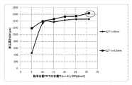
- FIG. 15 is a graph showing the relationship between the target fluence Ft at the transfer position FP and the processing depth ⁇ Zd.
- the horizontal axis is the target fluence Ft, and the vertical axis is the processing depth ⁇ Zd.
- the target fluence Ft is changed from 5 J / cm 2 to 30 J / cm 2 .
- the target fluence Ft is in the range of 10 J / cm 2 to 30 J / cm 2 .
- holes with a high aspect ratio such as a machining depth ⁇ Zd of 1 mm or more can be formed. In the range of this target fluence Ft, no crack CR has occurred.
- the other irradiation conditions are the same as in FIG.
- the light intensity ratio R is approximately 1 according to the graph of FIG. Therefore, when the target fluence Ft at the transfer position FP is 30 J / cm 2 , the maximum fluence Fsfp is also unchanged at about 30 J / cm 2 .
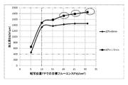
- FIG. 18 and 19 also show graphs of experimental results similar to FIG. Also in FIG. 18 and FIG. 19, the graph of FIG. 15 is also inserted so that it can be compared with the graph of FIG.
- FIG. 18 shows an example in the case where the depth ⁇ Zfs is set to 1 mm.
- FIG. 19 shows an example in which the depth ⁇ Z fs is 1.5 mm.
- the crack CR occurs in the target fluence Ft in the range of 20 J / cm 2 to 30 J / cm 2 .
- the light intensity ratio R is about 2 according to the graph of FIG. Therefore, when the target fluence Ft of the transfer position FP is 20 J / cm 2 , the maximum fluence Fsfp is about 40 J / cm 2 . Similarly, when the target fluence Ft is 30 J / cm 2 , the maximum fluence Fsfp is about 60 J / cm 2 .
- the light intensity ratio R is about 2.5. Therefore, even if the target fluence Ft of the transfer position FP is 20 J / cm 2 , the maximum fluence Fsfp is about 50 J / cm 2 . Similarly, when the target fluence Ft is 30 J / cm 2 , the maximum fluence Fsfp is about 75 J / cm 2 .
- data of conditions 3-1 to conditions 3-3 are data corresponding to the experimental result shown in the graph of FIG. That is, data for condition 3-3
- the maximum fluence Fsfp at the surface 41a is 40 J /, as indicated by the conditions in which the cells are grayed out, as the conditions 2-3, 3-2, 3-3, 4-2, and 4-3.
- cm 2 or more it can be seen that the crack CR is generated.
- the inventors have found from these experimental results that the maximum fluence Fsfp is considered to be the cause of the crack CR.
- FIG. 22 schematically illustrates the configuration of a laser processing system 2A according to the first embodiment.
- the laser processing system 2A of the first embodiment includes a laser processing apparatus 4A in place of the laser processing apparatus 4 of the laser processing system 2 of the comparative example described with reference to FIG.
- differences from the laser processing system 2 of the comparative example will be mainly described, and the same components will be assigned the same reference numerals and descriptions thereof will be omitted.
- the laser processing apparatus 4A of the first embodiment includes a laser processing control unit 32A instead of the laser processing control unit 32.
- the other configuration of the laser processing apparatus 4A is the same as that of the laser processing apparatus 4 of the comparative example.
- the laser processing control unit 32A differs from the laser processing control unit 32 of the comparative example in that the surface of the workpiece 41 is set based on the target fluence Ft at the transfer position FP, which is set as an irradiation condition prior to laser processing. It is a point that a process of determining whether or not the maximum fluence Fsfp in 41a is within a predetermined range is added. The other points are similar to those of the laser processing control unit 32A.
- FIG. 23 of the first embodiment differs from the flowchart of FIG. 3 of the comparative example in that steps S1410 and S1420 are added between steps S1400 and S1500. Also, the difference is that S1900 is added. The other points are the same.
- the laser processing control unit 32A of the first embodiment executes the processing of S1100 to S1400 as in the comparative example. Thereafter, the processes of S1410 and S1420 are executed.
- S1410 is a process of evaluating the maximum fluence Fsfp of the surface 41a of the workpiece 41.
- S1420 is processing to determine whether or not the maximum fluence Fsfp is within the allowable range based on the evaluation result of S1410.
- the data of the allowable range is stored in advance in, for example, a memory in the laser processing controller 32A, an external storage, or the like.
- the laser processing control unit 32A proceeds to S1500.
- the subsequent processing is the same as that of the comparative example.
- the laser processing control unit 32A functions as a determination unit that determines whether or not the maximum fluence Fsfp of the pulse laser light PL on the surface 41a of the workpiece 41 which is a transparent material is within a predetermined allowable range. Furthermore, the laser processing control unit 32A functions as a control unit that permits the irradiation of the pulsed laser light PL when the maximum fluence Fsfp is determined to be within the predetermined allowable range.
- the laser processing control unit 32A proceeds to S1900 and issues a warning.
- the content of the warning is a content to notify that the laser processing can not be performed because the crack CR may occur under the set irradiation condition.
- the laser processing control unit 32A controls a display (not shown) to notify the user of such a content message.
- the speaker may be controlled to notify a message by voice.
- a warning message may be notified to a factory management system that manages the inside of the factory.
- FIG. 24 is a flowchart showing a processing procedure for evaluating the maximum fluence Fsfp in S1410.
- the laser processing control unit 32A reads the value of the depth ⁇ Zsf from the data of the irradiation condition, and sets the read ⁇ Zsf as the distance ZL in the memory (S1411).
- the laser processing control unit 32A reads the light intensity ratio R corresponding to the irradiation condition from the correlation data between the distance ZL and the light intensity ratio R shown in FIG. Specifically, the light intensity ratio R corresponding to the distance ZL in which the value of the depth ⁇ Zsf is set in S1411 is read (S1412).
- the correlation data shown in FIG. 14 is stored in advance in the memory or the external storage of the laser processing control unit 32A.
- the correlation data may be recorded in the form of a table or may be recorded in the form of a function.
- the laser processing control unit 32A calculates the maximum fluence Fsfp at the surface 41a of the workpiece 41 based on the equation (5) described above from the target fluence Ft at the transfer position FP based on the read light intensity ratio R. (S1413).
- the laser processing control unit 32A When it is determined in S1414 that the maximum fluence Fsfp is within the allowable range, the laser processing control unit 32A records “0” in the flag FRG as an evaluation result (S1415). When it is determined at S1414 that the maximum fluence Fsfp is out of the allowable range, the laser processing control unit 32A records “1” in the flag FRG as an evaluation result (S1416). Thereafter, the laser processing control unit 32A returns to the main routine shown in FIG. 23, and executes S1420.
- the laser processing system 2A determines that the maximum fluence Fsfp is within the allowable range in the laser processing that applies the pulsed laser light PL to perform hole processing with a high aspect ratio. In this case, irradiation of pulsed laser light is permitted. Therefore, the occurrence of the crack CR can be suppressed.
- the laser processing system 2A gives a warning when it is determined that the maximum fluence Fsfp is out of the allowable range. Therefore, the user can surely grasp that the irradiation condition is inappropriate. Further, the laser processing system 2A prohibits laser processing when it is determined that the maximum fluence Fsfp is out of the allowable range. Therefore, the occurrence of the crack CR can be prevented in advance.
- the laser processing control unit 32A automatically changes the irradiation condition to an appropriate one that does not have the possibility of the occurrence of the crack CR, and performs the laser processing. May be
- Pulse Width of Pulsed Laser Light When using ultraviolet pulsed laser light, use a pulsed laser light on the order of 1 ns to 100 ns with a full-width half-maximum pulse width. Is desired. The pulse width is determined by the performance of the laser device 3, but at this moment, the laser device 3 capable of outputting a pulse laser beam of high pulse energy in picosecond pulse width as an ultraviolet pulse laser beam is manufactured. Because it is difficult. As in this example, by using a pulsed laser beam of ultraviolet light on the order of nanoseconds, it is possible to use the laser device 3 readily available at the present time.
- the preferable pulse width is 1 ns to 100 ns in full width at half maximum, and more preferably 10 ns to 20 ns.
- the laser device 3 it is preferable to use the laser device 3 that outputs pulsed laser light of such pulse width.
- Preferred processing in the case of applying high aspect ratio holes to a workpiece 41 which is a transparent material transparent to ultraviolet light such as synthetic quartz glass, using pulsed laser light of ultraviolet light on the order of nanoseconds The conditions are as follows.
- the range of diameter Di of the beam at the transfer position FP of the pulse laser light PL is preferably 10 ⁇ m or more and 150 ⁇ m or less.
- the phenomenon as shown in FIG. 5 occurs when the range of the diameter Di is 10 ⁇ m or more and 150 ⁇ m or less. This is because such a phenomenon is a prerequisite for realizing high aspect ratio drilling.
- central wavelength of pulsed laser light Is preferably 157.6 nm to 248.7 nm.
- the pulsed laser light is preferably ArF laser light having a center wavelength of about 193.4 nm.
- the range of depth ⁇ Zsf is preferably 0 mm or more and 4 mm or less. It is clear from the experimental results that the machining depth ⁇ Zd becomes larger as the depth ⁇ Zsf becomes deeper up to a certain value. However, if the depth ⁇ Zsf exceeds about 4 mm, the machining depth ⁇ Zd largely interrupts 1 mm, and it becomes impossible to drill holes with a high aspect ratio. This is because when the transfer position FP is too deep, the fluence near the surface 41 a of the workpiece 41 is insufficient and the ablation processing near the surface does not proceed, and as a result, the ablation processing does not proceed in the depth direction It is thought that it is for.
- the target fluence Ft is preferably 5 J / cm 2 or more and 30 J / cm 2 or less. It is known that when the target fluence Ft is less than 5 J / cm 2 , high aspect ratio holes can not be machined as shown in FIG. That is, the lower limit value of the preferable range of the target fluence Ft is 5 J / cm 2 . Further, as shown in FIG. 16 to FIG. 21, in the range of depth ⁇ Z fs of 0.5 mm or more and 1.5 mm or less of the transfer position FP, when the target fluence Ft exceeds 30 J / cm 2 , generation of cracks CR Are concerned. Therefore, the upper limit of the preferable range of the target fluence Ft is 30 J / cm 2 .
- the allowable range of maximum fluence Fsfp is preferably 10 J / cm 2 or more and 40 J / cm 2 or less based on the experimental results shown in FIGS. In the allowable range, a value of 10J / cm 2 of a lower limit is 5 J / cm 2 is the basis for the lower limit of the target fluence Ft required for drilling with a high aspect ratio.
- the maximum value of the light intensity ratio R is 2 or more depending on the value of the distance ZL. Therefore, if 5 J / cm 2 which is the lower limit value of the target fluence Ft is multiplied by “2” as a value estimated by reducing the maximum value of the light intensity ratio R, it becomes 10 J / cm 2 . That is, 5 J / cm 2 as a target fluence Ft is minimum required to realize high aspect ratio hole machining, and when the light intensity ratio is 2 or more, the maximum fluence Fsfp is 10 J / cm 2 or more. This is the basis for setting the lower limit value of the maximum fluence Fsfp to 10 J / cm 2 .
- FIG. 25 is a graph showing the relationship between the irradiation pulse number N and the processing depth ⁇ Zd. All six graphs shown in FIG. 25 are graphs in the case where the depth ⁇ Zdsf of the transfer position FP is 0.5 mm. The differences between the graphs are the values of the target fluence Ft and the maximum fluence Fsfp. FIG. 25 shows how the processing depth ⁇ Zd changes when the irradiation pulse number N is changed from 5,000 pulses to 30,000 pulses. Further, as other irradiation conditions common to each graph, the irradiation time is 5 seconds to 30 seconds, the diameter Di of the cross section SP of the beam is 55 ⁇ m, and the repetition frequency f is 1 kHz.
- the processing depth is ⁇ Zd increases from about 1 mm (1,000 ⁇ m) to about 5 mm (5,000 ⁇ m).
- the processing depth ⁇ Zd is saturated when the irradiation pulse number N is 20,000 pulses, and does not increase even if the irradiation pulse number N is increased more than that.
- the irradiation pulse number N is 5,000 to 20,000 pulses, it is possible to drill a hole having a processing depth ⁇ Zd of 5 mm (5,000 ⁇ m) at maximum.
- the irradiation pulse number N is preferably in the range of 5,000 pulses to 20,000 pulses.
- the relative positioning between the transfer position FP of the pulse laser beam PL and the workpiece 41 is performed by moving the workpiece 41 by controlling the XYZ stage 34. .
- relative positioning may be performed by moving the transfer mask 47 in the optical axis direction of the pulse laser beam. That is, moving the transfer mask 47 in the direction of the optical axis of the pulse laser beam PL is equivalent to changing the position on the object side of the transfer image transferred by the transfer lens 48 with respect to the transfer lens 48.
- the image transfer position also changes in the optical axis direction. As a result, relative positioning between the transfer position FP of the pulse laser beam PL and the workpiece 41 becomes possible.
- the size of the transferred image also changes.
- the diameter of the pinhole of the transfer mask 47 may be changed so that the change of the diameter of the transfer image resulting from the movement of the transfer mask 47 is suppressed.
- the pulse laser beam is simply collected as in the second embodiment to be described later.
- the transfer mask 47 forms a pinhole-shaped transfer image of the pulse laser beam, instead of irradiating the workpiece 41 with the beam of the pulse laser beam as it is.
- the formed transfer image is transferred to the workpiece 41. Therefore, the change of the diameter of the beam resulting from the mode change of the pulsed laser light is suppressed.
- ArF laser gas is used as the laser medium as the laser device 3 and an ArF excimer laser device that outputs pulsed laser light having a central wavelength of about 193.4 nm is described as an example, other laser devices may be used.
- a KrF laser gas may be used as a laser medium, and a KrF excimer laser device that outputs pulsed laser light having a center wavelength of about 248.4 nm may be used.
- synthetic quartz glass is used as the workpiece 41, the range of the central wavelength of the pulsed laser light is from about 157.6 nm, which is the central wavelength of the F 2 laser, to 248.4 mn, which is the central wavelength of the KrF laser. Is preferred.
- the synthetic quartz glass is exemplified as the workpiece 41.
- the present invention is not limited to the synthetic quartz glass, and the workpiece 41 may be a transparent material transparent to ultraviolet pulse laser light.
- a transparent material transparent to ultraviolet pulse laser light there are MgF 2 crystal, CaF 2 crystal, sapphire, quartz crystal and the like.
- FIG. 26 shows a laser processing system 2B of a second embodiment.
- the laser processing system 2B of the second embodiment includes the laser device 3 and a laser processing device 4B.
- the laser device 3 is the same as that of the first embodiment.
- the laser processing apparatus 4B includes an optical system 61 in place of the optical system 36 of the laser processing apparatus 4A of the first embodiment.
- the optical system 61 does not include the transfer mask 47 and the transfer lens 48 like the optical system 36 of the first embodiment, and condenses the beam of pulsed laser light having Gaussian distribution output from the laser device 3 as it is. This is an optical system provided with a condensing optical system for irradiating the workpiece 41.
- the laser processing control unit 32B performs the relative positioning between the transfer position of the pulsed laser light and the workpiece 41 as in the laser processing control unit 32A of the first embodiment, but the beam waist position of the pulsed laser light PL. Relative positioning of the BW and the workpiece 41 is performed.
- the depth ⁇ Zsfw in the second embodiment is not the depth ⁇ Zsf of the transfer position FP but the depth of the beam waist position.
- the target fluence Ftw in the second embodiment is not the target fluence Ft at the transfer position FP but the target fluence at the beam waist position BW.
- the laser processing control unit 32B determines whether or not the maximum fluence Fsfp on the surface 41a of the workpiece 41 is within the allowable range based on the target fluence Ftw at the beam waist position BW.
- the other configuration of the laser processing system 2B is the same as that of the laser processing system 2A of the first embodiment, and therefore, differences will be mainly described below.
- the optical system 61 includes high reflection mirrors 36 a to 36 c, an attenuator 52, and a condenser lens 62.
- the high reflection mirrors 36a to 36c and the attenuator 52 are the same as the optical system 36 of the first embodiment.
- the high reflection mirror 36 c reflects the pulse laser light toward the focusing lens 62.
- the condensing lens 62 is disposed to condense the incident pulse laser light onto the workpiece 41 via the window 42.
- the laser processing system 2B of the second embodiment also processes a hole with a high aspect ratio of 10 ⁇ m to 150 ⁇ m in the processing diameter to the workpiece 41, similarly to the laser processing system 2A of the first embodiment. . Therefore, the laser processing system 2B also irradiates the workpiece 41 with pulsed laser light having a beam diameter Dw of 10 ⁇ m or more and 150 ⁇ m or less at the beam waist position BW.
- the diameter Dw of the beam of the pulsed laser light PL at the beam waist position is, like the diameter Di shown in FIG. 9, the width of the position where the value of 1 / e 2 with respect to the maximum light intensity Imax is 1 / E 2 full width.
- the pulsed laser light PL of Gaussian distribution is irradiated to the workpiece 41 without being converted to a transfer image. Therefore, the diameter of the beam of the pulsed laser light PL is determined by the specification of the laser device 3.
- the fluence Fw at the beam waist position BW can be obtained from the following equation (6).
- Fw Et ⁇ T / ⁇ (Dw / 2) 2 ⁇ (6)
- T transmittance of the attenuator
- Et pulse energy of pulse laser light output from the laser device
- Dw diameter of the cross section SP of the beam at the beam waist position BW.
- the transmittance T of the attenuator can be determined by the following equation (7) from the above equation (6) when there is no light loss of the optical system 36.
- T ⁇ (Dw / 2) 2 ⁇ Fw / Et (7)
- the light beam of the pulsed laser light PL of the second embodiment is most narrowed at the beam waist position BW after exiting the condensing lens 62, and then diverges.
- the diameter of the cross section SP of the beam is minimized at the beam waist position BW.
- the diameter and area of the cross section SP of the beam at the surface 41a are the diameter of the cross section SP of the beam at the beam waist position BW and Larger than the area.
- the pulsed laser light PL when using a focusing optical system has such characteristics. Therefore, in the second embodiment, assuming that the value corresponding to the distance ZL in the first embodiment is the distance ZLw from the beam waist position BW to the surface 41a, the relationship between the light intensity ratio Rw and the distance ZLw is shown in FIG. It becomes such a relationship.
- the light intensity ratio Rw is a light intensity ratio in the case where the pulsed laser light PL is condensed by the condenser lens 42 and irradiated to the workpiece 41 as in the second embodiment, and the beam waist position BW Is a light intensity ratio when the beam profile at is close to the Gaussian distribution.
- the light intensity ratio Rw can be obtained from the following equation (8).
- Rw Imax / Iavw (8)
- Iavw is the average light intensity at the beam waist position BW
- the average light intensity Imax is the maximum light intensity Imax at each position at a distance ZLw from the beam waist position BW.
- the maximum fluence Fsfp on the surface 41 a of the workpiece 41 can be obtained from the light intensity ratio Rw and the target fluence Ft at the transfer position FP according to the following equation (9).
- Fsfp Rw ⁇ Ftw (9)
- the distance ZLw 0, that is, the light intensity ratio Rw when the beam waist position BW coincides with the surface 41a is maximized, and the light intensity ratio Rw decreases as the distance ZLw increases.
- the laser processing control unit 32B uses the data of the correlation between the distance ZLw and the light intensity ratio Rw shown in FIG. 29 such that the maximum fluence Fsfp of the surface 41a of the workpiece 41 is within the allowable range. It is determined whether or not it is inside.
- step S1400 is changed to step S1400B
- step S1410 is changed to S1410B
- S1500 and S1600 are changed to S1500B and S1600B, respectively.
- the other points are the same.
- the laser processing control unit 32B executes S1400B after executing S1100 to S1300.
- the laser processing control unit 32B acquires the irradiation condition of the pulse laser beam.
- the irradiation conditions include the target fluence Ftw at the beam waist position BW, the depth ⁇ Z fsw of the beam waist position BW, the number N of irradiation pulses, and the repetition frequency f.
- S1410B is a process of evaluating the maximum fluence Fsfp of the surface 41a of the workpiece 41.
- S1420 is processing to determine whether or not the maximum fluence Fsfp is within the allowable range based on the evaluation result of S1410B.
- the laser processing control unit 32B determines that the maximum fluence Fsfp is within the allowable range in S1420 (Y in S1420)
- the processing proceeds to S1500B.
- the laser processing control unit 32B executes the process of S1600B.
- the subsequent processes in the main flowchart are the same as in the first embodiment.
- FIG. 32 is a flowchart showing a processing procedure of evaluating the maximum fluence Fsfp in S1410B.
- the difference between FIG. 24 and the first embodiment is that S1411 to S1413 are changed from S1411B to S1413B.
- the laser processing control unit 32B reads the value of the depth ⁇ Zsfw from the data of the irradiation conditions, and sets the read ⁇ Zsfw as the distance ZLw.
- the laser processing control unit 32A reads the light intensity ratio Rw corresponding to the irradiation condition from the correlation data of the distance ZLw and the light intensity ratio Rw illustrated in FIG. Specifically, the light intensity ratio Rw corresponding to the distance ZLw in which the value of the depth ⁇ Zsfw is set in S1411B is read (S1412B).
- the laser processing control unit 32B calculates the maximum fluence Fsfp at the surface 41a of the workpiece 41 from the target fluence Ftw at the beam waist position BW based on the equation (9) described above based on the read light intensity ratio Rw. (S1413B). In the subroutine of FIG. 31, the subsequent processing is the same as that of the first embodiment.
- FIG. 32 shows a processing procedure of laser processing of S1600B.
- the difference between FIG. 4 and the comparative example is that S1604 is changed to S1604B.
- the laser processing control unit 32B sets the transmittance T of the attenuator 52 such that the fluence Fw at the beam waist position BW of the pulse laser light PL becomes the target fluence Ftw of the irradiation condition.
- the other processes are the same as in FIG.
- the laser processing system 2B of the second embodiment permits the irradiation of pulsed laser light when the maximum fluence Fsfp is determined to be within the allowable range. Therefore, the occurrence of the crack CR can be suppressed. Further, in the second embodiment using the condensing optical system, the utilization efficiency of the pulse laser beam PL is higher than that in the first embodiment using the transfer lens 48. Therefore, in the second embodiment, when the same material is drilled to the same size, the pulse energy of the pulsed laser light PL output from the laser device 3 is lowered compared to the first embodiment. be able to. In the second embodiment, other effects and preferable processing conditions are also the same as in the first embodiment.
- the resonator of the laser device 3 is a Fabry-Perot resonator and may be an unstable resonator.
- the unstable resonator is a resonator in which the partial reflection surface of the output coupling mirror 27 is a convex surface and the high reflection surface of the rear mirror 26 is a concave surface.
- FIG. 33 shows a laser processing system 2C of a third embodiment.
- a laser processing system 2C of the third embodiment includes a laser device 3 and a laser processing device 4C.
- the laser device 3 is the same as that of the first embodiment.
- the laser processing apparatus 4C includes a beam profiler 81 in addition to the configuration of the laser processing apparatus 4A of the first embodiment.
- the laser processing apparatus 4C includes a laser processing control unit 32C in place of the laser processing control unit 32A of the laser processing apparatus 4A.
- the laser processing control section 32C has a function of controlling the beam profiler 81 to obtain data indicating the correlation between the distance ZL and the light intensity ratio R shown in FIG. There is.
- the third embodiment is the same as the first embodiment in the other points. The differences will be mainly described below.
- the beam profiler 81 is provided at the end of the table 33.
- the beam profiler 81 includes an image sensor 81a, a bracket 81b, and a uniaxial stage 81c.
- the image sensor 81a is attached to one end of the bracket 81b, and the other end is attached to the uniaxial stage 81c.
- the 1-axis stage 81 c moves the image sensor 81 a in the Y-axis direction. Specifically, the uniaxial stage 81c moves between an insertion position at which the image sensor 81a is inserted at the position of the optical axis of the pulse laser light PL emitted from the transfer lens 48 and a retraction position at which the image sensor 81a retracts from the insertion position. Do.
- the retracted position is a position where there is no problem in performing the laser processing on the workpiece 41 on the table 33.
- the position of the image sensor 81 a in the Z-axis direction can be adjusted by the XYZ stage 34.
- the beam profiler 81 is provided with an ND filter (not shown). The ND filter attenuates the pulsed laser light incident on the light receiving surface of the image sensor 81a.
- the laser processing procedure of the third embodiment is substantially the same as FIGS. 23 and 24 in the first embodiment. The difference is that the process of S1000 shown in FIG. 34 is added before S1100 in the flowchart of FIG.
- S1000 shown in FIG. 34 is acquisition processing of correlation data between the distance ZL and the light intensity ratio R.
- the laser processing control unit 32C controls the uniaxial stage 81c to insert the image sensor 81a of the beam profiler 81 at the optical axis position of the pulse laser beam PL.
- the laser processing control unit 32C controls the XYZ stage 34 to align the position of the image sensor 81a in the Z-axis direction with the transfer position FP of the pulse laser beam. This position is a position where the distance ZL coincides with the light receiving surface of the image sensor 81a. Therefore, the laser processing control unit 32C sets the value of the distance ZL on the memory to the initial value "0".
- the laser processing control unit 32C causes the laser device 3 to perform laser oscillation by transmitting a control signal to cause laser oscillation under typical conditions to the laser control unit 13 (S1020).
- the typical condition is, for example, a rated value of the laser device 3.
- the target pulse energy Et is in the range of 40 mJ to 200 mJ
- the repetition frequency f is in the range of 10 Hz to 6 kHz. If processing conditions for laser processing are known at this time, laser oscillation may be performed by setting the target pulse energy Et and the repetition frequency f defined as the processing conditions.
- the laser processing control unit 32C causes the laser device 3 to output the pulsed laser beam PL, and the image sensor 81a receives the pulsed laser beam PL to measure the beam profile.
- the maximum light intensity Imax and the average light intensity Iavs of the pulsed laser light are calculated based on the measured beam profile.
- the laser processing controller 32C records the calculated value of the light intensity ratio R in the memory in relation to the value of the distance ZL (S1045).
- the laser processing controller 32C moves the position of the image sensor 81a in the Z-axis direction upward by ⁇ ds (S1050). Along with this, the laser processing control unit 32C adds ⁇ ds to the value of the distance ZL on the memory. The movement interval of the image sensor 81a in the Z-axis direction. That is, the laser processing control unit 32C measures the light intensity ratio R at intervals of ⁇ ds.
- the value of ⁇ ds is, for example, 100 ⁇ m.
- the laser processing control unit 32C determines whether the distance ZL has exceeded the upper limit value Zmax.
- the upper limit value Zmax is, for example, 1.5 mm. If the distance ZL is equal to or less than the upper limit Zmax (N in S1055), the laser processing controller 32C proceeds to S1070.
- S1070 is a process of measuring the beam profile at the distance ZL set in S1050 and calculating the maximum light intensity Imax.
- the laser processing control unit 32C repeats the processes of S1040 to S1050 described above.
- data of the light intensity ratio R is recorded at an interval ⁇ ds.
- the laser processing control unit 32C ends the measurement and stops the laser oscillation (S1060). Then, the laser processing control unit 32C moves the image sensor 81a of the beam profiler 81 to the retracted position (S1065).
- the laser processing control unit 32C generates correlation data of the distance ZL and the light intensity ratio R as shown in FIG. 14 based on the recorded data of the light intensity ratio R at the ⁇ ds interval recorded.
- the laser processing control unit 32C stores the generated correlation data in a memory or an external storage.
- the correlation data may be recorded in the form of a table, or may be recorded in the form of a function by obtaining an approximate expression from data of a plurality of light intensity ratios R recorded every ⁇ ds. Alternatively, the data may be interpolated based on the light intensity ratio R recorded for each ⁇ ds.
- the laser processing control unit 32C proceeds to S1100 in FIG. The subsequent processing is the same as that of the first embodiment.
- the flowchart of FIG. 35 shows the procedure for calculating the maximum light intensity Imax and the average light intensity Iavs in S1030.
- the process of S1030 is the same as the contents schematically described in FIG. 8 to FIG.
- the average light intensity Iavs at the transfer position FP and the maximum light intensity Imax at the transfer position FP are calculated.
- the laser processing control unit 32C calculates an average light intensity Iavs which is an average value of the light intensity I of the pixel PX having a value equal to or more than the threshold Ith (S1034).
- the flowchart of FIG. 36 shows a processing procedure of the calculation of the maximum light intensity Imax in S1070. Unlike the process of S1030 shown in FIG. 35, in the process of S1070, the average light intensity is not calculated, and the maximum light intensity Imax at the position of the distance ZL after moving from the transfer position FP is calculated.
- the process of S1070 is the same as the first half of FIG. 35, and there is no step of calculating the average light intensity of the second half. That is, in S1071, first, the laser processing control unit 32C measures the beam profile by the image sensor. Next, among the light intensities I of the respective pixels PX of the image sensor 81, the maximum light intensity Imax which is the maximum value is obtained (S1072).
- the beam profiler 81 is used to measure correlation data between the distance ZL and the light intensity ratio R. Therefore, it is possible to acquire correlation data reflecting individual differences of the laser processing system 2C, such as characteristics of the optical system 36, for example. Therefore, the calculation accuracy of the maximum fluence Fsfp is improved.
- the pulse laser beam incident on the image sensor 81a is attenuated by the ND filter.
- the transmittance T of the attenuator 52 is controlled to control the energy of the pulse laser beam incident on the image sensor 81a. May be lowered.
- the transmittance T of the attenuator 52 is fixed while acquiring the correlation data. If the transmittance T fluctuates during acquisition, accurate correlation data can not be acquired.
- the laser processing apparatus 4D shown in FIG. 37 is a modification of the laser processing apparatus 4B of the second embodiment shown in FIG.
- the laser processing apparatus 4D includes an optical system 71 instead of the optical system 61 of the laser processing apparatus 4B. Further, instead of the laser processing control unit 32B, a laser processing control unit 32D is provided.
- the other configuration is the same. The differences will be mainly described below.
- the optical system 71 is obtained by adding a wave front adjuster 72 to the optical system 61.
- the wavefront tuning unit 72 includes a concave lens 72a, a convex lens 72b, and a uniaxial stage 72c.
- the uniaxial stage 72c holds the concave lens 72a, and moves the concave lens 72a in the optical axis direction to adjust the distance between the concave lens 72a and the convex lens 72b.
- the concave lens 72 a and the convex lens 72 b are disposed on the optical path of the pulsed laser light between the high reflection mirror 36 c and the condenser lens 62.
- the pulse laser light reflected by the high reflection mirror 36c is incident on the condenser lens 62 via the concave lens 72a and the convex lens 72b.
- the laser processing control unit 32D controls the XYZ stage 34 to adjust the position of the workpiece 41 in the XY plane.
- the stage 72c is controlled to adjust the position of the beam waist in the Z-axis direction.
- the laser processing control unit 32D controls the uniaxial stage 72c to adjust the distance between the concave lens 72a and the convex lens 72b, thereby changing the wavefront of the pulse laser beam. By controlling the wavefront of this pulse laser beam, the beam waist position BW of the pulse laser beam is adjusted.
- the laser processing system 2E shown in FIG. 38 is obtained by changing the laser processing apparatus 4A of the laser processing system 2A of the first embodiment to a laser processing apparatus 4E.
- the laser processing apparatus 4E includes a beam homogenizer 46.
- the beam homogenizer 46 is disposed upstream of the transfer mask 47 in the optical axis direction of the pulsed laser light.
- the beam homogenizer 46 includes a fly's eye lens 46a and a condenser lens 46b.
- the beam homogenizer 46 is arranged to make the light intensity distribution of the pulsed laser light reflected by the high reflection mirror 36 b uniform so as to illuminate the transfer mask 47 with Koehler.
- the laser processing apparatus 4E includes a laser processing control unit 32E instead of the laser processing control unit 32A.
- the other configuration is the same as that of the first embodiment.
- the fly's-eye lens 46a of the beam homogenizer 46 has a form in which a plurality of small lenses are two-dimensionally arranged. Therefore, in the beam profile of the cross section SP of the beam on the upstream side of the transfer position FP where the transfer image is formed, a plurality of peaks may occur corresponding to each small lens. Even in this case, one top hat has one shape at the transfer position FP.
- the cross section SP of the beam in which a plurality of peaks occur may be closer to the surface 41 a on the upstream side than the transfer position FP. In this case, a plurality of fluence peaks will be present in the cross section SP of the beam on the surface 41a.
- the laser processing control unit 32E determines the peak indicating the maximum value among the peaks as the maximum fluence Fsfp. Then, the laser processing control unit 32E determines whether the maximum fluence Fsfp is within the allowable range. The other processes are the same as in the first embodiment.
- the transfer mask 47 is irradiated with the pulsed laser beam whose light intensity is uniformed, the light intensity distribution at the transfer position FP is uniformized.
- transfer mask 47 a transfer mask in which a plurality of holes are formed may be used. In this case, a plurality of holes can be machined simultaneously on the workpiece 41.
- the laser device can be variously modified.
- a laser device shown in FIG. 39 or 40 may be used as a laser device.
- the laser device 3D of the modified example 1 shown in FIG. 39 is obtained by adding an amplifier 80 to the laser device 3 of the first embodiment, and the other process is substantially the same.
- the amplifier 80 is disposed on the optical path of the pulsed laser light between the master oscillator 10 and the monitor module 11.
- the amplifier 80 is an amplifier that amplifies the energy of pulsed laser light output from the master oscillator 10.
- the basic configuration of the amplifier 80 is the same as that of the master oscillator 10, and includes the laser chamber 21, the charger 23, and the pulse power module (PPM) 24 like the master oscillator 10.
- PPM pulse power module
- the laser controller 13D controls the charging voltage of the charger 23 to control the pulse energy.
- the laser control unit 13D When receiving the light emission trigger Tr from the laser processing control unit 32A, the laser control unit 13D causes the master oscillator 10 to perform laser oscillation. In addition, the amplifier 80 is controlled to operate in synchronization with the master oscillator 10. The laser control unit 13D turns on the switch 24a of the pulse power module 24 of the amplifier 80 so that discharge occurs when the pulse laser light output from the master oscillator 10 enters the discharge space in the laser chamber 21 of the amplifier 80. Do. As a result, the pulsed laser light incident on the amplifier 80 is amplified in the amplifier 80.
- the pulse laser light amplified and output by the amplifier 80 has its pulse energy measured in the monitor module 11.
- the laser control unit 13D controls the charging voltage of the charger 23 of each of the amplifier 80 and the master oscillator 10 so that the measured values of the measured pulse energy approach the target pulse energy Et.
- the pulse energy of the pulse laser light can be increased.
- the laser device 3E of the modification 2 shown in FIG. 40 may be used.
- the laser device 3E includes a master oscillator 83 and an amplifier 84.
- the laser device 3E includes a monitor module 11E instead of the monitor module 11.
- the monitor module 11E has a wavelength monitor 11c and a beam splitter 11d added to the configuration of the monitor module 11 of the first embodiment.
- the beam splitter 11d is disposed between the optical sensor 11b and the reflected light path of the beam splitter 11a.
- the beam splitter 11d reflects a part of the reflected light reflected by the beam splitter 11a and transmits the rest.
- the transmitted light transmitted through the beam splitter 11d enters the optical sensor 11b, and the reflected light reflected by the beam splitter 11d enters the wavelength monitor 11c.
- the wavelength monitor 11 c is a known etalon spectrometer.
- the etalon spectrometer is constituted of, for example, a diffusion plate, an air gap etalon, a condensing lens, and a line sensor.
- the etalon spectroscope generates interference fringes of the incident laser light by the diffusion plate and the air gap etalon, and focuses the generated interference fringes on the light receiving surface of the line sensor with a condenser lens. Then, the wavelength ⁇ of the laser light is measured by measuring the interference fringes formed on the line sensor.
- the master oscillator 83 is a solid-state laser device, and includes a semiconductor laser 86 that outputs seed light, a titanium-sapphire amplifier 87 that amplifies the seed light, and a wavelength conversion system 88.
- the semiconductor laser 86 is a distributed feedback semiconductor laser that outputs CW (Continuous Wave) laser light, which is laser light that continuously oscillates at a wavelength of 773.6 nm, as seed light. By changing the temperature setting of the semiconductor laser 86, the oscillation wavelength can be changed.
- CW Continuous Wave
- the titanium-sapphire amplifier 87 includes a titanium-sapphire crystal (not shown) and a pulsed laser apparatus (not shown).
- the titanium sapphire crystal is disposed on the light path of the seed light.
- the pumping pulse laser device is a laser device that outputs the second harmonic light of the YLF laser.
- the wavelength conversion system 88 is a wavelength conversion system that generates fourth harmonic light, and includes an LBO (LiB 3 O 5 ) crystal and a KBBF (KBe 2 BO 3 F 2 ) crystal. Each crystal is disposed on a rotating stage (not shown), and is configured to be able to change the incident angle of the seed light to each crystal.
- LBO LiB 3 O 5
- KBBF KBe 2 BO 3 F 2
- the amplifier 84 includes a pair of electrodes 22a and 22b, a laser chamber 21 containing ArF laser gas as a laser medium, a pulse power module 24, and a charger 23.
- the amplifier 84 also includes a convex mirror 91 and a concave mirror 92.
- the convex mirror 91 and the concave mirror 92 cause the pulsed laser light output from the master oscillator 83 to be reflected by the convex mirror 91 and the concave mirror 92, thereby causing three passes in the discharge space of the laser chamber 21 to expand the beam. It is arranged as.
- the laser controller 13E When receiving the target wavelength ⁇ t and the target pulse energy Et from the laser processing controller 32A, the laser controller 13E transmits the target wavelength ⁇ t to the solid-state laser controller 89 of the master oscillator 83. Further, the laser control unit 13E sets the charging voltage of the charger 23 of the amplifier 84 so as to achieve the target pulse energy.
- the solid-state laser control unit 89 When receiving the target wavelength ⁇ t from the laser control unit 13E, the solid-state laser control unit 89 changes the oscillation wavelength ⁇ a1 of the semiconductor laser 86 so that the wavelength of the seed light output from the wavelength conversion system 88 becomes the target wavelength ⁇ t.
- the amplifiable wavelength range of the amplifier 84 using ArF laser gas as the laser medium is 193.2 nm to 193.6 nm, the target wavelength ⁇ t may be changed in this wavelength range, if necessary.
- the solid state laser control unit 89 controls the rotation stage (not shown) to set the incident angle of the laser light to each crystal so that the wavelength conversion efficiency of the LBO crystal and the KBBF crystal becomes maximum.
- the solid state laser control unit 89 transmits a trigger signal to the pumping pulse laser device of the titanium sapphire amplifier 87.
- the pumping pulse laser device converts the CW laser light, which is the input seed light, into pulse laser light based on the trigger signal and outputs the pulse laser light.
- the pulsed laser light output from the titanium sapphire amplifier 87 is input to the wavelength conversion system 88.
- the wavelength conversion system 88 wavelength-converts the pulsed laser light of ⁇ a1 into pulsed laser light of a target wavelength ⁇ t, which is the fourth harmonic, and outputs it.
- the laser control unit 13E receives the light emission trigger Tr from the laser processing control unit 32A, and discharges when the pulse laser light output from the master oscillator 83 enters the discharge space of the laser chamber 21 of the amplifier 84, The switch 24a of the pulse power module 24 is turned on.
- the pulsed laser light that has entered the amplifier 84 from the master oscillator 83 is amplified by passing through the discharge space three times in the laser chamber 21 by the actions of the convex mirror 91 and the concave mirror 92. Further, by making three passes, the diameter of the beam of pulsed laser light is expanded.
- the amplified pulse laser light is sampled by the monitor module 11E, and measured values of pulse energy and wavelength are measured.
- the laser control unit 13E controls the charging voltage of the charger 23 such that the difference between the measured pulse energy and the target pulse energy Et approaches zero. Furthermore, the laser control unit 13E controls the oscillation wavelength ⁇ a1 of the semiconductor laser such that the difference between the measured wavelength and the target wavelength ⁇ t approaches zero.
- the pulse laser beam transmitted through the beam splitter 11a of the monitor module 11E enters the laser processing apparatus when the shutter 12 is opened.
- the master oscillator 83 is a solid-state laser device, it is preferable to apply as a light source of a laser processing device 4B shown in FIG. 26 or a laser processing device 4D shown in FIG. Because the beam of pulsed laser light output is close to the single transverse mode Gaussian beam, the diameter of the beam at the beam waist position can be reduced to near the diffraction limit.
- the invention is not limited to this, and for example, an amplifier provided with a Fabry-Perot resonator or a ring resonator may be used.
- the solid state laser device is used as the master oscillator 83, and the solid state laser device and the amplifier 84 using ArF laser gas as the laser medium are combined to configure the laser device 3E.
- the wavelength range which can be amplified is 248.1 nm to 248.7 nm.
- the master oscillator 83 may use a wavelength-variable solid-state laser device capable of changing the wavelength in the above-mentioned amplifiable wavelength range, or a narrow band narrowing the spectral line width. It may be a chemical KrF excimer laser device.
- the amplifiable wavelength is 157.6 nm.
- the laser device for example, a solid state laser device in which the master oscillator 83 oscillates in this wavelength range is used.
- the wavelength of the pulsed laser light of ultraviolet light is preferably in the range of 157.6 nm to 248.7 nm from the viewpoint of the amplifier that amplifies the pulsed laser light of ultraviolet light.
Landscapes
- Physics & Mathematics (AREA)
- Optics & Photonics (AREA)
- Engineering & Computer Science (AREA)
- Plasma & Fusion (AREA)
- Mechanical Engineering (AREA)
- Laser Beam Processing (AREA)
Abstract
L'invention concerne un procédé de traitement au laser destiné à effectuer un traitement au laser sur un matériau transparent qui est transparent au rayonnement ultraviolet, comprenant les étapes suivantes : A. une étape de positionnement, destinée à effectuer un positionnement de sorte que la position de transfert d'une image de transfert soit positionnée à l'intérieur du matériau transparent à une profondeur prédéterminée ΔZsf dans la direction de l'axe optique à partir de la surface du matériau transparent ; B. une étape d'acquisition de condition d'irradiation ; C. une étape de détermination destinée à déterminer, sur la base d'une condition d'irradiation, si la fluence maximale de la lumière laser pulsée sur la surface du matériau transparent est au sein d'une plage prédéterminée ; et D. une étape de commande, destinée à permettre l'irradiation de la lumière laser pulsée lorsque la fluence maximale est déterminée comme étant au sein de la plage prédéterminée. Ici, une fluence cible est la fluence moyenne dans une section transversale de faisceau à la position de transfert, la section transversale de faisceau étant dans une direction perpendiculaire à l'axe optique de la lumière laser pulsée, et la fluence maximale étant la valeur maximale parmi les valeurs de fluence respectives d'une pluralité de petites régions obtenues par partitionnement d'une section transversale de faisceau sur la surface du matériau transparent dans les petites régions.
Priority Applications (4)
| Application Number | Priority Date | Filing Date | Title |
|---|---|---|---|
| JP2019567448A JP7152426B2 (ja) | 2018-01-24 | 2018-01-24 | レーザ加工方法及びレーザ加工システム |
| PCT/JP2018/002152 WO2019146021A1 (fr) | 2018-01-24 | 2018-01-24 | Procédé de traitement au laser et système de traitement au laser |
| CN201880076915.7A CN111417487A (zh) | 2018-01-24 | 2018-01-24 | 激光加工方法和激光加工系统 |
| US16/889,791 US20200290156A1 (en) | 2018-01-24 | 2020-06-01 | Laser processing method and laser processing system |
Applications Claiming Priority (1)
| Application Number | Priority Date | Filing Date | Title |
|---|---|---|---|
| PCT/JP2018/002152 WO2019146021A1 (fr) | 2018-01-24 | 2018-01-24 | Procédé de traitement au laser et système de traitement au laser |
Related Child Applications (1)
| Application Number | Title | Priority Date | Filing Date |
|---|---|---|---|
| US16/889,791 Continuation US20200290156A1 (en) | 2018-01-24 | 2020-06-01 | Laser processing method and laser processing system |
Publications (1)
| Publication Number | Publication Date |
|---|---|
| WO2019146021A1 true WO2019146021A1 (fr) | 2019-08-01 |
Family
ID=67394546
Family Applications (1)
| Application Number | Title | Priority Date | Filing Date |
|---|---|---|---|
| PCT/JP2018/002152 Ceased WO2019146021A1 (fr) | 2018-01-24 | 2018-01-24 | Procédé de traitement au laser et système de traitement au laser |
Country Status (4)
| Country | Link |
|---|---|
| US (1) | US20200290156A1 (fr) |
| JP (1) | JP7152426B2 (fr) |
| CN (1) | CN111417487A (fr) |
| WO (1) | WO2019146021A1 (fr) |
Cited By (1)
| Publication number | Priority date | Publication date | Assignee | Title |
|---|---|---|---|---|
| WO2023067791A1 (fr) * | 2021-10-22 | 2023-04-27 | ギガフォトン株式会社 | Procédé de traitement au laser et système de traitement au laser |
Families Citing this family (5)
| Publication number | Priority date | Publication date | Assignee | Title |
|---|---|---|---|---|
| DE102018126381A1 (de) * | 2018-02-15 | 2019-08-22 | Schott Ag | Verfahren und Vorrichtung zum Einfügen einer Trennlinie in ein transparentes sprödbrüchiges Material, sowie verfahrensgemäß herstellbares, mit einer Trennlinie versehenes Element |
| JP2022063595A (ja) * | 2020-10-12 | 2022-04-22 | 住友重機械工業株式会社 | レーザ加工機の制御装置、レーザ加工機、及びレーザ加工方法 |
| CN114523192A (zh) * | 2022-02-16 | 2022-05-24 | 浙江大学 | 飞秒激光加工系统和三维表面形貌及温度在线测量方法 |
| CN116222433B (zh) * | 2023-03-22 | 2023-09-05 | 西安知象光电科技有限公司 | 一种基于超表面的结构光三维成像系统及方法 |
| CN119216813B (zh) * | 2024-11-04 | 2025-07-15 | 广东怡隆光学科技有限公司 | 一种舞台灯光透镜用切割装置及其切割方法 |
Citations (4)
| Publication number | Priority date | Publication date | Assignee | Title |
|---|---|---|---|---|
| JPH0532428A (ja) * | 1991-07-30 | 1993-02-09 | Hoya Corp | ガラス加工方法及びその装置 |
| JPH10113780A (ja) * | 1996-10-14 | 1998-05-06 | Nikon Corp | レーザ加工装置、レーザ加工方法、および、回折格子 |
| JP2006297478A (ja) * | 2005-03-23 | 2006-11-02 | National Institute Of Advanced Industrial & Technology | 透明材料のレーザー微細加工方法及び装置 |
| JP2016528048A (ja) * | 2013-08-16 | 2016-09-15 | エレクトロ サイエンティフィック インダストリーズ インコーポレーテッド | 薄層の内部にマーキングするためのレーザシステム並びに方法及びこれにより作製される対象物 |
Family Cites Families (11)
| Publication number | Priority date | Publication date | Assignee | Title |
|---|---|---|---|---|
| CN1069600A (zh) * | 1991-08-12 | 1993-03-03 | 凤凰激光系统有限公司 | 激光能量输出的动态腔外控制 |
| JP3473268B2 (ja) * | 1996-04-24 | 2003-12-02 | 三菱電機株式会社 | レーザ加工装置 |
| KR100672909B1 (ko) * | 2000-03-21 | 2007-01-22 | 더 트러스티스 오브 콜롬비아 유니버시티 인 더 시티 오브 뉴욕 | Sls 방법에 의한 처리중 및 처리후의 실리콘 박막의표면 평탄화 |
| EP1306160A4 (fr) * | 2000-05-23 | 2006-12-27 | Sumitomo Heavy Industries | Procede de per age par laser |
| JP2004066322A (ja) * | 2002-08-08 | 2004-03-04 | Matsushita Electric Ind Co Ltd | レーザ加工方法とその加工装置および生産設備 |
| US9138913B2 (en) * | 2005-09-08 | 2015-09-22 | Imra America, Inc. | Transparent material processing with an ultrashort pulse laser |
| CN204430558U (zh) * | 2013-04-22 | 2015-07-01 | 三菱电机株式会社 | 激光加工装置 |
| US10017410B2 (en) * | 2013-10-25 | 2018-07-10 | Rofin-Sinar Technologies Llc | Method of fabricating a glass magnetic hard drive disk platter using filamentation by burst ultrafast laser pulses |
| LT3206829T (lt) * | 2014-10-13 | 2019-03-12 | Evana Technologies, Uab | Lazerinio apdorojimo būdas perskelti arba perpjauti ruošinį, formuojant "adatos" formos pažeidimus |
| CN107186336B (zh) * | 2016-03-09 | 2021-08-27 | 住友重机械工业株式会社 | 激光加工装置 |
| JP6878459B2 (ja) * | 2016-11-29 | 2021-05-26 | ギガフォトン株式会社 | レーザ加工システム |
-
2018
- 2018-01-24 JP JP2019567448A patent/JP7152426B2/ja active Active
- 2018-01-24 WO PCT/JP2018/002152 patent/WO2019146021A1/fr not_active Ceased
- 2018-01-24 CN CN201880076915.7A patent/CN111417487A/zh active Pending
-
2020
- 2020-06-01 US US16/889,791 patent/US20200290156A1/en not_active Abandoned
Patent Citations (4)
| Publication number | Priority date | Publication date | Assignee | Title |
|---|---|---|---|---|
| JPH0532428A (ja) * | 1991-07-30 | 1993-02-09 | Hoya Corp | ガラス加工方法及びその装置 |
| JPH10113780A (ja) * | 1996-10-14 | 1998-05-06 | Nikon Corp | レーザ加工装置、レーザ加工方法、および、回折格子 |
| JP2006297478A (ja) * | 2005-03-23 | 2006-11-02 | National Institute Of Advanced Industrial & Technology | 透明材料のレーザー微細加工方法及び装置 |
| JP2016528048A (ja) * | 2013-08-16 | 2016-09-15 | エレクトロ サイエンティフィック インダストリーズ インコーポレーテッド | 薄層の内部にマーキングするためのレーザシステム並びに方法及びこれにより作製される対象物 |
Cited By (3)
| Publication number | Priority date | Publication date | Assignee | Title |
|---|---|---|---|---|
| WO2023067791A1 (fr) * | 2021-10-22 | 2023-04-27 | ギガフォトン株式会社 | Procédé de traitement au laser et système de traitement au laser |
| JPWO2023067791A1 (fr) * | 2021-10-22 | 2023-04-27 | ||
| JP7697026B2 (ja) | 2021-10-22 | 2025-06-23 | ギガフォトン株式会社 | レーザ加工方法及びレーザ加工システム |
Also Published As
| Publication number | Publication date |
|---|---|
| JPWO2019146021A1 (ja) | 2021-01-14 |
| CN111417487A (zh) | 2020-07-14 |
| US20200290156A1 (en) | 2020-09-17 |
| JP7152426B2 (ja) | 2022-10-12 |
Similar Documents
| Publication | Publication Date | Title |
|---|---|---|
| JP7152426B2 (ja) | レーザ加工方法及びレーザ加工システム | |
| EP3553902B1 (fr) | Dispositif laser et système de traitement au laser | |
| US11465233B2 (en) | Laser processing system and laser processing method | |
| US9478933B2 (en) | Wavelength detector and wavelength calibration system | |
| EP2742570B1 (fr) | Laser avec qualité élevée, faisceau de sortie stable et cristal non linéaire à rendement de conversion élevé à longue durée de vie | |
| US9506871B1 (en) | Pulsed laser induced plasma light source | |
| US20130215916A1 (en) | Laser apparatus | |
| JP2001269789A (ja) | レーザ加工装置 | |
| US6795456B2 (en) | 157 nm laser system and method for multi-layer semiconductor failure analysis | |
| CN110023027B (zh) | 激光加工系统和激光加工方法 | |
| US6516013B1 (en) | Laser beam monitoring apparatus and method | |
| US11604416B2 (en) | Laser processing method and laser processing system | |
| US20230311247A1 (en) | Laser machining method and laser machining system | |
| TW201946094A (zh) | 用於激發雷射持續等離子體及增強輸出照明之選定波長之系統及方法 | |
| JP7742408B2 (ja) | レーザ加工装置、レーザ加工方法、及び電子デバイスの製造方法 | |
| TW200412616A (en) | Exposure device, exposure method, method of making devices, measuring method and measuring device | |
| US20250199416A1 (en) | Laser processing system and laser processing method | |
| CN117917972A (zh) | 激光加工方法和激光加工系统 | |
| CN112204703B (zh) | 用于用频率转换照明源泵浦激光维持等离子体的系统及方法 | |
| JP2002148122A (ja) | レーザ光の波長モニタ用光学装置 | |
| KR100532888B1 (ko) | 구리증기레이저의 퍼짐각 제어장치 | |
| JP2003282430A (ja) | 露光装置及び露光方法、デバイス製造方法、並びに測定方法及び測定装置 | |
| JP3941801B2 (ja) | パルス状のx線を照射する方法 | |
| Wang et al. | 40 TW Ti: sapphire laser at 10 Hz | |
| CN118660779A (zh) | 激光装置、激光加工系统和激光加工方法 |
Legal Events
| Date | Code | Title | Description |
|---|---|---|---|
| 121 | Ep: the epo has been informed by wipo that ep was designated in this application |
Ref document number: 18902393 Country of ref document: EP Kind code of ref document: A1 |
|
| ENP | Entry into the national phase |
Ref document number: 2019567448 Country of ref document: JP Kind code of ref document: A |
|
| NENP | Non-entry into the national phase |
Ref country code: DE |
|
| 122 | Ep: pct application non-entry in european phase |
Ref document number: 18902393 Country of ref document: EP Kind code of ref document: A1 |