WO2019146071A1 - Dispositif à cycle frigorifique - Google Patents
Dispositif à cycle frigorifique Download PDFInfo
- Publication number
- WO2019146071A1 WO2019146071A1 PCT/JP2018/002475 JP2018002475W WO2019146071A1 WO 2019146071 A1 WO2019146071 A1 WO 2019146071A1 JP 2018002475 W JP2018002475 W JP 2018002475W WO 2019146071 A1 WO2019146071 A1 WO 2019146071A1
- Authority
- WO
- WIPO (PCT)
- Prior art keywords
- heat exchanger
- defrosting
- control
- refrigeration cycle
- state
- Prior art date
- Legal status (The legal status is an assumption and is not a legal conclusion. Google has not performed a legal analysis and makes no representation as to the accuracy of the status listed.)
- Ceased
Links
Images








Classifications
-
- F—MECHANICAL ENGINEERING; LIGHTING; HEATING; WEAPONS; BLASTING
- F25—REFRIGERATION OR COOLING; COMBINED HEATING AND REFRIGERATION SYSTEMS; HEAT PUMP SYSTEMS; MANUFACTURE OR STORAGE OF ICE; LIQUEFACTION SOLIDIFICATION OF GASES
- F25B—REFRIGERATION MACHINES, PLANTS OR SYSTEMS; COMBINED HEATING AND REFRIGERATION SYSTEMS; HEAT PUMP SYSTEMS
- F25B5/00—Compression machines, plants or systems, with several evaporator circuits, e.g. for varying refrigerating capacity
- F25B5/02—Compression machines, plants or systems, with several evaporator circuits, e.g. for varying refrigerating capacity arranged in parallel
-
- F—MECHANICAL ENGINEERING; LIGHTING; HEATING; WEAPONS; BLASTING
- F25—REFRIGERATION OR COOLING; COMBINED HEATING AND REFRIGERATION SYSTEMS; HEAT PUMP SYSTEMS; MANUFACTURE OR STORAGE OF ICE; LIQUEFACTION SOLIDIFICATION OF GASES
- F25B—REFRIGERATION MACHINES, PLANTS OR SYSTEMS; COMBINED HEATING AND REFRIGERATION SYSTEMS; HEAT PUMP SYSTEMS
- F25B41/00—Fluid-circulation arrangements
- F25B41/20—Disposition of valves, e.g. of on-off valves or flow control valves
-
- F—MECHANICAL ENGINEERING; LIGHTING; HEATING; WEAPONS; BLASTING
- F25—REFRIGERATION OR COOLING; COMBINED HEATING AND REFRIGERATION SYSTEMS; HEAT PUMP SYSTEMS; MANUFACTURE OR STORAGE OF ICE; LIQUEFACTION SOLIDIFICATION OF GASES
- F25B—REFRIGERATION MACHINES, PLANTS OR SYSTEMS; COMBINED HEATING AND REFRIGERATION SYSTEMS; HEAT PUMP SYSTEMS
- F25B47/00—Arrangements for preventing or removing deposits or corrosion, not provided for in another subclass
- F25B47/02—Defrosting cycles
-
- F—MECHANICAL ENGINEERING; LIGHTING; HEATING; WEAPONS; BLASTING
- F25—REFRIGERATION OR COOLING; COMBINED HEATING AND REFRIGERATION SYSTEMS; HEAT PUMP SYSTEMS; MANUFACTURE OR STORAGE OF ICE; LIQUEFACTION SOLIDIFICATION OF GASES
- F25B—REFRIGERATION MACHINES, PLANTS OR SYSTEMS; COMBINED HEATING AND REFRIGERATION SYSTEMS; HEAT PUMP SYSTEMS
- F25B47/00—Arrangements for preventing or removing deposits or corrosion, not provided for in another subclass
- F25B47/02—Defrosting cycles
- F25B47/022—Defrosting cycles hot gas defrosting
-
- F—MECHANICAL ENGINEERING; LIGHTING; HEATING; WEAPONS; BLASTING
- F25—REFRIGERATION OR COOLING; COMBINED HEATING AND REFRIGERATION SYSTEMS; HEAT PUMP SYSTEMS; MANUFACTURE OR STORAGE OF ICE; LIQUEFACTION SOLIDIFICATION OF GASES
- F25B—REFRIGERATION MACHINES, PLANTS OR SYSTEMS; COMBINED HEATING AND REFRIGERATION SYSTEMS; HEAT PUMP SYSTEMS
- F25B49/00—Arrangement or mounting of control or safety devices
- F25B49/02—Arrangement or mounting of control or safety devices for compression type machines, plants or systems
-
- F—MECHANICAL ENGINEERING; LIGHTING; HEATING; WEAPONS; BLASTING
- F25—REFRIGERATION OR COOLING; COMBINED HEATING AND REFRIGERATION SYSTEMS; HEAT PUMP SYSTEMS; MANUFACTURE OR STORAGE OF ICE; LIQUEFACTION SOLIDIFICATION OF GASES
- F25B—REFRIGERATION MACHINES, PLANTS OR SYSTEMS; COMBINED HEATING AND REFRIGERATION SYSTEMS; HEAT PUMP SYSTEMS
- F25B6/00—Compression machines, plants or systems, with several condenser circuits
- F25B6/02—Compression machines, plants or systems, with several condenser circuits arranged in parallel
-
- F—MECHANICAL ENGINEERING; LIGHTING; HEATING; WEAPONS; BLASTING
- F25—REFRIGERATION OR COOLING; COMBINED HEATING AND REFRIGERATION SYSTEMS; HEAT PUMP SYSTEMS; MANUFACTURE OR STORAGE OF ICE; LIQUEFACTION SOLIDIFICATION OF GASES
- F25B—REFRIGERATION MACHINES, PLANTS OR SYSTEMS; COMBINED HEATING AND REFRIGERATION SYSTEMS; HEAT PUMP SYSTEMS
- F25B2300/00—Special arrangements or features for refrigeration machines, plants or systems, combined heating and refrigeration systems or heat-pump systems
-
- F—MECHANICAL ENGINEERING; LIGHTING; HEATING; WEAPONS; BLASTING
- F25—REFRIGERATION OR COOLING; COMBINED HEATING AND REFRIGERATION SYSTEMS; HEAT PUMP SYSTEMS; MANUFACTURE OR STORAGE OF ICE; LIQUEFACTION SOLIDIFICATION OF GASES
- F25B—REFRIGERATION MACHINES, PLANTS OR SYSTEMS; COMBINED HEATING AND REFRIGERATION SYSTEMS; HEAT PUMP SYSTEMS
- F25B2313/00—Compression machines, plants or systems with reversible cycle not otherwise provided for
- F25B2313/029—Control issues
- F25B2313/0294—Control issues related to the outdoor fan, e.g. controlling speed
-
- F—MECHANICAL ENGINEERING; LIGHTING; HEATING; WEAPONS; BLASTING
- F25—REFRIGERATION OR COOLING; COMBINED HEATING AND REFRIGERATION SYSTEMS; HEAT PUMP SYSTEMS; MANUFACTURE OR STORAGE OF ICE; LIQUEFACTION SOLIDIFICATION OF GASES
- F25B—REFRIGERATION MACHINES, PLANTS OR SYSTEMS; COMBINED HEATING AND REFRIGERATION SYSTEMS; HEAT PUMP SYSTEMS
- F25B2347/00—Details for preventing or removing deposits or corrosion
- F25B2347/02—Details of defrosting cycles
- F25B2347/021—Alternate defrosting
Definitions
- the present invention relates to a refrigeration cycle apparatus, and more particularly to a refrigeration cycle apparatus that executes a defrosting operation for melting frost formed in a heat exchanger.
- the conventional refrigeration cycle apparatus includes a refrigeration cycle including an indoor heat exchanger functioning as a condenser when performing a heating operation, and an outdoor heat exchanger having a lower heat exchanger and an upper heat exchanger.
- An apparatus has been proposed (see, for example, Patent Document 1).
- the upper heat exchanger is provided on the lower heat exchanger.
- the lower heat exchanger and the upper heat exchanger function as an evaporator, and as a result, the lower heat exchanger and the upper heat exchanger There is frost on the surface.
- the frost formed in the heat exchanger inhibits the heat exchange between the refrigerant flowing through the heat transfer tubes of the heat exchanger and the air passing through the heat exchanger. Therefore, when the frost is formed on the outdoor heat exchanger, the refrigeration cycle apparatus of Patent Document 1 performs the defrosting operation to melt the frost of the outdoor heat exchanger.
- the amount of frost remaining in the lower heat exchanger may increase at the end of the lower defrosting.
- the amount of frost remaining in the lower heat exchanger increases, heat exchange between the refrigerant in the heat transfer tubes of the lower heat exchanger and the air passing through the lower heat exchanger is impeded. As a result, the efficiency of the heating operation resumed after the defrosting operation is reduced.
- the present invention has been made to solve the problems as described above, and it is an object of the present invention to provide a refrigeration cycle apparatus capable of suppressing a decrease in the efficiency of heating operation.
- the refrigeration cycle apparatus includes a compressor, an indoor heat exchanger functioning as a condenser during heating operation, an upper heat exchanger provided above the lower heat exchanger and the lower heat exchanger. It has an outdoor heat exchanger that functions as an evaporator during heating operation, and is provided downstream of the indoor heat exchanger in the flow direction of the refrigerant during heating operation, and is more than the outdoor heat exchanger during heating operation.
- a pressure reducing device provided on the upstream side in the refrigerant flow direction, a first state connecting the discharge side of the compressor and the lower heat exchanger, and a second state connecting the discharge side of the compressor and the upper heat exchanger
- the control device includes a switching unit that switches between states and a control device that controls the switching state of the switching unit, and the control device performs switching of the switching unit when the control device performs a defrost operation that melts the frost of the outdoor heat exchanger.
- the first defrost control that sets the state to the first state is After the first defrosting control is performed, the second defrosting control is performed to set the switching state of the switching unit to the second state, and after the second defrosting control is performed, the switching of the switching unit is performed.
- a third defrost control is performed to set the state to the first state.
- the lower side heat exchanger at the start of the third defrosting control It is suppressed that a frost becomes thick, as a result, the fall of the efficiency of heating operation is suppressed.
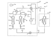
- FIG. 1 It is a schematic block diagram of the refrigerating-cycle apparatus 100 which concerns on embodiment. It is a refrigerant circuit figure of refrigerating cycle device 100 concerning an embodiment. It is the figure which showed the outdoor heat exchanger 5 typically. It is a block diagram of a control function of refrigerating cycle device 100 concerning an embodiment. It is operation
- refrigerant circuit figure of modification 1 of refrigerating cycle device 100 concerning an embodiment. It is a refrigerant circuit figure of modification 2 of refrigerating cycle device 100 concerning an embodiment. It is a figure showing typically outdoor heat exchanger 5t of modification 3 of refrigerating cycle device 100 concerning an embodiment.
- FIG. 1 is a schematic configuration diagram of a refrigeration cycle apparatus 100 according to the embodiment.
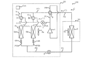
- FIG. 2 is a refrigerant circuit diagram of the refrigeration cycle apparatus 100 according to the embodiment.
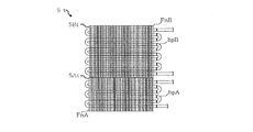
- FIG. 3 is a view schematically showing the outdoor heat exchanger 5.
- the refrigeration cycle apparatus 100 includes an outdoor unit 20 having an outdoor heat exchanger 5 and an indoor unit 30 connected to the outdoor unit 20 via a pipe P2 and a pipe P3.
- the refrigeration cycle apparatus 100 is an air conditioner.
- the refrigeration cycle apparatus 100 includes a heating operation in which the outdoor heat exchanger 5 functions as an evaporator, a cooling operation in which the outdoor heat exchanger 5 functions as a condenser, and a frost formed on the outdoor heat exchanger 5 during the heating operation. Defrosting operation, and can be performed.
- the outdoor unit 20 includes a compressor 1 for compressing a refrigerant, a decompression device 3 for decompressing a refrigerant, an outdoor heat exchanger 5 functioning as an evaporator during heating operation, and an outdoor unit for supplying air to the outdoor heat exchanger 5
- a fan 5 a and a flow path switching valve 9 provided on the discharge side of the compressor 1 are provided.
- the pressure reducing device 3 is provided downstream of the indoor heat exchanger 2 in the flow direction of the refrigerant during the heating operation, and is provided upstream of the outdoor heat exchanger 5 in the flow direction of the refrigerant during the heating operation. Moreover, as shown in FIG.
- the outdoor heat exchanger 5 has a lower heat exchanger 5A and an upper heat exchanger 5B provided on the lower heat exchanger 5A.
- the volume of the lower heat exchanger 5A and the volume of the upper heat exchanger 5B are the same.
- the lower heat exchanger 5A has a plate-like fin FnA and a heat transfer pipe hpA provided on the fin FnA and in which the refrigerant flows.
- the upper heat exchanger 5B has a plate-like fin FnB and a heat transfer pipe hpB provided on the fin FnB and in which the refrigerant flows.
- the outdoor unit 20 also includes a capillary tube 4A connected to the lower heat exchanger 5A and a capillary tube 4B connected to the upper heat exchanger 5B.
- the outdoor unit 20 also includes a switching unit 8 connected to the outdoor heat exchanger 5 and a valve 7 that opens and closes.
- the switching unit 8 has a first state connecting the discharge side of the compressor 1 and the lower heat exchanger 5A, a second state connecting the discharge side of the compressor 1 and the upper heat exchanger 5B, and outdoor heat. This is a valve that switches between the third state in which the exchanger 5 and the flow path switching valve 9 are connected.
- the outdoor unit 20 includes a control device Cnt that controls various actuators such as the compressor 1 and the like.
- the indoor unit 30 includes an indoor heat exchanger 2 that functions as a condenser during heating operation, and an indoor fan 2a that supplies air to the indoor heat exchanger 2.
- the refrigeration cycle apparatus 100 includes a refrigerant circuit C including a compressor 1, an indoor heat exchanger 2, a pressure reducing device 3, and an outdoor heat exchanger 5.
- the refrigerant circuit C includes a compressor 1, a flow path switching valve 9, an indoor heat exchanger 2, a pressure reducing device 3, a capillary tube 4A, a capillary tube 4B, an outdoor heat exchanger 5, a main circuit C1 having a switching unit 8, and a valve And a bypass circuit C2.
- the bypass circuit C2 bypasses the indoor heat exchanger 2 and the pressure reducing device 3 in the configuration of the main circuit C1.
- the main circuit C1 includes a pipe P1 connecting the discharge side of the compressor 1 and the flow path switching valve 9, a pipe P2 connecting the flow path switching valve 9 and the indoor heat exchanger 2, an indoor heat exchanger 2 and a pressure reducing device And a pipe P4 connected to the downstream side of the pressure reducing device 3 in the refrigerant flow direction during the heating operation.
- the main circuit C1 also includes a pipe P5A connecting the pipe P4 and the capillary tube 4A, a pipe P5B connecting the pipe P4 and the capillary tube 4B, and a pipe P6A connecting the lower heat exchanger 5A and the switching unit 8; It has piping P6B which connects the upper side heat exchanger 5B and the switching part 8. As shown in FIG.
- the main circuit C1 has a pipe P7 connecting the switching unit 8 and the flow path switching valve 9, and a pipe P8 connecting the flow path switching valve 9 and the suction side of the compressor 1.
- the bypass circuit C2 has a bypass pipe P9A connecting the pipe P1 and the valve 7 and a bypass pipe P9B connecting the valve 7 and the switching unit 8.
- the bypass pipe P9A and the bypass pipe P9B connect the discharge side of the compressor 1 and the switching unit 8.
- FIG. 4 is a block diagram of a control function of the refrigeration cycle apparatus 100 according to the embodiment.
- the control device Cnt includes an operation unit 50A that performs an operation, a control unit 50B that controls an actuator, and a storage unit 50C that stores data.
- the calculation unit 50A has a function of comparing the time elapsed since the start of various operations such as heating operation with a predetermined threshold.
- the control unit 50B controls the compressor 1, the pressure reducing device 3, the indoor blower 2a, the outdoor blower 5a, the valve 7, the switching unit 8, and the flow passage switching valve 9.
- the storage unit 50C stores data such as a threshold value used when shifting from the heating operation to the defrosting operation.
- Each functional unit included in the control device Cnt is configured by dedicated hardware or an MPU (Micro Processing Unit) that executes a program stored in a memory.
- the controller Cnt is a dedicated hardware
- the controller Cnt may be, for example, a single circuit, a composite circuit, an application specific integrated circuit (ASIC), a field-programmable gate array (FPGA), or a combination thereof.
- ASIC application specific integrated circuit
- FPGA field-programmable gate array
- Each of the functional units realized by the control device Cnt may be realized by individual hardware, or each functional unit may be realized by one hardware.
- each function executed by the control device is realized by software, firmware, or a combination of software and firmware. The software and firmware are described as a program and stored in the storage unit 50C.
- the MPU implements each function of the control device Cnt by reading and executing a program stored in the memory.
- the storage unit 50 is, for example, a non-volatile or volatile semiconductor memory such as a RAM, a ROM, a flash memory, an EPROM, and an EEPROM.
- FIG. 5 is an operation explanatory view of the heating operation of the refrigeration cycle apparatus 100 according to the embodiment.
- the switching state of the switching unit 8 is the third state. That is, the switching unit 8 connects the lower heat exchanger 5A and the flow path switching valve 9 and connects the upper heat exchanger 5B and the flow path switching valve 9. Further, in FIG. 5, the flow path switching valve 9 connects the discharge side of the compressor 1 to the indoor heat exchanger 2 and connects the switching portion 8 to the suction side of the compressor 1. Also, in FIG. 5, the valve 7 is closed. Furthermore, in FIG. 5, the indoor blower 2a and the outdoor blower 5a are in operation.
- the refrigerant discharged from the compressor 1 flows into the indoor heat exchanger 2 after passing through the flow path switching valve 9.
- the refrigerant flowing into the indoor heat exchanger 2 is liquefied.
- the refrigerant flowing out of the indoor heat exchanger 2 is decompressed by the decompression device 3.
- the refrigerant decompressed by the decompression device 3 is in a gas-liquid two-phase state.
- the refrigerant flowing out of the pressure reducing device 3 flows into the outdoor heat exchanger 5.
- the refrigerant flowing into the outdoor heat exchanger 5 is gasified.
- the refrigerant that has flowed out of the outdoor heat exchanger 5 returns to the compressor 1 after passing through the flow path switching valve 9.
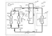
- FIG. 6 is an operation explanatory view of the cooling operation of the refrigeration cycle apparatus 100 according to the embodiment.
- the switching state of the switching unit 8 is the third state.
- the flow path switching valve 9 connects the discharge side of the compressor 1 and the switching unit 8 and connects the indoor heat exchanger 2 and the suction side of the compressor 1.
- the valve 7 is closed.
- the indoor blower 2a and the outdoor blower 5a are in operation. The flow of the refrigerant during the cooling operation is opposite to the flow of the refrigerant during the heating operation described with reference to FIG.
- the defrosting method for the defrosting operation of the refrigeration cycle apparatus 100 is a hot gas defrosting method in which the hot gas discharged from the compressor 1 is supplied to the outdoor heat exchanger 5.
- the defrosting operation of the refrigeration cycle apparatus 100 is executed after the first defrosting control for defrosting the lower heat exchanger 5A and the first defrosting control to defrost the upper heat exchanger 5B.
- a second defrosting control and a third defrosting control that is executed after the second defrosting control to defrost the lower heat exchanger 5A are provided.
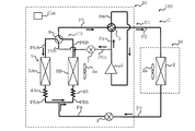
- FIG. 7 is an operation explanatory view of the first defrost control of the defrosting operation of the refrigeration cycle apparatus 100 according to the embodiment.
- the switching state of the switching unit 8 is in the first state. That is, the switching unit 8 connects the discharge side of the compressor 1 and the lower heat exchanger 5A, and connects the upper heat exchanger 5B and the flow path switching valve 9.
- the discharge side of the compressor 1 and the lower heat exchanger 5A are connected via the pipe P1, the bypass circuit C2, the switching unit 8, and the pipe P6A.
- the upper heat exchanger 5B and the flow path switching valve 9 are connected via the pipe P6B, the switching unit 8 and the pipe P7. Further, in FIG.
- the state of the flow path switching valve 9 is the same as the state of the flow path switching valve 9 in the heating operation described with reference to FIG. 5. Also, in FIG. 7, the valve 7 is open. Furthermore, in FIG. 7, the indoor blower 2a and the outdoor blower 5a are in operation.
- Part of the refrigerant discharged from the compressor 1 flows into the indoor heat exchanger 2 after passing through the flow path switching valve 9.
- the refrigerant flowing into the indoor heat exchanger 2 is liquefied. That is, even when the first defrosting control is performed, the indoor heat exchanger 2 functions as a condenser, so warm air is supplied to the room from the indoor unit 30.
- the refrigerant flowing out of the indoor heat exchanger 2 is decompressed by the decompression device 3.
- the refrigerant decompressed by the decompression device 3 is in a gas-liquid two-phase state.
- the other part of the refrigerant discharged from the compressor 1, that is, the hot gas flows into the lower heat exchanger 5A via the bypass circuit C2 and the switching unit 8.
- the heat of the hot gas flowing into the lower heat exchanger 5A is supplied to the frost of the lower heat exchanger 5A, and as a result, the frost of the lower heat exchanger 5A is melted.
- the refrigerant flowing out of the lower heat exchanger 5A merges with the refrigerant decompressed by the decompression device 3.
- the joined refrigerant flows into the upper heat exchanger 5B.
- the refrigerant flowing into the upper heat exchanger 5B is gasified. That is, in the first defrosting control, the upper heat exchanger 5B functions as an evaporator.
- the refrigerant flowing out of the upper heat exchanger 5B returns to the compressor 1 after passing through the flow path switching valve 9.
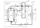
- FIG. 8 is an operation explanatory view of second defrosting control of the defrosting operation of the refrigeration cycle apparatus 100 according to the embodiment.
- the switching state of the switching unit 8 is in the second state. That is, the switching unit 8 connects the discharge side of the compressor 1 and the upper heat exchanger 5B, and connects the lower heat exchanger 5A and the flow path switching valve 9.
- the discharge side of the compressor 1 and the upper heat exchanger 5B are connected via the pipe P1, the bypass circuit C2, the switching unit 8, and the pipe P6B.
- the lower heat exchanger 5A and the flow path switching valve 9 are connected via the pipe P6A, the switching unit 8 and the pipe P7. Further, in FIG.
- the state of the flow path switching valve 9 is the same as the state of the flow path switching valve 9 in the heating operation described in FIG. 5. Also, in FIG. 8, the valve 7 is open. Furthermore, in FIG. 8, the indoor blower 2a and the outdoor blower 5a are in operation.
- the refrigerant flowing into the indoor heat exchanger 2 is liquefied. That is, even when the second defrosting control is performed as in the first defrosting control, the indoor heat exchanger 2 functions as a condenser, so warm air is supplied to the room from the indoor unit 30. .
- the refrigerant flowing out of the indoor heat exchanger 2 is decompressed by the decompression device 3.
- the refrigerant decompressed by the decompression device 3 is in a gas-liquid two-phase state.
- the other part of the refrigerant discharged from the compressor 1, that is, the hot gas flows into the upper heat exchanger 5B via the bypass circuit C2 and the switching unit 8.
- the heat of the hot gas flowing into the upper heat exchanger 5B is supplied to the frost of the upper heat exchanger 5B, and as a result, the frost of the upper heat exchanger 5B is melted.
- the refrigerant flowing out of the upper heat exchanger 5B merges with the refrigerant decompressed by the decompression device 3.
- the joined refrigerant flows into the lower heat exchanger 5A.
- the refrigerant flowing into the lower heat exchanger 5A is gasified. That is, in the second defrosting control, the lower heat exchanger 5A functions as an evaporator.
- the refrigerant flowing out of the lower heat exchanger 5A returns to the compressor 1 after passing through the flow path switching valve 9.
- FIG. 9 is an operation explanatory view of the third defrost control of the defrosting operation of the refrigeration cycle apparatus 100 according to the embodiment.
- the operation state of the third defrost control shown in FIG. 9 is the same as the operation state of the first defrost control shown in FIG. That is, in FIG. 9, the switching state of the switching unit 8 is in the first state. That is, the switching state of the switching unit 8 in the third defrosting control is the same as the switching state of the switching unit 8 in the first defrosting control.
- the state of the flow path switching valve 9 is the same as the state of the flow path switching valve 9 in the heating operation described with reference to FIG. 5. Also, in FIG. 9, the valve 7 is open. Furthermore, in FIG.
- the indoor blower 2a and the outdoor blower 5a are in operation.
- the flow of the refrigerant in the third defrosting control is the same as the flow of the refrigerant in the first defrosting control, and thus the description thereof will be omitted.
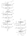
- FIG. 10 is a control flowchart of the refrigeration cycle apparatus 100 according to the embodiment.
- Control device Cnt starts the control flow concerning defrosting operation (Step S0).
- the control device Cnt acquires the time elapsed since the start of the heating operation, that is, the heating operation time ht (step S1).
- Arithmetic unit 50A of control device Cnt determines whether heating operation time ht is longer than predetermined time Th (step S2). If the heating operation time ht is longer than the predetermined time Th, the control device Cnt starts the defrosting operation (step S3).
- the control device Cnt executes the first defrosting control. That is, the control device Cnt switches the switching state of the switching unit 8 from the third state to the first state, and opens the valve 7. Further, the control device Cnt maintains the state of the flow path switching valve 9.
- the control device Cnt acquires the time elapsed since the start of the first defrosting control, that is, the execution time t1 of the first defrosting control (step S4).
- Arithmetic unit 50A of control device Cnt determines whether or not execution time t1 is longer than predetermined time T1 (step S5). If the execution time t1 is longer than the predetermined time T1, the control device Cnt ends the first defrost control and starts the second defrost control (step S6). That is, the control device Cnt switches the switching state of the switching unit 8 from the first state to the second state. Further, the control device Cnt keeps the valve 7 open and maintains the state of the flow path switching valve 9.
- the control device Cnt acquires the time elapsed since the start of the second defrosting control, that is, the execution time t2 of the second defrosting control (step S7).
- Arithmetic unit 50A of control device Cnt determines whether or not execution time t2 is longer than predetermined time T2 (step S8).
- time T1 is shorter than time T2. That is, the execution time of the first defrosting control is shorter than the execution time of the second defrosting control.
- the control device Cnt ends the second defrost control and starts the third defrost control (step S9). That is, the control device Cnt switches the switching state of the switching unit 8 from the second state to the first state. Further, the control device Cnt keeps the valve 7 open and maintains the state of the flow path switching valve 9.
- the control device Cnt acquires the time elapsed since the start of the third defrosting control, that is, the execution time t3 of the third defrosting control (step S10).
- Arithmetic unit 50A of control device Cnt determines whether or not execution time t3 is longer than predetermined time T3 (step S11).
- time T1 is shorter than time T3. That is, the execution time of the first defrosting control is shorter than the execution time of the third defrosting control. If the execution time t3 is longer than the predetermined time T3, the control device Cnt ends the third defrosting control (step S12). In step S12, the control device Cnt ends the defrosting operation and resumes the heating operation.
- control device Cnt switches the switching state of the switching unit 8 from the first state to the third state, and closes the valve 7. Further, the control device Cnt maintains the state of the flow path switching valve 9. The control device Cnt ends the control flow relating to the defrosting operation (step S13).
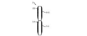
- FIG. 11 is a schematic view showing the state of the frost Fr1 formed in the lower heat exchanger 5A and the frost Fr2 formed in the upper heat exchanger 5B during the heating operation.
- the frost Fr1 is formed on the lower heat exchanger 5A
- the frost Fr2 is formed on the upper heat exchanger 5B.
- the volume of the lower heat exchanger 5A and the volume of the upper heat exchanger 5B are the same, it is assumed that the amount of the frost Fr1 and the amount of the frost Fr2 are the same.
- FIG. 12 is a schematic diagram showing how the frost Fr1a of the lower heat exchanger 5A melts when the first defrosting control is being performed.
- the frost Fr1 melts and the water dra flows downward.
- the frost Fr1 may be completely melted if the amount of the frost Fr1 is small, but in the description herein, it is assumed that the frost Fr1 remains to be melted. That is, by performing the first defrosting control, part of the frost Fr1 is melted.
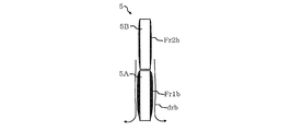
- FIG. 13 is a schematic diagram showing how the frost Fr2b of the upper heat exchanger 5B melts and how the water drb refreezes in the lower heat exchanger 5A when the second defrosting control is being performed. .
- the frost Fr2 shown in FIG. 12 melts and becomes a frost Fr2b.
- the frost Fr2 shown in FIG. 12 melts, the water drb flows from the upper heat exchanger 5B to the lower heat exchanger 5A.
- the drained water drb is cooled to the lower heat exchanger 5A functioning as an evaporator and the frost remaining in the lower heat exchanger 5A.
- FIG. 14 is a schematic view showing the state of the frost Fr1c remaining in the lower heat exchanger 5A when the second defrosting control is finished.
- the execution time of the second defrost control is longer than the execution time of the first defrost control. Therefore, the amount of frost that can be melted by executing the second defrosting control is larger than the amount of frost that can be melted by executing the first defrosting control.
- the frost Fr2b shown in FIG. 13 is completely melted.
- the water drb shown in FIG. 13 freezes on the surface of the lower heat exchanger 5A or freezes due to the frost formed on the lower heat exchanger 5A.
- the frost of the lower heat exchanger 5A becomes thick and the amount of frost not in contact with the lower heat exchanger 5A as a heat source Will increase.
- the first defrosting control is executed before the second defrosting control, thickening of the frost on the lower heat exchanger 5A at the start of the third defrosting operation is suppressed. ing.
- FIG. 15 is a schematic view showing the outdoor heat exchanger 5 when the third defrosting control is finished.
- the frost on the lower heat exchanger 5A at the start of the third defrosting operation is suppressed from being thickened. For this reason, the frost Fr1c shown in FIG. 14 is melted by executing the third defrosting control.
- the conventional refrigeration cycle apparatus performs defrosting of the upper heat exchanger and then performs defrosting of the lower heat exchanger. That is, the defrosting of the outdoor heat exchanger of the conventional refrigeration cycle apparatus is a two-stage defrosting including the defrosting of the upper heat exchanger and the defrosting of the lower heat exchanger.
- the defrosting operation of the conventional refrigeration cycle apparatus when defrosting of the upper heat exchanger is performed, the water that has fallen from the upper heat exchanger comes in contact with the frost of the lower heat exchanger and flows from the upper heat exchanger Water freezes in the frost on the lower heat exchanger.
- the thickness of the frost of the lower heat exchanger at the start of defrosting of the lower heat exchanger is thicker than the thickness of the frost of the lower heat exchanger at the start of defrosting of the upper heat exchanger. turn into.
- the frost in contact with the lower heat exchanger receives heat directly from the lower heat exchanger, the frost in contact with the lower heat exchanger is easily melted.
- the frost which is not in contact with the lower heat exchanger for example, the outer part of the frost of the lower heat exchanger receives the heat conducted via the frost or the like in contact with the lower heat exchanger. For this reason, the frost outside of the lower heat exchanger is less likely to melt.
- the control device Cnt of the refrigeration cycle apparatus 100 executes the first defrost control before executing the second defrost control.
- the increase in the thickness of the frost of lower side heat exchanger 5A at the time of the start of the third defrosting control is suppressed, and as a result, the defrosting efficiency of lower side heat exchanger 5A at the time of the third defrosting control
- the control device Cnt restarts the heating operation. Since the amount of frost remaining in the lower heat exchanger 5A at the end of the third defrosting control is suppressed, the heat transfer pipe of the lower heat exchanger 5A is performed when the restarted heating operation is being performed.
- the inhibition of heat exchange between the hpA refrigerant and the air passing through the lower heat exchanger 5A is suppressed. Therefore, when performing the heating operation resumed after the defrosting operation, the reduction of the heat exchange efficiency of the lower heat exchanger 5A is suppressed, and as a result, the reduction of the heating operation of the refrigeration cycle apparatus 100 Be suppressed.
- the time obtained by combining the execution time of the first defrost control and the execution time of the third defrost control is X
- the execution time of the second defrost control is Y
- the defrosting time of the lower heat exchanger of the conventional refrigeration cycle apparatus is X time
- the defrosting time of the upper heat exchanger of the conventional refrigeration cycle apparatus is Y time.
- the controller Cnt of the refrigeration cycle apparatus 100 executes the first defrost control before executing the second defrost control, the lower heat exchange at the start of the third defrost control It is because it is suppressed that the frost of container 5A becomes thick, as a result, the fall of the defrost efficiency of lower side heat exchanger 5A at the time of the 3rd defrost control is controlled.
- the execution time of the third defrosting control of the refrigeration cycle apparatus 100 is predetermined. However, as described above, since the thickening of the frost on the lower heat exchanger 5A at the start of the third defrosting control is suppressed, the administrator of the refrigeration cycle apparatus 100 determines that the lower heat exchanger It is not necessary to set the execution time of the third defrosting control longer than necessary due to the remaining unmelted frost of 5A. That is, the refrigeration cycle apparatus 100 is configured to easily set the defrosting operation time short. Here, if the defrosting operation time can be shortened, a delay in the timing of returning from the defrosting operation to the heating operation is also suppressed. Therefore, in the refrigeration cycle apparatus 100, the ratio of the heating operation time to the total operation time including the heating operation time and the defrosting operation time is suppressed to be small. Therefore, the refrigeration cycle apparatus 100 has the effect of suppressing the decrease in the indoor temperature.
- the indoor heat exchanger 2 When the refrigeration cycle apparatus 100 is performing a defrosting operation, the indoor heat exchanger 2 functions as a condenser. Specifically, when the control device Cnt is executing the first defrost control, the second defrost control, and the third defrost control, the indoor heat exchanger 2 functions as a condenser. . Therefore, the refrigeration cycle apparatus 100 can perform indoor heating by the indoor unit 30 while performing defrosting of the outdoor heat exchanger 5 by the outdoor unit 20.
- the execution time of the first defrosting control is the execution of the third defrosting control Even if the time is shorter than the time, it is assumed that the total time obtained by combining the execution time of the first defrost control and the execution time of the third defrost control is constant.
- the execution time of the third defrosting control is shorter than the execution time of the first defrosting control, the lower heat exchange in the first defrosting control is performed because the execution time of the first defrosting control is longer. The amount of frost melted in the vessel 5A increases.
- the amount of frost formation of lower side heat exchanger 5A will increase by execution of the 2nd defrost control. For this reason, in the case where the execution time of the third defrost control is shorter than the execution time of the first defrost control, the third defrost control execution time is shorter than the execution time of the third defrost control. At the end time, the frost of the lower heat exchanger 5A tends to be left undissolved. Therefore, in the refrigeration cycle apparatus 100, the execution time of the first defrosting control is shorter than the execution time of the third defrosting control. In other words, in the refrigeration cycle apparatus 100, the execution time of the third defrosting control is longer than the execution time of the first defrosting control.
- the refrigeration cycle apparatus 100 generates the frost on the lower heat exchanger 5A at the end of the third defrosting control. Has the effect of making it difficult to melt.
- the amount of water flowing from the upper heat exchanger 5B to the lower heat exchanger 5A increases during the second defrosting control as the frost formation amount of the upper heat exchanger 5B increases.
- the frost formation amount of the upper heat exchanger 5B becomes larger, the frost formation amount of the lower heat exchanger 5A at the start of the third defrosting control tends to increase. For this reason, when the frost formation amount of the upper heat exchanger 5B becomes large, the effect that the frost of the lower heat exchanger 5A becomes difficult to remain undissolved at the end of the third defrosting control becomes more remarkable.
- the execution time of the first defrosting control is set too long, the defrosting of the lower heat exchanger 5A will be performed even though the frost of the lower heat exchanger 5A is completely melted. That is, if the execution time of the first defrost control is set too long, the proportion of the time in which the frost is not melted, that is, the useless time increases among the execution times of the first defrost control. Therefore, in the refrigeration cycle apparatus 100, the execution time of the first defrosting control is shorter than the execution period of the second defrosting control. As described above, since the execution time of the first defrost control is suppressed, the refrigeration cycle apparatus 100 suppresses the increase in the ratio of the time during which the frost is not melted in the execution time of the first defrost control. Have an effect.
- the control device Cnt starts the defrosting operation when a predetermined time has elapsed since the heating operation was started. That is, the refrigeration cycle apparatus 100 does not require the temperature sensor used to determine whether to start the defrosting operation. For this reason, the manufacturing cost of the refrigeration cycle apparatus 100 is suppressed.
- the refrigeration cycle apparatus 100 includes a switching unit 8, a bypass pipe P9A, a bypass pipe P9B, and a valve 7. Then, the control device Cnt closes the valve 7 in the heating operation. Thus, in the heating operation, the hot gas is not supplied to the bypass circuit C2, and the hot gas is supplied to the indoor heat exchanger 2. As a result, the indoor heat exchanger 2 functions as a condenser, and the outdoor heat exchanger 5 functions as an evaporator. Further, the control device Cnt sets the switching state of the switching unit 8 in the first state or the second state and opens the valve 7 in the defrosting operation. Thus, in the defrosting operation, the hot gas is supplied to the bypass circuit C2 and the indoor heat exchanger 2.
- the indoor heat exchanger 2 functions as a condenser, and one of the lower heat exchanger 5A and the upper heat exchanger 5B is defrosted, and the lower heat exchanger 5A and the upper heat exchanger 5B are defrosted.
- the other functions as an evaporator.
- FIG. 16 is a refrigerant circuit diagram of Modification Example 1 of the refrigeration cycle apparatus 100 according to the embodiment.
- the switching unit 8 is configured to be able to switch between the first state, the second state, and the third state.
- the switching unit 8t of the first modification includes a three-way valve 8a and a three-way valve 8b.
- the switching unit 8 t also has the same function as the switching unit 8.
- the bypass pipe P9Bt of the first modification is connected to the three-way valve 8a and the three-way valve 8b.
- the pipe P6At of the first modification connects the three-way valve 8a to the lower heat exchanger 5A, and the pipe P6Bt of the first modification connects the three-way valve 8b to the upper heat exchanger 5B.
- the three-way valve 8 a switches between a state A connecting the discharge side of the compressor 1 and the lower heat exchanger 5 A, and a state B connecting the lower heat exchanger 5 A and the flow path switching valve 9.
- the three-way valve 8 b switches between a state C connecting the discharge side of the compressor 1 and the upper heat exchanger 5 B and a state D connecting the upper heat exchanger 5 B and the flow path switching valve 9.
- the control device Cnt sets the three-way valve 8 a to the state B and sets the three-way valve 8 b to the state D.
- the control device Cnt sets the three-way valve 8 a to the state A and sets the three-way valve 8 b to the state D. Furthermore, in the second defrosting control, the control device Cnt sets the three-way valve 8 a to the state B and sets the three-way valve 8 b to the state C.
- This modification 1 also has the same effect as the refrigeration cycle apparatus 100 according to the embodiment.
- FIG. 17 is a refrigerant circuit diagram of Modification 2 of the refrigeration cycle apparatus 100 according to the embodiment.
- the refrigeration cycle apparatus 100 according to the embodiment is configured to be able to switch between the heating operation and the cooling operation.
- the modification 2 does not have the flow path switching valve 9. For this reason, although the modification 2 can perform heating operation, it can not perform cooling operation.
- This modification 2 also has the same effect as the refrigeration cycle apparatus 100 according to the embodiment.
- FIG. 18 is a view schematically showing an outdoor heat exchanger 5t of Modification 3 of the refrigeration cycle apparatus 100 according to the embodiment.
- the volume of the lower heat exchanger 5A and the volume of the upper heat exchanger 5B are the same.
- the volume of the lower heat exchanger 5At is smaller than the volume of the upper heat exchanger 5Bt.
- the combined volume of the volume of the lower heat exchanger 5At and the volume of the upper heat exchanger 5Bt is the same as the volume of the volume of the lower heat exchanger 5A and the volume of the upper heat exchanger 5B. .
- the frost formation amount of the lower heat exchanger 5At at the start of the defrosting operation is the upper side at the start of the defrosting operation. It is smaller than the amount of frost formation of the heat exchanger 5Bt.
- the amount of heat supplied per unit time to the lower heat exchanger 5A in the first defrost control and the third defrost control is unit time to the lower heat exchanger 5A in the second defrost control. It is assumed that it is equivalent to the amount of heat supplied per unit.
- the amount of heat received by the unit heat of the lower heat exchanger 5At per unit time from the lower heat exchanger 5At is the upper heat exchange during the second defrosting control.
- the unit mass frost of the container 5Bt becomes larger than the amount of heat received from the upper heat exchanger 5Bt per unit time. That is, the defrosting efficiency of the third defrosting control is improved as compared to the defrosting efficiency of the second defrosting control. Since the amount of frost formation is increased by the second defrosting control in the lower heat exchanger 5At, the demand for improvement of the defrosting efficiency of the third defrosting control is high.
- the defrosting efficiency of the third defrosting control of the third modification is improved as described above, the amount of frost remaining in the lower heat exchanger 5A is suppressed at the end of the third defrosting control. Ru. Further, during the first defrosting control, the amount of heat received by the unit heat of the lower heat exchanger 5At per unit time from the heat of the lower heat exchanger 5At during the second defrosting control is the upper heat exchanger 5Bt. The unit mass frost is larger than the amount of heat received from the upper heat exchanger 5Bt per unit time. That is, the defrosting efficiency of the first defrosting control is also improved as compared with the defrosting efficiency of the second defrosting control.
- the amount of frost formation on the lower heat exchanger 5A is suppressed.
- the amount of frost remaining in the lower heat exchanger 5A is further suppressed.
Landscapes
- Engineering & Computer Science (AREA)
- Physics & Mathematics (AREA)
- Mechanical Engineering (AREA)
- Thermal Sciences (AREA)
- General Engineering & Computer Science (AREA)
- Air Conditioning Control Device (AREA)
Abstract
Selon la présente invention, lorsqu'un dispositif de commande exécute des fonctionnements de dégivrage destinés à faire fondre le givre sur un échangeur de chaleur extérieur, le dispositif de commande exécute une première commande de dégivrage destinée à définir un état de commutation d'une partie de commutation en tant que premier état, puis, après avoir exécuté la première commande de dégivrage, exécute une deuxième commande de dégivrage destinée à définir l'état de commutation de la partie de commutation en tant que second état, et ensuite, après avoir exécuté la deuxième commande de dégivrage, effectue une troisième commande de dégivrage destinée à définir à nouveau l'état de commutation de la partie de commutation en tant que premier état.
Priority Applications (6)
| Application Number | Priority Date | Filing Date | Title |
|---|---|---|---|
| CN201880086512.0A CN111630330B (zh) | 2018-01-26 | 2018-01-26 | 空气调节装置 |
| PCT/JP2018/002475 WO2019146071A1 (fr) | 2018-01-26 | 2018-01-26 | Dispositif à cycle frigorifique |
| JP2019567492A JP6899927B2 (ja) | 2018-01-26 | 2018-01-26 | 空気調和装置 |
| US16/961,005 US11927381B2 (en) | 2018-01-26 | 2018-01-26 | Air-conditioning apparatus |
| EP18902790.7A EP3745053A4 (fr) | 2018-01-26 | 2018-01-26 | Dispositif à cycle frigorifique |
| RU2020127718A RU2742855C1 (ru) | 2018-01-26 | 2018-01-26 | Устройство кондиционирования воздуха |
Applications Claiming Priority (1)
| Application Number | Priority Date | Filing Date | Title |
|---|---|---|---|
| PCT/JP2018/002475 WO2019146071A1 (fr) | 2018-01-26 | 2018-01-26 | Dispositif à cycle frigorifique |
Publications (1)
| Publication Number | Publication Date |
|---|---|
| WO2019146071A1 true WO2019146071A1 (fr) | 2019-08-01 |
Family
ID=67394897
Family Applications (1)
| Application Number | Title | Priority Date | Filing Date |
|---|---|---|---|
| PCT/JP2018/002475 Ceased WO2019146071A1 (fr) | 2018-01-26 | 2018-01-26 | Dispositif à cycle frigorifique |
Country Status (6)
| Country | Link |
|---|---|
| US (1) | US11927381B2 (fr) |
| EP (1) | EP3745053A4 (fr) |
| JP (1) | JP6899927B2 (fr) |
| CN (1) | CN111630330B (fr) |
| RU (1) | RU2742855C1 (fr) |
| WO (1) | WO2019146071A1 (fr) |
Families Citing this family (2)
| Publication number | Priority date | Publication date | Assignee | Title |
|---|---|---|---|---|
| CN112984897B (zh) * | 2021-02-08 | 2022-10-25 | 青岛海尔生物医疗股份有限公司 | 一种冷藏箱及用于该冷藏箱的湿度控制方法 |
| CN116294272A (zh) * | 2023-03-07 | 2023-06-23 | 浙江中广电器集团股份有限公司 | 一种热泵空调系统及其除霜控制方法 |
Citations (4)
| Publication number | Priority date | Publication date | Assignee | Title |
|---|---|---|---|---|
| JPH0914816A (ja) * | 1995-06-23 | 1997-01-17 | Sharp Corp | 保冷装置用蒸発器の除霜装置 |
| JPH1089817A (ja) * | 1996-08-31 | 1998-04-10 | Lg Electron Inc | ヒートポンプの積霜防止装置 |
| JP4272224B2 (ja) | 2006-09-07 | 2009-06-03 | 日立アプライアンス株式会社 | 空気調和機 |
| JP2009133578A (ja) * | 2007-11-30 | 2009-06-18 | Daikin Ind Ltd | 冷凍装置 |
Family Cites Families (15)
| Publication number | Priority date | Publication date | Assignee | Title |
|---|---|---|---|---|
| US4313313A (en) * | 1980-01-17 | 1982-02-02 | Carrier Corporation | Apparatus and method for defrosting a heat exchanger of a refrigeration circuit |
| GB2167543B (en) * | 1984-11-26 | 1988-09-21 | Sanden Corp | Refrigerated display cabinet |
| KR0129641Y1 (ko) * | 1995-03-30 | 1999-01-15 | 김광호 | 공기조화기의 실내기 |
| US5771699A (en) * | 1996-10-02 | 1998-06-30 | Ponder; Henderson F. | Three coil electric heat pump |
| US6244057B1 (en) * | 1998-09-08 | 2001-06-12 | Hitachi, Ltd. | Air conditioner |
| KR20100081621A (ko) * | 2009-01-06 | 2010-07-15 | 엘지전자 주식회사 | 공기조화기 및 공기조화기의 제상운전방법 |
| JP2012013363A (ja) * | 2010-07-02 | 2012-01-19 | Panasonic Corp | 空気調和機 |
| AU2012271757B2 (en) * | 2011-06-13 | 2016-03-24 | Fred LINGELBACH | Condenser evaporator system (CES) for a refrigeration system and method |
| CN103797308B (zh) * | 2011-09-13 | 2016-10-05 | 三菱电机株式会社 | 制冷空调装置 |
| SE537022C2 (sv) * | 2012-12-21 | 2014-12-09 | Fläkt Woods AB | Förfarande och anordning för avfrostning av en förångare vidett luftbehandlingsaggregat |
| JP6688555B2 (ja) * | 2013-11-25 | 2020-04-28 | 三星電子株式会社Samsung Electronics Co.,Ltd. | 空気調和機 |
| US10018388B2 (en) * | 2014-02-27 | 2018-07-10 | Mitsubishi Electric Corporation | Heat source side unit and refrigeration cycle apparatus |
| JP6201872B2 (ja) * | 2014-04-16 | 2017-09-27 | 三菱電機株式会社 | 空気調和機 |
| WO2016166801A1 (fr) * | 2015-04-13 | 2016-10-20 | 三菱電機株式会社 | Dispositif de climatisation |
| JP6642247B2 (ja) * | 2016-04-28 | 2020-02-05 | 株式会社デンソー | 冷凍サイクル装置 |
-
2018
- 2018-01-26 EP EP18902790.7A patent/EP3745053A4/fr active Pending
- 2018-01-26 WO PCT/JP2018/002475 patent/WO2019146071A1/fr not_active Ceased
- 2018-01-26 US US16/961,005 patent/US11927381B2/en active Active
- 2018-01-26 CN CN201880086512.0A patent/CN111630330B/zh active Active
- 2018-01-26 RU RU2020127718A patent/RU2742855C1/ru active
- 2018-01-26 JP JP2019567492A patent/JP6899927B2/ja active Active
Patent Citations (4)
| Publication number | Priority date | Publication date | Assignee | Title |
|---|---|---|---|---|
| JPH0914816A (ja) * | 1995-06-23 | 1997-01-17 | Sharp Corp | 保冷装置用蒸発器の除霜装置 |
| JPH1089817A (ja) * | 1996-08-31 | 1998-04-10 | Lg Electron Inc | ヒートポンプの積霜防止装置 |
| JP4272224B2 (ja) | 2006-09-07 | 2009-06-03 | 日立アプライアンス株式会社 | 空気調和機 |
| JP2009133578A (ja) * | 2007-11-30 | 2009-06-18 | Daikin Ind Ltd | 冷凍装置 |
Non-Patent Citations (1)
| Title |
|---|
| See also references of EP3745053A4 |
Also Published As
| Publication number | Publication date |
|---|---|
| CN111630330B (zh) | 2022-04-15 |
| US20210080160A1 (en) | 2021-03-18 |
| CN111630330A (zh) | 2020-09-04 |
| JP6899927B2 (ja) | 2021-07-07 |
| RU2742855C1 (ru) | 2021-02-11 |
| EP3745053A4 (fr) | 2021-01-13 |
| EP3745053A1 (fr) | 2020-12-02 |
| US11927381B2 (en) | 2024-03-12 |
| JPWO2019146071A1 (ja) | 2020-11-19 |
Similar Documents
| Publication | Publication Date | Title |
|---|---|---|
| JP5634682B2 (ja) | 空気調和機 | |
| JP6402661B2 (ja) | 冷凍装置 | |
| JP6320567B2 (ja) | 空気調和装置 | |
| JP6768546B2 (ja) | 空気調和機 | |
| JP6138711B2 (ja) | 空気調和装置 | |
| JP6266456B2 (ja) | 空気調和機 | |
| US11029067B2 (en) | Refrigeration apparatus with defrost during heating operation | |
| JP5210364B2 (ja) | 空気調和機 | |
| JP6524670B2 (ja) | 空気調和装置 | |
| CN113498468A (zh) | 制冷循环装置 | |
| JP6749507B1 (ja) | 空気調和機 | |
| WO2019224944A1 (fr) | Climatiseur | |
| JP6899927B2 (ja) | 空気調和装置 | |
| JP2013200085A (ja) | 空気調和機 | |
| JP2009145032A (ja) | 冷凍サイクル装置およびそれを備えた空気調和機 | |
| WO2018189830A1 (fr) | Dispositif à cycle de réfrigération | |
| JP2019138599A (ja) | 空気調和装置 | |
| JP7093236B2 (ja) | 空気調和機及び制御方法 | |
| JP2017009260A (ja) | 空気調和装置 | |
| CN104251596B (zh) | 用于直冷冰箱的化霜系统控制方法 | |
| JPWO2019008744A1 (ja) | 冷凍サイクル装置 | |
| JP2007232274A (ja) | 空気調和装置 | |
| JP2012127542A (ja) | 空気調和装置 | |
| JP2002061994A (ja) | 空気調和機 | |
| JP2013120030A (ja) | 空気調和機 |
Legal Events
| Date | Code | Title | Description |
|---|---|---|---|
| 121 | Ep: the epo has been informed by wipo that ep was designated in this application |
Ref document number: 18902790 Country of ref document: EP Kind code of ref document: A1 |
|
| ENP | Entry into the national phase |
Ref document number: 2019567492 Country of ref document: JP Kind code of ref document: A |
|
| NENP | Non-entry into the national phase |
Ref country code: DE |
|
| ENP | Entry into the national phase |
Ref document number: 2018902790 Country of ref document: EP Effective date: 20200826 |