WO2019146206A1 - Machine de travail, procédé de commande de machine de travail, programme, et support d'enregistrement pour celui-ci - Google Patents
Machine de travail, procédé de commande de machine de travail, programme, et support d'enregistrement pour celui-ci Download PDFInfo
- Publication number
- WO2019146206A1 WO2019146206A1 PCT/JP2018/040859 JP2018040859W WO2019146206A1 WO 2019146206 A1 WO2019146206 A1 WO 2019146206A1 JP 2018040859 W JP2018040859 W JP 2018040859W WO 2019146206 A1 WO2019146206 A1 WO 2019146206A1
- Authority
- WO
- WIPO (PCT)
- Prior art keywords
- boom
- arm
- cylinder
- rotation axis
- range
- Prior art date
- Legal status (The legal status is an assumption and is not a legal conclusion. Google has not performed a legal analysis and makes no representation as to the accuracy of the status listed.)
- Ceased
Links
Images




Classifications
-
- E—FIXED CONSTRUCTIONS
- E02—HYDRAULIC ENGINEERING; FOUNDATIONS; SOIL SHIFTING
- E02F—DREDGING; SOIL-SHIFTING
- E02F3/00—Dredgers; Soil-shifting machines
- E02F3/04—Dredgers; Soil-shifting machines mechanically-driven
- E02F3/28—Dredgers; Soil-shifting machines mechanically-driven with digging tools mounted on a dipper- or bucket-arm, i.e. there is either one arm or a pair of arms, e.g. dippers, buckets
- E02F3/36—Component parts
- E02F3/42—Drives for dippers, buckets, dipper-arms or bucket-arms
- E02F3/43—Control of dipper or bucket position; Control of sequence of drive operations
- E02F3/435—Control of dipper or bucket position; Control of sequence of drive operations for dipper-arms, backhoes or the like
- E02F3/437—Control of dipper or bucket position; Control of sequence of drive operations for dipper-arms, backhoes or the like providing automatic sequences of movements, e.g. linear excavation, keeping dipper angle constant
-
- E—FIXED CONSTRUCTIONS
- E02—HYDRAULIC ENGINEERING; FOUNDATIONS; SOIL SHIFTING
- E02F—DREDGING; SOIL-SHIFTING
- E02F3/00—Dredgers; Soil-shifting machines
- E02F3/04—Dredgers; Soil-shifting machines mechanically-driven
- E02F3/28—Dredgers; Soil-shifting machines mechanically-driven with digging tools mounted on a dipper- or bucket-arm, i.e. there is either one arm or a pair of arms, e.g. dippers, buckets
- E02F3/36—Component parts
- E02F3/42—Drives for dippers, buckets, dipper-arms or bucket-arms
- E02F3/43—Control of dipper or bucket position; Control of sequence of drive operations
- E02F3/435—Control of dipper or bucket position; Control of sequence of drive operations for dipper-arms, backhoes or the like
-
- E—FIXED CONSTRUCTIONS
- E02—HYDRAULIC ENGINEERING; FOUNDATIONS; SOIL SHIFTING
- E02F—DREDGING; SOIL-SHIFTING
- E02F3/00—Dredgers; Soil-shifting machines
- E02F3/04—Dredgers; Soil-shifting machines mechanically-driven
- E02F3/28—Dredgers; Soil-shifting machines mechanically-driven with digging tools mounted on a dipper- or bucket-arm, i.e. there is either one arm or a pair of arms, e.g. dippers, buckets
- E02F3/30—Dredgers; Soil-shifting machines mechanically-driven with digging tools mounted on a dipper- or bucket-arm, i.e. there is either one arm or a pair of arms, e.g. dippers, buckets with a dipper-arm pivoted on a cantilever beam, i.e. boom
- E02F3/301—Dredgers; Soil-shifting machines mechanically-driven with digging tools mounted on a dipper- or bucket-arm, i.e. there is either one arm or a pair of arms, e.g. dippers, buckets with a dipper-arm pivoted on a cantilever beam, i.e. boom with more than two arms (boom included), e.g. two-part boom with additional dipper-arm
-
- E—FIXED CONSTRUCTIONS
- E02—HYDRAULIC ENGINEERING; FOUNDATIONS; SOIL SHIFTING
- E02F—DREDGING; SOIL-SHIFTING
- E02F3/00—Dredgers; Soil-shifting machines
- E02F3/04—Dredgers; Soil-shifting machines mechanically-driven
- E02F3/28—Dredgers; Soil-shifting machines mechanically-driven with digging tools mounted on a dipper- or bucket-arm, i.e. there is either one arm or a pair of arms, e.g. dippers, buckets
- E02F3/30—Dredgers; Soil-shifting machines mechanically-driven with digging tools mounted on a dipper- or bucket-arm, i.e. there is either one arm or a pair of arms, e.g. dippers, buckets with a dipper-arm pivoted on a cantilever beam, i.e. boom
- E02F3/32—Dredgers; Soil-shifting machines mechanically-driven with digging tools mounted on a dipper- or bucket-arm, i.e. there is either one arm or a pair of arms, e.g. dippers, buckets with a dipper-arm pivoted on a cantilever beam, i.e. boom working downwardly and towards the machine, e.g. with backhoes
- E02F3/325—Backhoes of the miniature type
-
- E—FIXED CONSTRUCTIONS
- E02—HYDRAULIC ENGINEERING; FOUNDATIONS; SOIL SHIFTING
- E02F—DREDGING; SOIL-SHIFTING
- E02F3/00—Dredgers; Soil-shifting machines
- E02F3/04—Dredgers; Soil-shifting machines mechanically-driven
- E02F3/28—Dredgers; Soil-shifting machines mechanically-driven with digging tools mounted on a dipper- or bucket-arm, i.e. there is either one arm or a pair of arms, e.g. dippers, buckets
- E02F3/34—Dredgers; Soil-shifting machines mechanically-driven with digging tools mounted on a dipper- or bucket-arm, i.e. there is either one arm or a pair of arms, e.g. dippers, buckets with bucket-arms, i.e. a pair of arms, e.g. manufacturing processes, form, geometry, material of bucket-arms directly pivoted on the frames of tractors or self-propelled machines
- E02F3/3414—Dredgers; Soil-shifting machines mechanically-driven with digging tools mounted on a dipper- or bucket-arm, i.e. there is either one arm or a pair of arms, e.g. dippers, buckets with bucket-arms, i.e. a pair of arms, e.g. manufacturing processes, form, geometry, material of bucket-arms directly pivoted on the frames of tractors or self-propelled machines the arms being pivoted at the rear of the vehicle chassis, e.g. skid steer loader
-
- E—FIXED CONSTRUCTIONS
- E02—HYDRAULIC ENGINEERING; FOUNDATIONS; SOIL SHIFTING
- E02F—DREDGING; SOIL-SHIFTING
- E02F3/00—Dredgers; Soil-shifting machines
- E02F3/04—Dredgers; Soil-shifting machines mechanically-driven
- E02F3/28—Dredgers; Soil-shifting machines mechanically-driven with digging tools mounted on a dipper- or bucket-arm, i.e. there is either one arm or a pair of arms, e.g. dippers, buckets
- E02F3/36—Component parts
- E02F3/42—Drives for dippers, buckets, dipper-arms or bucket-arms
- E02F3/43—Control of dipper or bucket position; Control of sequence of drive operations
- E02F3/431—Control of dipper or bucket position; Control of sequence of drive operations for bucket-arms, front-end loaders, dumpers or the like
-
- E—FIXED CONSTRUCTIONS
- E02—HYDRAULIC ENGINEERING; FOUNDATIONS; SOIL SHIFTING
- E02F—DREDGING; SOIL-SHIFTING
- E02F3/00—Dredgers; Soil-shifting machines
- E02F3/04—Dredgers; Soil-shifting machines mechanically-driven
- E02F3/96—Dredgers; Soil-shifting machines mechanically-driven with arrangements for alternate or simultaneous use of different digging elements
- E02F3/963—Arrangements on backhoes for alternate use of different tools
- E02F3/964—Arrangements on backhoes for alternate use of different tools of several tools mounted on one machine
-
- E—FIXED CONSTRUCTIONS
- E02—HYDRAULIC ENGINEERING; FOUNDATIONS; SOIL SHIFTING
- E02F—DREDGING; SOIL-SHIFTING
- E02F9/00—Component parts of dredgers or soil-shifting machines, not restricted to one of the kinds covered by groups E02F3/00 - E02F7/00
- E02F9/20—Drives; Control devices
- E02F9/2025—Particular purposes of control systems not otherwise provided for
- E02F9/2033—Limiting the movement of frames or implements, e.g. to avoid collision between implements and the cabin
Definitions
- the present invention relates to, for example, a work machine such as a backhoe.
- Patent Document 1 is a backhoe comprising a machine body, a boom mounted on the machine body, an arm pivotally supported by the boom, and a bucket provided at the tip of the arm.
- the boom, the arm, and the bucket can be rocked by the expansion and contraction of the boom cylinder, the arm cylinder, and the bucket cylinder, respectively.
- the strokeable range of the arm cylinder is a position where the boom cylinder is most separated from the lower surface of the boom to the arm side so that the bucket and the boom cylinder do not collide.
- the reference position is set so that the bucket and the boom cylinder do not collide at this reference position.
- the strokeable range of the arm cylinder is made constant within the range set at the above-mentioned reference position, the distance between the boom cylinder and the bucket is the boom cylinder at the reference position when the boom is turned away from the reference position. And spread more than the distance between the bucket. For this reason, depending on the attitude of the boom, the arm and the bucket can not be sufficiently brought close to the boom side, and there is a problem that the minimum turning radius may be increased.
- an object of this invention is to provide the working machine which can fully move an arm and a working tool to the boom side irrespective of the attitude
- a work machine includes a machine body, a boom whose proximal end is pivotally supported by the machine body about a first rotation axis, and turns the boom about the first rotation axis.
- a boom cylinder a base end of which is pivotally supported on a distal end of the boom about a second rotation axis parallel to the first rotation axis, and the arm about the second rotation axis
- the boom cylinder includes an arm cylinder to be pivoted, and a work tool pivotably supported at a tip end of the arm about a third rotation axis parallel to the first rotation axis, and the boom cylinder is one surface of the boom It is a working machine disposed on the side and the arm cylinder is disposed on the other surface side of the boom, provided on the first rotary shaft and the base end side of the boom and capable of pivoting the boom cylinder A first straight line connecting the fourth rotation axis to be pivoted; When the pivot position of the boom at which the second straight line parallel to the extending direction of the da
- the controller is provided with a control device that is set according to the pivot position of the boom such that the shortest path distance, which is the shortest distance of the above, is maintained at a predetermined value.
- the arm and the work tool can be sufficiently brought close to the boom regardless of the attitude of the boom.
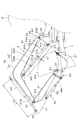
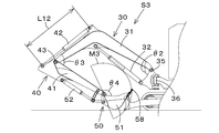
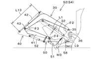
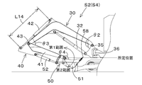
- FIG. 1 It is a side view of a working machine. It is the schematic of the hydraulic system of a working machine. It is a side view of the working machine when the boom is at the boom reference position S1. It is a side view of the working machine in a state where the boom is rotated upward from the boom reference position S1 while keeping the stroke of the arm cylinder constant. The boom is pivoted upward from the boom reference position S1 while changing the strokeable range of the arm cylinder according to the pivot position of the boom so as to keep the distance between the pivot path of the work tool and the boom cylinder constant at the reference distance. It is a side view of the working machine in the state where it was made to move. FIG.
- FIG. 6 is a side view of the working machine in a state in which the boom is rotated in a direction approaching the boom reference position while keeping the stroke of the arm cylinder constant from the state of FIG. 5.
- FIG. 7 is a side view of a working machine showing a method of setting the strokeable range of the arm cylinder such that the distance between the tip of the bucket and the boom cylinder is equal to or greater than a reference distance.
- a method of determining whether the turning position of the bucket is a first range in which the tip end is disposed closer to the boom cylinder than a predetermined position or a second range disposed on the side (dump side) far from the boom cylinder It is a side view of the working machine shown.
- FIG. 1 is a schematic side view of the work machine 1 according to the present embodiment.
- a backhoe which is a turning work machine is illustrated as the work machine 1.
- the working machine 1 includes a machine body (pivot table) 2, a traveling device 3, and a working device 4.
- a cabin 5 is mounted on the fuselage 2.
- a driver's seat (seat) 6 on which a driver (operator) is seated is provided in the cabin of the cabin 5.
- the front side of the driver sitting in the driver's seat 6 of the work machine 1 (direction of arrow A1 in FIG. 1) is forward, and the rear side of the driver (direction of arrow A2 in FIG.
- the left side is described as the left, and the driver's right side is described as the right.
- the horizontal direction which is a direction orthogonal to the front-rear direction K1 will be described as the machine width direction (the width direction of the machine 2).
- the traveling device 3 is a device that supports the machine body 2 so that the vehicle 2 can travel.
- the traveling device 3 is driven by a traveling motor 11 configured by a hydraulic motor (hydraulic actuator), an electric motor, or the like.
- a traveling motor 11 configured by a hydraulic motor (hydraulic actuator), an electric motor, or the like.
- the crawler type traveling device 3 is used in the present embodiment, the present invention is not limited to this, and a wheel type traveling device or the like may be used.
- a dozer device 7 is mounted at the front of the traveling device 3.
- the dozer device 7 can raise and lower (raise and lower) the blade (discharge plate) 74 by expanding and contracting a dozer cylinder (hydraulic actuator) (not shown).
- the airframe 2 is pivotably supported on the traveling device 3 via a pivot bearing 8 about a pivot axis X1.
- the pivot axis X ⁇ b> 1 is an axis extending in the vertical direction passing through the center of the pivot bearing 8.
- the aircraft 2 is equipped with a motor.
- the prime mover is a diesel engine.
- the prime mover may be a gasoline engine, an LPG engine or an electric motor, or may be a hybrid type having an engine and an electric motor.
- the airframe 2 has a pivoting base 9 which pivots around a pivot axis X1.
- the revolving base 9 is formed of a steel plate or the like, and constitutes the bottom of the machine body 2.
- the prime mover is mounted on the swing base 9.
- a weight 10 is provided at the rear of the fuselage 2.
- a support 20 for supporting the working device 4 is provided at the front of the airframe 2.
- the support 20 has a support bracket 20A and a swing bracket 20B.
- the support bracket 20A is fixed to the front of the longitudinal ribs 9L and 9R, and is provided so as to project forward from the machine body 2.
- a swing bracket 20B is attached to a front portion of the support bracket 20A (a part protruding from the machine body 2) so as to be pivotable about a longitudinal axis via a swing shaft 21. Accordingly, the swing bracket 20B is rotatable in the machine body width direction K2 (horizontally around the swing shaft 21).
- the swing bracket 20 ⁇ / b> B is formed with a cylindrical first pivot support 23 provided at the upper part of the main body 22 and a tubular second pivot support 24 provided at the lower part of the main body 22.
- the work device 4 includes a boom device 30, an arm device 40, and a work implement device 50.
- the boom device 30 has a boom 31 and a boom cylinder 32.
- the boom 31 is a base 31A supported swingably (rotatably) via a horizontal axis (first rotation axis) 35 extending in the machine body width direction K2 of the first pivoting portion 23 of the swing bracket 20B, and an arm It has a tip end portion 31B for pivotally supporting the arm 41, and an intermediate portion 31C provided between the base portion 31A and the tip end portion 31B.
- the middle portion 31C is elongated along the longitudinal direction, and is bent downward at the middle portion.
- the lower bracket 33 is provided on one side (lower side) of the bending portion in the middle portion 31C
- the upper bracket 34 is provided on the other side (upper side) of the bending portion in the middle portion 31C.
- the boom cylinder 32 is an expandable hydraulic cylinder that swings (rotates) the boom 31.
- the boom cylinder 32 has a cylindrical cylinder portion 32A and a rod 32B, one end of which is slidably inserted in the cylinder portion 32A.
- a guard member may be provided on the surface of the boom cylinder 32 on the side of the arm 41 (lower side) to prevent the rod 32B and / or the cylinder portion 32A from contacting another object.
- the base end of the boom cylinder 32 is swingably supported by the horizontal axis (the fourth rotation axis) 36 of the second pivot portion 24, and the tip end of the boom cylinder 32 swings to the horizontal axis 37 of the lower bracket 33. It is freely supported. Therefore, the boom device 30 (boom 31) can be pivoted about the horizontal shaft 35 at the first pivot portion 23, and the boom device 30 (boom 31) can be pivoted upward or downward.
- the arm device 40 has an arm 41 and an arm cylinder 42.
- the arm 41 is elongated along the longitudinal direction.
- the base end of the arm 41 is swingably supported by the distal end 31 B of the boom 31 via a horizontal axis (second rotation axis) 43.
- an upper bracket 44 is provided on the upper surface side of the proximal end portion of the arm 41.
- the arm cylinder 42 is an expandable hydraulic cylinder that swings the arm 41.
- the proximal end of the arm cylinder 42 is pivotally supported by the lateral shaft 38 of the upper bracket 34 of the boom 31, and the distal end of the arm cylinder 42 is pivotally supported by the lateral shaft 46 of the upper bracket 44.
- the arm device 40 (arm 41) is pivotable about the horizontal axis 43 with respect to the boom 31, and the arm device 40 (arm 41) is pivotable upward or downward.
- the work implement device 50 includes a bucket 51 as a work implement and a bucket cylinder 52 as a work implement cylinder.
- the bucket 51 is swingably supported by the tip of the arm 41 via a horizontal axis (third rotation axis) 57.
- a link mechanism 53 is provided between the bucket 51 and the tip of the arm 41.
- the bucket cylinder 52 is configured of an expandable hydraulic cylinder that swings the bucket 51.
- the base end of the bucket cylinder 52 is swingably supported by the horizontal shaft 48 of the upper bracket 44 of the arm 41, and the tip of the bucket cylinder 52 is swingably supported by the horizontal shaft 56 of the link mechanism 53. There is.
- the work implement device 50 (bucket 51) is provided on the tip end side of the arm 41 so as to be able to perform the squeeze operation and the dumping operation.
- the squeeze operation is an operation of swinging the tip end portion 58 of the bucket 51 in the direction (direction of the squee) approaching the boom 31 and is, for example, an operation in the case of covering sand and the like.
- the dumping operation is an operation of swinging the tip end portion 58 of the bucket 51 in a direction to move away from the boom 31 (the direction of dumping), and is, for example, an operation in the case of dropping (discharging) earth and sand.
- the work machine 1 can mount other work (hydraulic attachment) that can be driven by a hydraulic actuator, instead of or in addition to the bucket 51.
- a hydraulic breaker, a hydraulic crusher, an angle bloom, an earth auger, a pallet fork, a sweeper, a mower, a snow blower, etc. can be exemplified.
- FIG. 2 is a diagram showing a hydraulic system of the work machine 1 for operating the work device 4.
- the hydraulic system of the work machine 1 includes a boom control valve 71, an arm control valve 72, a bucket control valve 73, a control device 60, steering devices 19L and 19R, and a boom angle sensor 91. , An arm angle sensor 92, and a work tool angle sensor 93.
- the boom control valve 71, the arm control valve 72, and the bucket control valve 73 are connected to the boom cylinder 32, the arm cylinder 42, and the bucket cylinder 52 via oil passages, respectively.
- a hydraulic pump P1 that discharges hydraulic oil is connected to the boom control valve 71, the arm control valve 72, and the bucket control valve 73 via oil passages, respectively.
- the boom control valve 71, the arm control valve 72, and the bucket control valve 73 are, for example, an electromagnetic three-position switching valve. Specifically, the boom control valve 71 can be switched to the first position 71A, the second position 71B, and the third position 71C by exciting or demagnetizing the first solenoid 71D and the second solenoid 71E.
- the boom control valve 71 is switched to the first position 71A, the boom cylinder 32 is extended by the supply and discharge of hydraulic fluid to the boom cylinder 32, and the boom 31 swings in the upward direction.
- the boom control valve 71 is switched to the second position 71B, the boom cylinder 32 contracts due to supply and discharge of hydraulic fluid to the boom cylinder 32, and the boom 31 swings in the downward direction.
- the arm control valve 72 can be switched to the first position 72A, the second position 72B, and the third position 72C by exciting or demagnetizing the first solenoid 72D and the second solenoid 72E.
- the arm control valve 72 switches to the first position 72A, supply and discharge of hydraulic fluid to the arm cylinder 42 extends the arm cylinder 42, and the arm 41 swings the arm 41 rearward and downward.
- the arm control valve 72 is switched to the second position 72B, supply and discharge of hydraulic fluid to the arm cylinder 42 causes the arm cylinder 42 to contract and swing forward and upward.
- the bucket control valve 73 can be switched to the first position 73A, the second position 73B, and the third position 73C by exciting or demagnetizing the first solenoid 73D and the second solenoid 73E.
- the bucket control valve 73 When the bucket control valve 73 is switched to the first position 73A, the bucket cylinder 52 extends by the supply and discharge of the hydraulic oil to the bucket cylinder 52, and the bucket 51 swings in the direction of the squeeze.
- the bucket control valve 73 switches to the second position 73B, the bucket cylinder 52 contracts due to the supply and discharge of the hydraulic fluid to the bucket cylinder 52, and the bucket 51 swings in the direction of dumping.
- the control device 60 includes a boom control unit 61, an arm control unit 62, and a bucket control unit 63, and controls switching operations of the boom control valve 71, the arm control valve 72, and the bucket control valve 73. That is, the control device 60 controls the operation of the boom 31, the arm 41 and the bucket 51.
- the control device 60 may be realized by a logic circuit (hardware) formed in an integrated circuit (IC chip) or the like, or may be realized by software using a computer.
- the computer is a program that is software that implements each function of the control device 60 and a recording medium on which various data related to the work machine 1 are recorded so as to be readable by the computer; It includes an arithmetic circuit such as a Central Processing Unit, and a RAM (Random Access Memory) for expanding the program and various data. Then, the arithmetic circuit reads the program from the recording medium and executes it, whereby the function of the control device 60 is realized.
- an arithmetic circuit such as a Central Processing Unit, and a RAM (Random Access Memory) for expanding the program and various data. Then, the arithmetic circuit reads the program from the recording medium and executes it, whereby the function of the control device 60 is realized.
- the control devices 60 are connected to control devices 19L and 19R which are held by the operator at the time of operation.
- the control devices 19L and 19R are provided near the driver's seat 6, respectively.
- the control devices 19L, 19R each have an operation lever 15 and a position sensor 16.
- the control lever 15 is pivotable from the neutral position to the front, back, right and left, and the position sensor 16 is a pivoting amount (operation amount) from the front, back, right and left neutral position of the control lever 15 To detect
- the control device 60 switches the boom control valve 71 by exciting or demagnetizing the first solenoid 71D and the second solenoid 71E in accordance with the swing direction and swing amount of the control lever 15.
- the control device 60 switches the arm control valve 72 by exciting or demagnetizing the first solenoid 72D and the second solenoid 72E in accordance with the swing direction and swing amount of the control lever 15.
- the control device 60 switches the bucket control valve 73 by exciting or demagnetizing the first solenoid 73D and the second solenoid 73E in accordance with the swing direction and swing amount of the control lever 15.
- control device 60 includes a boom angle sensor 91 for detecting a swing angle ⁇ 2 (rotational position) of the boom 31, and an arm angle sensor 92 for detecting a swing angle ⁇ 3 (rotational position) of the arm 41.
- a work tool angle sensor 93 is provided to detect a swing angle ⁇ 4 (rotational position) of the bucket 51 around the horizontal axis 57 with respect to the tip of the arm 41.
- a potentiometer is used as the boom angle sensor 91, the arm angle sensor 92, and the work tool angle sensor 93, but not limited to this, another angle sensor may be used, or the boom cylinder 32,
- the stroke (extension position) of the arm cylinder 42 and the bucket cylinder 52 may be detected, and the swing angle of the boom 31, the arm 41, and the bucket 51 may be calculated from the detection result.
- the control device 60 (arm control unit 62) has a boom device in which the distance between the boom device 30 and the tip portion 58 of the bucket 51 is The extension range of the arm cylinder 42 (the possible stroke range to move the arm 41 closer to the boom cylinder 32) to a reference distance (predetermined value) L1 for avoiding interference between the tip 30 and the tip portion 58 of the bucket 51 Set
- the value of the reference distance L1 may be a fixed value set by default, or may be arbitrarily changed.
- the boom reference position S1 is the pivoting track M3 of the tip portion 58 of the bucket 51 about the horizontal axis 57 and the boom when the boom 31 is rotated about the horizontal axis 35 while keeping the stroke of the arm cylinder 42 constant. This is the pivoting position of the boom 31 at which the shortest track distance, which is the shortest distance from the cylinder 32, becomes the minimum value.
- the boom reference position S1 is a boom position (boom angle) at which the distance between the boom cylinder 32 and the lower surface 31D of the boom 31 is the longest.
- the center of the horizontal shaft 35 of the first pivoting portion 23 that pivotally supports the base end of the boom 31 and the base end of the boom cylinder 32
- An angle ⁇ 1 formed with a certain second straight line M2 is substantially perpendicular.
- control device sets the extendable range of the arm cylinder 42 such that the shortest path distance at the boom reference position S1 becomes the reference distance L1. That is, in the state where boom 31 is boom reference position S1, control device (arm control unit 62) 60 is the boom device 30 (the most among the pivoting trajectories M3 of tip 58 when swinging bucket 51).
- the stroke possible range of the arm cylinder 42 is set such that the shortest path distance which is the distance between the proximity point P10 close to the boom cylinder 32) and the boom device 30 (boom cylinder 32) becomes the reference distance L1.
- the reference distance L1 is set to 80 mm, but the present invention is not limited to this value.
- the reference distance L1 may be set to be as short as possible within a range where the boom cylinder 32 and the bucket 51 can be appropriately prevented from contacting with each other.
- the reference distance L1 is preferably set within a range of 50 mm to 120 mm. It is more preferable to set in the range of 60 mm or more and 100 mm or less.
- the arm cylinder 42 has a margin which can be further extended in the direction to make the shortest path distance shorter than the reference distance L1 at the boom reference position S1, but the control device (Arm control unit 62) 60 limits the strokeable range (extensible range) of the arm cylinder 42.
- FIG. 4 shows a related art in which the boom 31 is swung upward while keeping the stroke of the arm cylinder 42 constant from the state in which the arm cylinder 42 is extended so that the shortest path distance becomes the reference distance L1 at the boom reference position S1.
- the boom swinging position S2 is shown when the control of (1) is performed. In this state, the shortest path distance L2 between the pivoting path M3 of the tip portion 58 of the bucket 51 and the boom cylinder 32 is larger than the reference distance L1.
- the arm control unit 62 (control device 60) rotates the boom 31 in a direction away from the arm reference position S1
- the strokeable range of the arm cylinder 42 (arm 41 According to the rotation position of the boom 31)
- the shortest distance between the rotation track M3 of the tip portion 58 of the bucket 51 and the boom cylinder 32 is the reference distance Set to keep L1.
- the boom control unit 61 operates the boom 31 in accordance with the operation of the operator.
- the arm control unit 62 is an arm cylinder for setting the rotation position of the boom 31 and the shortest path distance stored in advance as the reference distance L1 as the detection result of the rotation position of the boom 31 by the boom angle sensor 91.
- the strokeable range of the arm cylinder 42 is set based on the relationship with the strokeable range of 42.
- the arm control unit 62 refers to the swing angle ⁇ 2 (turning position) of the boom 31 input from the boom angle sensor 91 and the turning operation direction of the boom 31 by the operator, and makes the boom 31 the boom It is determined whether the operation is in the direction of moving away from the reference position S1. Then, when the arm control unit 62 determines that the operation of moving the boom 31 away from the boom reference position S1 is performed, the stroke of the arm cylinder 42 for setting the pivot position of the boom 31 and the shortest path distance to the reference distance L1. With reference to a table or function indicating the relationship with the possible range, the possible stroke range of the arm cylinder 42 is set based on the reference result.
- the shortest path distance matches the reference distance L1.
- the extension of the arm cylinder 42 is allowed to the position where That is, assuming that the maximum length of the arm cylinder 42 when performing the conventional control shown in FIG. 4 is L10, and the maximum length of the arm cylinder 42 when performing the control of this embodiment shown in FIG. L11> L10.
- the arm 41 and the bucket 51 can be sufficiently moved toward the boom 31 regardless of the attitude of the boom 31, and the length Lb of the working device 4 in the front-rear direction
- the possible stroke range can be made shorter than the length La (see FIG. 4) when keeping the same constant value as the boom reference position S1.
- the arm control part 62 (control apparatus 60) makes the boom 31 the boom reference position. The same control is performed when it is rotated downward from S1.
- control device 60 allows a stroke available range of arm cylinder 42 (allowing stroke of arm cylinder 42 to move arm 41 closer to boom 31) Range is set according to the pivot position of the boom 31 so that the shortest path distance between the pivot track M3 of the tip portion 58 of the bucket 51 and the boom cylinder 32 is maintained at the reference distance L1. .
- the tip end portion 58 of the bucket 51 can be brought close to or in contact with the blade 74 of the doser device 7. Therefore, the work (so-called dust removal work) of scooping soil and the like with the bucket 51 and the blade 74 of the dozer device 7 can be easily performed.
- the boom cylinder 32 turns the turning trajectory of the tip portion 58 of the bucket 51.
- the arm control unit 62 rotates the boom 31 in the direction approaching the boom reference position S1, and the boom 31 is not operated.
- the arm cylinder 42 is operated to move the tip of the bucket 51 when the shortest path distance, which is the shortest distance between the boom cylinder 32 and the pivoting track M3 of the tip 58 of the bucket 51, is less than the reference distance L1.
- the arm 41 is retracted in the direction in which the portion 58 moves away from the boom cylinder 32.
- the boom control unit 61 operates the boom 31 in accordance with the operation of the operator.
- the arm control unit 62 refers to the swing angle ⁇ 2 (rotational position) of the boom 31 input from the boom angle sensor 91 and the rotational operation direction of the boom 31 by the operator, and sets the boom 31 to the boom reference position S1. It is determined whether or not the operation is in the direction of approaching to.
- the arm control unit 62 determines that the operation is in a direction to bring the boom 31 closer to the boom reference position S1, the detection result of the pivot position of the boom 31 by the boom angle sensor 91 and the detection result of the arm 41 by the arm angle sensor 92. Based on the detection result of the rotational position, it is determined whether the shortest path distance is less than the reference distance L1 if only the boom 31 is operated without operating the arm cylinder 42. When it is determined that the distance is less than the reference distance L1, the arm control unit 62 operates (contracts) the arm cylinder 42 until the shortest path distance becomes the reference distance L1, and the tip 58 of the bucket 51 moves away from the boom cylinder 32 The arm 41 is retracted in the direction.
- the arm control unit 62 refers to a table or a function indicating the relationship between the pivoting position of the boom 31 and the pivoting position of the arm 41, and the stroke amount of the arm cylinder 42 for setting the shortest path distance to the reference distance L1.
- the (contraction amount) is specified, and the arm cylinder 42 is operated according to the specified stroke amount. Thereby, interference with boom cylinder 32 and bucket 51 can be prevented.
- the arm control unit 62 when the arm control unit 62 extends the arm cylinder 42 beyond the strokeable range set at the boom reference position S1, the arm control unit 62 electronically limits the operating speed of the arm cylinder 42 more than when extending the stroke within the strokeable range. Perform cushion control. Specifically, when the arm control unit 62 extends the arm cylinder 42 beyond the strokeable range set at the boom reference position S1 with the boom 31 rotated in the direction away from the boom reference position S1, the arm control unit 62 The pilot pressure supplied to the pressure receiving portion (pilot pressure receiving portion) of the control valve 72 is reduced. Thus, the operating speed of the arm cylinder 42 at the end of the strokeable range can be easily restricted regardless of the setting of the strokeable range of the arm cylinder 42.
- the arm control unit 62 detects the swing angle ⁇ 2 (rotational position) of the boom 31 by the boom angle sensor 91, and the detection result of the swing angle ⁇ 3 (rotational position) of the arm 41 by the arm angle sensor 92; And the tip distance which is the distance between the tip portion 58 of the bucket 51 and the boom cylinder 32 in the current swing position, based on the detection result of the swing angle .theta.4 (rotational position) of the bucket 51 by the work implement angle sensor 93. calculate. Then, as shown in FIG.
- the arm control unit 62 sets the calculated tip distance to the reference distance L1 as the strokeable range of the arm cylinder 42 (strokeable range toward the arm 31 closer to the boom 31). Set to stroke enable.
- the arm 41 and the bucket 51 can be further moved closer to the boom 31 than in the first embodiment.
- the boom control unit 61 operates the boom 31 according to the operation of the operator. Furthermore, the arm control unit 62 stores in advance the detection results of the rotational positions of the boom 31, the arm 41, and the bucket 51 by the boom angle sensor 91, the arm angle sensor 92, and the work implement angle sensor 93.
- the stroke of the arm cylinder 42 is possible based on a table or a function showing the relationship with the stroke available range of the arm cylinder 42 for making the tip distance which is the distance between the tip portion 58 of 51 and the boom cylinder 32 the reference distance L1. Set the range.
- the arm 41 and the bucket 51 can be closer to the boom 31 than in the first embodiment. it can. (2-3.
- the arm control unit 62 rotates the boom 31 in the direction approaching the boom reference position S 1, and when only the boom 31 is operated without operating the arm cylinder 42, the boom cylinder 32 and the tip end portion 58 of the bucket 51
- the arm cylinder 42 is operated to retract the arm 41 in the direction in which the tip portion 58 of the bucket 51 moves away from the boom cylinder 32 when the tip distance, which is the distance between the two, is less than the reference distance L1.
- the boom control unit 61 operates the boom 31 according to the operation of the operator.
- the arm control unit 62 also detects the rotational position of the boom 31 by the boom angle sensor 91, the detection result of the rotational position of the arm 41 by the arm angle sensor 92, and the rotation of the bucket 51 by the work tool angle sensor 93. Based on the detection result of the movement position, it is determined whether the tip distance becomes less than the reference distance L1 if the boom 31 is operated without operating the arm cylinder 42 and the bucket 51.
- the arm control unit 62 When it is determined that the distance is less than the reference distance L1, the arm control unit 62 operates (contracts) the arm cylinder 42 until the tip distance becomes the reference distance L1, and the tip portion 58 of the bucket 51 moves away from the boom cylinder 32
- the arm 41 is retracted. That is, the arm control unit 62 refers to a table or function indicating the relationship between the pivot position of the boom 31, the pivot position of the arm 41, and the pivot position of the bucket 51 and the stroke of the arm cylinder 42 and the tip distance.
- the stroke amount (contraction amount) of the arm cylinder 42 for setting the tip distance to the reference distance L1 is specified, and the arm cylinder 42 is operated according to the specified stroke amount. Thereby, interference with boom cylinder 32 and bucket 51 can be prevented.
- the arm control unit 62 rotates the bucket 51 in a direction approaching the boom cylinder 32.
- the tip distance becomes less than the reference distance L1.
- the arm cylinder 42 is operated to retract the arm 41 in the direction in which the tip end portion 58 of the bucket 51 moves away from the boom cylinder 32.
- the bucket control unit 63 operates the bucket 51 in accordance with the operator's operation.
- the arm control unit 62 also detects the rotational position of the boom 31 by the boom angle sensor 91, the detection result of the rotational position of the arm 41 by the arm angle sensor 92, and the rotation of the bucket 51 by the work tool angle sensor 93. Based on the detection result of the movement position, it is determined whether the tip distance becomes less than the reference distance L1 when the bucket 51 is operated without operating the arm cylinder 42.
- the arm control unit 62 When it is determined that the distance is less than the reference distance L1, the arm control unit 62 operates (contracts) the arm cylinder 42 until the tip distance becomes the reference distance L1, and the tip portion 58 of the bucket 51 moves away from the boom cylinder 32
- the arm 41 is retracted. That is, the arm control unit 62 refers to a table or function indicating the relationship between the pivot position of the boom 31, the pivot position of the arm 41, and the pivot position of the bucket 51 and the stroke of the arm cylinder 42 and the tip distance.
- the stroke amount (contraction amount) of the arm cylinder 42 for setting the tip distance to the reference distance L1 is specified, and the arm cylinder 42 is operated according to the specified stroke amount. Thereby, interference with boom cylinder 32 and bucket 51 can be prevented.
- the arm control unit 62 operates the arm cylinder 42 as needed to operate the arm cylinder 42 in the same manner, and the tip end portion 58 of the bucket 51 is operated. Retracts the arm 41 in a direction away from the boom cylinder 32.
- the arm control unit 62 arranges the current turning position of the bucket 51 at the predetermined position of the bucket 51.
- No. 5 (see FIG. 8), or the tip 58 is a first range disposed on the boom cylinder 32 side (cloud side), or a tip disposed distal to the boom cylinder 32 side (dump side) Determine if it is 2 range.
- the predetermined position described above is not particularly limited.
- the predetermined position may be set to the rotational position of the bucket 51 when the control device 19R is in the neutral position, and the tip 58 of the bucket 51 is the axis of the arm 41 (A straight line passing through the center of the horizontal axis 43 and the center of the horizontal axis 57) may be disposed, or may be set at the central position of the pivotable range of the tip 58 of the bucket 51.
- the stroke possible range of the arm cylinder 42 corresponds to the first embodiment described above. It sets according to the rotation position of the boom 31 by the same method. Further, when the arm control unit 62 determines that the current rotational position of the bucket 51 is in the second range (the dump side of the predetermined position), the stroke possible range of the arm cylinder 42 is the trajectory at the boom reference position S1. The shortest distance is set to be constant within the possible stroke range where the second predetermined value is shorter than the reference distance L1. As a result, as shown in FIG.
- the maximum length L14 of the arm cylinder 42 is set to the boom swing position S2 (see FIG. 5) in the first embodiment.
- the arm 41 and the bucket 51 can be further moved closer to the boom 31 side than in the first embodiment by setting the length longer than the set maximum length L11 of the arm cylinder 42.
- the bucket 51 can be prevented from coming into contact with the boom cylinder 32, and the arm 41 and the bucket 51 can be sufficiently brought close to the boom 31 regardless of the attitude of the boom 31.
- the bucket control unit 63 performs the cloud operation of the bucket 51 (from the state where the current rotational position of the bucket 51 is in the second range (the dump side of the predetermined position) to the second range (the tip portion 58 of the bucket 51 to the boom cylinder 32 side)
- the rotation range of the bucket 51 is set to a predetermined position, and the operation of the bucket 51 is stopped when the rotation position of the bucket 51 reaches the predetermined position.
- the tip end portion 58 of the bucket 51 can be reliably prevented from coming into contact with the boom cylinder 32.
- the strokeable range of the arm cylinder 42 is set to the rotation position of the boom 31 Regardless of this, the shortest possible distance of the trajectory at the boom reference position S1 may be set to be constant within the possible stroke range where the reference distance L1 is reached.
- Embodiment 4 Another embodiment of the present invention will be described.
- symbol is attached
- the strokeable range of the arm cylinder 42 is set according to the pivoting position of the boom 31 based on the pivoting position of the boom 31 and the pivoting position of the bucket 51 or the pivoting of the boom 31 The configuration has been described which switches whether the position is constant or not.
- the strokeable range of the arm cylinder 42 is set according to the pivoting position of the bucket 51 regardless of the pivoting position of the boom 31.
- the arm control unit 62 determines whether the current turning position of the bucket 51 is in the first range, Determine if it is 2 range.
- the setting method of the first range and the second range is the same as that of the third embodiment.
- the strokeable range of the arm cylinder 42 is set to the rotational position of the boom 31 Regardless of the setting, a fixed range in which the shortest path distance at the boom reference position S1 is the reference distance (predetermined value) L1 is set.
- the stroke possible range of the arm cylinder 42 is the trajectory at the boom reference position S1. It is set in a fixed range in which the shortest distance is a second predetermined value shorter than the reference distance L1.
- the maximum length L14 of the arm cylinder 42 is set to the boom swing position S2 (see FIG. 5) in the first embodiment.
- the arm 41 and the bucket 51 can be further moved closer to the boom 31 side than in the first embodiment by setting the length longer than the set maximum length L11 of the arm cylinder 42.
- the bucket 51 can be prevented from coming into contact with the boom cylinder 32, and the arm 41 and the bucket 51 can be sufficiently brought close to the boom 31 regardless of the attitude of the boom 31.
- the bucket control unit 63 performs the cloud operation of the bucket 51 (from the state where the current rotational position of the bucket 51 is in the second range (the dump side of the predetermined position) to the second range (the tip portion 58 of the bucket 51 to the boom cylinder 32 side)
- the rotation range of the bucket 51 is set to a predetermined position, and the operation of the bucket 51 is stopped when the rotation position of the bucket 51 reaches the predetermined position.
- the tip end portion 58 of the bucket 51 can be reliably prevented from coming into contact with the boom cylinder 32.
- the work machine 1 includes the machine body, the boom whose proximal end is pivotally supported by the machine body about the first rotation axis, and the boom.
- a boom cylinder which is pivoted about a rotational axis, an arm whose proximal end is pivotally supported by a distal end of the boom about a second rotational axis parallel to the first rotational axis, and the arm
- the boom cylinder includes: an arm cylinder pivoted about a second rotation axis; and a work tool pivotally supported at a tip end of the arm about a third rotation axis parallel to the first rotation axis, the boom cylinder Is a working machine disposed on one side of the boom, and the arm cylinder is disposed on the other side of the boom, provided on the first rotary shaft and the base end of the boom, and the boom And a first straight line connecting a fourth rotation shaft pivotally supporting the cylinder Assuming that a pivot position of the boom at which
- the strokeable range of the arm cylinder is set according to the pivot position of the boom so that the shortest path distance is maintained at a predetermined value even if the pivot position of the boom changes.
- the arm and the work tool can be sufficiently brought close to the boom regardless of the attitude of the boom.
- the control device may set the strokeable range of the arm cylinder to be longer as the boom is pivoted away from the boom reference position.
- the control apparatus further includes a boom sensor that detects a pivoting position of the boom about the first rotation axis, and an arm sensor that detects a pivoting position of the arm about the second rotation axis.
- the arm cylinder may be operated to rotate the arm to a position where the shortest path distance is equal to or more than the predetermined value.
- the work tool can be appropriately prevented from contacting the boom cylinder.
- the turning position of the work tool about the third rotation axis is a first range in which the tip of the working unit is disposed closer to the boom cylinder than the predetermined position, or is disposed farther from the boom cylinder
- a work tool sensor for detecting whether the arm cylinder is in the second range, and the control device is configured to move the arm cylinder to a strokeable range in which the arm approaches the boom; If it is in the first range, it is set according to the pivot position of the boom so that the shortest path distance becomes the predetermined value even if the pivot position of the boom changes, and the pivot position of the work tool
- the second range even if the pivoting position of the boom changes, setting according to the pivoting position of the boom so that the shortest path distance becomes a second predetermined value shorter than the predetermined value You may
- a working machine including: a machine body; a boom whose proximal end is pivotally supported by the machine body about a first rotation axis; and the boom around the first rotation axis
- a boom cylinder for pivoting, an arm whose proximal end is pivotally supported by a distal end of the boom about a second rotation axis parallel to the first rotation axis, and the arm rotates the second rotation
- An arm cylinder which is pivoted about an axis, a work tool pivotally supported by a tip end of the arm about a third rotation axis parallel to the first rotation axis, and the third rotation of the work tool It is detected whether the pivoting position about the axis is a first range where the tip of the working unit is disposed closer to the boom cylinder or a second range disposed farther from the boom cylinder than a predetermined position
- the boom cylinder with one side of the boom And the arm cylinder is disposed on the other side of the boom, the arm cylinder being
- the pivot position of the boom at which the first straight line connecting the supporting fourth rotation axis and the second straight line parallel to the extension direction of the boom cylinder are at right angles is the boom reference position, and the tip of the work tool
- the shortest possible distance between the pivoting track about the third rotation axis of the part and the boom cylinder is the shortest path distance, the strokeable range of the arm cylinder to the side bringing the arm closer to the boom
- the working tool can be appropriately prevented from contacting the boom cylinder, and the arm and the working tool can be sufficiently brought close to the boom regardless of the attitude of the boom.
- the control device rotates the work tool in a direction approaching the first range from a state in which the shortest path distance is smaller than the predetermined value and the work tool is in the second range.
- the strokeable range of the work implement cylinder may be limited to a range in which the tip end of the work implement does not enter the first range side.
- a working machine including: a machine body; a boom whose proximal end is pivotally supported by the machine body about a first rotation axis; and the boom as the first rotation axis
- a boom cylinder which is pivoted around, an arm whose proximal end is pivotally supported on a distal end of the boom about a second rotation axis parallel to the first rotation axis, and the second arm
- An arm cylinder that rotates about a rotation axis, a work tool pivotally supported by a tip end of the arm about a third rotation axis parallel to the first rotation axis, and the third of the work tools
- a work tool comprising: a work tool sensor for detecting a rotational position about a rotation axis; the boom cylinder disposed on one side of the boom; and the arm cylinder disposed on the other side of the boom.
- the boom reference position where the first straight line connecting the fourth rotation shaft pivotably supporting the boom cylinder and the second straight line parallel to the extension direction of the boom cylinder are perpendicular to each other.
- the pivotable position of the boom changes the strokeable range of the arm cylinder to the side for bringing the arm closer to the boom.
- the control device which is set according to the turning position of the boom and the turning position of the work such that the tip distance which is the shortest distance between the tip of the work and the boom cylinder is maintained at a predetermined value Is equipped.
- the strokeable range of the arm cylinder is set to the pivoting position of the boom and the pivoting position of the work such that the shortest path distance is maintained at a predetermined value even if the pivoting position of the boom changes.
- the control device rotates the work tool while keeping the stroke of the arm cylinder constant, in the case where the work tool is rotated in the direction in which the tip end portion of the work tool approaches the boom cylinder.
- the arm cylinder may be operated to pivot the arm to a position where the tip distance is equal to or more than the predetermined value when the tip distance is less than the predetermined value.
- the work tool can be appropriately prevented from contacting the boom cylinder.
- the control device may rotate the boom in a direction to approach the boom reference position, and the tip distance may be changed by rotating the boom while keeping the rotating position of the work tool constant.
- the arm cylinder may be operated to turn the arm to a position where the tip distance becomes equal to or more than the predetermined value.
- the work tool can be appropriately prevented from contacting the boom cylinder.
- the control device may limit the operating speed of the arm cylinder when the arm cylinder is stroked beyond the strokeable range at the boom reference position. According to the above configuration, by lowering the operation speed of the arm cylinder in the vicinity of the end of the arm cylinder in the strokeable range, it is possible to prevent the occurrence of vibration or impact due to abrupt stop of the operation of the arm.
- the first rotary shaft is connected to a fourth rotary shaft provided on the base end side of the boom and pivotally supporting the boom cylinder.
- the arm is pivoted in a direction away from the boom reference position.
- the strokeable range of the arm cylinder toward the side closer to the boom is the shortest distance between the boom cylinder and the pivoting track around the third rotation axis of the tip of the work even if the pivot position of the boom changes
- the shortest path distance is set in accordance with the pivot position of the boom so as to be maintained at a predetermined value.
- the first rotary shaft is connected to a fourth rotary shaft provided on the base end side of the boom and pivotally supporting the boom cylinder.
- the pivot position of the boom at which the straight line and the second straight line connecting both ends in the longitudinal direction of the boom cylinder are at a right angle is taken as the boom reference position.
- the strokeable range of the arm cylinder to the side bringing the arm closer to the boom is the first range regardless of the pivot position of the boom and the pivot position of the work tool is the first range
- the shortest track distance is set to a fixed range where the predetermined value is at the boom reference position, and when the rotational position of the work tool is the second range, the second shortest track distance is shorter than the predetermined value at the boom reference position Fixed range which becomes a predetermined value It is set.
- the first rotary shaft and a fourth rotary shaft provided on the base end side of the boom and pivotally supporting the boom cylinder are connected.
- the boom reference position the pivot position of the boom at which the first straight line and the second straight line parallel to the extending direction of the boom cylinder are perpendicular.
- the boom is pivoted away from the boom reference position.
- the tip distance which is the shortest distance between the tip of the work and the boom cylinder is maintained at a predetermined value even if the pivot position of the boom changes As described above, it is set according to the pivoting position of the boom and the pivoting position of the work tool.
- the control device provided in each work machine described above may be realized by a computer.
- a program that causes the computer to realize the control device by making the computer operate as each part of the control device, and Recorded computer readable recording media are also included in the scope of the present invention.
Landscapes
- Engineering & Computer Science (AREA)
- Mechanical Engineering (AREA)
- Mining & Mineral Resources (AREA)
- Civil Engineering (AREA)
- General Engineering & Computer Science (AREA)
- Structural Engineering (AREA)
- Life Sciences & Earth Sciences (AREA)
- General Life Sciences & Earth Sciences (AREA)
- Paleontology (AREA)
- Operation Control Of Excavators (AREA)
- Component Parts Of Construction Machinery (AREA)
Abstract
L'invention vise à amener un bras (41) et un outil de travail à être rapprochés suffisamment près d'une flèche (31) indépendamment de l'orientation de la flèche (31). A cet effet, l'invention porte sur une machine de travail (1), laquelle machine comprend un dispositif de commande (60) qui établit une plage de course pour un cylindre de bras (42) vers le côté où le bras (41) s'approche de la flèche (31) quand la flèche (31) est tournée dans une direction s'éloignant d'une position de référence de flèche (S1) en fonction de la position de rotation de la flèche (31), de telle sorte que la distance de trajectoire la plus courte (L2), qui est la distance la plus courte entre une trajectoire de rotation (M3) de l'extrémité distale d'un godet (51) et un cylindre de flèche (32), est maintenue à une valeur prescrite même si la position de rotation de la flèche (31) change.
Priority Applications (3)
| Application Number | Priority Date | Filing Date | Title |
|---|---|---|---|
| EP18902200.7A EP3744903B1 (fr) | 2018-01-23 | 2018-11-02 | Machine de travail, procédé de commande de machine de travail, programme, et support d'enregistrement pour celui-ci |
| CN201880081916.0A CN111542665B (zh) | 2018-01-23 | 2018-11-02 | 作业机、作业机的控制方法、程序及其记录介质 |
| US16/896,716 US12024850B2 (en) | 2018-01-23 | 2020-06-09 | Working machine and control method of working machine |
Applications Claiming Priority (2)
| Application Number | Priority Date | Filing Date | Title |
|---|---|---|---|
| JP2018-009182 | 2018-01-23 | ||
| JP2018009182A JP2019127725A (ja) | 2018-01-23 | 2018-01-23 | 作業機、作業機の制御方法、プログラム及びその記録媒体 |
Related Child Applications (1)
| Application Number | Title | Priority Date | Filing Date |
|---|---|---|---|
| US16/896,716 Continuation US12024850B2 (en) | 2018-01-23 | 2020-06-09 | Working machine and control method of working machine |
Publications (1)
| Publication Number | Publication Date |
|---|---|
| WO2019146206A1 true WO2019146206A1 (fr) | 2019-08-01 |
Family
ID=67395349
Family Applications (1)
| Application Number | Title | Priority Date | Filing Date |
|---|---|---|---|
| PCT/JP2018/040859 Ceased WO2019146206A1 (fr) | 2018-01-23 | 2018-11-02 | Machine de travail, procédé de commande de machine de travail, programme, et support d'enregistrement pour celui-ci |
Country Status (5)
| Country | Link |
|---|---|
| US (1) | US12024850B2 (fr) |
| EP (1) | EP3744903B1 (fr) |
| JP (2) | JP2019127725A (fr) |
| CN (1) | CN111542665B (fr) |
| WO (1) | WO2019146206A1 (fr) |
Cited By (1)
| Publication number | Priority date | Publication date | Assignee | Title |
|---|---|---|---|---|
| WO2021132431A1 (fr) * | 2019-12-27 | 2021-07-01 | 株式会社クボタ | Machine de travail |
Families Citing this family (6)
| Publication number | Priority date | Publication date | Assignee | Title |
|---|---|---|---|---|
| JP7703816B2 (ja) * | 2018-03-30 | 2025-07-08 | 住友建機株式会社 | ショベル |
| JP7571358B2 (ja) * | 2019-07-17 | 2024-10-23 | 住友建機株式会社 | 作業機械及び作業機械による作業を支援する支援装置 |
| EP4365372A4 (fr) * | 2021-06-29 | 2025-06-25 | Kubota Corporation | Engin de chantier |
| JP7780904B2 (ja) * | 2021-09-30 | 2025-12-05 | 株式会社小松製作所 | 作業機械を制御するためのシステムおよび方法 |
| US20230374758A1 (en) * | 2022-05-18 | 2023-11-23 | Caterpillar Inc. | Modifying a rotational position of a boom of a machine |
| US12606985B2 (en) | 2023-08-02 | 2026-04-21 | Deere & Company | Collision avoidance system for avoiding collision between movable components and portions of a work machine |
Citations (4)
| Publication number | Priority date | Publication date | Assignee | Title |
|---|---|---|---|---|
| JPH10204933A (ja) * | 1997-01-27 | 1998-08-04 | Kubota Corp | バックホウ |
| JPH1193199A (ja) * | 1997-09-16 | 1999-04-06 | Hitachi Constr Mach Co Ltd | 多関節建設機械のフロント制御装置 |
| JP2017065569A (ja) | 2015-09-30 | 2017-04-06 | 株式会社クボタ | 作業機 |
| WO2017170243A1 (fr) * | 2016-03-30 | 2017-10-05 | 住友建機株式会社 | Machine de travail |
Family Cites Families (28)
| Publication number | Priority date | Publication date | Assignee | Title |
|---|---|---|---|---|
| GB242886A (en) | 1925-05-09 | 1925-11-19 | Mary Mcgee | A mechanical device for opening an egg without bruising the yolk |
| GB2243359B (en) * | 1990-04-11 | 1994-11-09 | Kubota Kk | Drive systems for backhoe boom assemblies |
| JPH04254625A (ja) * | 1990-11-30 | 1992-09-09 | Hitachi Constr Mach Co Ltd | オフセットブーム式建設機械 |
| US5704141A (en) * | 1992-11-09 | 1998-01-06 | Kubota Corporation | Contact prevention system for a backhoe |
| JP2793954B2 (ja) * | 1993-10-12 | 1998-09-03 | 日立建機株式会社 | 作業機の干渉防止装置 |
| JPH08284199A (ja) * | 1995-04-18 | 1996-10-29 | Sumitomo Constr Mach Co Ltd | 建設機械の作業機干渉防止装置 |
| US5957989A (en) * | 1996-01-22 | 1999-09-28 | Hitachi Construction Machinery Co. Ltd. | Interference preventing system for construction machine |
| CN1076422C (zh) * | 1997-01-07 | 2001-12-19 | 日立建机株式会社 | 两段臂架式油压挖掘机的防干扰装置 |
| JP4015297B2 (ja) * | 1998-08-31 | 2007-11-28 | ヤンマー株式会社 | 超小旋回作業機 |
| JP3570910B2 (ja) | 1998-12-04 | 2004-09-29 | 株式会社クボタ | バックホウのアーム停止装置 |
| JP3602770B2 (ja) * | 2000-05-10 | 2004-12-15 | 日立建機株式会社 | オフセットブーム式建設機械 |
| JP2004027835A (ja) * | 2003-07-23 | 2004-01-29 | Hitachi Constr Mach Co Ltd | 作業機の干渉防止装置 |
| JP2005248502A (ja) * | 2004-03-03 | 2005-09-15 | Hitachi Constr Mach Co Ltd | 作業機の干渉防止装置 |
| JP2009030235A (ja) * | 2007-07-24 | 2009-02-12 | Kobelco Contstruction Machinery Ltd | ショベル |
| JP2009197439A (ja) * | 2008-02-20 | 2009-09-03 | Caterpillar Japan Ltd | 作業機械における干渉防止制御装置 |
| EP2290163A1 (fr) * | 2008-05-28 | 2011-03-02 | Hitachi Construction Machinery Co., Ltd | Engin de chantier |
| JP5548368B2 (ja) * | 2009-01-14 | 2014-07-16 | 株式会社クボタ | 作業機のアーム位置制御システム |
| WO2010110386A1 (fr) * | 2009-03-26 | 2010-09-30 | 株式会社小松製作所 | Procédé pour commande de véhicule de construction et dispositif de commande |
| JP6101498B2 (ja) * | 2013-01-31 | 2017-03-22 | ヤンマー株式会社 | 作業車両 |
| KR101614673B1 (ko) * | 2013-11-26 | 2016-04-21 | 가부시키가이샤 고마쓰 세이사쿠쇼 | 작업 차량 |
| CN203768979U (zh) * | 2014-01-28 | 2014-08-13 | 三一集团有限公司 | 抓料机驾驶室防碰撞系统及抓料机 |
| JP6152178B1 (ja) | 2016-01-28 | 2017-06-21 | 株式会社小松製作所 | 作業機械および作業機械の干渉回避方法 |
| JP6572156B2 (ja) * | 2016-03-02 | 2019-09-04 | 株式会社神戸製鋼所 | 建設機械の干渉防止装置 |
| JP6406307B2 (ja) * | 2016-04-21 | 2018-10-17 | コベルコ建機株式会社 | 作業機械 |
| JP6989255B2 (ja) * | 2016-11-30 | 2022-01-05 | 株式会社小松製作所 | 作業機制御装置および作業機械 |
| CN110809657A (zh) * | 2018-01-26 | 2020-02-18 | 广西柳工机械股份有限公司 | 用于施工机械的垂直升降装置 |
| WO2020101004A1 (fr) * | 2018-11-14 | 2020-05-22 | 住友重機械工業株式会社 | Pelle et dispositif permettant de commander une pelle |
| CN113047367A (zh) * | 2021-04-21 | 2021-06-29 | 柳州柳工挖掘机有限公司 | 挖掘机电子围栏设置装置、设置方法和挖掘机 |
-
2018
- 2018-01-23 JP JP2018009182A patent/JP2019127725A/ja active Pending
- 2018-11-02 EP EP18902200.7A patent/EP3744903B1/fr active Active
- 2018-11-02 CN CN201880081916.0A patent/CN111542665B/zh active Active
- 2018-11-02 WO PCT/JP2018/040859 patent/WO2019146206A1/fr not_active Ceased
-
2020
- 2020-06-09 US US16/896,716 patent/US12024850B2/en active Active
-
2022
- 2022-08-23 JP JP2022132565A patent/JP7635183B2/ja active Active
Patent Citations (4)
| Publication number | Priority date | Publication date | Assignee | Title |
|---|---|---|---|---|
| JPH10204933A (ja) * | 1997-01-27 | 1998-08-04 | Kubota Corp | バックホウ |
| JPH1193199A (ja) * | 1997-09-16 | 1999-04-06 | Hitachi Constr Mach Co Ltd | 多関節建設機械のフロント制御装置 |
| JP2017065569A (ja) | 2015-09-30 | 2017-04-06 | 株式会社クボタ | 作業機 |
| WO2017170243A1 (fr) * | 2016-03-30 | 2017-10-05 | 住友建機株式会社 | Machine de travail |
Cited By (6)
| Publication number | Priority date | Publication date | Assignee | Title |
|---|---|---|---|---|
| WO2021132431A1 (fr) * | 2019-12-27 | 2021-07-01 | 株式会社クボタ | Machine de travail |
| JP2021105329A (ja) * | 2019-12-27 | 2021-07-26 | 株式会社クボタ | 作業機 |
| CN114829709A (zh) * | 2019-12-27 | 2022-07-29 | 株式会社久保田 | 作业机 |
| JP7134942B2 (ja) | 2019-12-27 | 2022-09-12 | 株式会社クボタ | 作業機 |
| CN114829709B (zh) * | 2019-12-27 | 2023-02-28 | 株式会社久保田 | 作业机 |
| US12509854B2 (en) | 2019-12-27 | 2025-12-30 | Kubota Corporation | Working vehicle |
Also Published As
| Publication number | Publication date |
|---|---|
| JP2019127725A (ja) | 2019-08-01 |
| CN111542665B (zh) | 2022-06-28 |
| EP3744903B1 (fr) | 2023-08-16 |
| EP3744903A1 (fr) | 2020-12-02 |
| US20200354920A1 (en) | 2020-11-12 |
| EP3744903A4 (fr) | 2021-10-20 |
| US12024850B2 (en) | 2024-07-02 |
| JP2022162032A (ja) | 2022-10-21 |
| CN111542665A (zh) | 2020-08-14 |
| JP7635183B2 (ja) | 2025-02-25 |
Similar Documents
| Publication | Publication Date | Title |
|---|---|---|
| JP7635183B2 (ja) | 作業機、及び作業機の制御方法 | |
| JP6581931B2 (ja) | モータグレーダにおける制御方法およびモータグレーダ | |
| JP7226894B2 (ja) | 作業機 | |
| JP7155039B2 (ja) | 作業機 | |
| US12509854B2 (en) | Working vehicle | |
| JP7413204B2 (ja) | 作業機 | |
| CN112236563A (zh) | 作业机械及机动平路机 | |
| JP7146665B2 (ja) | 作業機 | |
| CN113631778A (zh) | 建设机械 | |
| JP7478114B2 (ja) | 作業機 | |
| JP7446768B2 (ja) | 作業機 | |
| JP7130606B2 (ja) | 作業機 | |
| JP7155037B2 (ja) | 作業機 | |
| JP2019002233A (ja) | モータグレーダ | |
| JP2022033101A (ja) | 作業機 | |
| JP6026143B2 (ja) | 旋回作業機 | |
| JP7596535B2 (ja) | 作業機 | |
| JP7703730B2 (ja) | 作業機 | |
| JP7408535B2 (ja) | 作業機 | |
| JP7618537B2 (ja) | 作業機 | |
| JP7413203B2 (ja) | 作業機 | |
| JP7155038B2 (ja) | 作業機 | |
| JP2022033073A (ja) | 作業機 | |
| JP2021031955A (ja) | 作業車両 | |
| JP2004143796A (ja) | 作業機制御装置 |
Legal Events
| Date | Code | Title | Description |
|---|---|---|---|
| 121 | Ep: the epo has been informed by wipo that ep was designated in this application |
Ref document number: 18902200 Country of ref document: EP Kind code of ref document: A1 |
|
| NENP | Non-entry into the national phase |
Ref country code: DE |
|
| ENP | Entry into the national phase |
Ref document number: 2018902200 Country of ref document: EP Effective date: 20200824 |