WO2019146272A1 - Dispositif de mesure d'échantillons et méthode de mesure d'échantillons - Google Patents
Dispositif de mesure d'échantillons et méthode de mesure d'échantillons Download PDFInfo
- Publication number
- WO2019146272A1 WO2019146272A1 PCT/JP2018/045089 JP2018045089W WO2019146272A1 WO 2019146272 A1 WO2019146272 A1 WO 2019146272A1 JP 2018045089 W JP2018045089 W JP 2018045089W WO 2019146272 A1 WO2019146272 A1 WO 2019146272A1
- Authority
- WO
- WIPO (PCT)
- Prior art keywords
- reagent
- reagent container
- container holder
- sample
- holder
- Prior art date
- Legal status (The legal status is an assumption and is not a legal conclusion. Google has not performed a legal analysis and makes no representation as to the accuracy of the status listed.)
- Ceased
Links
Images






Classifications
-
- G—PHYSICS
- G01—MEASURING; TESTING
- G01N—INVESTIGATING OR ANALYSING MATERIALS BY DETERMINING THEIR CHEMICAL OR PHYSICAL PROPERTIES
- G01N35/00—Automatic analysis not limited to methods or materials provided for in any single one of groups G01N1/00 - G01N33/00; Handling materials therefor
- G01N35/02—Automatic analysis not limited to methods or materials provided for in any single one of groups G01N1/00 - G01N33/00; Handling materials therefor using a plurality of sample containers moved by a conveyor system past one or more treatment or analysis stations
- G01N35/025—Automatic analysis not limited to methods or materials provided for in any single one of groups G01N1/00 - G01N33/00; Handling materials therefor using a plurality of sample containers moved by a conveyor system past one or more treatment or analysis stations having a carousel or turntable for reaction cells or cuvettes
-
- G—PHYSICS
- G01—MEASURING; TESTING
- G01N—INVESTIGATING OR ANALYSING MATERIALS BY DETERMINING THEIR CHEMICAL OR PHYSICAL PROPERTIES
- G01N35/00—Automatic analysis not limited to methods or materials provided for in any single one of groups G01N1/00 - G01N33/00; Handling materials therefor
- G01N35/02—Automatic analysis not limited to methods or materials provided for in any single one of groups G01N1/00 - G01N33/00; Handling materials therefor using a plurality of sample containers moved by a conveyor system past one or more treatment or analysis stations
- G01N35/04—Details of the conveyor system
-
- B—PERFORMING OPERATIONS; TRANSPORTING
- B01—PHYSICAL OR CHEMICAL PROCESSES OR APPARATUS IN GENERAL
- B01L—CHEMICAL OR PHYSICAL LABORATORY APPARATUS FOR GENERAL USE
- B01L3/00—Containers or dishes for laboratory use, e.g. laboratory glassware; Droppers
- B01L3/52—Containers specially adapted for storing or dispensing a reagent
-
- B—PERFORMING OPERATIONS; TRANSPORTING
- B01—PHYSICAL OR CHEMICAL PROCESSES OR APPARATUS IN GENERAL
- B01L—CHEMICAL OR PHYSICAL LABORATORY APPARATUS FOR GENERAL USE
- B01L9/00—Supporting devices; Holding devices
- B01L9/06—Test-tube stands; Test-tube holders
-
- G—PHYSICS
- G01—MEASURING; TESTING
- G01N—INVESTIGATING OR ANALYSING MATERIALS BY DETERMINING THEIR CHEMICAL OR PHYSICAL PROPERTIES
- G01N35/00—Automatic analysis not limited to methods or materials provided for in any single one of groups G01N1/00 - G01N33/00; Handling materials therefor
- G01N35/10—Devices for transferring samples or any liquids to, in, or from, the analysis apparatus, e.g. suction devices, injection devices
- G01N35/1002—Reagent dispensers
-
- B—PERFORMING OPERATIONS; TRANSPORTING
- B01—PHYSICAL OR CHEMICAL PROCESSES OR APPARATUS IN GENERAL
- B01L—CHEMICAL OR PHYSICAL LABORATORY APPARATUS FOR GENERAL USE
- B01L2200/00—Solutions for specific problems relating to chemical or physical laboratory apparatus
- B01L2200/16—Reagents, handling or storing thereof
-
- B—PERFORMING OPERATIONS; TRANSPORTING
- B01—PHYSICAL OR CHEMICAL PROCESSES OR APPARATUS IN GENERAL
- B01L—CHEMICAL OR PHYSICAL LABORATORY APPARATUS FOR GENERAL USE
- B01L2300/00—Additional constructional details
- B01L2300/08—Geometry, shape and general structure
- B01L2300/0803—Disc shape
-
- G—PHYSICS
- G01—MEASURING; TESTING
- G01N—INVESTIGATING OR ANALYSING MATERIALS BY DETERMINING THEIR CHEMICAL OR PHYSICAL PROPERTIES
- G01N35/00—Automatic analysis not limited to methods or materials provided for in any single one of groups G01N1/00 - G01N33/00; Handling materials therefor
- G01N2035/00346—Heating or cooling arrangements
- G01N2035/00356—Holding samples at elevated temperature (incubation)
-
- G—PHYSICS
- G01—MEASURING; TESTING
- G01N—INVESTIGATING OR ANALYSING MATERIALS BY DETERMINING THEIR CHEMICAL OR PHYSICAL PROPERTIES
- G01N35/00—Automatic analysis not limited to methods or materials provided for in any single one of groups G01N1/00 - G01N33/00; Handling materials therefor
- G01N2035/00346—Heating or cooling arrangements
- G01N2035/00445—Other cooling arrangements
-
- G—PHYSICS
- G01—MEASURING; TESTING
- G01N—INVESTIGATING OR ANALYSING MATERIALS BY DETERMINING THEIR CHEMICAL OR PHYSICAL PROPERTIES
- G01N35/00—Automatic analysis not limited to methods or materials provided for in any single one of groups G01N1/00 - G01N33/00; Handling materials therefor
- G01N35/02—Automatic analysis not limited to methods or materials provided for in any single one of groups G01N1/00 - G01N33/00; Handling materials therefor using a plurality of sample containers moved by a conveyor system past one or more treatment or analysis stations
- G01N35/04—Details of the conveyor system
- G01N2035/0439—Rotary sample carriers, i.e. carousels
- G01N2035/0443—Rotary sample carriers, i.e. carousels for reagents
-
- G—PHYSICS
- G01—MEASURING; TESTING
- G01N—INVESTIGATING OR ANALYSING MATERIALS BY DETERMINING THEIR CHEMICAL OR PHYSICAL PROPERTIES
- G01N35/00—Automatic analysis not limited to methods or materials provided for in any single one of groups G01N1/00 - G01N33/00; Handling materials therefor
- G01N35/0098—Automatic analysis not limited to methods or materials provided for in any single one of groups G01N1/00 - G01N33/00; Handling materials therefor involving analyte bound to insoluble magnetic carrier, e.g. using magnetic separation
Definitions
- the present invention relates to an analyte measurement device, a reagent container, and an analyte measurement method.
- an analyte measuring device is known (see, for example, Patent Document 1).
- the reagent holding rack 905 in the reagent storage 903 is in a state where each of the plurality of reagent bottles 902 is inserted into the box-shaped small section 904.
- the reagent bottle 902 is hard to touch the air in the reagent storage 903 because the Therefore, since the cooling efficiency or heating efficiency of the reagent is lowered, it is difficult to efficiently keep or warm the reagent.
- there is a disadvantage that the number of parts is increased by the provision of the plurality of box-shaped small sections 904. For this reason, it is difficult to efficiently keep or keep the reagent cold, and there is a problem that the number of parts increases.
- the present invention is directed to efficiently keeping cold or keeping a reagent warm and suppressing an increase in the number of parts.
- the sample measurement device (100) comprises a reagent container holder (30) for suspending and holding a reagent container (200) for containing a reagent, and a measurement unit for measuring a sample using the reagent 10) and.
- the reagent container (200) is disposed so as to protrude from the reagent container holder (30) without covering the reagent container holder (30). be able to.
- the cooling efficiency or heating efficiency of the reagent can be improved.
- the reagent can be efficiently kept cold or kept warm.
- the number of parts can be reduced as compared with the case where box-like small compartments are provided for each reagent container (200). By these, it is possible to efficiently keep the reagent cold or warm and to suppress an increase in the number of parts.
- the reagent container holder (30) includes a plate-like member (30a) having a through hole (33), and the plate-like member (30a) is a reagent
- the reagent container (200) is held so that the bottom surface (251) of the container (200) is exposed from the through hole (33).
- the reagent container (200) can be easily installed in the reagent container holder (30) by inserting the reagent container (200) from the through hole (33) of the plate-like member (30a).
- the plate-like member (30a) includes a plurality of suspending portions (32) for suspending and holding the reagent container (200).
- the plurality of reagent containers (200) can be held by the plurality of suspending portions (32), the amount and type of the reagent to be held can be easily increased.
- the suspending portion (32) has a shape which is tapered downward. According to this structure, the reagent container (200) can be easily guided to the installation position of the hanging portion (32) by the shape which tapers downward, so the reagent container (200) can be used as the reagent container holder (30). Can be easily installed.
- the reagent container holder (30) has a circular outer peripheral edge such that the plurality of reagent containers (200) are circumferentially arranged.
- the plurality of reagent containers (200) can be circumferentially arranged in the circular reagent container holder (30) and compactly accommodated in the storage.
- the reagent container holder (30) includes a holder (31) for positioning the reagent container (200).
- the reagent container (200) can be accurately disposed at a predetermined position of the reagent container holder (30), and the reagent container (200) moves relative to the reagent container holder (30). Can be suppressed.
- the reagent container holder (30) includes a first reagent container holder (34), and a first support for supporting the first reagent container holder (34). A part (361) and a first drive part (36) for rotating the first support part (361). According to this structure, the first reagent container holder (34) can be easily rotated and moved by the first drive unit (36).
- the reagent container holder (30) includes a second reagent container holder (35) disposed around the first reagent container holder (34), and the second reagent via the coupling member (39)
- the second reagent container holder (35) can be rotationally moved independently of the first reagent container holder (34).
- the reagent storage (20) including a cover (21a) covering the top of the reagent container (200) is provided, the reagent storage (20) being a reagent container
- the reagent container holder (30) is disposed in the reagent storage (20) so as to store a plurality of (200).
- the plurality of reagent containers (200) stored in the reagent storage (20) including the cover (21a) covering the upper part can be efficiently cooled or kept warm.
- the cover (21a) covers the upper part of the reagent storage (20) and has an outer periphery larger than the outer periphery of the reagent storage (20). According to this structure, the upper portion of the reagent storage (20) can be reliably covered by the cover (21a), so that the plurality of reagent containers (200) stored in the reagent storage (20) can be efficiently cooled or cooled. It can keep warm.
- the reagent is a capture substance that binds to a target substance in a sample using an antigen-antibody reaction, a solid phase carrier that binds the capture substance, an antigen-antibody reaction Containing any of the labeled substances that bind to the target substance using
- the capture substance, the solid phase carrier or the labeling substance used for the immunoassay can be efficiently kept cold or kept warm.
- the reagent container (200) according to the second aspect of the present invention is used in the sample measurement device (100) according to the first aspect.
- a reagent container (200) containing a reagent is suspended and installed in a reagent container holder (30), and the sample is measured using the reagent.
- the reagent container holder (30) includes a plate member (30a) having a through hole (33), and the plate member (30a) includes a reagent container (200).
- the reagent container is set so that the bottom surface (251) of the) is exposed from the through hole (33).
- the reagent container (200) can be easily installed in the reagent container holder (30) by inserting the reagent container (200) from the through hole (33) of the plate-like member (30a).
- the plurality of reagent containers (200) are circumferentially installed in the reagent container holder (30) having a circular outer peripheral edge. According to this structure, the plurality of reagent containers (200) can be circumferentially arranged in the circular reagent container holder (30) and compactly accommodated in the storage.
- the reagent container (200) is positioned and installed by the holding portion (31) of the reagent container holder (30). According to this structure, the reagent container (200) can be accurately disposed at a predetermined position of the reagent container holder (30), and the reagent container (200) moves relative to the reagent container holder (30). Can be suppressed.
- the reagent uses a capture substance that binds to a target substance in the sample using an antigen-antibody reaction, a solid phase carrier that binds the capture substance, and an antigen-antibody reaction. And a labeled substance that binds to the target substance.
- the capture substance, the solid phase carrier or the labeling substance used for the immunoassay can be efficiently kept cold or kept warm.
- the reagent container (200) is placed on the reagent container holder (30) so that 50% or more of the surface of the reagent container (200) is exposed to the space in the reagent storage (20). Installed in). According to this structure, 50% or more of the surface of the reagent container (200) can be exposed and disposed in the space in the reagent storage (20), thereby further improving the cooling efficiency or heating efficiency of the reagent. Can.
- the reagent container (200) is disposed so as to protrude from the reagent container holder (30) without being covered by the reagent container holder (30). be able to.
- the cooling efficiency or heating efficiency of the reagent can be improved.
- the reagent can be efficiently kept cold or kept warm.
- the number of parts can be reduced as compared with the case where box-like small compartments are provided for each reagent container (200).
- a reagent container (200) capable of efficiently keeping cold or keeping the reagent cool and suppressing an increase in the number of parts. Further, since the reagent container (200) can be suspended and held by the reagent container holder (30), the reagent container (200) can be stably held. Thus, when aspirating the reagent from the reagent container (200), the aspiration tube can be correctly inserted into the reagent container (200).
- the reagent container holder (30) includes a plate-like member (30a) having a through hole (33), and the bottom surface (251) is a plate-like member (30a) And held so as to be exposed from the through hole (33).
- the reagent container (200) can be easily installed in the reagent container holder (30) by inserting the reagent container (200) from the through hole (33) of the plate-like member (30a).
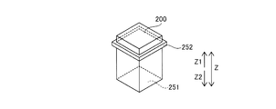
- the bottom surface (251) which can pass through the through hole (33) of the reagent container holder (30), and the through hole (33) between the bottom surface and the top surface And an intermediate side surface (252) having an outer periphery larger than the outer periphery.
- the reagent container (200) can be easily installed in the reagent container holder (30) by inserting the reagent container (200) from the through hole (33) of the reagent container holder (30).
- the reagent container holder (30) is circumferentially installed in a reagent container holder (30) having a circular outer peripheral edge.
- the plurality of reagent containers (200) can be circumferentially arranged in the circular reagent container holder (30) and compactly accommodated.
- the reagent container holder (30) is positioned and installed. According to this structure, the reagent container (200) can be accurately disposed at a predetermined position of the reagent container holder (30), and the reagent container (200) moves relative to the reagent container holder (30). Can be suppressed.
- the reagent is a capture substance that binds to a target substance in a sample using an antigen-antibody reaction, a solid phase carrier that binds the capture substance, and an antigen-antibody reaction. Includes any of the labeled substances that are used to bind to the target substance.
- the capture substance, the solid phase carrier or the labeling substance used for the immunoassay can be efficiently kept cold or kept warm.
- the sample measurement apparatus 100 is an apparatus for measuring a measurement sample prepared by adding a predetermined reagent to a sample collected from a subject.
- the subject is primarily human but may be other animals besides human.
- the sample measurement device 100 performs, for example, measurement for clinical examination or medical research of a sample collected from a patient.
- the sample is a sample of biological origin.
- a sample derived from a living body may be subjected to a predetermined pretreatment on a fluid such as blood (whole blood, serum or plasma), urine, or other body fluid collected from a subject, or collected fluid or blood. It is the obtained liquid etc.
- the sample may be, for example, a part of tissue of the subject, cells, etc. other than the liquid.
- the sample measuring device 100 detects a predetermined target component contained in a sample.
- the target component may include, for example, a predetermined component, a cell or a tangible component in a blood or urine sample.
- the component of interest may be nucleic acids such as DNA (deoxyribonucleic acid), cells and intracellular substances, antigens or antibodies, proteins, peptides and the like.
- the sample measuring device 100 may be a blood cell counting device, a blood coagulation measuring device, an immunoassay device, a urinary tangible component measuring device or the like, or a measuring device other than these.
- the sample measuring device 100 is an immunoassay device that detects an analyte in a sample using an antigen-antibody reaction.
- the immunoassay device detects, for example, an antigen or antibody contained in blood, a protein, a peptide or the like as a target component.
- the immunoassay device acquires serum or plasma as a sample, and quantitatively or qualitatively measures an antigen, an antibody or the like contained in the sample.
- the antigen-antibody reaction includes not only a reaction between an antigen and an antibody but also a reaction using a specific binding substance such as an aptamer. Aptamers are nucleic acid molecules or peptides that are synthesized to bind specifically to a specific substance.
- the sample measurement apparatus 100 adds a predetermined one or more kinds of reagents to a sample to prepare a measurement sample.
- the reagent is set in the sample measurement apparatus 100 in a state of being accommodated in a bottle-shaped reagent container 200.
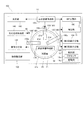
- the sample measurement apparatus 100 includes a measurement unit 10, a reagent storage 20, and a reagent container holder 30.
- the reagent stored in the reagent container 200 of the reagent storage 20 is used for an immunoassay.
- the reagent is any of a capture substance that binds to a target substance in a sample using an antigen-antibody reaction, a solid phase carrier that binds to the capture substance, and a labeling substance that binds to a target substance using an antigen-antibody reaction. including.
- the measurement unit 10 measures a sample using a reagent. Specifically, the measurement unit 10 adds the reagent of the reagent container 200 to the sample to adjust the measurement sample, and measures the sample. In addition, the measurement unit 10 is configured to detect a component contained in the measurement sample prepared by the sample and the reagent.
- the method of detecting the target component by the measuring unit 10 is not limited, and a method corresponding to the target component such as a chemical method, an optical method, or an electromagnetic method can be adopted.
- the measurement unit 10 measures, for example, the presence or absence of the target component, the number or amount of the target component, the concentration or the abundance ratio of the target component, and the like based on the detection result.
- the reagent storage 20 stores a reagent container 200 in which a reagent is stored.
- the reagent storage 20 cools or keeps the reagent at a predetermined temperature.
- the reagent storage 20 cools the reagent to a predetermined temperature. That is, the temperature in the reagent storage 20 is kept lower than the temperature outside the reagent storage 20.
- the reagent container holder 30 is disposed in the reagent storage 20. Further, the reagent container holder 30 can hold a plurality of reagent containers 200. The reagent container holder 30 suspends and holds the reagent container 200 containing the reagent. Specifically, the reagent container holder 30 has a plurality of holders 31 for holding the reagent container 200. Further, the reagent container 200 is set in the reagent container holder 30 automatically by the sample measuring apparatus 100 or manually by the user.
- the reagent container holder 30 holds the reagent container 200 by suspending it in a mode in which an engaging portion (not shown) provided at a predetermined position of the reagent container 200 is hooked to a supporting portion of the reagent container holder 30. Good.
- the reagent container holder 30 is formed in the flat shape extended horizontally.
- the reagent container 200 can be disposed so as to protrude from the reagent container holder 30 into the reagent storage 20 without covering the reagent container 200 with the reagent container holder 30.
- the reagent container 200 can be exposed and disposed in the space in the reagent storage 20, so that the cooling efficiency or heating efficiency of the reagent can be improved.
- the reagent can be efficiently kept cold or kept warm.
- the number of parts can be reduced as compared with the case where box-like small compartments are provided for each reagent container 200.
- the device configuration can be simplified and miniaturized.
- the reagent container 200 can be suspended and held by the reagent container holder 30, the reagent container 200 can be stably held. As a result, when suctioning the reagent from the reagent container 200, the suction tube can be correctly inserted into the reagent container 200.
- the reagent container holder 30 has, for example, a circular shape in plan view.
- the reagent container holder 30 can arrange a plurality of reagent containers 200 in a circumferential shape. That is, the plurality of holders 31 of the reagent container holder 30 are arranged circumferentially.
- the reagent container holder 30 may have a shape other than a circular shape.
- the reagent container holder 30 may be formed in a rectangular shape in plan view.
- a plurality of reagent containers 200 may be arranged linearly.
- the reagent container holder 30 may be provided with a plurality of holding portions 31 arranged in a single circular shape, or even if a plurality of holding portions 31 arranged in a double circular shape are provided. Good.
- the reagent container holder 30 may be provided with a plurality of holding portions 31 arranged in a triple or more circular shape.
- the sample measurement method includes the following steps (1) to (2).
- (1) The reagent container 200 containing the reagent is suspended and installed in the reagent container holder 30.
- the sample is measured using the reagent in the reagent storage 20.
- the reagent container 200 containing the reagent is suspended and installed in the reagent container holder 30.
- the reagent container 200 can be disposed so as to protrude from the reagent container holder 30 into the reagent storage 20 without being covered by the reagent container holder 30.
- the reagent container 200 can be exposed and disposed in the space in the reagent storage 20, so that the cooling efficiency or heating efficiency of the reagent can be improved.
- the reagent can be efficiently kept cold or kept warm.
- the number of parts can be reduced as compared with the case where box-like small compartments are provided for each reagent container 200.
- the device configuration can be simplified and miniaturized. As a result, it is possible to provide an analyte measurement method capable of efficiently keeping cold or keeping the reagent cool and suppressing an increase in the number of parts of the device.
- the sample measurement apparatus 100 is an immunoassay apparatus that detects an analyte in a sample using an antigen-antibody reaction.
- the sample measurement apparatus 100 includes a measurement unit 10, a reagent storage 20, and a reagent container holder 30. Further, in the configuration example of FIG. 2, the sample measurement apparatus 100 includes a housing 110, a sample transport unit 120, a sample dispensing unit 130, a reaction container supply unit 140, a reaction container transfer unit 150, and a reaction unit 160. And a reagent container transfer unit 170, a BF separation unit 180, and a reagent dispensing unit 190.
- the measurement unit 10 includes a detection unit 11 and a control unit 12.
- the housing 110 has a box-like shape that can accommodate each part of the sample measurement device 100 inside.
- the housing 110 may be configured to accommodate each part of the sample measurement apparatus 100 on a single hierarchy, or has a hierarchical structure in which a plurality of layers are provided in the vertical direction. It may be allocated and arranged in each hierarchy.
- the sample transport unit 120 is configured to transport a sample collected from a subject to a suction position by the sample dispensing unit 130.
- the sample transport unit 120 can transport a rack in which a plurality of test tubes containing a sample are provided to a predetermined sample suction position.
- the sample dispensing unit 130 aspirates the sample transported by the sample transport unit 120 and dispenses the aspirated sample into the reaction container 40.
- the sample dispensing unit 130 includes a pipette connected to a fluid circuit for performing aspiration and discharge, and a moving mechanism for moving the pipette.
- the sample dispensing unit 130 mounts the dispensing tip set in the tip supply unit (not shown) on the tip of the pipette, and aspirates a predetermined amount of the sample in the transferred test tube into the dispensing tip.
- the sample dispensing unit 130 dispenses the aspirated sample into the reaction container 40 disposed at a predetermined sample dispensing position. After dispensing, the sample dispensing unit 130 removes the dispensing tip from the tip of the pipette and discards it.
- the reaction container supply unit 140 stores a plurality of reaction containers 40.
- the reaction container supply unit 140 can supply the reaction containers 40 one by one to the reaction container transfer unit 150 at a predetermined reaction container supply position.
- the reaction container transfer unit 150 transfers the reaction container 40.
- the reaction container transfer unit 150 acquires the reaction container 40 from the reaction container supply position, and transfers the reaction container 40 to each processing position of the sample dispensing unit 130, the reagent dispensing unit 190, the reaction unit 160, the detection unit 11, etc. Do.
- the reaction container transfer unit 150 is constituted of, for example, a catcher for holding the reaction container 40 or a holding unit having an installation hole of the reaction container 40, and a moving mechanism for moving the catcher or holding unit.
- the moving mechanism moves in one or more axial directions, for example, by one or more linear movable linear moving mechanisms.
- the movement mechanism may include an arm mechanism that horizontally rotates about a rotation axis, and an articulated robot mechanism.
- One or more reaction container transfer units 150 are provided.
- the reaction unit 160 includes a heater and a temperature sensor, holds the reaction container 40, and heats and reacts the sample contained in the reaction container 40. The heating causes the sample and the reagent contained in the reaction container 40 to react.
- One or more reaction units 160 are provided in the housing 110.
- the reaction unit 160 may be fixedly installed in the housing 110 or may be movably provided in the housing 110. When the reaction unit 160 is configured to be movable, the reaction unit 160 can also function as part of the reaction container transfer unit 150.
- the reagent container transfer unit 170 can transfer the reagent container 200.
- the reagent container transfer unit 170 can lift the reagent container 200 by a hand mechanism (not shown) and can set each in the holding unit 31 of the reagent container holder 30.
- the BF separation unit 180 has a function of performing a BF separation process to separate the liquid phase and the solid phase from the reaction vessel 40.
- the BF separation unit 180 includes one or more processing ports each capable of installing the reaction container 40.
- the processing port includes a magnetic source 182 (see FIG. 16) for collecting magnetic particles contained in the R2 reagent, and a washing unit 181 (see FIG. 16) for suctioning a liquid phase and supplying a washing solution. It is provided.
- the BF separation unit 180 sucks the liquid phase in the reaction container 40 by the washing unit 181 and supplies the washing solution in a state where the magnetic particles on which an immune complex described later is formed are collected.
- the cleaning unit 181 includes a liquid phase suction passage and a washing liquid discharge passage, and is connected to a fluid circuit (not shown). Thereby, unnecessary components contained in the liquid phase can be separated and removed from the conjugate of the immune complex and the magnetic particles.
- the reagent dispensing unit 190 aspirates the reagent in the reagent container 200, and dispenses the aspirated reagent into the reaction container 40.
- the reagent dispensing unit 190 can move the aspiration tube 190a for aspirating and discharging the reagent horizontally between the reagent aspirating position and the reagent dispensing position.
- the reagent dispensing unit 190 can move the suction tube 190 a downward to enter the inside of the reagent container 200.
- the reagent dispensing unit 190 can move the aspiration tube 190 a downward to retract the aspiration tube 190 a to the upper position of the reagent container 200.
- the suction tube 190a is connected to a fluid circuit (not shown), sucks a predetermined amount of reagent from the reagent container 200, and dispenses the reagent to the reaction container 40 transferred to the reagent dispensing position.
- the suction pipe 190a is connected to the liquid level sensor.
- the liquid level sensor is connected to the control unit 12, and when the reagent is sucked from the reagent container 200, the liquid level sensor detects the liquid level of the reagent based on the change in capacitance due to the contact between the liquid level of the reagent and the suction pipe 190a. And outputs the detection result to the control unit 12. Further, the control unit 12 monitors the amount of movement of the suction pipe 190 a by monitoring the amount of movement of the reagent dispensing unit 190.
- the reagent dispensing unit 190 includes a first reagent dispensing unit 191 for dispensing the R1 reagent, and a second reagent dispensing unit 192 for dispensing the R2 reagent. And a third reagent dispensing unit 193 for dispensing the R3 reagent. Further, the reagent dispensing unit 190 includes a fourth reagent dispensing unit 194 for dispensing the R4 reagent and a fifth reagent dispensing unit 195 for dispensing the R5 reagent.
- the first reagent dispensing section 191 can move the suction pipe 190a between the innermost hole 21d for aspirating the R1 reagent and a predetermined R1 reagent dispensing position.
- the second reagent dispensing unit 192 can move the suction pipe 190a between the hole 21d on the outermost circumferential side for sucking the R2 reagent and a predetermined R2 reagent dispensing position.
- the third reagent dispensing unit 193 can move the suction pipe 190a between the hole 21d at the radial intermediate position for sucking the R3 reagent and a predetermined R3 reagent dispensing position.
- the fourth reagent dispensing unit 194 and the fifth reagent dispensing unit 195 are connected to a reagent container (not shown) containing R4 reagent and R5 reagent, respectively, through a liquid transfer tube, and the reaction container transfer unit 150 The reagent can be discharged into the reaction container 40 transferred by the reagent container (not shown) containing R4 reagent and R5 reagent, respectively, through a liquid transfer tube, and the reaction container transfer unit 150 The reagent can be discharged into the reaction container 40 transferred by the
- the detection unit 11 includes a light detector 11a (see FIG. 16) such as a photomultiplier tube.
- the detection unit 11 measures the amount of the antigen contained in the sample by acquiring light generated in the reaction process of the light-emitting substrate with the labeled antibody that binds to the antigen of the sample subjected to various treatments. Do.
- the control unit 12 includes a processor 12a such as a CPU, and a storage unit 12b such as a ROM, a RAM, and a hard disk.
- the processor 12a functions as a control unit of the sample measurement device 100 by executing the control program stored in the storage unit 12b.
- the control unit 12 controls the operation of each unit of the sample measurement apparatus 100 described above. Further, the control unit 12 measures the result detected by the detection unit 11.
- the sample measurement apparatus 100 includes a box-like reagent storage 20 for storing the reagent container holder 30.
- the reagent container holder 30 is provided in a case 21 having a heat insulation function of the reagent storage 20.
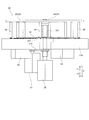
- the reagent storage 20 has a reagent container holder 30 and a cooling mechanism 22 in a case 21 and cools the reagent in the reagent container 200 set in the reagent container holder 30 to a constant temperature suitable for storage.
- the reagent storage 20 arranges the reagent container holder 30 in the reagent storage 20 so as to store a plurality of reagent containers 200.
- the case 21 has an internal space partitioned by a circular cover 21 a and a bottom surface 21 b and a cylindrical side surface 21 c.
- the cover 21a, the bottom surface 21b and the side surface 21c contain a heat insulating material and thermally insulate the inside and the outside of the case 21.
- the cover 21a, the bottom 21b and the side 21c contain a foam material. Thereby, the reagent container 200 can be stored cold.
- the cover 21a covers the top of the reagent container (200).
- the cover 21a has a disk shape.
- the cover 21 a has an outer periphery larger than the outer periphery of the reagent storage 20.
- the upper portion of the reagent storage 20 can be reliably covered by the cover 21a, so that the plurality of reagent containers 200 stored in the reagent storage 20 can be more efficiently cooled or kept warm.
- the reagent storage 20 has a hole 21 d for the reagent dispensing unit 190 to enter the inside of the reagent storage 20.
- the hole 21 d is provided in the cover 21 a. Further, a plurality of holes 21 d are provided.
- the cooling mechanism 22 includes, for example, a cooling unit including a Peltier element and the like, and fins for transferring heat.
- a plurality of cooling mechanisms 22 are provided near the bottom surface 21 b of the reagent storage 20. The air in the reagent storage 20 is sent to the cooling mechanism 22 by a fan, and the cooled air is circulated in the reagent storage 20.
- the reagent container holder 30 can hold a plurality of reagent containers 200.
- the reagent container holder 30 includes a plurality of holders 31.
- the reagent container holder 30 includes a hanging portion 32 which suspends and holds the reagent container 200.
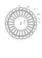
- the reagent container holder 30 also includes a through hole 33. Further, the reagent container holder 30 is formed to align and hold a plurality of reagent containers 200 in the circumferential direction.
- the reagent container holder 30 includes a first reagent container holder 34 and a second reagent container holder 35.
- the reagent container holder 30 also includes a first drive unit 36 that rotates the first reagent container holder 34 and a second drive unit 37 that rotates the second reagent container holder 35. Further, the reagent container holder 30 includes a rotary table 38 and a connecting member 39.
- the reagent container holder 30 is formed in a flat shape extending horizontally. Thereby, it is possible to efficiently keep the reagent cold or warm and to suppress an increase in the number of parts.
- the reagent container holder 30 is configured to hold the reagent container 200 so that 50% or more of the surface of the reagent container 200 is exposed to the space in the reagent storage 20.
- 50% or more of the surface of the reagent container 200 can be exposed and disposed in the space in the reagent storage 20, so that the cooling efficiency or heating efficiency of the reagent can be further improved.
- the reagent container holder 30 is configured to hold the reagent container 200 such that 80% or more of the surface of the reagent container 200 is exposed to the space in the reagent storage 20. Thereby, 80% or more of the surface of the reagent container 200 can be exposed and disposed in the space in the reagent storage 20, so that the cooling efficiency or heating efficiency of the reagent can be effectively improved.
- the reagent container holder 30 suspends and holds the reagent container 200 by the suspending unit 32.
- the suspending unit 32 suspends and holds the reagent container 200 by the suspending unit 32.
- the upper part of the reagent container 200 can be supported by the reagent container holder 30, the lower part of the reagent container 200 in which the reagent is accumulated can be reliably exposed in the reagent storage 20.
- the reagent container 200 can be stably held when the reagent is sucked from above.
- the reagent container holder 30 is configured to hold the plurality of reagent containers 200 such that the exposed portions of the adjacent reagent containers 200 face each other. That is, the space between the adjacent reagent containers 200 is open in the reagent storage 20 except for the height position supported by the flat-shaped reagent container holder 30. Thereby, since a member is not arrange
- the reagent container holder 30 is configured such that a plurality of reagent containers 200 are arranged circumferentially, and has a substantially circular outer peripheral edge.
- the plurality of reagent containers 200 can be circumferentially arranged on the substantially circular reagent container holder 30 and compactly accommodated in the storage.
- the first reagent container holder 34 of the reagent container holder 30 is formed in a circular shape.
- the second reagent container holder 35 is formed in an annular shape so as to surround the first reagent container holder 34 in a plan view. That is, the second reagent container holder 35 is disposed around the first reagent container holder 34.
- the first reagent container holder 34 and the second reagent container holder 35 are arranged concentrically and can rotate independently of each other. Further, the first reagent container holder 34 and the second reagent container holder 35 are disposed at substantially the same height position.
- the first reagent container holder 34 on the inner circumferential side can hold the plurality of reagent containers 200 circumferentially.
- the second reagent container holder 35 on the outer peripheral side can hold the plurality of reagent containers 200 in a circumferential shape.
- the reagent container holder 30 positions and fixes the reagent container 200 by the holding unit 31.
- the reagent container 200 can be accurately disposed at a predetermined position of the reagent container holder 30, and the movement of the reagent container 200 relative to the reagent container holder 30 can be suppressed.
- the reagent container holder 30 is disposed in the region on the upper half side of the reagent storage 20 in the vertical direction (Z direction).
- the upper half portion of the reagent container 200 can be supported by the reagent container holder 30, so that the lower portion of the reagent container 200 in which the reagent is accumulated can be reliably exposed in the reagent storage 20.
- the reagent container 200 can be stably held when the reagent is suctioned from above.
- the first drive unit 36 is disposed outside the reagent storage 20. Specifically, the first drive unit 36 is disposed outside the lower side of the reagent storage 20.
- the first drive unit 36 rotates the first support 361.
- the first support portion 361 supports the first reagent container holder 34. That is, the first drive unit 36 rotationally drives the first reagent container holder 34 via the first support unit 361.
- the first drive unit 36 is, for example, a drive source such as a stepping motor or a servomotor.
- the first drive unit 36 rotates the first reagent container holder 34 by rotationally driving the first support 361 connected to the center of the first reagent container holder 34 and extending vertically.
- the lower end portion of the first support portion 361 is connected to the first drive portion 36, and the upper end portion is connected to the center of the first reagent container holder 34.
- the first reagent container holder 34 can be easily rotated and moved by the first drive unit 36 disposed outside the reagent storage 20. Further, by providing the first drive unit 36 outside the reagent storage 20, interference of the first drive unit 36 with the reagent container 200 held by the first reagent container holder 34 can be suppressed, and The heat of the first driving unit 36 can be suppressed from being transmitted to the inside of the reagent storage 20.
- the second drive unit 37 is disposed outside the reagent storage 20. Specifically, the second drive unit 37 is disposed outside the lower side of the reagent storage 20. The second drive unit 37 rotates the second support unit 371. The second support portion 371 supports the rotary table 38. The rotary table 38 supports the second reagent container holder 35 via a plurality of connecting members 39. That is, the second drive unit 37 rotationally drives the second reagent container holder 35 via the second support 371, the rotary table 38 and the connection member 39.
- the second drive unit 37 is a drive source such as a stepping motor or a servomotor, for example.
- the second drive unit 37 rotates the second reagent container holder 35 by rotationally driving the rotary table 38 connected to the second reagent container holder 35 via the transmission mechanism 372.
- the rotary table 38 is connected to the transmission mechanism 372 via a coupling and a second support 371.
- the rotary table 38 and the second support portion 371 have a through hole at the center through which the first support portion 361 passes, and rotate independently of the first support portion 361.
- the second drive unit 37 and the first drive unit 36 respectively rotate and drive the second reagent container holder 35 on the outer peripheral side and the first reagent container holder 34 on the inner peripheral side.
- the second reagent container holder 35 can be rotationally moved independently of the first reagent container holder 34.
- interference of the second drive unit 37 with the reagent container 200 held by the second reagent container holder 35 can be suppressed, and The heat of the second driving unit 37 can be suppressed from being transmitted to the inside of the reagent storage 20.
- the reagent container 200 includes a reagent container 201 and a reagent container 202.
- the reagent container 201 includes a container main body 232 that stores an R2 reagent described later.
- the reagent container 202 is a multiple-type reagent container in which a container main body 233 containing an R3 reagent described later and a container main body 231 containing an R1 reagent are connected in one set.
- the reagent container 201 and the reagent container 202 each include an upper cover 240 that covers the top of the container body.
- the upper cover 240 has an outer peripheral portion 241 along the side surface of the container main body so as to cover a part of the side surface of the container main body, and a contact portion for engaging the reagent container holder 30 with the lower end portion of the outer peripheral portion 241 242 are provided.
- the contact portion 242 is supported by the holding portion 31 of the reagent container holder 30.
- the contact portion 242 contacts the reagent container holder 30.
- the contact part 242 has an outer periphery larger than the outer periphery of a container main body.
- the upper cover 240 has a gripped portion 243. Further, the upper cover 240 is provided with a lid 220 which can be opened and closed.
- the lids 220 of the plurality of reagent containers 201 held side by side in the circumferential direction are arranged side by side in the same circumferential shape.
- the reagent containers 202 of each of the plurality of reagent containers 202 held side by side in the circumferential direction are arranged side by side in the same circumferential shape.
- the container bodies 231 and 233 of each of the plurality of reagent containers 202 held side by side in the circumferential direction are respectively arranged in the same circumferential shape.
- each of the container body 232, the container body 233, and the container body 231 is disposed at different positions in the radial direction. Therefore, as shown in FIG.
- the cover 21a of the case 21 is a circle in which the holes 21d corresponding to the suction positions of the R1 reagent to the R3 reagent are arranged and the lids 220 of the corresponding reagent containers 200 are arranged. It is provided in three places so that it may overlap with the predetermined position on circumference.
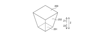
- the reagent container 200 has an intermediate side surface having a bottom surface 251 which can pass through the through hole 33 of the reagent container holder 30 and an outer periphery larger than the outer periphery of the through hole 33 between the bottom surface and the top surface. And a unit 252.
- the reagent container 200 can be easily installed in the reagent container holder 30 by inserting the reagent container 200 from the through hole 33 of the reagent container holder 30.
- the intermediate side surface portion 252 of the reagent container 200 can be brought into contact with the edge portion of the through hole 33 of the reagent container holder 30, the vertical direction of the reagent container 200 can be positioned with high accuracy. That is, the reagent container 200 can be set to the reagent container holder 30 without rattling. Also, the reagent container 200 can be easily set to the reagent container holder 30.
- the through hole 33 of the reagent container holder 30 includes a lower opening 33a and an upper opening 33b provided above the lower opening 33a and having an outer periphery larger than the outer periphery of the lower opening 33a. That is, the hanging portion 32 includes the lower opening 33a and the upper opening (33b) provided above the lower opening 33a and having an outer periphery larger than the outer periphery of the lower opening 33a. Further, the bottom surface 251 of the reagent container 200 has an outer periphery smaller than the lower opening 33a, and the middle side surface 252 of the reagent container 200 has an outer periphery having substantially the same size as the upper opening 33b.
- the outer periphery of the upper opening 33b is larger than the outer periphery of the bottom surface 251 of the reagent container 200. Therefore, as shown in FIG. 9A, the reagent container 200 can be easily inserted into the upper opening 33b. Further, since the reagent container 200 inserted from the upper opening 33b can be easily guided to the lower opening 33a following the upper opening 33b, the reagent container 200 can be easily inserted into the lower opening 33a. Further, since the outer periphery of the upper opening 33b has substantially the same size as the outer periphery of the middle side surface 252 of the reagent container 200, as shown in FIG. 9B, the middle side surface 252 is fitted into the upper opening 33b. Thus, the reagent container 200 can be easily fixed to the reagent container holder 30.
- the gap between the lower opening 33a and the reagent container 200 is, for example, about 1 mm to 2 mm per side.
- the gap between the upper opening 333 b and the reagent container 200 is, for example, about 0.1 mm on one side.
- the through hole 33 may have only a part of play.
- the clearance between the through hole 33 and the reagent container 200 may be large near the corner. Thereby, it is possible to suppress that the reagent container 200 does not enter the through hole 33 due to dimensional error.
- the upper opening 33b has a tapered shape that tapers toward the lower opening 33a.
- the reagent container 200 can be more easily guided from the upper opening 33 b to the lower opening 33 a, so that the reagent container 200 can be easily installed in the reagent container holder 30. That is, as shown in FIG. 10A, the reagent container 200 is guided toward the center of the through hole 33 by the tapered shape of the upper opening 33 b. Then, as shown in FIG. 10B, the middle side surface portion 252 of the reagent container 200 is fitted into the upper opening 33b and positioned.
- the tapered shape of the upper opening 33b has, for example, an inclination angle of about 15 degrees to 60 degrees with respect to the vertical direction.
- the reagent container 200 may be inclined so that the side surface extends upward, as shown in FIG. As a result, the bottom surface 251 passes through the through hole 33, and at the predetermined height position, the intermediate side surface portion 252 is fitted into the through hole 33 without any gap, and the reagent container 200 is installed. Further, as shown in FIG. 12, the reagent container 200 may be provided with the intermediate side surface portion 252 projecting from the side surface.
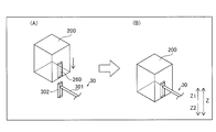
- the reagent container 200 may also have an engaging portion 260 as shown in FIG.
- the reagent container holder 30 may have the support portion 301 and the engaged portion 302.
- the reagent container 200 is held by the reagent container holder 30 by the engagement portion 260 engaging with the engaged portion 302 and being hooked.
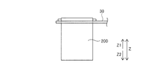
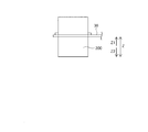
- the reagent container holder 30 may support the upper portion of the reagent container 200, as shown in FIG. Further, as shown in FIG. 15, the reagent container holder 30 may support a portion near the central portion in the vertical direction of the reagent container 200.
- the immunoassay is performed using the R1 reagent to the R5 reagent.
- An example in which the test substance 81 is a hepatitis B surface antigen (HBsAg) will be described as an example of the immunoassay with reference to FIG.
- the sample containing the test substance 81 and the R1 reagent are dispensed into the reaction container 40.
- the R1 reagent is dispensed into the reaction container 40 by the first reagent dispensing unit 191, and the sample is dispensed into the reaction container 40 by the sample dispensing unit 130.
- the R1 reagent contains a capture substance 84, and reacts with and binds to the test substance 81.
- the capture substance 84 includes a binding substance for binding the capture substance 84 to the solid phase carrier 82 contained in the R2 reagent.
- a combination of, for example, biotin and avidins, hapten and anti-hapten antibody, nickel and histatidine tag, and glutathione and glutathione-S-transferase can be used to bind the binding substance to the solid phase carrier.
- "Avidins” is meant to include avidin and streptavidin.
- the capture substance 84 is a biotin-modified antibody (biotin antibody). That is, the capture substance 84 is modified with biotin as a binding substance. After dispensing the sample and the R1 reagent, the sample in the reaction container 40 is heated to a predetermined temperature in the reaction unit 160, whereby the capture substance 84 and the test substance 81 are bound.
- biotin antibody biotin antibody
- the R2 reagent is dispensed into the reaction container 40 by the second reagent dispensing unit 192.
- the R2 reagent contains a solid phase carrier 82.
- the solid support 82 binds to the binding substance of the capture substance 84.
- the solid support 82 is, for example, magnetic particles (StAvi-bound magnetic particles) on which streptavidin binding to biotin is immobilized. Streptavidin of the StAvi-bound magnetic particles react with and bind to the binding substance biotin.
- the sample in the reaction container 40 is heated to a predetermined temperature in the reaction unit 160. As a result, the test substance 81 and the capture substance 84 bind to the solid phase carrier 82.
- the test substance 81 and the capture substance 84 formed on the solid phase carrier 82 and the unreacted capture substance 84 are separated by the primary BF separation processing by the BF separation unit 180.
- the BF separation unit 180 is used to attract the liquid phase by the cleaning unit 181 in the magnetic collection state by the magnetic force source 182, discharge the cleaning solution, Each step of stirring in the state is performed one or more times. Unnecessary components such as unreacted capture substance 84 are removed from the reaction vessel 40 by the primary BF separation process. In the primary BF separation process, the process proceeds to the next step while the liquid phase in the reaction vessel 40 is finally aspirated.
- the R3 reagent is dispensed into the reaction container 40 by the third reagent dispensing unit 193.
- the R3 reagent contains a labeling substance 83, and reacts with and binds to the test substance 81.
- the sample in the reaction container 40 is heated to a predetermined temperature in the reaction unit 160.
- an immune complex 85 including the test substance 81, the labeling substance 83, and the capture substance 84 is formed.
- the labeling substance 83 is an ALP (alkaline phosphatase) labeled antibody.
- the immune complex 85 formed on the solid phase carrier 82 and the unreacted labeled substance 83 are separated by the secondary BF separation process.
- the BF separation unit 180 executes one or more steps of suction of the liquid phase in the magnetic collection state by the magnetic force source 182, discharge of the cleaning liquid, and stirring in the non-magnetic collection state. Unnecessary components such as unreacted labeled substance 83 are removed from the reaction vessel 40 by the secondary BF separation process. In the second BF separation process, the process proceeds to the next step while the liquid phase in the reaction vessel 40 is finally aspirated.
- the R4 reagent and the R5 reagent are dispensed into the reaction container 40 by the fourth reagent dispensing unit 194 and the fifth reagent dispensing unit 195, respectively.
- the R4 reagent contains a buffer.
- the immune complex 85 bound to the solid phase carrier 82 is dispersed in the buffer.
- the R5 reagent contains a chemiluminescent substrate.
- the buffer solution contained in the R4 reagent has a composition that promotes the reaction of the label (enzyme) of the labeling substance 83 contained in the immune complex 85 with the substrate.
- the sample in the reaction container 40 is heated to a predetermined temperature in the reaction unit 160. Light is generated by reacting the substrate with the label, and the intensity of the generated light is measured by the light detector 11 a of the detection unit 11.
- the control unit 12 measures the content of the test substance 81 in the sample and the like based on the detection signal of the detection unit 11.
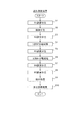
- step S1 the control unit 12 causes the reaction container transfer unit 150 to transfer the reaction container 40 to the R1 reagent dispensing position.
- the control unit 12 causes the first reagent dispensing unit 191 to dispense the R1 reagent into the reaction container 40.
- step S2 the sample is dispensed into the reaction container 40.
- the control unit 12 causes the sample dispensing unit 130 to aspirate the sample from the test tube on the sample transport unit 120.
- the control unit 12 causes the sample dispensing unit 130 to dispense the aspirated sample into the reaction container 40.
- the sample dispensing unit 130 is controlled to discard the dispensing tip to a waste port (not shown).
- the sample dispensing unit 130 replaces the unused dispensing tip with an unused dispensing tip every time the dispensing operation is performed via the dispensing tip.
- step S3 the control unit 12 causes the reaction container transfer unit 150 to transfer the reaction container 40 to the R2 reagent dispensing position, and causes the second reagent dispensing unit 192 to dispense the R2 reagent into the reaction container 40.
- the control unit 12 causes the reaction container transfer unit 150 to transfer the reaction container 40 to the reaction unit 160.
- the reaction container 40 is heated in the reaction unit 160 for a predetermined time.
- step S4 the control unit 12 causes the BF separation unit 180 to execute the primary BF separation process.
- the control unit 12 causes the reaction container transfer unit 150 to transfer the reaction container 40 to the BF separation unit 180.
- the BF separation unit 180 is controlled to perform the primary BF separation process (see FIG. 16) on the sample in the reaction vessel 40 to remove the liquid component.
- step S5 the control unit 12 transfers the reaction container 40 to the R3 reagent dispensing position by the reaction container transfer unit 150, and causes the third reagent dispensing unit 193 to dispense the R3 reagent into the reaction container 40.
- the control unit 12 causes the reaction container transfer unit 150 to transfer the reaction container 40 to the reaction unit 160.
- the reaction container 40 is heated in the reaction unit 160 for a predetermined time.
- step S6 the control unit 12 causes the BF separation unit 180 to execute the secondary BF separation process.
- the control unit 12 causes the reaction container transfer unit 150 to transfer the reaction container 40 to the BF separation unit 180.
- the BF separation unit 180 is controlled to perform secondary BF separation processing (see FIG. 16) on the sample in the reaction vessel 40 to remove the liquid component.
- step S7 the R4 reagent is dispensed into the reaction container 40.
- the control unit 12 causes the reaction container transfer unit 150 to transfer the reaction container 40 to the R4 reagent dispensing position, and causes the fourth reagent dispensing unit 194 to dispense the R4 reagent into the reaction container 40.
- step S8 the R5 reagent is dispensed into the reaction container 40.
- the control unit 12 causes the reaction container transfer unit 150 to transfer the reaction container 40 to the R5 reagent dispensing position and causes the fifth reagent dispensing unit 195 to dispense the R5 reagent into the reaction container 40.
- the control unit 12 causes the reaction container transfer unit 150 to transfer the reaction container 40 to the reaction unit 160.
- the reaction container 40 is heated in the reaction unit 160 for a predetermined time.
- step S9 a detection process of the immune complex 85 is performed.
- the control unit 12 causes the reaction container transfer unit 150 to transfer the reaction container 40 to the detection unit 11.
- the detection unit 11 measures the intensity of light generated by reacting the substrate with the label.
- the detection result of the detection unit 11 is output to the control unit 12.
- step S10 the reaction container transfer unit 150 is controlled so as to take out the reaction container 40 subjected to the measurement processing from the detection unit 11 and discard the reaction container 40 into a waste port (not shown).
- the measurement processing operation by the sample measurement apparatus 100 is performed.
Landscapes
- Chemical & Material Sciences (AREA)
- Health & Medical Sciences (AREA)
- General Health & Medical Sciences (AREA)
- Life Sciences & Earth Sciences (AREA)
- Analytical Chemistry (AREA)
- Biochemistry (AREA)
- Physics & Mathematics (AREA)
- General Physics & Mathematics (AREA)
- Immunology (AREA)
- Pathology (AREA)
- Chemical Kinetics & Catalysis (AREA)
- Clinical Laboratory Science (AREA)
- Medicinal Chemistry (AREA)
- Automatic Analysis And Handling Materials Therefor (AREA)
Abstract
L'invention concerne un dispositif de mesure d'échantillons qui tient efficacement froid ou chaud un réactif et qui supprime des augmentations du nombre de composants, un récipient de réactif et une méthode de mesure d'échantillons. Ledit dispositif de mesure d'échantillons comprend un support de récipient de réactif (30) qui maintient en suspension des récipients de réactif (200) contenant un réactif, et une unité de mesure (10) qui utilise un réactif pour mesurer un échantillon.
Priority Applications (3)
| Application Number | Priority Date | Filing Date | Title |
|---|---|---|---|
| EP18902344.3A EP3745136B1 (fr) | 2018-01-25 | 2018-12-07 | Dispositif de mesure d'échantillons et méthode de mesure d'échantillons |
| CN201880087710.9A CN111630394A (zh) | 2018-01-25 | 2018-12-07 | 受试体测定装置、试剂容器及受试体测定方法 |
| US16/937,769 US12130300B2 (en) | 2018-01-25 | 2020-07-24 | Sample measuring apparatus, reagent container, and method of measuring sample |
Applications Claiming Priority (2)
| Application Number | Priority Date | Filing Date | Title |
|---|---|---|---|
| JP2018010309A JP6959875B2 (ja) | 2018-01-25 | 2018-01-25 | 検体測定装置、試薬容器および検体測定方法 |
| JP2018-010309 | 2018-01-25 |
Related Child Applications (1)
| Application Number | Title | Priority Date | Filing Date |
|---|---|---|---|
| US16/937,769 Continuation US12130300B2 (en) | 2018-01-25 | 2020-07-24 | Sample measuring apparatus, reagent container, and method of measuring sample |
Publications (1)
| Publication Number | Publication Date |
|---|---|
| WO2019146272A1 true WO2019146272A1 (fr) | 2019-08-01 |
Family
ID=67395317
Family Applications (1)
| Application Number | Title | Priority Date | Filing Date |
|---|---|---|---|
| PCT/JP2018/045089 Ceased WO2019146272A1 (fr) | 2018-01-25 | 2018-12-07 | Dispositif de mesure d'échantillons et méthode de mesure d'échantillons |
Country Status (5)
| Country | Link |
|---|---|
| US (1) | US12130300B2 (fr) |
| EP (1) | EP3745136B1 (fr) |
| JP (3) | JP6959875B2 (fr) |
| CN (1) | CN111630394A (fr) |
| WO (1) | WO2019146272A1 (fr) |
Cited By (1)
| Publication number | Priority date | Publication date | Assignee | Title |
|---|---|---|---|---|
| JP2023146770A (ja) * | 2022-03-29 | 2023-10-12 | キヤノンメディカルシステムズ株式会社 | 自動分析装置 |
Families Citing this family (3)
| Publication number | Priority date | Publication date | Assignee | Title |
|---|---|---|---|---|
| CN117470603B (zh) * | 2022-07-21 | 2025-07-18 | 大庆油田有限责任公司 | 一种干酪根制备仪 |
| WO2024218519A1 (fr) * | 2023-04-20 | 2024-10-24 | Ttp Plc. | Cartouche et conteneur de traitement biologique modulaire |
| CN119915591B (zh) * | 2025-04-01 | 2025-06-17 | 成都翼泰生物科技有限公司 | 一种痰液混合分散装置及方法 |
Citations (5)
| Publication number | Priority date | Publication date | Assignee | Title |
|---|---|---|---|---|
| JPH11194133A (ja) * | 1996-09-19 | 1999-07-21 | Abbott Lab | サンプル中の関心項目を決定する構造物を構築する方法 |
| JP2007309740A (ja) * | 2006-05-17 | 2007-11-29 | Olympus Corp | 自動分析装置用の試薬容器 |
| JP2011191117A (ja) * | 2010-03-12 | 2011-09-29 | Sysmex Corp | 分析装置 |
| JP2012254498A (ja) * | 2011-06-09 | 2012-12-27 | Honda Motor Co Ltd | 製品搬送ラックの移動方法及びその移動装置 |
| JP2014119328A (ja) | 2012-12-17 | 2014-06-30 | Hitachi High-Technologies Corp | 試薬保管庫および試薬保管庫を備えた自動分析装置 |
Family Cites Families (15)
| Publication number | Priority date | Publication date | Assignee | Title |
|---|---|---|---|---|
| JPH0250681U (fr) | 1988-09-30 | 1990-04-09 | ||
| JPH0721220Y2 (ja) | 1990-02-08 | 1995-05-17 | 三井製薬工業株式会社 | 撹拌装置 |
| CA2384519C (fr) * | 1991-03-04 | 2006-08-15 | Bayer Corporation | Analyseur automatise |
| US5324481A (en) | 1991-06-03 | 1994-06-28 | Abbott Laboratories | Carousel for assay specimen carrier |
| US5807523A (en) * | 1996-07-03 | 1998-09-15 | Beckman Instruments, Inc. | Automatic chemistry analyzer |
| US6998270B2 (en) | 2001-11-26 | 2006-02-14 | Lab Vision Corporation | Automated tissue staining system and reagent container |
| CN1963527B (zh) * | 2005-11-10 | 2011-12-14 | 深圳迈瑞生物医疗电子股份有限公司 | 全自动生化分析仪及其分析方法 |
| JP4940032B2 (ja) | 2007-06-29 | 2012-05-30 | 株式会社東芝 | 自動分析装置及びその試薬庫 |
| JP5001769B2 (ja) * | 2007-09-28 | 2012-08-15 | 協和メデックス株式会社 | 自動免疫分析装置 |
| JP5634856B2 (ja) | 2010-12-24 | 2014-12-03 | シスメックス株式会社 | 試薬保冷庫及びこれを備えた検体分析装置 |
| US8999241B2 (en) | 2011-03-16 | 2015-04-07 | Sysmex Corporation | Specimen analyzer |
| JP6012728B2 (ja) * | 2012-06-25 | 2016-10-25 | 協和メデックス株式会社 | カセット及び試薬セット |
| CN204374222U (zh) * | 2014-12-17 | 2015-06-03 | 株式会社东芝 | 旋转工作台、试药库及分析装置 |
| JP6166008B2 (ja) * | 2015-03-31 | 2017-07-26 | シスメックス株式会社 | 免疫測定装置 |
| US20190024970A1 (en) * | 2017-07-21 | 2019-01-24 | Franco Sapia | Beverage Cooling Apparatus |
-
2018
- 2018-01-25 JP JP2018010309A patent/JP6959875B2/ja active Active
- 2018-12-07 CN CN201880087710.9A patent/CN111630394A/zh active Pending
- 2018-12-07 WO PCT/JP2018/045089 patent/WO2019146272A1/fr not_active Ceased
- 2018-12-07 EP EP18902344.3A patent/EP3745136B1/fr active Active
-
2020
- 2020-07-24 US US16/937,769 patent/US12130300B2/en active Active
-
2021
- 2021-10-04 JP JP2021163242A patent/JP7186272B2/ja active Active
-
2022
- 2022-11-28 JP JP2022189110A patent/JP7357750B2/ja active Active
Patent Citations (5)
| Publication number | Priority date | Publication date | Assignee | Title |
|---|---|---|---|---|
| JPH11194133A (ja) * | 1996-09-19 | 1999-07-21 | Abbott Lab | サンプル中の関心項目を決定する構造物を構築する方法 |
| JP2007309740A (ja) * | 2006-05-17 | 2007-11-29 | Olympus Corp | 自動分析装置用の試薬容器 |
| JP2011191117A (ja) * | 2010-03-12 | 2011-09-29 | Sysmex Corp | 分析装置 |
| JP2012254498A (ja) * | 2011-06-09 | 2012-12-27 | Honda Motor Co Ltd | 製品搬送ラックの移動方法及びその移動装置 |
| JP2014119328A (ja) | 2012-12-17 | 2014-06-30 | Hitachi High-Technologies Corp | 試薬保管庫および試薬保管庫を備えた自動分析装置 |
Cited By (1)
| Publication number | Priority date | Publication date | Assignee | Title |
|---|---|---|---|---|
| JP2023146770A (ja) * | 2022-03-29 | 2023-10-12 | キヤノンメディカルシステムズ株式会社 | 自動分析装置 |
Also Published As
| Publication number | Publication date |
|---|---|
| EP3745136A1 (fr) | 2020-12-02 |
| JP2023011044A (ja) | 2023-01-20 |
| JP6959875B2 (ja) | 2021-11-05 |
| US12130300B2 (en) | 2024-10-29 |
| JP2021193401A (ja) | 2021-12-23 |
| EP3745136B1 (fr) | 2025-01-22 |
| JP2019128265A (ja) | 2019-08-01 |
| JP7357750B2 (ja) | 2023-10-06 |
| EP3745136A4 (fr) | 2021-11-17 |
| JP7186272B2 (ja) | 2022-12-08 |
| US20200355713A1 (en) | 2020-11-12 |
| CN111630394A (zh) | 2020-09-04 |
Similar Documents
| Publication | Publication Date | Title |
|---|---|---|
| JP7357750B2 (ja) | 試薬容器 | |
| EP2546655B1 (fr) | Instrument et procédé de traitement automatique d'échantillons liquides | |
| JP4558995B2 (ja) | 移送ユニットおよびその移送ユニットを備える自動分析装置 | |
| JP6987653B2 (ja) | 検体測定装置、試薬容器および検体測定方法 | |
| WO2019146273A1 (fr) | Dispositif de mesure d'échantillon et procédé de circulation d'air dans un stockage de réactif | |
| US20200393474A1 (en) | Bf separator, sample analyzer, and bf separation method | |
| WO2018126775A1 (fr) | Dispositif d'analyse automatique et procédé d'analyse d'échantillon | |
| IE913241A1 (en) | Assay or reaction apparatus | |
| US11422142B2 (en) | Reagent container, reagent suction method and sample measuring apparatus | |
| US20190201904A1 (en) | Sample measuring apparatus and sample measuring method | |
| JP5978039B2 (ja) | 自動分析装置 | |
| US20250083143A1 (en) | Examination apparatus | |
| CN117805357A (zh) | 样本分析仪及注液控制方法 |
Legal Events
| Date | Code | Title | Description |
|---|---|---|---|
| 121 | Ep: the epo has been informed by wipo that ep was designated in this application |
Ref document number: 18902344 Country of ref document: EP Kind code of ref document: A1 |
|
| NENP | Non-entry into the national phase |
Ref country code: DE |
|
| ENP | Entry into the national phase |
Ref document number: 2018902344 Country of ref document: EP Effective date: 20200825 |