WO2019146558A1 - Article poreux moulé - Google Patents
Article poreux moulé Download PDFInfo
- Publication number
- WO2019146558A1 WO2019146558A1 PCT/JP2019/001728 JP2019001728W WO2019146558A1 WO 2019146558 A1 WO2019146558 A1 WO 2019146558A1 JP 2019001728 W JP2019001728 W JP 2019001728W WO 2019146558 A1 WO2019146558 A1 WO 2019146558A1
- Authority
- WO
- WIPO (PCT)
- Prior art keywords
- molded body
- dispersed phase
- porous
- porous molded
- holes
- Prior art date
- Legal status (The legal status is an assumption and is not a legal conclusion. Google has not performed a legal analysis and makes no representation as to the accuracy of the status listed.)
- Ceased
Links
Images


Classifications
-
- C—CHEMISTRY; METALLURGY
- C08—ORGANIC MACROMOLECULAR COMPOUNDS; THEIR PREPARATION OR CHEMICAL WORKING-UP; COMPOSITIONS BASED THEREON
- C08J—WORKING-UP; GENERAL PROCESSES OF COMPOUNDING; AFTER-TREATMENT NOT COVERED BY SUBCLASSES C08B, C08C, C08F, C08G or C08H
- C08J9/00—Working-up of macromolecular substances to porous or cellular articles or materials; After-treatment thereof
- C08J9/26—Working-up of macromolecular substances to porous or cellular articles or materials; After-treatment thereof by elimination of a solid phase from a macromolecular composition or article, e.g. leaching out
Definitions
- the present invention relates to a porous molded body.
- a porous molded body As a porous molded body, a film-like porous molded body (hereinafter referred to as a porous film) having a honeycomb structure is known in which a plurality of minute pores are regularly arranged along the film surface. There is.
- the porous film having the honeycomb structure is manufactured by a condensation method (also called a Breath Figure method).
- a condensation method also called a Breath Figure method.
- a cast film is formed by casting a solution containing a hydrophobic material for forming a film, and the film is formed by evaporating the solvent and water droplets after condensation is caused on the cast film.
- the porous film obtained by this condensation method is formed in a state where a very small number of pores form a regular array by using water droplets as a template, for example, a culture carrier (cells for culturing cells) It is useful in medical fields such as culture substrates), adhesion prevention materials, or filtration filters.
- a culture carrier cells for culturing cells
- Patent Document 1 describes a porous film formed of a hydrophilic material and having a larger diameter than that of the porous film produced by the above-described condensation method.
- the porous film of Patent Document 1 is manufactured from an emulsion.
- Patent Document 2 also describes a porous film produced from an emulsion and composed of a hydrophilic material.
- Patent Document 3 describes a reverse opal structure containing cellulose.
- the structure of Patent Document 3 is produced by impregnating a solution containing cellulose into a colloidal crystal obtained from a silica particle or the like having a particle size of 200 nm to 500 nm in the form of a thin film. Since this structure is obtained using a colloidal crystal as a template, the diameter of the pores of the resulting structure is also about the same as the diameter of the colloidal crystal.
- the material to be used is limited to the hydrophobicity from the production method in which water droplets are used as a mold as described above.
- the molded object which can be formed by the dew condensation method is a thin thing called a film.
- the porous film of patent document 2 has a high porosity (ratio of the volume which a void part occupies), the arrangement state of a void part lacks in orderness, and it can not be said that there is regularity. In this respect, if the porous molded body is a three-dimensional solid body thicker than the film and the holes are densely arranged with regularity regardless of the portion, the application of the porous molded body is expanded.
- an object of the present invention is to provide a porous molded body made of a hydrophilic material and in which the pores are densely arranged with regularity regardless of which part.
- the porous molded object of this invention is formed with a hydrophilic material, and has the space
- the air gap is formed by communication between a plurality of spherical holes arranged in a close-packed structure.
- the diameter of the cavity is preferably in the range of 1 ⁇ m to 1 mm.
- the openings are preferably arranged regularly on the surface.
- the openings are preferably formed to have the same diameter.
- the close-packed structure is preferably a hexagonal close-packed structure and / or a cubic close-packed structure.
- the volume fraction of the voids relative to the entire porous molded body is preferably 74% or more.
- the center-to-center length of the holes in contact with each other be smaller than the diameter of the holes.
- the size distribution of the plurality of spherical holes is preferably 5% or less.
- the hydrophilic material is preferably biocompatible. Also preferably, the hydrophilic material is selected from collagen, polyglycolic acid, chitosan and hydroxyapatite and derivatives or mixtures of collagen, polyglycolic acid, chitosan and hydroxyapatite. In addition, the hydrophilic material is preferably biodegradable.
- a porous molded body made of a hydrophilic material and in which the pores are regularly arranged in a dense manner regardless of the portion.
- a porous molded body (hereinafter also referred to as a molded body) 10 which is an example of the present invention is shown in FIG.
- the porous molded body 10 is formed into a cylindrical body, that is, a cylindrical shape having a circular cross section, and the diameter D10 of the bottom surface 10B is 10 mm, and the height H10 is 10 mm.
- the shape and the size are not limited to this example, and the smallest dimension of the three orthogonal dimensions may be more than 1 mm.
- the porous molded body 10 has a void 12 inside thereof, and a plurality of openings 12a are formed on the surface 10S.
- the opening 12a is the opening 12 exposed to the surface 10S. That is, the molded body 10 has the void 12 opened on the surface 10S.
- FIG. 1 in order to avoid complication of a figure, only a part of many opening part 12a is drawn.
- a plurality of spherical cavity portions 13 are connected in the inside of the molded body 10, and the cavity portions 13 constitute an air gap 12.
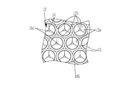
- Each cavity 13 is a virtually partitioned conceptual space, and each cavity 13 and the cavity 12 are defined by a hydrophilic material. That is, the molded body 10 is formed of a hydrophilic material, and the air gaps 12 communicate with each other by the communication holes 12 b in which the plurality of spherical holes 13 are formed in the partition 14 between the holes 13. It is formed by The air gap 12 is formed by communication between a plurality of spherical holes 13 arranged in a close-packed structure. As shown in FIG. 2, the air gap 12 is open to the surface 10S.
- Reference numeral 12a is attached to the opening formed by the air gap 12 on the surface 10S.
- the air gaps are those in which spherical holes 13 arranged in a close-packed structure communicate with each other, and are open on the surface 10S to form an opening 12a.
- the holes 13 having substantially the same size are arranged in a close-packed structure both on the surface 10S and in the inside of the molded body 10.
- the surrounding six holes 13 are arranged at each vertex of a hexagon centered on any one hole 13
- the respective holes 13 are densely arranged.
- the molded body 10 has a honeycomb structure in the form of a honeycomb.
- the “honeycomb structure” means not only a two-dimensional arrangement but also a three-dimensional space filling structure.
- the plurality of holes 13 having a honeycomb structure are similarly provided in the depth direction of the drawing of FIG. 2 of the plurality of holes 13 forming the surface 10S. Therefore, as shown in FIG. 2, the partition 14 between the holes 13 in the depth direction of the paper surface of FIG. 2 is confirmed in the opening 12a.
- the openings 12a are regularly arranged, and in the openings 12a, communication holes 12b communicating with other holes 13 in contact with the holes 13 are regularly arranged. Therefore, on the surface of the formed body 10, a surface in which the diameter of the opening 12a is the same is formed, and in the formed body 10, the diameter of the opening 12a of the surface 10S is substantially the same. Since the molded body 10 is a cylindrical body, each of the side surface and the bottom surface of the molded body 10 can be referred to as a surface, but in each surface of the molded body 10, the openings 12a are regularly arranged and the diameter of the openings 12a Is almost the same on each side.
- the entire outer surface of the molded article can be referred to as "surface”. Therefore, for example, even when the surface of the molded body is a curved surface, the openings 12a are regularly arranged on the surface, and the diameters of the openings 12a are substantially the same.
- the plurality of holes 13 are spherical, they are not strictly spherical because they are arranged in the close-packed structure as described above, but they are spherical with some distortion. Therefore, the hole 13 in contact has a center distance D2 (see FIG. 5) between the hole 13 and another hole 13 in contact with the hole 13 than the diameter D1 of the hole 13 (see FIG. 5). See) is small. As a result, the communication port 12 b is formed, and the void 12 in which the holes 13 communicate with each other is formed. The hole 13 can be deformed depending on the type of hydrophilic material. The ratio of the diameter D1 of the cavity 13 to the center-to-center distance D2 can be changed according to the manufacturing conditions. As shown in FIG. 2 and FIG.
- the plurality of holes 13 communicate with all the holes 13 in contact with each other, and the partition 14 forms a communication port 12 b.
- the air gap 12 penetrates the molded body 10.
- the molded body 10 in the molded body 10, there exists a cross section 10 c having the same diameter of the opening 12 b.
- the molded body 10 is used for various applications such as a cell culture substrate, a light scattering filter, a sound absorbing material, a filtration filter, and the like. Can.
- the close-packed structure includes both a state in which the holes 13 are arranged as a hexagonal close-packed structure and a state in which the holes 13 are arranged as a cubic close-packed structure (face-centered cubic lattice structure). In some cases, the area of the hexagonal close-packed structure and the area of the cubic close-packed structure are mixed. As shown in FIG. 4, as an example, in a part of the molded body 10, the holes 13 are arranged in three dimensions in a hexagonal close-packed structure. That is, the spherical cavity portions 13 are arranged two-dimensionally in the closest manner in the first layer I indicated by a broken line, and two-dimensionally in the second layer II indicated by a two-dot broken line so as to overlap the first layer I.
- the partition walls 14 and the columns 10 d form the air gap 12 and the air cavity 13.
- the size distribution of the plurality of spherical holes 13 is preferably 5% or less.
- the size of the hole 13 assumes a sphere circumscribing the hole 13 and refers to the diameter of the sphere.
- the size distribution of the hole 13 means the ratio of the standard deviation to the average value in the sizes of all the holes 13 of the molded body 10. Therefore, the volume fraction of the air gap 12 with respect to the entire molded body 10 is about 74% since the hole 13 has a close-packed structure.
- the volume fraction of the void can be 74% or more. For example, by setting the size of the pore portion to two types of large and small, the volume fraction of the void becomes 74% or more.
- the upper limit of the volume fraction of the void is 90% or less because the strength of the structure is maintained.
- the diameter D1 of the hole 13 is 400 ⁇ m, but is not limited to this example, and is preferably in the range of 1 ⁇ m or more and 1 mm or less. More preferably, it is in the range of 150 ⁇ m to 750 ⁇ m, and more preferably in the range of 200 ⁇ m to 600 ⁇ m.
- the shape and size of the molded body are not limited, as an example, as shown in FIG. 1, the molded body 10 of the present example is a cylindrical body having a diameter of 10 mm and a height of 10 mm on the bottom surface.
- the thing whose thickness is 1 mm or more larger than a film is regarded as a molded object which is a three-dimensional structure.
- the molded body 10 is formed of polyacrylamide as the above-mentioned hydrophilic material.
- hydrophilic materials forming the molded body 10 include various water-soluble polymers, polysaccharides (eg, cellulose or chitosan etc.), proteins (eg, collagen or fibroin etc.), etc.
- a mixture of at least two of The molded body 10 formed of a hydrophilic material can be used, for example, in various applications such as a cell culture substrate, a light scattering prevention filter, a sound absorbing material, and a filtration filter.
- the hydrophilicity means that the solubility in pure water is 0.2 g / ml or more, and the hydrophobicity means that the solubility in pure water is 0.01 g / ml or less.
- the solubility in pure water is determined according to Test No. 1 described in OECD guidelines for the Testing of Chemicals. 105: Water Solubility (OECD is required by the Organization for Economic Co-operation and Development).
- OECD Water Solubility
- surfactant may be contained also in the molded object 10 obtained.
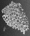
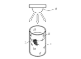
- the form of the molded body 10 in which the holes 13 are densely arranged with regularity is, for example, an image taken with a digital camera as shown in FIG. 6 and an image taken with an optical microscope as shown in FIG.
- FIG. 6 is an image taken from the outside of the container with the molded body 10 obtained by the method described later immersed in water in the container. There is a white lid at the top of the container, and FIG. 6 shows an image taken in a state where the container is supported by pinching this lid with a human finger.
- FIG. 7: is the image which image
- the image of FIG. 8 is an image which preserve
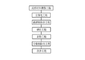
- the molded body 10 is manufactured including a molding material preparation step, a three-dimensionalization step, a continuous phase removal step, a curing step, a peeling step, a dispersed phase removal step, and a washing step. Manufactured by the method.
- the molded body 10 is manufactured from the molding material 20 (see FIG. 12), and the molding material adjustment step is a step of manufacturing the molding material 20.
- the molding material 20 is an emulsion (emulsion, emulsion), and as shown in FIG. 10, the droplets that are the dispersed phase 21 are the oil phase, and the continuous phase 22 is the water phase.
- the raw material of the material which comprises the molded object 10 is contained in the continuous phase 22 as a hardenable compound.
- the curable compound of this example becomes a hydrophilic material after curing.
- the curable compound in this example is acrylamide.
- the continuous phase 22 may contain a solvent of a curable compound.
- the droplets, which are the dispersed phase 21, function as a template (template) for the pores 13 in the molded body 10, and in this example, contain polydimethylsiloxane.
- the continuous phase 22 contains a curable compound as described above.
- the continuous phase 22 contains a curable compound and water as a solvent for the curable compound, but the curable compound is a liquid incompatible with the dispersed phase 21 which is a hydrophobic liquid.
- the continuous phase 22 may not contain water.
- being incompatible with the hydrophobic liquid means that the solubility in the hydrophobic liquid is 0.01 g / ml or less.
- Examples of the curable compound in the case where the continuous phase 22 is an aqueous phase include compounds in which a curable functional group is modified to a hydrophilic monomer, and a handbook of organic synthesis (for example, an organic synthesis experimental method handbook And the like), etc., it can be obtained by modifying a functional group having energy ray-curable (including photo-curable) and / or thermosetting.
- the curable compound is a UV curable compound which is cured by irradiation of ultraviolet rays in this example, but is not limited thereto.
- an energy ray curable compound which is cured by irradiation of energy rays a thermosetting compound which is cured by heating, and an ion curable compound which is cured by ion reaction can be used.
- An example of an energy ray curable compound which is cured by irradiation of energy rays is a photocurable compound which is cured by irradiation of light such as ultraviolet light.
- an ion-hardenable compound the system etc. which make sodium alginate react with polyvalent cations, such as a calcium (Ca) ion, are mentioned.
- the curable compound is preferably biocompatible.
- biocompatibility means the property which does not have a harmful
- the molding material 20 may contain a crosslinking agent for curing the curable compound in the continuous phase 22, and also in this example, N, N'-methylenebisacrylamide (manufactured by Tokyo Chemical Industry Co., Ltd.) is used as the crosslinking agent.
- the continuous phase 22 may contain an initiator for initiating curing of the curable compound, and also in this example, IRUGACURE (registered trademark) 2959 (manufactured by BASF SE) is included as an initiator. .
- the droplets of the dispersed phase 21 are preferably flexible and deformable, which is the case in this example.
- the diameter of the droplet that is the dispersed phase 21 is preferably in the range of 20 ⁇ m or more and 1 mm or less. By being 20 micrometers or more, compared with the case where it is less than 20 micrometers, union of droplets does not occur easily, and it is held more certainly as dispersed phase 51 of a flexible droplet. By being 1 mm or less, compared with the case of being larger than 1 mm, the shape of the droplet can be more reliably kept spherical as it is in the standing state.
- the diameter of the dispersed phase 51 is more preferably in the range of 0.1 mm or more and 1 mm or less, and still more preferably in the range of 0.2 mm or more and 0.6 mm or less.
- the specific gravity difference determined by Y1-Y2 is preferably 0.001 or more, and is set to 0.080 in this example.
- the specific gravity difference is 0.001 or more, the dispersed phase 21 can be easily unevenly distributed in the vertical direction, that is, downward distributed in the molding material 20, as compared to the case of less than 0.001.
- the molding material 20 is held in a state in which the dispersed phases 21 are in contact with each other more reliably in the three-dimensional process. can do. Further, in the case of producing the molded body 10, the floating of the dispersed phase 21 can be suppressed in the three-dimensional forming step and the curing step, so that the molded body 10 can be easily produced.
- the specific gravity difference is more preferably in the range of 0.001 or more and 0.200 or less. By being 0.200 or less, as compared with the case of exceeding 0.200, coalescence of the dispersed phases 21 which are droplets can be suppressed more reliably and / or longer. For example, when the difference in specific gravity is too large, the dispersed phase 21 in the state of being localized downward (sedimentation state) may be crushed and the stable state as a droplet may be disturbed.
- the specific gravity difference is more preferably in the range of 0.030 or more and 0.150 or less, and particularly preferably in the range of 0.050 or more and 0.100 or less.
- the specific gravity Y1 and the specific gravity Y2 are determined on the basis of the specific gravity of water at 25 ° C. being 1.
- the specific gravity of the first liquid 35 described later is Y1
- the specific gravity of the second liquid 36 described later is Y2
- the specific gravity of the first liquid 35 is 25% of volume V at 25 ° C.
- the first liquid 35 and the second liquid 36 are prepared, respectively, and the mass W of each of the prepared first liquid 35 and the second liquid 36 is measured 10 times, and the measured value is calculated by the equation of W / V. And the average value of ten calculated values is calculated
- the volume ratio of the dispersed phase 21 is in the range of 0.5 or more and 0.9 or less, and the dispersed phase 21 is contained in such a high volume ratio.
- the volume ratio of the dispersed phase 21 is determined by X1 / (X1 + X2), where X1 is the volume of the dispersed phase 21 and X2 is the volume of the continuous phase 22. Since the volume ratio of the dispersed phase 21 is 0.5 or more, the droplets of the dispersed phase 21 are arranged in contact with each other as compared with the case of less than 0.5, and the arrangement is more regularly Become.
- the volume ratio of the dispersed phase 21 is 0.9 or less, the unification of the dispersed phases 21 can be suppressed more reliably than in the case where the volume ratio exceeds 0.9. Therefore, it is easier to manufacture a molded body 10 in which the holes 13 of uniform size are regularly arranged.
- the volume ratio of the dispersed phase 21 is more preferably 0.6 or more and 0.85 or less, and still more preferably 0.7 or more and 0.8 or less.
- a method of obtaining the volume ratio of the dispersed phase 21 for example, there is a method of obtaining it from an image observed with a microscope. Specifically, the average size and the number density of droplets of the dispersed phase 21 can be obtained from the observation image of the molding material 20, and the volume ratio of the dispersed phase 21 can be calculated from the average size and the number density.
- the volume ratio of the dispersed phase 21 of the molding material 20 is the same as the volume ratio of the holes 13 of the obtained molded body 10
- the average size and the number of the holes 13 can be determined from the observation image of the molded body 10. This may be regarded as the volume ratio of the dispersed phase 21 in the molding material 20 by determining the density and the volume ratio of the holes 13 from these.
- the molding material 20 may contain a surfactant, and in this example also contains polyvinyl alcohol as a surfactant.
- a surfactant such as Adekatol (registered trademark) LA, NIKKOL Hexaglyn 1-M (hexaglyceryl monomyristate) and the like.
- the molding material 20 preferably contains a specific gravity regulator.
- a compound for increasing the specific gravity of the dispersed phase 21 is used as a specific gravity adjusting agent, but the specific gravity adjusting agent adjusts (increases or decreases) the specific gravity of at least one of the dispersed phase 21 and the continuous phase 22 If it is In this example, in order to increase the specific gravity of the dispersed phase 21, bromobenzene having a larger specific gravity than polydimethylsiloxane is used as a specific gravity regulator.
- the specific gravity adjusting agent for increasing the specific gravity of the dispersed phase 21 is not limited to this, and exists in a dissolved state in the dispersed phase 21 and the components of the dispersed phase 21 Any compound having a specific gravity larger than that of (in this example, polydimethylsiloxane) may be used.
- Any compound having a specific gravity larger than that of in this example, polydimethylsiloxane may be used.
- chloroform and / or carbon tetrachloride can be used.
- the specific gravity adjusting agent is preferably contained in the dispersed phase 21 as in this example.
- the specific gravity adjusting agent be contained at a mass ratio within the range of 1% to 30% with respect to the dispersed phase 21. This mass ratio is (M2 / M1) ⁇ when the mass of the dispersed phase 21 (including the mass of the specific gravity adjusting agent) is M1 and the mass of the specific gravity adjusting agent contained in the dispersed phase 21 is M2. It is a percentage determined by 100.
- the molding material 20 can be formed by the base producing unit 25 shown in FIG. 10 and the adjusting unit 26 shown in FIG.
- the base producing unit 25 produces an emulsion base 37 (see FIG. 11) in which the volume ratio of the dispersed phase 21 is smaller than that of the molding material 20.
- the base agent generation unit 25 includes a first pipe 31 and a second pipe 32 which are circular in cross section.
- the first pipe 31 supplies the first liquid 35 to be the dispersed phase 21.
- the second pipe 32 delivers the second liquid 36 to be the continuous phase 22.
- the first pipe 31 is fitted to the side surface of the second pipe 32 in a state in which one end side is disposed in the hollow portion of the second pipe 32.
- the opening 31a at one end side of the first pipe 31 is disposed in a direction facing the flow direction of the second liquid 36 (downstream in the flow direction of the second liquid 32) flowing in one direction through the hollow portion of the second pipe 32 ing. Thereby, the first liquid 35 is discharged as a droplet from the opening 31 a in the flow direction of the second liquid 36. Further, the opening 31 a is located approximately at the center of the circular cross section of the second pipe 32.
- the first pipe 31 whose outer diameter is in the range of 0.8 mm to 3.0 mm and the inner diameter are larger than the outer diameter of the first pipe 31 and the outer diameter is approximately 1.
- the 2nd pipe 32 which is in the range of 4 mm or more and 4.0 mm or less is used.
- the first pipe 31 and the second pipe 32 are not limited to this example.
- the flow rate of the first liquid 35 is V1 and the flow rate of the second liquid 36 is V2, for example, V1 is 3 ml / hr and V2 is 4.5 ml / hr.
- V1 is 3 ml / hr
- V2 is 4.5 ml / hr.
- the specific gravity adjusting agent is contained in the first liquid 35.
- the dispersed phase 21 containing a specific gravity regulator is produced.
- the crosslinking agent, the initiator and the surfactant are contained in the second liquid 36.
- a continuous phase 22 containing a crosslinking agent and an initiator is formed, and the droplets of the dispersed phase 21 are held in a stable state in the continuous phase 22.
- the obtained emulsion base 37 is sent to the container 38 of the adjustment unit 26 shown in FIG.
- the adjustment unit 26 includes a container 38 for containing the emulsion base 37 and a pump 39.
- the pump 39 sucks the second liquid 36 from the emulsion base 37 in the container 38, thereby increasing the volume ratio of the dispersed phase 21 in the emulsion base 37. Thereby, the molding material 20 is obtained.
- the three-dimensionalizing step is a step of housing the molding material 20 in a container 41 having a size including the entire molded body 10 as shown in FIG.
- a container 41 having an inner wall which is the outer shape (shape and size) of the molded body 10 is used, and the container 41 is made of glass through which light from the light source 40 is transmitted. Since the molded body 10 after curing is formed of a hydrophilic material, the container 41 made of a hydrophobic material may be used in terms of the ease of separation of the container 41 and the molded body 10.
- the dispersed phases 21 When the dispersed phases 21 are in contact with each other at the time of storage, they may be immediately subjected to the curing step.
- processing such as standing still or gently vibrating and / or oscillating until they are in contact with each other It is recommended to perform the curing step after
- the continuous layer removing step after the dispersed phases 21 come into contact with each other, when the arrangement of the dispersed phases 21 is substantially absent at the top of the vessel 41, that is, when only the substantially continuous phase 22 is present This is a step of removing the phase 22.
- a pump 39 can be used to remove the continuous phase 22.
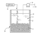
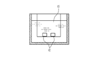
- the curing step after the continuous layer removing step is a step of curing the curable compound contained in the continuous phase 22 of the molding material 20, as shown in FIG. Since acrylamide which is a curable compound of this example is a photocurable compound, for example, as shown in FIG. 12, a light source 40 is used in the curing step.
- the container 41 is placed under the light source 40 described above, and the curable compound in the molding material 20 is cured.
- the position relationship between the light source 40 and the container 41 is not particularly limited, as long as the molding material 20 needs to be irradiated with light.
- a plurality of light sources 40 may be disposed around the container 41, and light may be emitted toward the container 41 from different directions.
- the light source 40 is disposed above the glass container 41 containing the molding material 20. In this state, by emitting light for curing the curable compound from the light source 40, the light is irradiated to the molding material 20 through the transparent container 41, and the curing compound is cured by this irradiation, and the molding material 20 is It becomes a solidified body 42 in which the continuous phase is solidified.
- the light source 40 of this example emits ultraviolet light as light.
- the curing device for the curing process is not limited to the light source 40 but is determined according to the curing method.
- the curable compound is a thermosetting compound that cures by heating
- various heating devices such as a heating oven (heating thermostat) or an infrared heater are used in the curing step.
- a heating oven heating thermostat
- an infrared heater are used in the curing step.
- a liquid tank containing an ion solution is used as a curing device.
- the ion solution (for example, a solution containing calcium ions) of this liquid tank is little by little so as not to disturb the arrangement of the dispersed phase 21 of the molding material 20 in the container 41 containing the molding material 20
- the injection cures the ion curable compound (eg, sodium alginate).
- the peeling step is a step of separating the solidified body 42 obtained by the curing from the container 41.
- the separation may be performed by any method, and may be performed by heat or may be physically performed by peeling.
- the containers 41 can be alternately immersed in cold water and hot water.
- the solidified body 42 is stripped from the container 41 by immersing the container 41 containing the solidified body 42 in the water of a bath containing water at 25 ° C.
- the container 41 in which the solidified body 42 is accommodated may be alternately and repeatedly immersed in different first baths (not shown) and second baths (not shown) which are different from each other. In this case, the temperature difference between the first and second baths may be sufficient.
- the dispersed phase removing step is a step of removing the dispersed phase 21 from the solidified body 42 obtained by the stripping step as shown in FIG.
- the liquid 45 exhibits solubility in the dispersed phase 21 in the solidified body 42, and is insoluble in the continuous phase (product generated by curing of the curable compound) in the solidified body 42, By immersing the solidified body 42, the dispersed phase 21 is removed from the solidified body 42.
- the liquid used in this example is acetone, but is not limited to acetone.
- the insolubility with respect to the continuous phase in the solidified body 42 is not limited to the meaning that it does not melt
- the solvent of the curable compound remains in the continuous phase as described above, the product of the product formed by the curing of the curable compound, even if the solubility of the continuous phase is greater than 0.01 g / ml. If the solubility is 0.01 g / ml or less, it may be regarded as insoluble.
- the dispersed phase 21 Since the dispersed phase 21 is in contact with each other in the solidified body 42, the dispersed phase 21 is easily removed, and the dispersed phase 21 is also removed by a method other than drying such as immersion in the present example. Therefore, there is freedom in selecting the material used as the dispersed phase 21. As described above, since the degree of freedom of the material used as the dispersed phase 21 is high, the degree of freedom in selecting the material of the continuous phase 22 used together with the dispersed phase 21 is high, and as a result, molded bodies 10 of various materials can be obtained.
- the washing step after the dispersed phase removing step, the green body 10 is washed by immersing the green body 10 in water and / or a solvent.
- cleaning process it is preferable to perform a washing
- the molded body 10 is obtained from the molding material 20 as described above.
- the molding material 20 includes the dispersed phase 21 and the continuous phase 22, and the droplets as the deformable dispersed phase 21 function as a mold (template) of the pores in the molded body 10. Since the dispersed phase 21 is contained at the above-mentioned volume ratio, the droplets which are the dispersed phase 21 are arranged in contact with each other, and the arrangement becomes more regular. Further, since the dispersed phases 21 are arranged in contact with each other, the dispersed phase is easily removed in the dispersed phase removing step, and as a result, a compact 10 in which the holes 13 communicate with each other can be obtained.
- the continuous phase 22 and the dispersed phase 21 are separated from each other, and the dispersed phase 21 is flexible and deformable, it is possible to use the molding material 20 as a mold at the time of producing the molded body 10 by gravity.
- the dispersion phase 21 is arranged in a three-dimensional close-packed structure in a self-organizing manner only by charging. Even when a molding material having a relatively small difference in specific gravity between the continuous phase 22 and the dispersed phase 21 is used, the dispersed phase 21 is three-dimensionally self-organized by placing the molding material 20 in a container and leaving it to stand. Arrange in a close-packed structure.
- the dispersed phase 21 contained in the dense state in the three-dimensional forming process can form a regular array more reliably, and a gap is formed below by gravity. If you move there. Therefore, the molded body 10 is disposed in a state in which the dispersed phase 21 is distributed in an arrangement with more regularity and the dispersed phases 21 are in contact with each other more reliably. Also, the dispersed phase 22 can be rearranged even if it takes a certain sequence with high regularity in a self-organizing manner. Moreover, since the shape of the porous molded body conforms to the shape of the container, porous molded bodies of various shapes can be easily obtained.
- the molded body 10 has a void 12 opened to the surface, and the void 12 is formed by communication between a plurality of spherical void portions 13 arranged in a close-packed structure. Further, the molded body 10 is a molded body 10 made of a hydrophilic material and in which the cavity portions 13 of which the dispersed phase 21 is a mold are densely arranged with regularity regardless of the surface or the inside, regardless of the surface. is there. Note that "any part” does not mean strictness, and it is highly ordered with regularity in most parts of the molded body 10, and part of the corners and edges etc. It means that there may be a disturbed part.
- the dispersed phase 21 has a close packed structure along the container 10 and is highly regularly arranged along the container 10 by the step of removing the continuous phase 22, etc. Thirteen surface openings 12a are also highly regularly arranged in a close-packed configuration. Similarly, also in the inside of the molded body 10, the dispersed phase 21 takes a close packed structure and is highly regularly arranged, so the holes 13 are also arranged regularly in a closely packed structure.
- the surface of the molded body also has a curved surface similar to that of the container. For example, like a hollow of a golf ball, the opening is highly ordered along the curved surface. It is possible to obtain shaped bodies arranged in an array.
- the pores having uniform sizes are arranged in a highly regular manner in a close-packed structure, they communicate with each other and are opened on the surface, and the openings are also arranged regularly. It is suitable for applications in which it is preferable to have uniform pores, applications in which the pores are preferably filled with a substance or the like densely, and applications in which a large surface area is preferable. Moreover, if it is the same raw material, since it can be set as a lightweight molded object, it is suitable also for the use to which light is preferable.
- a porous formed body having a diameter in a wide range of 1 ⁇ m to 1 mm or less or a formed body having a porous surface can be easily obtained. Therefore, the size distribution of the pores is small, and moreover, the size of the pores can be made specific, and a molded article adjusted to a specific porosity can be easily obtained, so applications such as sieves and filters Is also suitable.
- the close-packed structure is a hexagonal close-packed structure and / or a cubic close-packed structure, and the pores 13 are compacted bodies 10 closely arranged with regularity along the packing structure, the pores It is suitable for the application where it is preferable that 13 arranges regularly.
- gap 12 with respect to the whole porous molded object can be as high as 74% or more, it is suitable for the use with preferable that the space
- the center-to-center distance D2 of the hole 13 in contact is smaller than the diameter D1 of the hole 13, the holes 13 communicate with each other more reliably. For this reason, it is suitable for the use for which it is preferable that the space
- the size distribution of the plurality of spherical holes 13 is as small as 5% or less, it is preferable that the sizes of the holes 13 be uniform and the sizes of the holes 13 be uniform. It is suitable.
- the hydrophilic material has biocompatibility, it is suitable when the molded body 10 is used in a biorelated application.
- the hydrophilic material is selected from collagen, polyglycolic acid, chitosan and hydroxyapatite, and collagen, polyglycolic acid, chitosan and derivatives or mixtures of hydroxyapatite, for example, the molded body 10 is used for the human body Suitable for use.
- the hydrophilic material is biodegradable, the load on the environment is small, which is preferable.
- a larger communication port 12 b is formed in the obtained molded body 10.
- the formation of a larger communication port 12b in this way is effective, for example, in the case of using the molded body 10 as a cell culture substrate, by securing an interaction path between cultured cells.
- the molded body 50 of the second embodiment has a structure in which the holes 51 different from the holes 13 are regularly embedded in the gaps of the hexagonal close-packed structure of the holes 13. ing. Therefore, on the surface 50 a of the molded body 50, the openings 13 a of the hole 13 and the openings 51 a of the hole 51 are regularly arranged.
- the plurality of openings 13a have the same diameter, and the plurality of openings 51a have the same diameter.
- the hole 13 and the hole 51 communicate with each other at the contact portion.
- a void 52 formed of the void portion 13 and the void portion 51 penetrates the formed body 50.
- the molded body 50 is the same as that of the first embodiment except that two types of dispersed phases having different droplet diameters are used as the dispersed phase.
- Emulsion base material including dispersed phase 1 using dispersed phase hereinafter referred to as dispersed phase 1) having large droplet diameter and dispersed phase (hereinafter referred to as dispersed phase 2) having smaller droplet diameter than this
- dispersed phase 2 having smaller droplet diameter than this
- the emulsion base material containing the dispersed phase 2 are separately manufactured, and then both are mixed in the preparation unit 26.
- the other steps are the same as in the first embodiment.
- the dispersed phase having different droplet diameters As described above, it is possible to obtain a molded body having a higher porosity by using the dispersed phase having different droplet diameters. Therefore, it is suitable for applications in which it is preferable to closely fill a substance or the like with pores and applications in which it is preferable to have a larger surface area.
- the size of the cavity can be made plural in one molded body, and in some cases, the position thereof is also adjusted It is possible.
- one having a large droplet diameter of the dispersed phase is disposed at the bottom of the container, a dispersed phase having a slightly smaller droplet diameter than the one is disposed at the middle of the container, and a dispersed phase having a smaller droplet diameter is
- arranging at the upper part of the container it is possible to obtain a porous formed body in which the arrangement of the holes is changed stepwise. Therefore, in the same molded body, it is suitable for applications in which it is preferable to give another function to each partial region.
- the continuous phase and the dispersed phase it is possible to easily obtain a compact having a controlled pore.
- a part of the surface 60 a of the molded body 60 is a curved surface.
- one layer of the hole 61 forming the surface 60a is illustrated, and the others are omitted.
- the diameter D3 of the opening 62 is substantially the same.
- the molded body 60 is manufactured in the same manner as in the first embodiment except that a container having a curved surface is used. Since the dispersed phase 21 is deformable and the dispersed phase is arrayed following the curved surface, as shown in FIG. 15, the obtained molded product 60 has the diameter D3 of the opening 62 even on the curved surface. In all the openings 62 that open to the
- the openings having approximately the same diameter regularly arranged on the surface can provide a surface shape suitable for applications such as cell culture substrates and sieves.
Landscapes
- Chemical & Material Sciences (AREA)
- Engineering & Computer Science (AREA)
- Materials Engineering (AREA)
- Health & Medical Sciences (AREA)
- Chemical Kinetics & Catalysis (AREA)
- Medicinal Chemistry (AREA)
- Polymers & Plastics (AREA)
- Organic Chemistry (AREA)
- Manufacture Of Porous Articles, And Recovery And Treatment Of Waste Products (AREA)
Abstract
La présente invention concerne un article poreux moulé fabriqué à partir d'un matériau hydrophile dans lequel les trous sont disposés densément d'une manière régulière dans toutes les parties. Un article poreux moulé (10) présente des vides dans l'intérieur, et une pluralité d'ouvertures (12a) sont formées sur la surface (10S). Les ouvertures (12a) de l'article poreux moulé (10) sont telles que les vides sont exposés sur la surface (10S). L'article poreux moulé (10) présente des vides ouverts sur la surface (10S). Une pluralité de trous sphériques sont reliés dans l'intérieur de l'article moulé (10), et ces trous forment des vides.
Priority Applications (1)
| Application Number | Priority Date | Filing Date | Title |
|---|---|---|---|
| JP2019567064A JP7113034B2 (ja) | 2018-01-23 | 2019-01-21 | 多孔成形体 |
Applications Claiming Priority (2)
| Application Number | Priority Date | Filing Date | Title |
|---|---|---|---|
| JP2018-008559 | 2018-01-23 | ||
| JP2018008559 | 2018-01-23 |
Publications (1)
| Publication Number | Publication Date |
|---|---|
| WO2019146558A1 true WO2019146558A1 (fr) | 2019-08-01 |
Family
ID=67395673
Family Applications (1)
| Application Number | Title | Priority Date | Filing Date |
|---|---|---|---|
| PCT/JP2019/001728 Ceased WO2019146558A1 (fr) | 2018-01-23 | 2019-01-21 | Article poreux moulé |
Country Status (3)
| Country | Link |
|---|---|
| JP (1) | JP7113034B2 (fr) |
| TW (1) | TW201936217A (fr) |
| WO (1) | WO2019146558A1 (fr) |
Citations (8)
| Publication number | Priority date | Publication date | Assignee | Title |
|---|---|---|---|---|
| JPS5661437A (en) * | 1979-10-23 | 1981-05-26 | Sadao Hayashi | Porous synthetic membrane and production thereof |
| JP2003511521A (ja) * | 1999-10-12 | 2003-03-25 | 株式会社日本触媒 | 多孔質架橋重合体の製造方法 |
| JP2007510183A (ja) * | 2003-10-31 | 2007-04-19 | コーニング インコーポレイテッド | 大型コロイド結晶およびマクロポーラス・ポリマー並びにそれらの製造方法 |
| JP2009268836A (ja) * | 2008-05-09 | 2009-11-19 | Kinki Univ | 逆オパール構造体、その製造方法及び使用方法 |
| WO2010058148A1 (fr) * | 2008-10-08 | 2010-05-27 | Imperial Innovations Ltd | Émulsions stabilisées par des particules organiques rendues hydrophobes |
| JP2012509960A (ja) * | 2008-11-24 | 2012-04-26 | コーニング インコーポレイテッド | 3d細胞培養物品およびその方法 |
| JP2013504669A (ja) * | 2009-09-16 | 2013-02-07 | スフィリテック・リミテッド | 三次元多孔質構造体 |
| WO2017104610A1 (fr) * | 2015-12-14 | 2017-06-22 | 国立研究開発法人科学技術振興機構 | Film poreux, procédé de fabrication de film poreux, réseau de microlentilles, microréacteur et dispositif biologique |
-
2019
- 2019-01-21 JP JP2019567064A patent/JP7113034B2/ja active Active
- 2019-01-21 WO PCT/JP2019/001728 patent/WO2019146558A1/fr not_active Ceased
- 2019-01-23 TW TW108102577A patent/TW201936217A/zh unknown
Patent Citations (8)
| Publication number | Priority date | Publication date | Assignee | Title |
|---|---|---|---|---|
| JPS5661437A (en) * | 1979-10-23 | 1981-05-26 | Sadao Hayashi | Porous synthetic membrane and production thereof |
| JP2003511521A (ja) * | 1999-10-12 | 2003-03-25 | 株式会社日本触媒 | 多孔質架橋重合体の製造方法 |
| JP2007510183A (ja) * | 2003-10-31 | 2007-04-19 | コーニング インコーポレイテッド | 大型コロイド結晶およびマクロポーラス・ポリマー並びにそれらの製造方法 |
| JP2009268836A (ja) * | 2008-05-09 | 2009-11-19 | Kinki Univ | 逆オパール構造体、その製造方法及び使用方法 |
| WO2010058148A1 (fr) * | 2008-10-08 | 2010-05-27 | Imperial Innovations Ltd | Émulsions stabilisées par des particules organiques rendues hydrophobes |
| JP2012509960A (ja) * | 2008-11-24 | 2012-04-26 | コーニング インコーポレイテッド | 3d細胞培養物品およびその方法 |
| JP2013504669A (ja) * | 2009-09-16 | 2013-02-07 | スフィリテック・リミテッド | 三次元多孔質構造体 |
| WO2017104610A1 (fr) * | 2015-12-14 | 2017-06-22 | 国立研究開発法人科学技術振興機構 | Film poreux, procédé de fabrication de film poreux, réseau de microlentilles, microréacteur et dispositif biologique |
Also Published As
| Publication number | Publication date |
|---|---|
| JPWO2019146558A1 (ja) | 2021-01-07 |
| TW201936217A (zh) | 2019-09-16 |
| JP7113034B2 (ja) | 2022-08-04 |
Similar Documents
| Publication | Publication Date | Title |
|---|---|---|
| Hinton et al. | 3D printing PDMS elastomer in a hydrophilic support bath via freeform reversible embedding | |
| CN110770028B (zh) | 用于在立体光刻系统中使用的容器 | |
| RU2377125C1 (ru) | Миниатюрная матричная структура ячеек и способ получения миниатюризованной детали из композиционного материала с применением миниатюрной матричной структуры ячеек | |
| CA2838018C (fr) | Procede de fabrication de dispositifs microfluidiques monolithiques tridimensionnels | |
| Lölsberg et al. | Two‐Photon Vertical‐Flow Lithography for Microtube Synthesis | |
| Yasuga et al. | Fluid interfacial energy drives the emergence of three-dimensional periodic structures in micropillar scaffolds | |
| Nguyen et al. | Porous structures prepared by a novel route: Combination of digital light processing 3D printing and leaching method | |
| Zhao et al. | Microfluidic technology for the production of well-ordered porous polymer scaffolds | |
| JP6966575B2 (ja) | 多孔成形体の製造方法 | |
| Choi et al. | Microfluidic synthesis of anisotropic particles from Janus drop by in situ photopolymerization | |
| Chen et al. | Acoustics in additive manufacturing: A path toward contactless, scalable, and high-precision manufacturing | |
| WO2019146558A1 (fr) | Article poreux moulé | |
| JPWO2019146557A1 (ja) | 成形材料 | |
| JP6966574B2 (ja) | 多孔質成形体の製造方法 | |
| US12215203B2 (en) | Method for producing microparticles | |
| US12384076B2 (en) | Method for fabricating microparticle by using degassed gas-permeable micromold and discontinuous dewetting | |
| Leng | Flow-Based Organization of Perfusable Soft Material in Three Dimensions | |
| Barry III | Functional microperiodic polyacrylamide gels fabricated by opal inversion and direct-write processes |
Legal Events
| Date | Code | Title | Description |
|---|---|---|---|
| 121 | Ep: the epo has been informed by wipo that ep was designated in this application |
Ref document number: 19743113 Country of ref document: EP Kind code of ref document: A1 |
|
| ENP | Entry into the national phase |
Ref document number: 2019567064 Country of ref document: JP Kind code of ref document: A |
|
| NENP | Non-entry into the national phase |
Ref country code: DE |
|
| 122 | Ep: pct application non-entry in european phase |
Ref document number: 19743113 Country of ref document: EP Kind code of ref document: A1 |