WO2019146708A1 - Élément de fixation - Google Patents
Élément de fixation Download PDFInfo
- Publication number
- WO2019146708A1 WO2019146708A1 PCT/JP2019/002307 JP2019002307W WO2019146708A1 WO 2019146708 A1 WO2019146708 A1 WO 2019146708A1 JP 2019002307 W JP2019002307 W JP 2019002307W WO 2019146708 A1 WO2019146708 A1 WO 2019146708A1
- Authority
- WO
- WIPO (PCT)
- Prior art keywords
- lid
- box
- fastener
- knob
- receiving
- Prior art date
- Legal status (The legal status is an assumption and is not a legal conclusion. Google has not performed a legal analysis and makes no representation as to the accuracy of the status listed.)
- Ceased
Links
Images





Classifications
-
- B—PERFORMING OPERATIONS; TRANSPORTING
- B26—HAND CUTTING TOOLS; CUTTING; SEVERING
- B26B—HAND-HELD CUTTING TOOLS NOT OTHERWISE PROVIDED FOR
- B26B3/00—Hand knives with fixed blades
- B26B3/08—Hand knives with fixed blades specially adapted for cutting cardboard, or wall, floor, or like covering materials
-
- B—PERFORMING OPERATIONS; TRANSPORTING
- B65—CONVEYING; PACKING; STORING; HANDLING THIN OR FILAMENTARY MATERIAL
- B65D—CONTAINERS FOR STORAGE OR TRANSPORT OF ARTICLES OR MATERIALS, e.g. BAGS, BARRELS, BOTTLES, BOXES, CANS, CARTONS, CRATES, DRUMS, JARS, TANKS, HOPPERS, FORWARDING CONTAINERS; ACCESSORIES, CLOSURES, OR FITTINGS THEREFOR; PACKAGING ELEMENTS; PACKAGES
- B65D5/00—Rigid or semi-rigid containers of polygonal cross-section, e.g. boxes, cartons or trays, formed by folding or erecting one or more blanks made of paper
- B65D5/42—Details of containers or of foldable or erectable container blanks
- B65D5/64—Lids
- B65D5/66—Hinged lids
- B65D5/6602—Hinged lids formed by folding one or more extensions hinged to the upper edge of a tubular container body
- B65D5/6611—Hinged lids formed by folding one or more extensions hinged to the upper edge of a tubular container body the lid being held in closed position by application of separate elements, e.g. clips, hooks, elastics
-
- B—PERFORMING OPERATIONS; TRANSPORTING
- B65—CONVEYING; PACKING; STORING; HANDLING THIN OR FILAMENTARY MATERIAL
- B65D—CONTAINERS FOR STORAGE OR TRANSPORT OF ARTICLES OR MATERIALS, e.g. BAGS, BARRELS, BOTTLES, BOXES, CANS, CARTONS, CRATES, DRUMS, JARS, TANKS, HOPPERS, FORWARDING CONTAINERS; ACCESSORIES, CLOSURES, OR FITTINGS THEREFOR; PACKAGING ELEMENTS; PACKAGES
- B65D5/00—Rigid or semi-rigid containers of polygonal cross-section, e.g. boxes, cartons or trays, formed by folding or erecting one or more blanks made of paper
- B65D5/42—Details of containers or of foldable or erectable container blanks
- B65D5/64—Lids
- B65D5/643—Lids held in closed position by application of separate elements, e.g. clips, straps
-
- B—PERFORMING OPERATIONS; TRANSPORTING
- B65—CONVEYING; PACKING; STORING; HANDLING THIN OR FILAMENTARY MATERIAL
- B65D—CONTAINERS FOR STORAGE OR TRANSPORT OF ARTICLES OR MATERIALS, e.g. BAGS, BARRELS, BOTTLES, BOXES, CANS, CARTONS, CRATES, DRUMS, JARS, TANKS, HOPPERS, FORWARDING CONTAINERS; ACCESSORIES, CLOSURES, OR FITTINGS THEREFOR; PACKAGING ELEMENTS; PACKAGES
- B65D5/00—Rigid or semi-rigid containers of polygonal cross-section, e.g. boxes, cartons or trays, formed by folding or erecting one or more blanks made of paper
- B65D5/42—Details of containers or of foldable or erectable container blanks
- B65D5/64—Lids
- B65D5/66—Hinged lids
- B65D5/6602—Hinged lids formed by folding one or more extensions hinged to the upper edge of a tubular container body
- B65D5/6605—Hinged lids formed by folding one or more extensions hinged to the upper edge of a tubular container body the lid being formed by two mating halves joined to opposite edges of the container body
-
- B—PERFORMING OPERATIONS; TRANSPORTING
- B65—CONVEYING; PACKING; STORING; HANDLING THIN OR FILAMENTARY MATERIAL
- B65D—CONTAINERS FOR STORAGE OR TRANSPORT OF ARTICLES OR MATERIALS, e.g. BAGS, BARRELS, BOTTLES, BOXES, CANS, CARTONS, CRATES, DRUMS, JARS, TANKS, HOPPERS, FORWARDING CONTAINERS; ACCESSORIES, CLOSURES, OR FITTINGS THEREFOR; PACKAGING ELEMENTS; PACKAGES
- B65D5/00—Rigid or semi-rigid containers of polygonal cross-section, e.g. boxes, cartons or trays, formed by folding or erecting one or more blanks made of paper
- B65D5/42—Details of containers or of foldable or erectable container blanks
- B65D5/64—Lids
- B65D5/66—Hinged lids
- B65D5/6626—Hinged lids formed by folding extensions of a side panel of a container body formed by erecting a "cross-like" blank
- B65D5/6629—Hinged lids formed by folding extensions of a side panel of a container body formed by erecting a "cross-like" blank the lid being formed by two mating halves joined to opposite edges of the container body
- B65D5/6647—Hinged lids formed by folding extensions of a side panel of a container body formed by erecting a "cross-like" blank the lid being formed by two mating halves joined to opposite edges of the container body the lid-halves being held in closed position by application of separate elements, e.g. clips, hooks, cords
-
- F—MECHANICAL ENGINEERING; LIGHTING; HEATING; WEAPONS; BLASTING
- F16—ENGINEERING ELEMENTS AND UNITS; GENERAL MEASURES FOR PRODUCING AND MAINTAINING EFFECTIVE FUNCTIONING OF MACHINES OR INSTALLATIONS; THERMAL INSULATION IN GENERAL
- F16B—DEVICES FOR FASTENING OR SECURING CONSTRUCTIONAL ELEMENTS OR MACHINE PARTS TOGETHER, e.g. NAILS, BOLTS, CIRCLIPS, CLAMPS, CLIPS OR WEDGES; JOINTS OR JOINTING
- F16B5/00—Joining sheets or plates, e.g. panels, to one another or to strips or bars parallel to them
- F16B5/06—Joining sheets or plates, e.g. panels, to one another or to strips or bars parallel to them by means of clamps or clips
- F16B5/0607—Joining sheets or plates, e.g. panels, to one another or to strips or bars parallel to them by means of clamps or clips joining sheets or plates to each other
- F16B5/0621—Joining sheets or plates, e.g. panels, to one another or to strips or bars parallel to them by means of clamps or clips joining sheets or plates to each other in parallel relationship
- F16B5/0635—Joining sheets or plates, e.g. panels, to one another or to strips or bars parallel to them by means of clamps or clips joining sheets or plates to each other in parallel relationship fastened over the edges of the sheets or plates
-
- B—PERFORMING OPERATIONS; TRANSPORTING
- B65—CONVEYING; PACKING; STORING; HANDLING THIN OR FILAMENTARY MATERIAL
- B65D—CONTAINERS FOR STORAGE OR TRANSPORT OF ARTICLES OR MATERIALS, e.g. BAGS, BARRELS, BOTTLES, BOXES, CANS, CARTONS, CRATES, DRUMS, JARS, TANKS, HOPPERS, FORWARDING CONTAINERS; ACCESSORIES, CLOSURES, OR FITTINGS THEREFOR; PACKAGING ELEMENTS; PACKAGES
- B65D5/00—Rigid or semi-rigid containers of polygonal cross-section, e.g. boxes, cartons or trays, formed by folding or erecting one or more blanks made of paper
- B65D5/42—Details of containers or of foldable or erectable container blanks
- B65D5/44—Integral, inserted or attached portions forming internal or external fittings
Definitions
- the present invention relates to a fastener for securing a double-sided lid of a box in a closed state.
- the fastener of Patent Document 1 has insertion portions provided back-to-back, and one of the double lids of the box is inserted in advance into one insertion portion, and the fastener is attached, while both lids are closed. The other lid is inserted into the other insertion portion to fix the lid.
- the fastener of patent document 2 is provided with a lower presser and an upper presser, and the lower presser is inserted in the joint of the lid in a state where the double-detached lid of the box is semi-closed, and the lid is closed. By holding and rotating, the fastener is locked to the lid to fix the lid.
- Patent Document 1 Japanese Patent Application Publication No. 2001-301753 JP, 2016-43968, A
- the present invention has been made in view of such circumstances, and is for fixing in a state in which a double-sided lid of a box is closed, and a fastener that can also be used for unpacking the box. Intended to be provided.
- the present invention is to fix in a state in which a double-opening lid of a box is closed, and includes a receiving portion, a pressing portion, and a connecting portion, and the receiving portion and the pressing portion face each other through the connecting portion.
- the space between the receiving part and the pressing part on both sides sandwiching the connecting part is an inserting part for inserting the lid of the box, and the receiving part, the pressing part or the connection.
- the unit is characterized in that a cutter unit is provided.
- the cutter part should just be sharp to such an extent that the tape which closed the lid of the box can be cut.
- the receiving portion extends left and right
- a lid contact portion that contacts the surface of the lid is provided on at least one of the front and rear sides
- the lid contact portion is at least
- a part is an upwardly bent or bendable knob
- the connecting part is a rod-like part, and extends downward from the center in the left-right direction of the receiving part
- the pressing part is closed. It may be a bar-like top view that can be inserted from the gap between the seams of both lids in a folded state, and may extend to the left and right from the lower end of the connecting portion.
- the knob is bendable or bendable upward
- the knob itself is made of a flexible material and is bendable
- the joint between the knob and the other part is a fold or a hinge and that part It includes various configurations capable of turning up the knob, such as flexible ones.
- the direction of front and rear, right and left up and down is shown, this is defined for convenience, in order to show the relationship between members, and does not limit the direction of use condition.
- the tip end portion of the knob portion may be a finger hook portion which is always separated from the lid in a state where the lower surface of the root portion is in contact with the lid.
- the root portion of the knob is a portion joined to the other portion, and the tip of the knob is a portion opposite to the root and is a portion which moves by bending or bending. .
- the present invention it is possible to fix the lid in a closed state by inserting the lids of the both sides of the box into the insertion portions on both sides of the connecting portion. And since the tape can be cut and the box can be unpacked by the cutter part provided in the receiving part, the pressing part or the connecting part, it is not necessary to use other tools from the unpacking work to the repacking work, which is convenient. Sex is high.
- the connecting portion is rod-shaped if the lid has a rod contacting portion at least a part of which is a picking portion and a rod-shaped pressing portion in a top view
- the pressing portion is a gap between the two open lids of the box.
- the lid is inserted into the insertion portion between the receiving portion and the pressing portion by inserting it into the housing, and the lid can be fixed in a closed state.
- the knob of the lid contact portion provided on the receiving portion Since the part is bendable or bendable upward, it is easy to pick it up with a finger by turning up the knob, and the fastener can be easily rotated.
- the tip end portion is a lid in a state where the lower surface of the root portion of the knob portion is in contact with the lid, that is, in a state where the pressing portion is inserted into the gap between the two lids of the box. Since it becomes a finger hook part separated from, it is possible to easily turn up the pick part by putting a finger on the finger hook part.
- FIG. 4 is a cross-sectional view taken along line IV-IV of FIG. 3; The case where the cutter part of 1st embodiment is used is shown, (a) is a general view, (b) is an enlarged view.
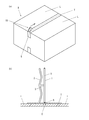
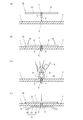
- (A) to (d) show the procedure for fixing the lid according to the first embodiment. It is a perspective view of the box fixed with the lid closed according to the first embodiment.
- FIG. 9 is a cross-sectional view taken along line IX-IX in FIG.
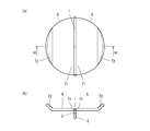
- the 3rd embodiment of a fastener is shown, (a) is a top view, (b) is a side view.
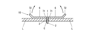
- 11 is a cross-sectional view taken along line XI-XI of FIG.
- the 4th embodiment of a fastener is shown, (a) is a top view, (b) is a side view.
- FIG. 13 is a cross-sectional view taken along line XIII-XIII of FIG.
- the 5th embodiment of a fastener is shown, (a) is a top view, (b) is a side view.
- FIG. 15 is a cross-sectional view taken along line XV-XV in FIG.
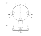
- the 6th embodiment of a fastener is shown, (a) is a top view, (b) is a side view.
- FIG. 17 is a cross-sectional view taken along line XVII-XVII in FIG.
- This fastener is intended to be fixed in a closed state with a lid in a closed state for a box provided with various double-ended lids, but here an example for a cardboard box is taken as an example.
- the left-right direction is the direction in which the receiving portion 1 described later extends
- the front-rear direction is the direction orthogonal to the left-right direction.
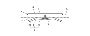
- the receiving portion 1, the pressing portion 2, the connecting portion 3, the inserting portion 4, the cutter portion 5 and the lid contacting portion (picking portion) 6 is provided in the first embodiment of the fastener.
- the receiving portion 1 is a bar-like member having a length of about 5 cm and a square cross section, and extends horizontally in the left-right direction. Further, on the lower surface at the center in the left-right direction of the receiving portion 1, there is formed a connecting portion 3 which is a bar-like member having a circular cross section and which extends downward. Furthermore, at the lower end of the connecting portion 3, there is formed a pressing portion 2 which is a bar-like member having a circular cross section and extending to both left and right sides, that is, the receiving portion 1 and the pressing portion 2 face each other via the connecting portion 3. There is.
- the pressing portion 2 has a left-right symmetrical shape with the connecting portion 3 as a central axis, extends obliquely upward from the lower end of the connecting portion 3, and bends halfway to extend obliquely downward.
- the bent portion is a bent point 21, and a portion extending inwardly and obliquely from the bent point 21 toward the outer peripheral side is directed obliquely downward toward the outer peripheral side and outward from the inner portion 22 and the bent point 21.
- An extending portion is referred to as an outer portion 23.
- the left and right lengths of the inner portion 22 and the outer portion 23 are substantially the same, and the left and right positions of the tip of the outer portion 23 are substantially the same as the left and right positions of the tip of the receiving portion 1.
- the insertion portion 4 is narrowest at the position of the bending point 21 of the pressing portion 2 and has a shape in which the width widens from the position of the bending point 21 toward the opening side and the back side.
- the receiving portion 1, the connecting portion 3 and the pressing portion 2 are made of hard resin and are integrally formed.
- lid L is the inner portion 22 It deforms and spreads the insertion part 4.
- the pressing portion 2 presses the lid L inserted into the insertion portion 4 against the receiving portion 1.
- the lid L is fixed in this state by being inserted into the insertion portions 4 on both the left and right sides in a state in which the double-sided lid L of the box is closed.
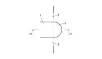
- cutters 5 are provided at both end portions of the receiving portion 1 in the left-right direction.
- the cutter portion 5 is semicircular in plan view, triangular in front view, and triangular in shape and pointed toward the outer peripheral side.
- the cutter portion 5 is also made of hard resin and is integrally formed with the receiving portion 1. It is sharp enough to be able to cut the tape with the lid of the box closed because it is pointed in front view, but it is made of resin, it is semicircular in plan view and so it can be injured by touching it with a finger etc. Not safe.
- the receiving part 1 is provided with the lid contact part 6 on the front side and the rear side.
- the lid contact portion 6 is in the form of a flat plate, and extends horizontally in the front and back directions around the receiving portion 1.
- One lid contact portion 6 has a semicircular shape in plan view, and the diameter thereof is along the receiving portion 1, and the receiver portion 1 and the lid contact portions 6 on both the front and back sides It is almost circular.
- the lid contact portion 6 is made of a soft resin that can be bent upward and downward by human force, and is integrally molded with the receiving portion 1 by two-color molding. Therefore, in the first embodiment, the entire lid contact portion 6 corresponds to the knob portion, and the lid contact portion 6 is also the knob portion 6.
- the fastener 10 can be used from the unpacking operation of the box B to the repacking operation, and the unpacking operation will be described first.
- the unpacking operation targets a box B having a double-sided lid L on the upper surface, and the lid L closed with a tape T.
- the tape T is cut by the cutter portion 5 of the fastener 10 with respect to the box B.
- FIG. 5B the gap between the seams of the lid L of the tape T
- the tape T can be cut and the lid L can be opened by pressing the tip of the cutter unit 5 onto the portion C and moving along the seam.
- the cutter part 5 is provided in the edge part of the rod-shaped receiving part 1, it can be used in the same sense as a cutter of a general shape by having the receiving part 1.
- FIG. 5A the unpacking operation targets a box B having a double-sided lid L on the upper surface, and the lid L closed with a tape T.
- the tape T is cut by the cutter portion 5 of the fastener 10 with
- the repacking operation is intended for an unpacked box B containing another item.
- the tape cut off at the time of the unpacking operation is peeled off, the tape may remain.
- the pressing portion 2 of the fastener 10 is inserted into the gap C between the two lids L.
- the lower surface of the knob 6 (the lid contact portion 6) is brought into contact with the upper surface of the lid L by inserting from the upper side.
- the pressing portion 2 is also oriented along the seam, and the bar-like pressing portion 2 can be inserted into the narrow gap C of the seam.
- the knobs 6 on both sides are flipped up, and the tips of both the knobs 6 are overlapped with each other and pinched with a finger F.
- the knob 6 is twisted and the fastener 10 is rotated 90 degrees around the vertical axis.
- the lid L is inserted into the insertion portions 4 on both sides with the rotation of the receiving portion 1 and the pressing portion 2.
- the insertion portion 4 is widened toward the opening side, and the upper and lower width of the opening end is wider than the thickness of the lid L, so the end of the lid L does not get caught on the pressing portion 2 L is smoothly inserted into the insertion portion 4.
- the lid L elastically deforms the inner portion 22 at the bending point 21 of the pressing portion 2 to push the insertion portion 4 apart, and the elasticity of the inner portion 22 causes the pressing portion 2 to be inserted into the insertion portion 4. Press down on the receiving part 1.
- the flipped up knob 6 becomes flat as it is when the finger is released and contacts the upper surface of the lid L.
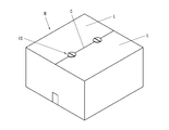
- FIG. 7 is the box B in a state in which the repacking operation has been completed, in which two fasteners 10 are attached.
- the lid L is closed by inserting the double-opening lid L of the box B into the insertion portion 4 on both sides of the connection portion 3 It can be fixed in the state. And since tape T can be cut and the box body B can be unpacked by the cutter part 5 provided in the receiving part 1, it is convenient, without needing other tools from unpacking work to re-packing work. high. Moreover, since the cutter part 5 is provided in the edge part of the rod-shaped receiving part 1, and since it can be used in the same sense as a cutter of a general shape, it is easier to perform the unpacking operation.
- the fastener of patent document 1 there existed a case where the process of inserting the other lid
- the fastener of patent document 2 since the upper presser is a flat thing, there existed a case where the process to rotate with this was difficult.
- the fastener of the present invention can be more easily fixed with the double-sided lid of the box closed. That is, since the connecting portion 3 is a rod having a circular cross section, the insertion between the receiving portion 1 and the pressing portion 2 is performed by inserting the pressing portion 2 into the gap C of the lid L of the both sides of the box B and rotating it.
- the lid L can be inserted into the portion 4 and the lid L can be fixed in a closed state.
- the knobs 6 provided on the receiver 1 are flexible, the knobs 6 on both sides are turned up. By overlapping the tips of the two, it becomes easy to pick with a finger and the fastener can be easily rotated.
- the pressing portion 2 since the pressing portion 2 is rod-shaped, it can be inserted as long as there is a gap C between the two lids L in a state where the double lid L of the box B is closed. Therefore, since the fastener can be attached after the lid L is closed, the operation is easy.
- the lid L in the state which closed the lid L of the double-opening of the box B, when the edge part of both the lids L closely_contacts and there is no clearance gap, the lid L is made into a semi-closed state, and between the lids L The lid L may be completely closed after the pressing portion 2 is inserted into the gap.
- the knob 6 (lid contact part 6) is flat and has a thin thickness, so that it does not hinder the stacking of the box B.
- the second embodiment is different from the first embodiment in the shape of the cutter unit 5.
- the cutter portions 5 of the second embodiment are provided at both end portions in the left-right direction of the receiving portion 1 and are concave toward the center in the left-right direction of the receiving portion 1 in plan view as shown in FIGS. It has a semi-circular shape, and the vertical cross-section viewed from the front is triangular and sharp toward the outer peripheral side.
- the cutter portion 5 is made of hard resin and is integrally formed with the receiving portion 1.
- the cutter unit 5 of the second embodiment formed in this way has the cutting edge 51 with sharp front and rear tips, so that cutting can be performed by pressing the cutting edge 51 against a tape. Since it does not protrude to the outer peripheral side than the lid contact portion 6), it does not touch directly with a finger or the like, which is safe. And the 2nd embodiment of a fastener has the same operation effect as a 1st embodiment in others.
- the third embodiment is different from the first embodiment in the shape of the lid contact portion 6 (pick portion 6).
- the lid contact portion 6 of the third embodiment is flat and extends horizontally in the front and rear direction centering on the receiving portion 1.
- One lid contact portion 6 has a substantially semicircular shape in plan view, and the diameter thereof is along the receiving portion 1, and the receiving portion 1 and the lid contact portions 6 on both the front and back sides It is approximately circular.
- the lid contact portion 6 is made of a soft resin that can be bent upward and downward by human force, and is integrally molded with the receiving portion 1 by two-color molding.
- the entire lid contact portion 6 corresponds to the knob portion, and the lid contact portion 6 is also the knob portion 6.
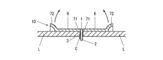
- the front-end direction both ends of knob part 6, ie, tip part 72 on the opposite side of root part 71 joined to receiving part 1, are bent diagonally upward.
- the range of the bent portion is approximately 1 ⁇ 4 of the front-rear width of the knob 6, and is inclined at approximately 45 degrees with respect to the horizontal direction. Therefore, as shown in FIG.
- the knob 6 is made of soft resin, when another box is stacked on the box to which the fastener 10 is attached, the tip 72 (finger hook 72) bent upward obliquely is upward. It is crushed by a box, and the whole knob part 6 becomes flat form. Therefore, there is no hindrance when stacking the boxes.
- the fourth embodiment is different from the first embodiment in the shape of the lid contact portion 6 (pick portion 6).
- the lid contact portion 6 of the fourth embodiment is flat and extends horizontally in the front and back directions centering on the receiving portion 1.
- One lid contact portion 6 has a substantially semicircular shape in plan view, and the diameter thereof is along the receiving portion 1, and the receiving portion 1 and the lid contact portions 6 on both the front and back sides It is approximately circular.
- the lid contact portion 6 is made of a soft resin that can be bent upward and downward by human force, and is integrally molded with the receiving portion 1 by two-color molding.
- the whole of the lid contact portion 6 corresponds to the knob portion, and the lid contact portion 6 is also the knob portion 6.
- tip part 72 on the opposite side of the root part 71 joined to the receiving part 1, are rising in dome shape.
- a substantially semicircular area centering on the leading end points (front and rear end points) of the knob portion 6 is bulged upward in a spherical shell shape centering on the leading end point, and this dome shape
- the front and rear width of the portion is approximately 1 ⁇ 4 of the front and rear width of the knob 6. Therefore, as shown in FIG.
- a 4th embodiment of a fastener has the same operation effect as a 1st embodiment in others.
- the knob 6 is made of soft resin, when another box is stacked on the box to which the fastener 10 is attached, the tip 72 (finger hook 72) raised in a dome shape is at the top. It is crushed by a box, and the whole knob part 6 becomes flat form. Therefore, there is no hindrance when stacking the boxes.
- the fifth embodiment is different from the first embodiment in the shape of the lid contact portion 6 (pick portion 6).
- the lid contact portion 6 of the fifth embodiment is in the form of a flat plate, and extends while curving in the front and back directions centering on the receiving portion 1.
- One lid contact portion 6 has a substantially semicircular shape in plan view, and the diameter thereof is along the receiving portion 1, and the receiving portion 1 and the lid contact portions 6 on both the front and back sides It is approximately circular.
- the lid contact portion 6 is made of a soft resin that can be bent upward and downward by human force, and is integrally molded with the receiving portion 1 by two-color molding.
- the whole of the lid contact portion 6 corresponds to the knob portion, and the lid contact portion 6 is also the knob portion 6.
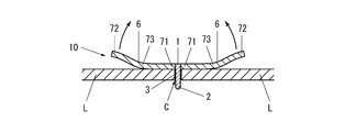
- the root part 71 joined to the receiving part 1 extends in the horizontal direction, and then the middle part 73 curves in an arc shape so as to be convex downward, and further Subsequently, the tip end portion 72 extends in the horizontal direction at substantially the same height as the root portion 71.
- the front-rear width of the curved middle portion 73 is approximately 1 ⁇ 2 of the front-rear width of the knob 6.
- the knob 6 is deformed so that the tip portion 72 ascends as the root portion 71 descends with the intermediate portion 73 as a fulcrum Do. Therefore, as shown in FIG. 15, in a state where the lower surface of the root portion 71 of the knob 6 abuts on the upper surface of the lid L, the distal end 72 separates from the upper surface of the lid L, and the distal end 72 is a finger hook It becomes 72.
- the finger hook portion 72 makes it easy to turn up the picking portion 6 It is easy to do the operation of picking the picker 6 and rotating the clasp 10.
- 5th embodiment of a fastener has an effect similar to 1st embodiment in others.
- the knob 6 is made of soft resin, when another box is stacked on the box to which the fastener 10 is attached, the tip 72 (finger hook 72) separated from the upper surface of the lid L is It is crushed by the upper box, and the whole pick part 6 becomes flat form. Therefore, there is no hindrance when stacking the boxes.
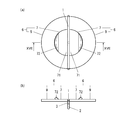
- the sixth embodiment is different from the first embodiment in the shape of the lid contact portion 6 (pick portion 6).
- the lid contact portion 6 of the sixth embodiment is flat and extends horizontally in the front and back directions centering on the receiving portion 1.
- One lid contact portion 6 has a substantially semicircular shape in plan view, and the diameter thereof is along the receiving portion 1, and the receiving portion 1 and the lid contact portions 6 on both the front and back sides It is approximately circular.
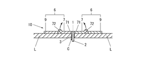
- the lid contact portion 6 is divided into a substantially semicircular inner portion concentric with the outer periphery and having a diameter of approximately 1/2 and an outer portion surrounding the inner portion.
- the inner portion is made of a soft resin that can be bent up and down by human force, and is integrally molded with the receiving portion 1 by two-color molding.
- the outer portion is made of the same hard resin as the receiving portion 1 and is integrally formed with the receiving portion 1. Therefore, in the sixth embodiment, an inner portion which is a part of the lid contact portion 6 corresponds to the knob 7. Further, the outer portion is a fixing portion 9 fixed to the receiving portion 1. And the front-end direction both ends of knob part 7, ie, tip part 72 on the opposite side of root part 71 joined to receiving part 1, are bent diagonally upward.
- the range of the bent portion is approximately 1 ⁇ 4 of the front-rear width of the knob 7 and is inclined at approximately 45 degrees with respect to the horizontal direction.
- the sixth embodiment after inserting the pressing portion 2 into the gap C between the joints of both lids L, putting the finger on the finger hook portion 72 makes it easy to turn up the picking portion 7 It is easy to do the operation of picking the knob 7 and rotating the fastener 10.
- the sixth embodiment of the fastener exhibits the same effects as the first embodiment in the other aspects.
- the knob 7 is made of soft resin, when another box is stacked on the box to which the fastener 10 is attached, the tip portion 72 (the finger hook 72) bent upward obliquely is upward. It is crushed by a box, and the whole knob part 7 becomes flat form. Therefore, there is no hindrance when stacking the boxes.
- the cutter portion may have any shape as long as it is sharp enough to cut the tape, but it is desirable that it be safe to touch with a finger or the like. Further, it may be provided only at one end of the receiving part, or after being provided at both ends, the shape may be made different, such as making one side into a saw shape. Furthermore, the cutter portion may be provided on the pressing portion or the connecting portion. Further, the receiving portion and the lid contacting portion may be separately formed and joined by an adhesive, or the fitting structure corresponding to the receiving portion and the lid contacting portion may be formed and joined by fitting.
- the knob portion is not limited to being flipped up from the front and rear direction with respect to the receiving portion extending in the left and right direction, but may be flipped up from the left and right direction and other directions.
- the joint between the knob and the receiver may be a fold or a hinge and be bendable at that portion.
- the knob may be made of a hard material.
- the material of each part including the knob in this case may be metal instead of resin.
- the finger hook portion may be formed by thickening the tip end portion of the knob portion.
- the box targeted for the fastener is not limited to the one having a double-opening lid on the top surface, but may have a lid on the side surface. In this case, the fastener is attached with the lid contact portion oriented vertically.
Landscapes
- Engineering & Computer Science (AREA)
- Mechanical Engineering (AREA)
- General Engineering & Computer Science (AREA)
- Life Sciences & Earth Sciences (AREA)
- Forests & Forestry (AREA)
- Cartons (AREA)
Abstract
Cet élément de fixation, permettant de fixer un double couvercle d'une boîte dans un état fermé, peut également être utilisé dans une opération de désemballage de la boîte. Cet élément de fixation, qui fixe un double couvercle d'une boîte dans un état fermé, est pourvu d'une partie de réception, d'une partie de pression et d'une partie de liaison. La partie de réception et la partie de pression sont disposées en regard l'une de l'autre, la partie de liaison étant intercalée entre celles-ci. L'espace sur les deux côtés de la partie de liaison, qui se trouve entre la partie de réception et la partie de pression, devient une zone d'insertion pour l'insertion du couvercle de la boîte, et une unité de coupe est disposée sur la partie de réception, la partie de pression ou la partie de liaison.
Priority Applications (3)
| Application Number | Priority Date | Filing Date | Title |
|---|---|---|---|
| EP19743286.7A EP3747788B1 (fr) | 2018-01-29 | 2019-01-24 | Élément de fixation |
| CN201980008342.9A CN111601758A (zh) | 2018-01-29 | 2019-01-24 | 紧固件 |
| US16/770,424 US11498230B2 (en) | 2018-01-29 | 2019-01-24 | Fastner |
Applications Claiming Priority (2)
| Application Number | Priority Date | Filing Date | Title |
|---|---|---|---|
| JP2018-012522 | 2018-01-29 | ||
| JP2018012522A JP6370506B1 (ja) | 2018-01-29 | 2018-01-29 | 留め具 |
Publications (1)
| Publication Number | Publication Date |
|---|---|
| WO2019146708A1 true WO2019146708A1 (fr) | 2019-08-01 |
Family
ID=63104416
Family Applications (2)
| Application Number | Title | Priority Date | Filing Date |
|---|---|---|---|
| PCT/JP2019/002308 Ceased WO2019146709A1 (fr) | 2018-01-29 | 2019-01-24 | Élément de fixation |
| PCT/JP2019/002307 Ceased WO2019146708A1 (fr) | 2018-01-29 | 2019-01-24 | Élément de fixation |
Family Applications Before (1)
| Application Number | Title | Priority Date | Filing Date |
|---|---|---|---|
| PCT/JP2019/002308 Ceased WO2019146709A1 (fr) | 2018-01-29 | 2019-01-24 | Élément de fixation |
Country Status (5)
| Country | Link |
|---|---|
| US (2) | US11498230B2 (fr) |
| EP (2) | EP3747789B1 (fr) |
| JP (1) | JP6370506B1 (fr) |
| CN (2) | CN111655588A (fr) |
| WO (2) | WO2019146709A1 (fr) |
Cited By (1)
| Publication number | Priority date | Publication date | Assignee | Title |
|---|---|---|---|---|
| WO2022085872A1 (fr) * | 2020-10-20 | 2022-04-28 | 주식회사 피코피코 | Dispositif de retenue de boîte |
Families Citing this family (8)
| Publication number | Priority date | Publication date | Assignee | Title |
|---|---|---|---|---|
| CA3051589A1 (fr) * | 2017-01-31 | 2018-08-09 | Gallery Blocks LLC d/b/a Artsy Couture | Ensemble d'affichage d'image et son dispositif de fixation par verrouillage |
| JP6370506B1 (ja) * | 2018-01-29 | 2018-08-08 | 株式会社小泉製作所 | 留め具 |
| GB2579377B (en) * | 2018-11-29 | 2021-06-30 | Pet Mate Ltd | Automatic pet feeder |
| US11267608B1 (en) * | 2019-03-11 | 2022-03-08 | Eco-Latch Systems, LLC | Box closure device |
| US11530072B1 (en) * | 2019-03-11 | 2022-12-20 | Eco-Latch Systems, LLC | Box closure device |
| ES2925423B2 (es) * | 2021-03-22 | 2023-02-24 | Univ Madrid Politecnica | Cierre celulosico con etiqueta adhesiva para embalajes de carton con solapas y procedimiento de uso |
| US11873145B2 (en) * | 2021-04-13 | 2024-01-16 | Armin Brown | Box fastening system |
| US20240017894A1 (en) * | 2022-07-13 | 2024-01-18 | Norma Farris | Device for closing a container to make the container reusable |
Citations (5)
| Publication number | Priority date | Publication date | Assignee | Title |
|---|---|---|---|---|
| JPS5638023U (fr) * | 1979-09-03 | 1981-04-10 | ||
| JP2001301753A (ja) | 2000-04-26 | 2001-10-31 | Yogo Jukin Sangyo Kk | 両開き蓋付き容器用クリップ及び容器の蓋の結合構造 |
| WO2008076866A1 (fr) * | 2006-12-18 | 2008-06-26 | Barsness John G | Fermeture de boîte avec languette articulée |
| JP2014151952A (ja) * | 2013-02-12 | 2014-08-25 | Yozo Shinozaki | 包装箱の封緘方法、部材、組み合せ |
| JP2016043968A (ja) | 2014-08-25 | 2016-04-04 | 篠崎 要蔵 | 封緘具 |
Family Cites Families (25)
| Publication number | Priority date | Publication date | Assignee | Title |
|---|---|---|---|---|
| US1909654A (en) * | 1931-08-03 | 1933-05-16 | Lawrence Paper Co | Box fastener |
| US1958652A (en) * | 1931-11-09 | 1934-05-15 | William H Wrye | Closure fastener |
| US2297771A (en) * | 1939-09-08 | 1942-10-06 | Inland Wire Products Company | Box fastener |
| US3545801A (en) * | 1968-09-09 | 1970-12-08 | John G Barsness | Box closure fastening |
| JPS5110121U (fr) | 1974-07-10 | 1976-01-24 | ||
| US4019764A (en) * | 1974-12-10 | 1977-04-26 | Matsushita Electric Industrial Co., Ltd. | Clamping device adapted to clamp plate-like members |
| JPS5536322Y2 (fr) | 1976-02-14 | 1980-08-27 | ||
| US4339983A (en) * | 1978-02-13 | 1982-07-20 | Matsushita Electric Industrial Co., Ltd. | Clamping device for clamping plate-like members |
| JPS5867726U (ja) | 1981-10-29 | 1983-05-09 | 松下電器産業株式会社 | 板状部材の結合具 |
| US4531670A (en) * | 1984-06-18 | 1985-07-30 | Kupersmit Julius B | Combination clip and seal construction for shipping containers |
| US6230965B1 (en) * | 1996-09-09 | 2001-05-15 | Percy W. Dismukes | Reusable container closure |
| JP3281976B2 (ja) * | 1997-02-12 | 2002-05-13 | 株式会社トーキン | 包装用箱体 |
| US5887782A (en) * | 1997-09-24 | 1999-03-30 | Mueller; Charles J. | High stacking strength automatic corrugated box |
| US6571538B2 (en) * | 1998-03-16 | 2003-06-03 | Afton Enterprises, Inc. | Box flap securing device |
| JP2010006408A (ja) | 2008-06-26 | 2010-01-14 | Toshiba Corp | 係合保持具 |
| US7854372B1 (en) * | 2008-10-08 | 2010-12-21 | Bartone Sr John A | Box closure clip |
| US20120193258A1 (en) * | 2009-10-21 | 2012-08-02 | Deutsche Post Ag | Tamper-Evident Closure for A Box with Alarm Sensor |
| US20120255954A1 (en) * | 2011-04-06 | 2012-10-11 | Barsness John G | Box Closing Insert |
| CN202828292U (zh) * | 2012-09-29 | 2013-03-27 | 泉州市一键网络科技有限公司 | 一种石板样品箱 |
| US8998071B2 (en) * | 2013-05-23 | 2015-04-07 | Stephen Sublett | Three-pronged box flap closure device |
| US9321566B2 (en) * | 2014-05-29 | 2016-04-26 | Tri-Tech Tool & Design Co., Inc. | Box closure apparatus |
| US10364060B2 (en) * | 2016-03-29 | 2019-07-30 | Jeanne Helen Etem | Flat-folding box covers |
| US10633140B1 (en) * | 2017-04-21 | 2020-04-28 | Surpack s.a. | Boxes, blanks and associated methods |
| US10737829B1 (en) * | 2017-12-07 | 2020-08-11 | Eco-Latch Systems, LLC | Box fastener with improved characteristics |
| JP6370506B1 (ja) * | 2018-01-29 | 2018-08-08 | 株式会社小泉製作所 | 留め具 |
-
2018
- 2018-01-29 JP JP2018012522A patent/JP6370506B1/ja active Active
-
2019
- 2019-01-24 US US16/770,424 patent/US11498230B2/en active Active
- 2019-01-24 CN CN201980008380.4A patent/CN111655588A/zh active Pending
- 2019-01-24 CN CN201980008342.9A patent/CN111601758A/zh active Pending
- 2019-01-24 WO PCT/JP2019/002308 patent/WO2019146709A1/fr not_active Ceased
- 2019-01-24 US US16/770,472 patent/US11173618B2/en active Active
- 2019-01-24 EP EP19744051.4A patent/EP3747789B1/fr active Active
- 2019-01-24 EP EP19743286.7A patent/EP3747788B1/fr active Active
- 2019-01-24 WO PCT/JP2019/002307 patent/WO2019146708A1/fr not_active Ceased
Patent Citations (5)
| Publication number | Priority date | Publication date | Assignee | Title |
|---|---|---|---|---|
| JPS5638023U (fr) * | 1979-09-03 | 1981-04-10 | ||
| JP2001301753A (ja) | 2000-04-26 | 2001-10-31 | Yogo Jukin Sangyo Kk | 両開き蓋付き容器用クリップ及び容器の蓋の結合構造 |
| WO2008076866A1 (fr) * | 2006-12-18 | 2008-06-26 | Barsness John G | Fermeture de boîte avec languette articulée |
| JP2014151952A (ja) * | 2013-02-12 | 2014-08-25 | Yozo Shinozaki | 包装箱の封緘方法、部材、組み合せ |
| JP2016043968A (ja) | 2014-08-25 | 2016-04-04 | 篠崎 要蔵 | 封緘具 |
Non-Patent Citations (1)
| Title |
|---|
| See also references of EP3747788A4 |
Cited By (1)
| Publication number | Priority date | Publication date | Assignee | Title |
|---|---|---|---|---|
| WO2022085872A1 (fr) * | 2020-10-20 | 2022-04-28 | 주식회사 피코피코 | Dispositif de retenue de boîte |
Also Published As
| Publication number | Publication date |
|---|---|
| US20200384658A1 (en) | 2020-12-10 |
| US11498230B2 (en) | 2022-11-15 |
| EP3747789C0 (fr) | 2024-05-08 |
| JP2019131197A (ja) | 2019-08-08 |
| EP3747788B1 (fr) | 2023-07-12 |
| EP3747789A4 (fr) | 2021-10-06 |
| EP3747788A1 (fr) | 2020-12-09 |
| EP3747789B1 (fr) | 2024-05-08 |
| US11173618B2 (en) | 2021-11-16 |
| EP3747789A1 (fr) | 2020-12-09 |
| EP3747788A4 (fr) | 2021-09-29 |
| US20210002022A1 (en) | 2021-01-07 |
| EP3747788C0 (fr) | 2023-07-12 |
| JP6370506B1 (ja) | 2018-08-08 |
| WO2019146709A1 (fr) | 2019-08-01 |
| CN111601758A (zh) | 2020-08-28 |
| CN111655588A (zh) | 2020-09-11 |
Similar Documents
| Publication | Publication Date | Title |
|---|---|---|
| WO2019146708A1 (fr) | Élément de fixation | |
| AU2013321880B2 (en) | Storage container | |
| US7708185B2 (en) | Plastic box | |
| WO1988005388A1 (fr) | Trombone | |
| JP2013212879A (ja) | 複合容器 | |
| JP2013163545A (ja) | キャップ付容器、キャップ付検体容器、およびキャップ | |
| US4027386A (en) | Cutting implement | |
| HK40035600A (en) | Fastener | |
| HK40035596A (en) | Fastener | |
| JPH0343182A (ja) | ロボットハンド | |
| JP3621920B2 (ja) | 容器構造 | |
| JP4942162B2 (ja) | 包装体 | |
| JP3223971U (ja) | 食品収納容器のトング付蓋 | |
| CN224061620U (zh) | 一种易撕除吸管包装体 | |
| JP2003335323A (ja) | 開封補助罫入り包装箱 | |
| JPH07215364A (ja) | 容 器 | |
| JP4858012B2 (ja) | 開封構造を備えた筒状容器 | |
| JPH0542069Y2 (fr) | ||
| CN2313914Y (zh) | 开罐器 | |
| JP3126654U (ja) | ダンボール箱の持ち運びハンドル | |
| JPH0513286Y2 (fr) | ||
| JP4239194B2 (ja) | 食品包装用容器 | |
| JP2012001220A (ja) | アンプルカット補助具 | |
| JP2011240414A (ja) | 分銅把持具 | |
| JPH09221143A (ja) | フィルム収納箱 |
Legal Events
| Date | Code | Title | Description |
|---|---|---|---|
| 121 | Ep: the epo has been informed by wipo that ep was designated in this application |
Ref document number: 19743286 Country of ref document: EP Kind code of ref document: A1 |
|
| NENP | Non-entry into the national phase |
Ref country code: DE |
|
| ENP | Entry into the national phase |
Ref document number: 2019743286 Country of ref document: EP Effective date: 20200831 |