WO2019151081A1 - 膜電極接合体及び固体高分子形燃料電池 - Google Patents
膜電極接合体及び固体高分子形燃料電池 Download PDFInfo
- Publication number
- WO2019151081A1 WO2019151081A1 PCT/JP2019/002090 JP2019002090W WO2019151081A1 WO 2019151081 A1 WO2019151081 A1 WO 2019151081A1 JP 2019002090 W JP2019002090 W JP 2019002090W WO 2019151081 A1 WO2019151081 A1 WO 2019151081A1
- Authority
- WO
- WIPO (PCT)
- Prior art keywords
- electrode catalyst
- catalyst layer
- membrane
- electrode assembly
- polymer electrolyte
- Prior art date
- Legal status (The legal status is an assumption and is not a legal conclusion. Google has not performed a legal analysis and makes no representation as to the accuracy of the status listed.)
- Ceased
Links
Images
Classifications
-
- H—ELECTRICITY
- H01—ELECTRIC ELEMENTS
- H01M—PROCESSES OR MEANS, e.g. BATTERIES, FOR THE DIRECT CONVERSION OF CHEMICAL ENERGY INTO ELECTRICAL ENERGY
- H01M8/00—Fuel cells; Manufacture thereof
- H01M8/10—Fuel cells with solid electrolytes
- H01M8/1016—Fuel cells with solid electrolytes characterised by the electrolyte material
- H01M8/1018—Polymeric electrolyte materials
-
- H—ELECTRICITY
- H01—ELECTRIC ELEMENTS
- H01M—PROCESSES OR MEANS, e.g. BATTERIES, FOR THE DIRECT CONVERSION OF CHEMICAL ENERGY INTO ELECTRICAL ENERGY
- H01M4/00—Electrodes
- H01M4/86—Inert electrodes with catalytic activity, e.g. for fuel cells
- H01M4/8663—Selection of inactive substances as ingredients for catalytic active masses, e.g. binders, fillers
- H01M4/8673—Electrically conductive fillers
-
- H—ELECTRICITY
- H01—ELECTRIC ELEMENTS
- H01M—PROCESSES OR MEANS, e.g. BATTERIES, FOR THE DIRECT CONVERSION OF CHEMICAL ENERGY INTO ELECTRICAL ENERGY
- H01M4/00—Electrodes
- H01M4/86—Inert electrodes with catalytic activity, e.g. for fuel cells
- H01M4/90—Selection of catalytic material
- H01M4/9075—Catalytic material supported on carriers, e.g. powder carriers
- H01M4/9083—Catalytic material supported on carriers, e.g. powder carriers on carbon or graphite
-
- H—ELECTRICITY
- H01—ELECTRIC ELEMENTS
- H01M—PROCESSES OR MEANS, e.g. BATTERIES, FOR THE DIRECT CONVERSION OF CHEMICAL ENERGY INTO ELECTRICAL ENERGY
- H01M8/00—Fuel cells; Manufacture thereof
- H01M8/10—Fuel cells with solid electrolytes
- H01M8/1004—Fuel cells with solid electrolytes characterised by membrane-electrode assemblies [MEA]
-
- H—ELECTRICITY
- H01—ELECTRIC ELEMENTS
- H01M—PROCESSES OR MEANS, e.g. BATTERIES, FOR THE DIRECT CONVERSION OF CHEMICAL ENERGY INTO ELECTRICAL ENERGY
- H01M8/00—Fuel cells; Manufacture thereof
- H01M8/10—Fuel cells with solid electrolytes
- H01M2008/1095—Fuel cells with polymeric electrolytes
-
- Y—GENERAL TAGGING OF NEW TECHNOLOGICAL DEVELOPMENTS; GENERAL TAGGING OF CROSS-SECTIONAL TECHNOLOGIES SPANNING OVER SEVERAL SECTIONS OF THE IPC; TECHNICAL SUBJECTS COVERED BY FORMER USPC CROSS-REFERENCE ART COLLECTIONS [XRACs] AND DIGESTS
- Y02—TECHNOLOGIES OR APPLICATIONS FOR MITIGATION OR ADAPTATION AGAINST CLIMATE CHANGE
- Y02E—REDUCTION OF GREENHOUSE GAS [GHG] EMISSIONS, RELATED TO ENERGY GENERATION, TRANSMISSION OR DISTRIBUTION
- Y02E60/00—Enabling technologies; Technologies with a potential or indirect contribution to GHG emissions mitigation
- Y02E60/30—Hydrogen technology
- Y02E60/50—Fuel cells
Definitions
- the present invention relates to a membrane electrode assembly for a polymer electrolyte fuel cell and a polymer electrolyte fuel cell.
- the polymer electrolyte fuel cell includes a membrane electrode assembly in which electrode catalyst layers are disposed on both sides of a solid polymer electrolyte membrane. Fuel cells are required to have stable and improved power generation performance for cost reduction. In order to stabilize and improve the power generation performance, the adhesion between the solid polymer electrolyte membrane and the electrode catalyst layer is improved, and mass transfer such as protons and water at the interface between the solid polymer electrolyte membrane and the electrode catalyst layer is improved. Need to be easy.
- Patent Documents 1 and 2 disclose a membrane electrode assembly in which a 90 ° peel strength at the interface between the solid polymer electrolyte membrane and the electrode catalyst layer is defined. It is described that the stable power generation performance of the membrane electrode assembly can be realized.
- the present invention has been made in view of such circumstances, and has a good adhesion between a solid polymer electrolyte membrane and an electrode catalyst layer, and is capable of stabilizing and improving power generation performance.
- An object of the present invention is to provide a membrane electrode assembly and a polymer electrolyte fuel cell.
- the membrane electrode assembly according to one aspect of the present invention is a membrane electrode assembly in which electrode catalyst layers are disposed on both sides of a solid polymer electrolyte membrane, respectively, and after both electrode catalyst layers are peeled off using an adhesive member
- the total light transmittance when measured is 40% or less, and the total light transmittance of the portion where the electrode catalyst layer is disposed when the total light transmittance of the portion other than the portion where the electrode catalyst layer is disposed is 100%.
- the adhesive member has an adhesive strength measured by pulling the adhesive member attached to the stainless steel plate in a direction that forms an angle of 180 ° with respect to the stainless steel plate and peeling the adhesive member from the stainless steel plate. It is a summary.
- the gist of a solid polymer fuel cell according to another aspect of the present invention is that it comprises the membrane electrode assembly according to the above aspect.
- the adhesiveness of a solid polymer electrolyte membrane and an electrode catalyst layer is favorable, and the membrane electrode assembly and solid polymer fuel cell which can stabilize and improve electric power generation performance can be provided. .
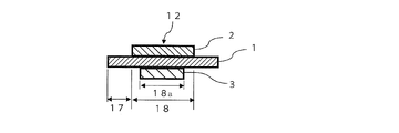
- a membrane electrode assembly 12 As shown in FIG. 1, a membrane electrode assembly 12 according to an embodiment of the present invention (hereinafter referred to as “this embodiment”) includes a solid polymer electrolyte membrane 1 and one surface of the solid polymer electrolyte membrane 1.
- the electrode catalyst layer 2 on the cathode side formed in the above and the electrode catalyst layer 3 on the anode side formed on the other surface of the solid polymer electrolyte membrane 1 are provided.
- the membrane electrode assembly 12 includes a portion 18 where the electrode catalyst layers 2 and 3 are disposed (hereinafter referred to as “electrode catalyst layer disposed portion 18”) and a portion 17 where the electrode catalyst layers 2 and 3 are not disposed (hereinafter referred to as “electrode catalyst layers 2 and 3”). And “denoted as a portion 17 other than the portion where the electrode catalyst layer is disposed”). And as for membrane electrode assembly 12, it is preferable that the total light transmittance of the arrangement
- the total light transmittance of the arrangement portion 18 of the electrode catalyst layer is 40% or less means that a part of the electrode catalyst layers 2 and 3 is formed on the surface of the solid polymer electrolyte membrane 1 after the electrode catalyst layers 2 and 3 are peeled off. Means that it remains without peeling. Therefore, such a membrane electrode assembly 12 has good adhesion between the solid polymer electrolyte membrane 1 and the electrode catalyst layers 2 and 3, and a polymer electrolyte fuel cell is manufactured using the membrane electrode assembly 12. Then, high power generation performance can be obtained stably.
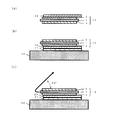
- Step 1 As shown in FIG. 2 (a), the single-sided adhesive tape 20 is adhered to the surface of one electrode catalyst layer 2 of the membrane electrode assembly 12, and the single-sided adhesive tape 20 is rubbed firmly with a fingertip.
- the single-sided pressure-sensitive adhesive tape 20 is preferably transparent so that it can be confirmed whether or not the whole is adhered. Moreover, it is desirable not to adhere a tape other than the electrode catalyst layer 2 so that peeling is easy.
- the single-sided adhesive tape 20 is in accordance with the industrial standardization method (JIS K 5600-5-6).
- Step 3 As shown in FIG. 2 (c), the solid polymer electrolyte membrane 1 of the membrane electrode assembly 12 is pulled at an angle as close to 60 ° as possible with respect to the plane of the fixing base 30 for 0.5 seconds. It peels reliably from the electrode catalyst layer 2 in the time of 1.0 second or less.
- Step 4 The electrode catalyst layer 3 on the side opposite to the peeled electrode catalyst layer 2 is also peeled in the same procedure as in the above step 1-3.
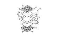
- the polymer electrolyte fuel cell faces the cathode-side electrode catalyst layer 2 and the anode-side electrode catalyst layer 3 of the membrane electrode assembly 12 so as to diffuse the air electrode side gas.
- the layer 4 and the fuel electrode side gas diffusion layer 5 are respectively disposed.
- the cathode 6 is composed of the cathode-side electrode catalyst layer 2 and the air electrode-side gas diffusion layer 4, and the anode-side electrode catalyst layer 3 and the fuel electrode-side gas diffusion layer 5 form the fuel electrode 7. Composed.
- a single cell polymer electrolyte fuel cell 11 is constructed by sandwiching the air electrode 6 and the fuel electrode 7 by a pair of separators 10 and 10.
- the pair of separators 10 are made of a conductive and gas-impermeable material, and are arranged to face the air electrode side gas diffusion layer 4 or the fuel electrode side gas diffusion layer 5 and are used for the reaction gas circulation gas flow path. 8 and a cooling water passage 9 for circulating the cooling water disposed on the main surface facing the gas passage 8.
- an oxidant such as air or oxygen is supplied to the air electrode 6 through the gas flow path 8 of one separator 10, and hydrogen is passed through the gas flow path 8 of the other separator 10.
- the fuel gas or organic fuel containing the fuel is supplied to the fuel electrode 7 to generate power.
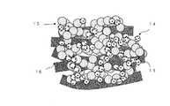
- the electrode catalyst layers 2 and 3 of the present embodiment have a structure containing a catalyst 13, carbon particles 14, polymer electrolyte 15, and carbon fibers 16, for example, as shown in the cross-sectional view of FIG. 4.
- the polymer electrolyte 15 is not particularly limited as long as it has ion conductivity, but considering the adhesion between the electrode catalyst layers 2 and 3 and the solid polymer electrolyte membrane 1, the same material as the solid polymer electrolyte membrane 1 is used. Is preferably selected.
- the polymer electrolyte 15 can be a fluorine resin or a hydrocarbon resin.
- fluorine-based resin examples include Nafion (registered trademark) manufactured by DuPont, and examples of the hydrocarbon-based resin include engineering plastics or those obtained by introducing a sulfonic acid group into a copolymer thereof. .
- a platinum group element As the catalyst 13, a platinum group element, a metal, an alloy thereof, an oxide, a double oxide, or the like can be used.
- Platinum group elements include platinum, palladium, ruthenium, iridium, rhodium, and osmium.
- the metal include iron, lead, copper, chromium, cobalt, nickel, manganese, vanadium, molybdenum, gallium, and aluminum. Among these, platinum or a platinum alloy is preferable as the catalyst 13.
- the activity of the catalyst 13 will fall if the particle size of these catalysts 13 is too large, and the stability of the catalyst 13 will fall if it is too small, 0.5 nm or more and 20 nm or less are preferable, and 1 nm or more and 5 nm or less are further. preferable.
- the electrode catalyst layers 2 and 3 may or may not contain the carbon fiber 16.
- the carbon fiber 16 When the carbon fiber 16 is contained, the electrode catalyst layers 2 and 3 are easily formed, and the mechanical strength can be improved. Moreover, the power generation performance and durability of the membrane electrode assembly 12 can be improved.
- the carbon fiber 16 for example, carbon fiber, carbon nanofiber, and carbon nanotube can be used. Carbon nanofibers and carbon nanotubes are preferred.
- the catalyst 13 may be supported on the carbon fibers 16 or may be supported on both the carbon particles 14 and the carbon fibers 16. However, it is preferable to support the catalyst 13 on the carbon particles 14 because the gap formed by the carbon fibers 16 serves as a discharge path for generated water by power generation, and the drainage of the electrode catalyst layers 2 and 3 is improved.
- the electrode catalyst layers 2 and 3 can be produced by preparing a catalyst layer slurry, and coating and drying the prepared catalyst layer slurry on a substrate or the like.
- the catalyst layer slurry is composed of a catalyst 13, carbon particles 14, a polymer electrolyte 15, carbon fibers 16, and a solvent.
- the kind of solvent is not specifically limited, What can disperse
- Solvents used include water, alcohols such as methanol, ethanol, 1-propanol, 2-propanol, 1-butanol, 2-butanol, isobutyl alcohol, tert-butyl alcohol, acetone, methyl ethyl ketone, methyl propyl ketone, Examples thereof include ketones such as methyl butyl ketone, methyl isobutyl ketone, methyl amyl ketone, pentanone, heptanone, cyclohexanone, methyl cyclohexanone, acetonyl acetone, diethyl ketone, dipropyl ketone, and diisobutyl ketone.
- alcohols such as methanol, ethanol, 1-propanol, 2-propanol, 1-butanol, 2-butanol, isobutyl alcohol, tert-butyl alcohol, acetone, methyl ethyl ketone, methyl
- Solvents include tetrahydrofuran, tetrahydropyran, dioxane, diethylene glycol dimethyl ether, anisole, methoxytoluene, diethyl ether, dipropyl ether, dibutyl ether and other ethers, isopropylamine, butylamine, isobutylamine, cyclohexylamine, diethylamine, aniline, etc.
- Amines such as propyl formate, isobutyl formate, amyl formate, methyl acetate, ethyl acetate, propyl acetate, butyl acetate, isobutyl acetate, pentyl acetate, isopentyl acetate, methyl propionate, ethyl propionate, butyl propionate Can also be illustrated.
- glycol and glycol ether solvents include ethylene glycol, diethylene glycol, propylene glycol, ethylene glycol monomethyl ether, ethylene glycol dimethyl ether, ethylene glycol diethyl ether, diacetone alcohol, 1-methoxy-2-propanol, and 1-ethoxy-2. -Propanol and the like.
- Examples of the method for applying the slurry for the catalyst layer include a doctor blade method, a die coating method, a dipping method, a screen printing method, a laminator roll coating method, and a spray method, but are not particularly limited.
- Examples of the method for drying the catalyst layer slurry include warm air drying, IR drying (infrared drying), and the like.
- the drying temperature is 40 ° C. or higher and 200 ° C. or lower, preferably 40 ° C. or higher and 120 ° C. or lower.
- the drying time is 0.5 minutes or more and 1 hour or less, preferably 1 minute or more and 30 minutes or less.
- the membrane electrode assembly 12 of the present embodiment has the total light beam of the portion 17 other than the portion where the electrode catalyst layer is disposed after the electrode catalyst layers 2 and 3 are peeled off using an adhesive member such as an adhesive tape.
- an adhesive member such as an adhesive tape.
- the adhesion between the solid polymer electrolyte membrane 1 and the electrode catalyst layers 2 and 3 is good, and the membrane / electrode assembly 12 for a polymer electrolyte fuel cell capable of stabilizing and improving the power generation performance.
- the membrane electrode assembly 12 of this embodiment is very suitable for application to a polymer electrolyte fuel cell, for example.
- [Peeling method of electrode catalyst layer] It implemented according to the peeling method of said electrode catalyst layer.
- the single-sided adhesive tape 20 cello tape (registered trademark) manufactured by Nichiban Co., Ltd. was used.
- the double-sided adhesive tape 21 Nichiban (registered trademark) manufactured by Nichiban Co., Ltd. was used.
- the adhesive strength of the single-sided adhesive tape 20 was 3.93 N / 10 mm.
- the adhesive strength of the double-sided adhesive tape 21 was 6.30 N / 10 mm.
- a gas diffusion layer (SIGRACE (registered trademark) 35BC manufactured by SGL) was disposed outside the electrode catalyst layer, and power generation characteristics were evaluated using a commercially available JARI standard cell.
- the cell temperature was 80 ° C., and hydrogen (100% RH) was supplied to the anode and air (100% RH) was supplied to the cathode.
- Catalyst layer slurry 1 20 g of platinum-supported carbon (TEC10E50E manufactured by Tanaka Kikinzoku Kogyo Co., Ltd.) is placed in a container, mixed with water, and then 1-propanol and an electrolyte (Nafion (registered trademark) dispersion of Wako Pure Chemical Industries, Ltd.) are added. By stirring, slurry 1 for the catalyst layer was obtained.
- Catalyst layer slurry 2 20 g of platinum-supported carbon (TEC10E50E manufactured by Tanaka Kikinzoku Kogyo Co., Ltd.) is placed in a container, and after adding water and mixing, 1-propanol, electrolyte (Nafion (registered trademark) dispersion of Wako Pure Chemical Industries, Ltd.), As a carbon fiber, 10 g of carbon nanofiber (trade name “VGCF” manufactured by Showa Denko KK, fiber diameter: about 150 nm, fiber length: about 10 ⁇ m) was added and stirred to obtain catalyst layer slurry 2.
- VGCF carbon nanofiber
- Catalyst layer slurry 3 20 g of platinum-supported carbon (TEC10E50E manufactured by Tanaka Kikinzoku Kogyo Co., Ltd.) is placed in a container, and after adding water and mixing, 1-propanol, electrolyte (Nafion (registered trademark) dispersion of Wako Pure Chemical Industries, Ltd.), As a carbon fiber, 10 g of carbon nanotube (fiber diameter: about 1 nm, fiber length: about 1 ⁇ m) was added and stirred to obtain catalyst layer slurry 3.
- TEC10E50E manufactured by Tanaka Kikinzoku Kogyo Co., Ltd. As a carbon fiber, 10 g of carbon nanotube (fiber diameter: about 1 nm, fiber length: about 1 ⁇ m) was added and stirred to obtain catalyst layer slurry 3.
- Example 1 The catalyst layer slurry 1 is applied to a polyethylene terephthalate substrate (hereinafter referred to as “PET substrate”) to form an electrode catalyst layer, and the electrode catalyst layer is subjected to thermocompression bonding at 120 ° C. to form a solid polymer electrolyte membrane (
- PET substrate polyethylene terephthalate substrate
- the membrane electrode assembly of Example 1 was obtained by transferring to Nafion 212) manufactured by DuPont.
- Example 4 The catalyst layer slurry 3 was applied to a solid polymer electrolyte membrane (Nafion 212 manufactured by DuPont) by a die coating method, and dried in an oven at 80 ° C. to obtain a membrane electrode assembly of Example 4.
- a solid polymer electrolyte membrane Nafion 212 manufactured by DuPont
- Comparative Example 1 The catalyst layer slurry 1 is applied to a PET substrate to form an electrode catalyst layer, and this electrode catalyst layer is transferred to a solid polymer electrolyte membrane (DuPont, Nafion 212) by thermocompression bonding at 90 ° C. The membrane electrode assembly of Comparative Example 1 was obtained.
- a solid polymer electrolyte membrane DuPont, Nafion 212
- Comparative Example 2 The catalyst layer slurry 1 is applied to a PET substrate to form an electrode catalyst layer, and this electrode catalyst layer is transferred to a solid polymer electrolyte membrane (Nafion 212 manufactured by DuPont) by thermocompression bonding at 70 ° C. The membrane electrode assembly of Comparative Example 2 was obtained.
- a solid polymer electrolyte membrane Nafion 212 manufactured by DuPont
- ⁇ is shown when the total light transmittance is 40% or less, and “x” is shown otherwise.
- ⁇ is indicated when the 90 ° peel strength is 0.1 N / cm or more, “ ⁇ ” is indicated, and when it is less than 0.1 N / cm, “X” is indicated.
- the power generation performance is indicated by “ ⁇ ” when the voltage when the current density is 1.0 A / cm 2 is 0.6 V or more, and “X” when the voltage is less than 0.6 V.
- the power generation performance after the cycle test was evaluated based on the same criteria as described above.
Landscapes
- Chemical & Material Sciences (AREA)
- Chemical Kinetics & Catalysis (AREA)
- Electrochemistry (AREA)
- General Chemical & Material Sciences (AREA)
- Engineering & Computer Science (AREA)
- Life Sciences & Earth Sciences (AREA)
- Manufacturing & Machinery (AREA)
- Sustainable Development (AREA)
- Sustainable Energy (AREA)
- Materials Engineering (AREA)
- Fuel Cell (AREA)
- Inert Electrodes (AREA)
Abstract
固体高分子電解質膜と電極触媒層との密着性が良好であり、発電性能の安定や向上が可能な固体高分子形燃料電池用の膜電極接合体を提供する。膜電極接合体(12)は、固体高分子電解質膜(1)の両面にそれぞれ電極触媒層(2,3)が配置されたものであって、粘着部材(20)を用いて両電極触媒層(2,3)を剥離した後に測定した場合の全光線透過率が40%以下である。全光線透過率は、電極触媒層の配置部分以外の部分(17)の全光線透過率を100%とした場合の、電極触媒層の配置部分(18)の全光線透過率である。粘着部材(20)は、ステンレス鋼板に貼り付けた粘着部材(20)をステンレス鋼板に対して180°の角度をなす方向に引っ張りステンレス鋼板から剥離させて測定した粘着力が3N/10mm以上である。
Description
本発明は、固体高分子形燃料電池用の膜電極接合体及び固体高分子形燃料電池に関する。
固体高分子形燃料電池は、固体高分子電解質膜の両面にそれぞれ電極触媒層が配置された膜電極接合体を備えている。燃料電池は、低コスト化に向けて、発電性能の安定や向上が望まれている。発電性能の安定や向上のためには、固体高分子電解質膜と電極触媒層との密着性を向上させて、固体高分子電解質膜と電極触媒層との界面におけるプロトンや水等の物質移動を容易にする必要がある。
特許文献1、2には、固体高分子電解質膜と電極触媒層との界面の90°剥離強度が規定された膜電極接合体が開示されており、90°剥離強度が規定値以上であれば、膜電極接合体の安定した発電性能を実現できると記載されている。
特許文献1、2には、固体高分子電解質膜と電極触媒層との界面の90°剥離強度が規定された膜電極接合体が開示されており、90°剥離強度が規定値以上であれば、膜電極接合体の安定した発電性能を実現できると記載されている。
しかしながら、電極触媒層は脆く、剥離の際に電極触媒層内の凝集破壊が起こり易い。そのため、電極触媒層を固体高分子電解質膜から剥離する前に電極触媒層自体が破壊される。したがって、固体高分子電解質膜と電極触媒層との界面の90°剥離強度を正確に評価することは困難であった。
本発明は、このような事情に鑑みてなされたものであり、固体高分子電解質膜と電極触媒層との密着性が良好であり、発電性能の安定や向上が可能な固体高分子形燃料電池用の膜電極接合体及び固体高分子形燃料電池を提供することを目的とする。
本発明は、このような事情に鑑みてなされたものであり、固体高分子電解質膜と電極触媒層との密着性が良好であり、発電性能の安定や向上が可能な固体高分子形燃料電池用の膜電極接合体及び固体高分子形燃料電池を提供することを目的とする。
本発明の一態様に係る膜電極接合体は、固体高分子電解質膜の両面にそれぞれ電極触媒層が配置された膜電極接合体であって、粘着部材を用いて両電極触媒層を剥離した後に測定した場合の全光線透過率が40%以下であり、全光線透過率は、電極触媒層の配置部分以外の部分の全光線透過率を100%とした場合の、電極触媒層の配置部分の全光線透過率であり、粘着部材は、ステンレス鋼板に貼り付けた粘着部材をステンレス鋼板に対して180°の角度をなす方向に引っ張りステンレス鋼板から剥離させて測定した粘着力が3N/10mm以上であることを要旨とする。
本発明の他の態様に係る固体高分子形燃料電池は、上記一態様に係る膜電極接合体を備えることを要旨とする。
本発明の他の態様に係る固体高分子形燃料電池は、上記一態様に係る膜電極接合体を備えることを要旨とする。
本発明によれば、固体高分子電解質膜と電極触媒層との密着性が良好であり、発電性能の安定や向上が可能な膜電極接合体及び固体高分子形燃料電池を提供することができる。
以下、本発明の実施形態について、図面を参照しつつ説明する。なお、本発明は、以下に記載する各実施の形態に限定されるものではなく、当業者の知識に基づいて設計の変更等の変形を加えることも可能であり、そのような変形が加えられた実施の形態も本発明の範囲に含まれるものである。
(膜電極接合体)
図1に示すように、本発明の実施の形態(以下「本実施形態」と記す)に係る膜電極接合体12は、固体高分子電解質膜1と、固体高分子電解質膜1の一方の面に形成されたカソード側の電極触媒層2と、固体高分子電解質膜1の他方の面に形成されたアノード側の電極触媒層3と、を備えた構造となっている。
図1に示すように、本発明の実施の形態(以下「本実施形態」と記す)に係る膜電極接合体12は、固体高分子電解質膜1と、固体高分子電解質膜1の一方の面に形成されたカソード側の電極触媒層2と、固体高分子電解質膜1の他方の面に形成されたアノード側の電極触媒層3と、を備えた構造となっている。
膜電極接合体12は、電極触媒層2,3が配置された部分18(以下「電極触媒層の配置部分18」と記す)と、電極触媒層2,3が配置されていない部分17(以下「電極触媒層の配置部分以外の部分17」と記す)とに区分することができる。そして、膜電極接合体12は、粘着部材を用いて電極触媒層2,3を剥離した後に測定した場合の電極触媒層の配置部分18の全光線透過率が40%以下であることが好ましく、20%以下であることがより好ましい。なお、この全光線透過率は、電極触媒層の配置部分以外の部分17の全光線透過率を100%とした場合の値(相対値)である。また、電極触媒層2,3の面積が異なる場合は、両面に電極触媒層が配置されている部分18aの全光線透過率を用いる。
電極触媒層の配置部分18の全光線透過率が40%以下を示すということは、電極触媒層2,3を剥離した後に固体高分子電解質膜1の表面に電極触媒層2,3の一部が剥離せず残存していることを意味する。よって、このような膜電極接合体12は、固体高分子電解質膜1と電極触媒層2,3との密着性が良好であり、膜電極接合体12を用いて固体高分子形燃料電池を製造すれば、高い発電性能を安定して得ることができる。
[電極触媒層の剥離方法]
以下に、粘着部材を用いた電極触媒層2,3の剥離方法を説明する。なお、以下に示す例では粘着部材の一例として片面粘着テープを採用しているが、粘着部材はこれに限定されるものではない。
以下に、粘着部材を用いた電極触媒層2,3の剥離方法を説明する。なお、以下に示す例では粘着部材の一例として片面粘着テープを採用しているが、粘着部材はこれに限定されるものではない。
(工程1)図2の(a)に示すように、片面粘着テープ20を膜電極接合体12の一方の電極触媒層2の表面に粘着させ、指先でしっかりと片面粘着テープ20をこする。片面粘着テープ20は、全体が接着しているか確認ができるように透明なものが好ましい。また、剥離がし易いように、電極触媒層2以外にテープを接着させないことが望ましい。なお、片面粘着テープ20は、工業標準化法(JIS K 5600-5-6)に準じたものを用いる。
(工程2)図2の(b)に示すように、両面粘着テープ21を用いて、膜電極接合体12の片面粘着テープ側を固定台30の平面上に固定する。固定台30は、剥離時に膜電極接合体12の固定を維持できるものであれば良く、作業台又は金属板等が挙げられる。なお、両面粘着テープ21は、片面粘着テープ20と同等以上の粘着力を有するものを用いる。
(工程3)図2の(c)に示すように、膜電極接合体12の固体高分子電解質膜1を、固定台30の平面に対してできるだけ60°に近い角度で引っ張り、0.5秒以上1.0秒以下の時間で電極触媒層2から確実に剥離する。
(工程4)剥離した電極触媒層2とは反対側の電極触媒層3についても、上記の工程1-3と同様の手順で剥離を行う。
(工程4)剥離した電極触媒層2とは反対側の電極触媒層3についても、上記の工程1-3と同様の手順で剥離を行う。
片面粘着テープ20の粘着力を、固体高分子電解質膜1と電極触媒層2,3との界面の粘着力よりも高くすることで、電極触媒層2,3のみを剥離することができるため好ましい。片面粘着テープ20の粘着力は、ステンレス鋼板に片面粘着テープ20を貼り付け、ステンレス鋼板に対して180°の角度をなす方向に引っ張り、ステンレス鋼板から片面粘着テープ20を剥離させて測定した粘着力(180°剥離強度)である。このときの粘着力は、3N/10mm以上であることが好ましい。
[全光線透過率の測定方法]
全光線透過率は、ヘイズメーターを用いて厚さ方向において測定を行う。電極触媒層の配置部分以外の部分17の全光線透過率を測定し、その測定値を基準値(100%)とする。次に、工程1-4により作製されたサンプルを、電極触媒層の配置部分18が測定範囲に納まるようにヘイズメーターに設置し、電極触媒層の配置部分18の全光線透過率を測定する。電極触媒層の配置部分18については、測定箇所を変えて3回測定を行い、それらの平均値を電極触媒層の配置部分18の全光線透過率とする。
全光線透過率は、ヘイズメーターを用いて厚さ方向において測定を行う。電極触媒層の配置部分以外の部分17の全光線透過率を測定し、その測定値を基準値(100%)とする。次に、工程1-4により作製されたサンプルを、電極触媒層の配置部分18が測定範囲に納まるようにヘイズメーターに設置し、電極触媒層の配置部分18の全光線透過率を測定する。電極触媒層の配置部分18については、測定箇所を変えて3回測定を行い、それらの平均値を電極触媒層の配置部分18の全光線透過率とする。
(固体高分子形燃料電池)
本実施形態の固体高分子形燃料電池は、図3に示すように、膜電極接合体12のカソード側の電極触媒層2及びアノード側の電極触媒層3と対向して、空気極側ガス拡散層4及び燃料極側ガス拡散層5がそれぞれ配置されている。これにより、カソード側の電極触媒層2と空気極側ガス拡散層4とから空気極6が構成されると共に、アノード側の電極触媒層3と燃料極側ガス拡散層5とで燃料極7が構成される。
本実施形態の固体高分子形燃料電池は、図3に示すように、膜電極接合体12のカソード側の電極触媒層2及びアノード側の電極触媒層3と対向して、空気極側ガス拡散層4及び燃料極側ガス拡散層5がそれぞれ配置されている。これにより、カソード側の電極触媒層2と空気極側ガス拡散層4とから空気極6が構成されると共に、アノード側の電極触媒層3と燃料極側ガス拡散層5とで燃料極7が構成される。
そして、空気極6及び燃料極7を一組のセパレータ10,10により挟持することで、単セルの固体高分子形燃料電池11が構成される。一組のセパレータ10は、導電性で且つガス不透過性の材料からなり、空気極側ガス拡散層4又は燃料極側ガス拡散層5に面して配置された反応ガス流通用のガス流路8と、ガス流路8と相対する主面に配置された冷却水流通用の冷却水流路9と、を備える。
この固体高分子形燃料電池11は、一方のセパレータ10のガス流路8を通って空気や酸素などの酸化剤が空気極6に供給され、他方のセパレータ10のガス流路8を通って水素を含む燃料ガス又は有機物燃料が燃料極7に供給されることによって、発電するようになっている。
(電極触媒層)
本実施形態の電極触媒層2、3は、例えば図4の断面図に示すように、触媒13、炭素粒子14、高分子電解質15、及び炭素繊維16を含有する構造体となっている。
高分子電解質15としては、イオン伝導性を有するものであればよいが、電極触媒層2,3と固体高分子電解質膜1との密着性を考えると、固体高分子電解質膜1と同質の材料を選択することが好ましい。例えば、高分子電解質15にはフッ素系樹脂や炭化水素系樹脂が使用できる。フッ素系樹脂としては、例えば、デュポン社製のNafion(登録商標)が挙げられ、炭化水素系樹脂としては、例えば、エンジニアリングプラスチック、又はその共重合体にスルホン酸基を導入したものなどが挙げられる。
本実施形態の電極触媒層2、3は、例えば図4の断面図に示すように、触媒13、炭素粒子14、高分子電解質15、及び炭素繊維16を含有する構造体となっている。
高分子電解質15としては、イオン伝導性を有するものであればよいが、電極触媒層2,3と固体高分子電解質膜1との密着性を考えると、固体高分子電解質膜1と同質の材料を選択することが好ましい。例えば、高分子電解質15にはフッ素系樹脂や炭化水素系樹脂が使用できる。フッ素系樹脂としては、例えば、デュポン社製のNafion(登録商標)が挙げられ、炭化水素系樹脂としては、例えば、エンジニアリングプラスチック、又はその共重合体にスルホン酸基を導入したものなどが挙げられる。
触媒13としては、白金族元素、金属又はこれらの合金、又は酸化物、複酸化物等が使用できる。白金族元素としては、白金、パラジウム、ルテニウム、イリジウム、ロジウム、オスミウムがある。金属としては、鉄、鉛、銅、クロム、コバルト、ニッケル、マンガン、バナジウム、モリブデン、ガリウム、アルミニウムなどが例示できる。その中でも、触媒13としては白金や白金合金が好ましい。また、これらの触媒13の粒径は、大きすぎると触媒13の活性が低下し、小さすぎると触媒13の安定性が低下するため、0.5nm以上20nm以下が好ましく、1nm以上5nm以下がさらに好ましい。
炭素粒子14としては、微粒子状で導電性を有し、触媒13に侵されないものであればどのようなものでも構わない。炭素粒子14の粒径は、小さすぎると電子伝導パスが形成されにくくなり、また、大きすぎると電極触媒層2,3が厚くなり抵抗が増加することで、出力特性が低下したりする。そのため、炭素粒子14の粒径は、10nm以上1000nm以下程度が好ましく、10nm以上100nm以下がさらに好ましい。
炭素粒子14には、触媒13が担持されていることが好ましい。高表面積の炭素粒子14に触媒13を担持することで、高密度で触媒13が担持でき、触媒活性を向上させることができる。
炭素粒子14には、触媒13が担持されていることが好ましい。高表面積の炭素粒子14に触媒13を担持することで、高密度で触媒13が担持でき、触媒活性を向上させることができる。
電極触媒層2,3には、炭素繊維16が含まれていなくても良く、含まれていても良い。炭素繊維16が含まれていると、電極触媒層2,3が形成しやすく、機械的強度も向上させることができる。また、膜電極接合体12の発電性能、耐久性を向上させることができる。
炭素繊維16としては、例えばカーボンファイバー、カーボンナノファイバー、カーボンナノチューブが使用できる。好ましくは、カーボンナノファイバー、カーボンナノチューブである。
炭素繊維16としては、例えばカーボンファイバー、カーボンナノファイバー、カーボンナノチューブが使用できる。好ましくは、カーボンナノファイバー、カーボンナノチューブである。
炭素繊維16の繊維径は、0.5nm以上500nm以下が好ましく、10nm以上300nm以下がより好ましい。上記範囲にすることにより、電極触媒層2,3内の空孔を増加させることができ、高出力化が可能になる。
炭素繊維16の繊維長は、1μm以上200μm以下が好ましく、1μm以上50μm以下がより好ましい。上記範囲にすることにより、電極触媒層2,3の強度を高めることができ、電極触媒層2,3の形成時にクラックが生じることを抑制できる。また、電極触媒層2,3内の空孔を増加させることができ、高出力化が可能になる。
炭素繊維16の繊維長は、1μm以上200μm以下が好ましく、1μm以上50μm以下がより好ましい。上記範囲にすることにより、電極触媒層2,3の強度を高めることができ、電極触媒層2,3の形成時にクラックが生じることを抑制できる。また、電極触媒層2,3内の空孔を増加させることができ、高出力化が可能になる。
触媒13を炭素粒子14に担持させた場合について説明したが、触媒13を炭素繊維16に担持させてもよく、さらに炭素粒子14及び炭素繊維16の両方に担持させてもよい。ただし、触媒13を炭素粒子14に担持させると、炭素繊維16によって作られた隙間が発電による生成水の排出経路となり、電極触媒層2,3の排水性が向上するため、好ましい。
電極触媒層2,3の厚さは、30μm以下が好ましく、10μm以下がより好ましい。厚さが30μmより大きいと、電極触媒層2,3の抵抗が大きくなり、発電性能が低下する。また、電極触媒層2,3にクラックが生じ易くなる。
電極触媒層2,3の厚さは5μm以上が好ましい。厚さが5μmよりも薄い場合には、層厚にばらつきが生じ易くなり、内部の触媒13や高分子電解質15が不均一となりやすい。電極触媒層2,3の表面のひび割れや、厚さの不均一性は、燃料電池として使用し、長期に渡り運転した際の耐久性に悪影響を及ぼす可能性が高いため、好ましくない。また、電極触媒層2,3内において、発電による生成水濃度が高くなり易く、フラッディングが生じ易く、発電性能が低下するため、好ましくない。
電極触媒層2,3の厚さは5μm以上が好ましい。厚さが5μmよりも薄い場合には、層厚にばらつきが生じ易くなり、内部の触媒13や高分子電解質15が不均一となりやすい。電極触媒層2,3の表面のひび割れや、厚さの不均一性は、燃料電池として使用し、長期に渡り運転した際の耐久性に悪影響を及ぼす可能性が高いため、好ましくない。また、電極触媒層2,3内において、発電による生成水濃度が高くなり易く、フラッディングが生じ易く、発電性能が低下するため、好ましくない。
(電極触媒層の製造方法)
電極触媒層2,3は、触媒層用スラリーを作製し、作製した触媒層用スラリーを基材などに塗工・乾燥することで製造できる。触媒層用スラリーは、触媒13、炭素粒子14、高分子電解質15、炭素繊維16及び溶媒からなる。溶媒の種類は特に限定されないが、高分子電解質15を分散又は溶解できるものが好ましい。
電極触媒層2,3は、触媒層用スラリーを作製し、作製した触媒層用スラリーを基材などに塗工・乾燥することで製造できる。触媒層用スラリーは、触媒13、炭素粒子14、高分子電解質15、炭素繊維16及び溶媒からなる。溶媒の種類は特に限定されないが、高分子電解質15を分散又は溶解できるものが好ましい。
用いられる溶媒としては、水や、メタノール、エタノール、1-プロパノール、2-プロパノール、1-ブタノール、2-ブタノール、イソブチルアルコール、tert-ブチルアルコール等のアルコール類や、アセトン、メチルエチルケトン、メチルプロピルケトン、メチルブチルケトン、メチルイゾブチルケトン、メチルアミルケトン、ペンタノン、へプタノン、シクロヘキサノン、メチルシクロヘキサノン、アセトニルアセトン、ジエチルケトン、ジプロピルケトン、ジイソブチルケトンなどのケトン類を例示できる。
また、溶媒として、テトラヒドロフラン、テトラヒドロピラン、ジオキサン、ジエチレングリコールジメチルエーテル、アニソール、メトキシトルエン、ジエチルエーテル、ジプロピルエーテル、ジブチルエーテル等のエーテル類や、イソプロピルアミン、ブチルアミン、イソブチルアミン、シクロヘキシルアミン、ジエチルアミン、アニリンなどのアミン類や、蟻酸プロピル、蟻酸イソブチル、蟻酸アミル、酢酸メチル、酢酸エチル、酢酸プロピル、酢酸ブチル、酢酸イソブチル、酢酸ペンチル、酢酸イソペンチル、プロピオン酸メチル、プロピオン酸エチル、プロピオン酸ブチルなどのエステル類も例示することができる。
さらに、溶媒として、酢酸、プロピオン酸、ジメチルホルムアミド、ジメチルアセトアミド、N-メチルピロリドン等を用いてもよい。また、グリコール、グリコールエーテル系溶媒としては、エチレングリコール、ジエチレングリコール、プロピレングリコール、エチレングリコールモノメチルエーテル、エチレングリコールジメチルエーテル、エチレングリコールジエチルエーテル、ジアセトンアルコール、1-メトキシ-2-プロパノール、1-エトキシ-2-プロパノールなどが挙げられる。
触媒層用スラリーの塗工方法としては、ドクターブレード法、ダイコーティング法、ディッピング法、スクリーン印刷法、ラミネータロールコーティング法、スプレー法などが挙げられるが、特に限定されない。
触媒層用スラリーの乾燥方法としては、温風乾燥、IR乾燥(赤外線乾燥)などが挙げられる。乾燥温度は、40℃以上200℃以下、好ましくは40℃以上120℃以下程度である。乾燥時間は、0.5分以上1時間以下、好ましくは1分以上30分以下程度である。
触媒層用スラリーの乾燥方法としては、温風乾燥、IR乾燥(赤外線乾燥)などが挙げられる。乾燥温度は、40℃以上200℃以下、好ましくは40℃以上120℃以下程度である。乾燥時間は、0.5分以上1時間以下、好ましくは1分以上30分以下程度である。
(膜電極接合体の製造方法)
膜電極接合体12の製造方法としては、転写基材又はガス拡散層4,5に電極触媒層2,3を形成し、固体高分子電解質膜1に熱圧着で電極触媒層2,3を形成する方法や、固体高分子電解質膜1に電極触媒層2,3を直接形成する方法が挙げられる。固体高分子電解質膜1に電極触媒層2,3を直接形成する方法は、固体高分子電解質膜1と電極触媒層2,3との密着性が高く、電極触媒層2,3が潰れる恐れがないため、好ましい。
膜電極接合体12の製造方法としては、転写基材又はガス拡散層4,5に電極触媒層2,3を形成し、固体高分子電解質膜1に熱圧着で電極触媒層2,3を形成する方法や、固体高分子電解質膜1に電極触媒層2,3を直接形成する方法が挙げられる。固体高分子電解質膜1に電極触媒層2,3を直接形成する方法は、固体高分子電解質膜1と電極触媒層2,3との密着性が高く、電極触媒層2,3が潰れる恐れがないため、好ましい。
以上説明したように、本実施形態の膜電極接合体12は、粘着テープ等の粘着部材を用いて電極触媒層2,3を剥離した後の電極触媒層の配置部分以外の部分17の全光線透過率を100%とした場合に、電極触媒層の配置部分18の全光線透過率が40%以下となっている。
この構成によれば、固体高分子電解質膜1と電極触媒層2,3との密着性が良好であり、発電性能の安定や向上が可能な固体高分子形燃料電池用の膜電極接合体12を提供することができる。そして、本実施形態の膜電極接合体12は、例えば、固体高分子形燃料電池への適用に極めて好適である。
以下、本発明の実施例及び比較例を説明する。
[電極触媒層の剥離方法]
上記の電極触媒層の剥離方法に則り実施した。片面粘着テープ20には、ニチバン株式会社製のセロテープ(登録商標)を用いた。両面粘着テープ21には、ニチバン株式会社製のナイスタック(登録商標)を用いた。片面粘着テープ20の粘着力は3.93N/10mmであった。両面粘着テープ21の粘着力は6.30N/10mmであった。
[電極触媒層の剥離方法]
上記の電極触媒層の剥離方法に則り実施した。片面粘着テープ20には、ニチバン株式会社製のセロテープ(登録商標)を用いた。両面粘着テープ21には、ニチバン株式会社製のナイスタック(登録商標)を用いた。片面粘着テープ20の粘着力は3.93N/10mmであった。両面粘着テープ21の粘着力は6.30N/10mmであった。
[全光線透過率の測定]
上記の全光線透過率の測定方法に則り実施した。ヘイズメーターは、日本電色工業株式会社製のNDH 2000を用いた。測定には、国際照明委員会(CIE)により定義された標準光源D65を用いた。
[90°剥離試験]
片面粘着テープを電極触媒層の表面に粘着させ、引張り試験機を用いて90°剥離強度を測定した。剥離速度は、50mm/分で実施した。
上記の全光線透過率の測定方法に則り実施した。ヘイズメーターは、日本電色工業株式会社製のNDH 2000を用いた。測定には、国際照明委員会(CIE)により定義された標準光源D65を用いた。
[90°剥離試験]
片面粘着テープを電極触媒層の表面に粘着させ、引張り試験機を用いて90°剥離強度を測定した。剥離速度は、50mm/分で実施した。
[発電特性の評価]
電極触媒層の外側にガス拡散層(SGL社製のSIGRACET(登録商標) 35BC)を配置して、市販のJARI標準セルを用いて発電特性の評価を行った。セル温度は80℃として、アノードに水素(100%RH)、カソードに空気(100%RH)を供給した。
電極触媒層の外側にガス拡散層(SGL社製のSIGRACET(登録商標) 35BC)を配置して、市販のJARI標準セルを用いて発電特性の評価を行った。セル温度は80℃として、アノードに水素(100%RH)、カソードに空気(100%RH)を供給した。
[安定性の評価]
耐久性の測定には、発電性能の評価に用いた評価用単セルと同一の単セルを評価用単セルとして用いた。そして、新エネルギー・産業技術総合開発機構(NEDO)の刊行している小冊子である「セル評価解析プロトコル」に記載の湿度サイクル試験を5000サイクル実施した。その後、上記の発電特性の評価を行った。
耐久性の測定には、発電性能の評価に用いた評価用単セルと同一の単セルを評価用単セルとして用いた。そして、新エネルギー・産業技術総合開発機構(NEDO)の刊行している小冊子である「セル評価解析プロトコル」に記載の湿度サイクル試験を5000サイクル実施した。その後、上記の発電特性の評価を行った。
[触媒層用スラリー1]
白金担持カーボン(田中貴金属工業株式会社製のTEC10E50E)20gを容器にとり、水を加えて混合した後に、1-プロパノールと電解質(和光純薬工業株式会社のNafion(登録商標)分散液)を加えて撹拌して、触媒層用スラリー1を得た。
白金担持カーボン(田中貴金属工業株式会社製のTEC10E50E)20gを容器にとり、水を加えて混合した後に、1-プロパノールと電解質(和光純薬工業株式会社のNafion(登録商標)分散液)を加えて撹拌して、触媒層用スラリー1を得た。
[触媒層用スラリー2]
白金担持カーボン(田中貴金属工業株式会社製のTEC10E50E)20gを容器にとり、水を加えて混合した後に、1-プロパノールと、電解質(和光純薬工業株式会社のNafion(登録商標)分散液)と、炭素繊維としてカーボンナノファイバー(昭和電工株式会社製の商品名「VGCF」、繊維径約150nm、繊維長約10μm)10gとを加えて撹拌して、触媒層用スラリー2を得た。
白金担持カーボン(田中貴金属工業株式会社製のTEC10E50E)20gを容器にとり、水を加えて混合した後に、1-プロパノールと、電解質(和光純薬工業株式会社のNafion(登録商標)分散液)と、炭素繊維としてカーボンナノファイバー(昭和電工株式会社製の商品名「VGCF」、繊維径約150nm、繊維長約10μm)10gとを加えて撹拌して、触媒層用スラリー2を得た。
[触媒層用スラリー3]
白金担持カーボン(田中貴金属工業株式会社製のTEC10E50E)20gを容器にとり、水を加えて混合した後に、1-プロパノールと、電解質(和光純薬工業株式会社のNafion(登録商標)分散液)と、炭素繊維としてカーボンナノチューブ(繊維径約1nm、繊維長約1μm)10gとを加えて撹拌して、触媒層用スラリー3を得た。
白金担持カーボン(田中貴金属工業株式会社製のTEC10E50E)20gを容器にとり、水を加えて混合した後に、1-プロパノールと、電解質(和光純薬工業株式会社のNafion(登録商標)分散液)と、炭素繊維としてカーボンナノチューブ(繊維径約1nm、繊維長約1μm)10gとを加えて撹拌して、触媒層用スラリー3を得た。
[実施例1]
触媒層用スラリー1をポリエチレンテレフタレート基材(以下「PET基材」と記す)に塗工して電極触媒層を形成し、この電極触媒層を120℃での熱圧着により固体高分子電解質膜(デュポン社製のNafion212)に転写して、実施例1の膜電極接合体を得た。
触媒層用スラリー1をポリエチレンテレフタレート基材(以下「PET基材」と記す)に塗工して電極触媒層を形成し、この電極触媒層を120℃での熱圧着により固体高分子電解質膜(デュポン社製のNafion212)に転写して、実施例1の膜電極接合体を得た。
[実施例2]
触媒層用スラリー2をPET基材に塗工して電極触媒層を形成し、この電極触媒層を120℃での熱圧着により固体高分子電解質膜(デュポン社製のNafion212)に転写して、実施例2の膜電極接合体を得た。
触媒層用スラリー2をPET基材に塗工して電極触媒層を形成し、この電極触媒層を120℃での熱圧着により固体高分子電解質膜(デュポン社製のNafion212)に転写して、実施例2の膜電極接合体を得た。
[実施例3]
触媒層用スラリー2を固体高分子電解質膜(デュポン社製のNafion212)にダイコーティング法で塗工し、80℃の炉内で乾燥することで、実施例3の膜電極接合体を得た。
触媒層用スラリー2を固体高分子電解質膜(デュポン社製のNafion212)にダイコーティング法で塗工し、80℃の炉内で乾燥することで、実施例3の膜電極接合体を得た。
[実施例4]
触媒層用スラリー3を固体高分子電解質膜(デュポン社製のNafion212)にダイコーティング法で塗工し、80℃の炉内で乾燥することで、実施例4の膜電極接合体を得た。
触媒層用スラリー3を固体高分子電解質膜(デュポン社製のNafion212)にダイコーティング法で塗工し、80℃の炉内で乾燥することで、実施例4の膜電極接合体を得た。
[比較例1]
触媒層用スラリー1をPET基材に塗工して電極触媒層を形成し、この電極触媒層を90℃での熱圧着により固体高分子電解質膜(デュポン社製、Nafion212)に転写して、比較例1の膜電極接合体を得た。
触媒層用スラリー1をPET基材に塗工して電極触媒層を形成し、この電極触媒層を90℃での熱圧着により固体高分子電解質膜(デュポン社製、Nafion212)に転写して、比較例1の膜電極接合体を得た。
[比較例2]
触媒層用スラリー1をPET基材に塗工して電極触媒層を形成し、この電極触媒層を70℃での熱圧着により固体高分子電解質膜(デュポン社製のNafion212)に転写して、比較例2の膜電極接合体を得た。
触媒層用スラリー1をPET基材に塗工して電極触媒層を形成し、この電極触媒層を70℃での熱圧着により固体高分子電解質膜(デュポン社製のNafion212)に転写して、比較例2の膜電極接合体を得た。
[結果]
実施例1~3の膜電極接合体及び比較例1,2の膜電極接合体の全光線透過率と90°剥離強度を、前述のようにして測定した。また、実施例1~3の膜電極接合体及び比較例1,2の膜電極接合体を備えた固体高分子形燃料電池をそれぞれ製造し、それらの発電性能を前述のようにして測定した。結果を表1に示す。
実施例1~3の膜電極接合体及び比較例1,2の膜電極接合体の全光線透過率と90°剥離強度を、前述のようにして測定した。また、実施例1~3の膜電極接合体及び比較例1,2の膜電極接合体を備えた固体高分子形燃料電池をそれぞれ製造し、それらの発電性能を前述のようにして測定した。結果を表1に示す。

表1では、全光線透過率が40%以下の場合は「○」、それ以外の場合は「×」と示した。また、表1では、90°剥離強度が0.1N/cm以上である場合は「○」、0.1N/cm未満である場合は「×」と示した。さらに、表1では、発電性能について、電流密度が1.0A/cm2のときの電圧が0.6V以上である場合は「○」、0.6V未満である場合は「×」で示した。安定性については、サイクル試験後の発電性能を上記と同じ基準で評価した。
表1の結果より、両面の電極触媒層を粘着テープで剥離した後の電極触媒層の配置部分の全光線透過率が40%以下である膜電極接合体を使用することにより、高い発電性能と安定性に優れた固体高分子形燃料電池が得られることが分かる。
表1の結果より、両面の電極触媒層を粘着テープで剥離した後の電極触媒層の配置部分の全光線透過率が40%以下である膜電極接合体を使用することにより、高い発電性能と安定性に優れた固体高分子形燃料電池が得られることが分かる。
1・・・固体高分子電解質膜
2・・・電極触媒層
3・・・電極触媒層
4・・・空気極側ガス拡散層
5・・・燃料極側ガス拡散層
6・・・空気極
7・・・燃料極
8・・・ガス流路
9・・・冷却水流路
10・・・セパレータ
11・・・固体高分子形燃料電池
12・・・膜電極接合体
13・・・触媒
14・・・炭素粒子
15・・・高分子電解質
16・・・炭素繊維
17・・・電極触媒層の配置部分以外の部分
18・・・電極触媒層の配置部分
20・・・片面粘着テープ
21・・・両面粘着テープ
30・・・固定台
2・・・電極触媒層
3・・・電極触媒層
4・・・空気極側ガス拡散層
5・・・燃料極側ガス拡散層
6・・・空気極
7・・・燃料極
8・・・ガス流路
9・・・冷却水流路
10・・・セパレータ
11・・・固体高分子形燃料電池
12・・・膜電極接合体
13・・・触媒
14・・・炭素粒子
15・・・高分子電解質
16・・・炭素繊維
17・・・電極触媒層の配置部分以外の部分
18・・・電極触媒層の配置部分
20・・・片面粘着テープ
21・・・両面粘着テープ
30・・・固定台
Claims (4)
- 固体高分子電解質膜の両面にそれぞれ電極触媒層が配置された膜電極接合体であって、
粘着部材を用いて前記両電極触媒層を剥離した後に測定した場合の全光線透過率が40%以下であり、
前記全光線透過率は、前記電極触媒層の配置部分以外の部分の全光線透過率を100%とした場合の、前記電極触媒層の配置部分の全光線透過率であり、
前記粘着部材は、ステンレス鋼板に貼り付けた前記粘着部材を前記ステンレス鋼板に対して180°の角度をなす方向に引っ張り前記ステンレス鋼板から剥離させて測定した粘着力が3N/10mm以上であることを特徴とした膜電極接合体。 - 前記電極触媒層は、触媒、炭素粒子、高分子電解質、及び炭素繊維を含有する請求項1に記載の膜電極接合体。
- 前記炭素繊維がカーボンナノチューブ及びカーボンナノファイバーの少なくとも一方を含有する請求項2に記載の膜電極接合体。
- 請求項1~3のいずれか一項に記載の膜電極接合体を備える固体高分子形燃料電池。
Priority Applications (4)
| Application Number | Priority Date | Filing Date | Title |
|---|---|---|---|
| JP2019569048A JP7238801B2 (ja) | 2018-02-02 | 2019-01-23 | 膜電極接合体及び固体高分子形燃料電池 |
| EP19748117.9A EP3748752A4 (en) | 2018-02-02 | 2019-01-23 | MEMBRANE ELECTRODE ARRANGEMENT AND SOLID POLYMER FUEL CELL |
| CN201980010627.6A CN111837279B (zh) | 2018-02-02 | 2019-01-23 | 膜电极接合体及固体高分子型燃料电池 |
| US16/944,508 US11563226B2 (en) | 2018-02-02 | 2020-07-31 | Membrane-electrode assembly and polymer electrolyte fuel cell |
Applications Claiming Priority (2)
| Application Number | Priority Date | Filing Date | Title |
|---|---|---|---|
| JP2018017533 | 2018-02-02 | ||
| JP2018-017533 | 2018-02-02 |
Related Child Applications (1)
| Application Number | Title | Priority Date | Filing Date |
|---|---|---|---|
| US16/944,508 Continuation US11563226B2 (en) | 2018-02-02 | 2020-07-31 | Membrane-electrode assembly and polymer electrolyte fuel cell |
Publications (1)
| Publication Number | Publication Date |
|---|---|
| WO2019151081A1 true WO2019151081A1 (ja) | 2019-08-08 |
Family
ID=67479996
Family Applications (1)
| Application Number | Title | Priority Date | Filing Date |
|---|---|---|---|
| PCT/JP2019/002090 Ceased WO2019151081A1 (ja) | 2018-02-02 | 2019-01-23 | 膜電極接合体及び固体高分子形燃料電池 |
Country Status (5)
| Country | Link |
|---|---|
| US (1) | US11563226B2 (ja) |
| EP (1) | EP3748752A4 (ja) |
| JP (1) | JP7238801B2 (ja) |
| CN (1) | CN111837279B (ja) |
| WO (1) | WO2019151081A1 (ja) |
Cited By (2)
| Publication number | Priority date | Publication date | Assignee | Title |
|---|---|---|---|---|
| JP2021111516A (ja) * | 2020-01-10 | 2021-08-02 | 凸版印刷株式会社 | 電極触媒層、膜電極接合体および固体高分子形燃料電池 |
| WO2022172958A1 (ja) * | 2021-02-12 | 2022-08-18 | 凸版印刷株式会社 | 膜電極接合体、および、固体高分子形燃料電池 |
Families Citing this family (2)
| Publication number | Priority date | Publication date | Assignee | Title |
|---|---|---|---|---|
| CN112615018A (zh) * | 2020-12-21 | 2021-04-06 | 上海电气集团股份有限公司 | 阴极催化层及其制备方法、膜电极和燃料电池 |
| US12237515B2 (en) | 2021-10-22 | 2025-02-25 | Textron Innovations Inc. | Fuel cell metallic gas diffusion layer |
Citations (8)
| Publication number | Priority date | Publication date | Assignee | Title |
|---|---|---|---|---|
| JP2005032535A (ja) * | 2003-07-11 | 2005-02-03 | Tokuyama Corp | 接合体 |
| JP2005141966A (ja) * | 2003-11-05 | 2005-06-02 | Nissan Motor Co Ltd | 触媒担持電極、燃料電池用meaおよび燃料電池 |
| JP2007188741A (ja) * | 2006-01-13 | 2007-07-26 | Honda Motor Co Ltd | 固体高分子型燃料電池用膜−電極構造体及びその製造方法 |
| JP2007234473A (ja) * | 2006-03-02 | 2007-09-13 | Toyota Motor Corp | 燃料電池用触媒電極層およびその製造方法 |
| JP2008122330A (ja) | 2006-11-15 | 2008-05-29 | Japan Advanced Institute Of Science & Technology Hokuriku | 走査型プローブ顕微鏡用半導体・セラミックス複合カンチレバー |
| JP2008192329A (ja) | 2007-01-31 | 2008-08-21 | Asahi Glass Co Ltd | 固体高分子形燃料電池用膜電極接合体およびその製造方法 |
| JP2009181949A (ja) * | 2008-02-01 | 2009-08-13 | Toyota Motor Corp | 触媒層及びその製造方法、並びに、膜電極構造体及びその製造方法 |
| JP2010049931A (ja) * | 2008-08-21 | 2010-03-04 | Toshiba Corp | ダイレクトメタノール型燃料電池、およびダイレクトメタノール型燃料電池用カソード |
Family Cites Families (11)
| Publication number | Priority date | Publication date | Assignee | Title |
|---|---|---|---|---|
| WO2004109837A2 (en) * | 2002-10-31 | 2004-12-16 | Carbon Nanotechnologies, Inc. | Fuel cell electrode comprising carbon nanotubes |
| JP2008192330A (ja) * | 2007-01-31 | 2008-08-21 | Asahi Glass Co Ltd | 固体高分子形燃料電池用膜電極接合体およびその製造方法 |
| CN101621129B (zh) * | 2008-06-30 | 2012-08-29 | 鸿富锦精密工业(深圳)有限公司 | 燃料电池组 |
| US8512908B2 (en) * | 2009-05-14 | 2013-08-20 | GM Global Technology Operations LLC | Fabrication of catalyst coated diffusion media layers containing nanostructured thin catalytic layers |
| JP5353437B2 (ja) * | 2009-05-18 | 2013-11-27 | トヨタ自動車株式会社 | 膜電極接合体の製造方法、燃料電池の製造方法 |
| JP5725744B2 (ja) * | 2010-07-01 | 2015-05-27 | 日本ゴア株式会社 | 離型フィルムを用いて複合化シートを積層する方法、その方法による積層物、ならびにその方法に用いる離型フィルム |
| KR101846039B1 (ko) * | 2010-09-13 | 2018-04-05 | 도판 인사츠 가부시키가이샤 | 막 전극 접합체, 막 전극 접합체의 제조 방법 및 연료 전지 |
| EP2882018B1 (en) * | 2012-07-30 | 2016-12-21 | Nissan Motor Company, Limited | Film member lamination device and method therefor |
| JP6299286B2 (ja) * | 2014-03-04 | 2018-03-28 | 凸版印刷株式会社 | 触媒層の修正方法、触媒層の修正装置、触媒層シート又は膜電極接合体の製造方法及び製造装置 |
| JP6212155B2 (ja) * | 2016-03-18 | 2017-10-11 | 本田技研工業株式会社 | 燃料電池用膜電極接合体の製造方法 |
| EP3493311A4 (en) * | 2016-12-29 | 2020-04-01 | Kolon Industries, Inc. | MEMBRANE ELECTRODES ARRANGEMENT, METHOD FOR PRODUCING THE SAME AND FUEL CELL THEREFOR |
-
2019
- 2019-01-23 EP EP19748117.9A patent/EP3748752A4/en active Pending
- 2019-01-23 WO PCT/JP2019/002090 patent/WO2019151081A1/ja not_active Ceased
- 2019-01-23 CN CN201980010627.6A patent/CN111837279B/zh active Active
- 2019-01-23 JP JP2019569048A patent/JP7238801B2/ja active Active
-
2020
- 2020-07-31 US US16/944,508 patent/US11563226B2/en active Active
Patent Citations (8)
| Publication number | Priority date | Publication date | Assignee | Title |
|---|---|---|---|---|
| JP2005032535A (ja) * | 2003-07-11 | 2005-02-03 | Tokuyama Corp | 接合体 |
| JP2005141966A (ja) * | 2003-11-05 | 2005-06-02 | Nissan Motor Co Ltd | 触媒担持電極、燃料電池用meaおよび燃料電池 |
| JP2007188741A (ja) * | 2006-01-13 | 2007-07-26 | Honda Motor Co Ltd | 固体高分子型燃料電池用膜−電極構造体及びその製造方法 |
| JP2007234473A (ja) * | 2006-03-02 | 2007-09-13 | Toyota Motor Corp | 燃料電池用触媒電極層およびその製造方法 |
| JP2008122330A (ja) | 2006-11-15 | 2008-05-29 | Japan Advanced Institute Of Science & Technology Hokuriku | 走査型プローブ顕微鏡用半導体・セラミックス複合カンチレバー |
| JP2008192329A (ja) | 2007-01-31 | 2008-08-21 | Asahi Glass Co Ltd | 固体高分子形燃料電池用膜電極接合体およびその製造方法 |
| JP2009181949A (ja) * | 2008-02-01 | 2009-08-13 | Toyota Motor Corp | 触媒層及びその製造方法、並びに、膜電極構造体及びその製造方法 |
| JP2010049931A (ja) * | 2008-08-21 | 2010-03-04 | Toshiba Corp | ダイレクトメタノール型燃料電池、およびダイレクトメタノール型燃料電池用カソード |
Non-Patent Citations (1)
| Title |
|---|
| See also references of EP3748752A4 |
Cited By (4)
| Publication number | Priority date | Publication date | Assignee | Title |
|---|---|---|---|---|
| JP2021111516A (ja) * | 2020-01-10 | 2021-08-02 | 凸版印刷株式会社 | 電極触媒層、膜電極接合体および固体高分子形燃料電池 |
| WO2022172958A1 (ja) * | 2021-02-12 | 2022-08-18 | 凸版印刷株式会社 | 膜電極接合体、および、固体高分子形燃料電池 |
| JP2022123668A (ja) * | 2021-02-12 | 2022-08-24 | 凸版印刷株式会社 | 膜電極接合体、および、固体高分子形燃料電池 |
| JP7809917B2 (ja) | 2021-02-12 | 2026-02-03 | Toppanホールディングス株式会社 | 固体高分子形燃料電池 |
Also Published As
| Publication number | Publication date |
|---|---|
| JP7238801B2 (ja) | 2023-03-14 |
| JPWO2019151081A1 (ja) | 2021-01-28 |
| CN111837279B (zh) | 2024-06-25 |
| US11563226B2 (en) | 2023-01-24 |
| US20200365922A1 (en) | 2020-11-19 |
| EP3748752A4 (en) | 2021-03-24 |
| EP3748752A1 (en) | 2020-12-09 |
| CN111837279A (zh) | 2020-10-27 |
Similar Documents
| Publication | Publication Date | Title |
|---|---|---|
| JP7120246B2 (ja) | 電極触媒層、膜電極接合体、および、固体高分子形燃料電池 | |
| JP7238801B2 (ja) | 膜電極接合体及び固体高分子形燃料電池 | |
| JP6332541B1 (ja) | 電極触媒層 | |
| CN103053058A (zh) | 膜电极接合体、膜电极接合体的制造方法以及燃料电池 | |
| US20230275239A1 (en) | Electrode catalyst layer, membrane electrode assembly, and polymer electrolyte fuel cell | |
| JP7310800B2 (ja) | 膜電極接合体、および、固体高分子形燃料電池 | |
| CN111247677B (zh) | 电极催化剂层及固体高分子型燃料电池 | |
| JP7294513B2 (ja) | 電極触媒層及び固体高分子形燃料電池 | |
| JP2011070984A (ja) | 燃料電池用電極触媒層の製造方法、およびこの電極触媒層を有する膜電極接合体 | |
| JP5928072B2 (ja) | 膜電極接合体の製造方法 | |
| JP7119402B2 (ja) | 膜電極接合体およびこれを備えた固体高分子形燃料電池 | |
| JP7140256B2 (ja) | 電極触媒層 | |
| JP7315079B2 (ja) | 電極触媒層、膜電極接合体及び固体高分子形燃料電池 | |
| JP6950617B2 (ja) | 電極触媒層 | |
| EP4478461A1 (en) | Membrane electrode assembly and solid polymer fuel cell | |
| JP7215429B2 (ja) | 電極触媒層、膜-電極接合体および電極触媒層の製造方法 | |
| JP2023176353A (ja) | 電極触媒層 | |
| WO2022186323A1 (ja) | 膜電極接合体、および、固体高分子形燃料電池 |
Legal Events
| Date | Code | Title | Description |
|---|---|---|---|
| 121 | Ep: the epo has been informed by wipo that ep was designated in this application |
Ref document number: 19748117 Country of ref document: EP Kind code of ref document: A1 |
|
| ENP | Entry into the national phase |
Ref document number: 2019569048 Country of ref document: JP Kind code of ref document: A |
|
| NENP | Non-entry into the national phase |
Ref country code: DE |
|
| ENP | Entry into the national phase |
Ref document number: 2019748117 Country of ref document: EP Effective date: 20200902 |