WO2019151399A1 - 方向性電磁鋼板およびこれを用いてなる変圧器の巻鉄心並びに巻鉄心の製造方法 - Google Patents
方向性電磁鋼板およびこれを用いてなる変圧器の巻鉄心並びに巻鉄心の製造方法 Download PDFInfo
- Publication number
- WO2019151399A1 WO2019151399A1 PCT/JP2019/003399 JP2019003399W WO2019151399A1 WO 2019151399 A1 WO2019151399 A1 WO 2019151399A1 JP 2019003399 W JP2019003399 W JP 2019003399W WO 2019151399 A1 WO2019151399 A1 WO 2019151399A1
- Authority
- WO
- WIPO (PCT)
- Prior art keywords
- steel sheet
- iron loss
- core
- wound
- deterioration rate
- Prior art date
- Legal status (The legal status is an assumption and is not a legal conclusion. Google has not performed a legal analysis and makes no representation as to the accuracy of the status listed.)
- Ceased
Links
Images





Classifications
-
- H—ELECTRICITY
- H01—ELECTRIC ELEMENTS
- H01F—MAGNETS; INDUCTANCES; TRANSFORMERS; SELECTION OF MATERIALS FOR THEIR MAGNETIC PROPERTIES
- H01F1/00—Magnets or magnetic bodies characterised by the magnetic materials therefor; Selection of materials for their magnetic properties
- H01F1/01—Magnets or magnetic bodies characterised by the magnetic materials therefor; Selection of materials for their magnetic properties of inorganic materials
- H01F1/03—Magnets or magnetic bodies characterised by the magnetic materials therefor; Selection of materials for their magnetic properties of inorganic materials characterised by their coercivity
- H01F1/12—Magnets or magnetic bodies characterised by the magnetic materials therefor; Selection of materials for their magnetic properties of inorganic materials characterised by their coercivity of soft-magnetic materials
- H01F1/14—Magnets or magnetic bodies characterised by the magnetic materials therefor; Selection of materials for their magnetic properties of inorganic materials characterised by their coercivity of soft-magnetic materials metals or alloys
- H01F1/16—Magnets or magnetic bodies characterised by the magnetic materials therefor; Selection of materials for their magnetic properties of inorganic materials characterised by their coercivity of soft-magnetic materials metals or alloys in the form of sheets
-
- H—ELECTRICITY
- H01—ELECTRIC ELEMENTS
- H01F—MAGNETS; INDUCTANCES; TRANSFORMERS; SELECTION OF MATERIALS FOR THEIR MAGNETIC PROPERTIES
- H01F27/00—Details of transformers or inductances, in general
- H01F27/24—Magnetic cores
- H01F27/245—Magnetic cores made from sheets, e.g. grain-oriented
-
- C—CHEMISTRY; METALLURGY
- C21—METALLURGY OF IRON
- C21D—MODIFYING THE PHYSICAL STRUCTURE OF FERROUS METALS; GENERAL DEVICES FOR HEAT TREATMENT OF FERROUS OR NON-FERROUS METALS OR ALLOYS; MAKING METAL MALLEABLE, e.g. BY DECARBURISATION OR TEMPERING
- C21D8/00—Modifying the physical properties of ferrous metals or ferrous alloys by deformation combined with, or followed by, heat treatment
- C21D8/12—Modifying the physical properties of ferrous metals or ferrous alloys by deformation combined with, or followed by, heat treatment during manufacturing of articles with special electromagnetic properties
-
- H—ELECTRICITY
- H01—ELECTRIC ELEMENTS
- H01F—MAGNETS; INDUCTANCES; TRANSFORMERS; SELECTION OF MATERIALS FOR THEIR MAGNETIC PROPERTIES
- H01F1/00—Magnets or magnetic bodies characterised by the magnetic materials therefor; Selection of materials for their magnetic properties
- H01F1/01—Magnets or magnetic bodies characterised by the magnetic materials therefor; Selection of materials for their magnetic properties of inorganic materials
- H01F1/03—Magnets or magnetic bodies characterised by the magnetic materials therefor; Selection of materials for their magnetic properties of inorganic materials characterised by their coercivity
- H01F1/12—Magnets or magnetic bodies characterised by the magnetic materials therefor; Selection of materials for their magnetic properties of inorganic materials characterised by their coercivity of soft-magnetic materials
- H01F1/14—Magnets or magnetic bodies characterised by the magnetic materials therefor; Selection of materials for their magnetic properties of inorganic materials characterised by their coercivity of soft-magnetic materials metals or alloys
- H01F1/147—Alloys characterised by their composition
-
- H—ELECTRICITY
- H01—ELECTRIC ELEMENTS
- H01F—MAGNETS; INDUCTANCES; TRANSFORMERS; SELECTION OF MATERIALS FOR THEIR MAGNETIC PROPERTIES
- H01F27/00—Details of transformers or inductances, in general
- H01F27/24—Magnetic cores
- H01F27/245—Magnetic cores made from sheets, e.g. grain-oriented
- H01F27/2455—Magnetic cores made from sheets, e.g. grain-oriented using bent laminations
-
- H—ELECTRICITY
- H01—ELECTRIC ELEMENTS
- H01F—MAGNETS; INDUCTANCES; TRANSFORMERS; SELECTION OF MATERIALS FOR THEIR MAGNETIC PROPERTIES
- H01F41/00—Apparatus or processes specially adapted for manufacturing or assembling magnets, inductances or transformers; Apparatus or processes specially adapted for manufacturing materials characterised by their magnetic properties
- H01F41/02—Apparatus or processes specially adapted for manufacturing or assembling magnets, inductances or transformers; Apparatus or processes specially adapted for manufacturing materials characterised by their magnetic properties for manufacturing cores, coils, or magnets
-
- H—ELECTRICITY
- H01—ELECTRIC ELEMENTS
- H01F—MAGNETS; INDUCTANCES; TRANSFORMERS; SELECTION OF MATERIALS FOR THEIR MAGNETIC PROPERTIES
- H01F41/00—Apparatus or processes specially adapted for manufacturing or assembling magnets, inductances or transformers; Apparatus or processes specially adapted for manufacturing materials characterised by their magnetic properties
- H01F41/02—Apparatus or processes specially adapted for manufacturing or assembling magnets, inductances or transformers; Apparatus or processes specially adapted for manufacturing materials characterised by their magnetic properties for manufacturing cores, coils, or magnets
- H01F41/0206—Manufacturing of magnetic cores by mechanical means
- H01F41/0233—Manufacturing of magnetic circuits made from sheets
-
- C—CHEMISTRY; METALLURGY
- C22—METALLURGY; FERROUS OR NON-FERROUS ALLOYS; TREATMENT OF ALLOYS OR NON-FERROUS METALS
- C22C—ALLOYS
- C22C38/00—Ferrous alloys, e.g. steel alloys
-
- C—CHEMISTRY; METALLURGY
- C22—METALLURGY; FERROUS OR NON-FERROUS ALLOYS; TREATMENT OF ALLOYS OR NON-FERROUS METALS
- C22C—ALLOYS
- C22C38/00—Ferrous alloys, e.g. steel alloys
- C22C38/60—Ferrous alloys, e.g. steel alloys containing lead, selenium, tellurium, or antimony, or more than 0.04% by weight of sulfur
-
- Y—GENERAL TAGGING OF NEW TECHNOLOGICAL DEVELOPMENTS; GENERAL TAGGING OF CROSS-SECTIONAL TECHNOLOGIES SPANNING OVER SEVERAL SECTIONS OF THE IPC; TECHNICAL SUBJECTS COVERED BY FORMER USPC CROSS-REFERENCE ART COLLECTIONS [XRACs] AND DIGESTS
- Y10—TECHNICAL SUBJECTS COVERED BY FORMER USPC
- Y10T—TECHNICAL SUBJECTS COVERED BY FORMER US CLASSIFICATION
- Y10T428/00—Stock material or miscellaneous articles
- Y10T428/32—Composite [nonstructural laminate] of inorganic material having metal-compound-containing layer and having defined magnetic layer
Definitions
- the present invention relates to a grain-oriented electrical steel sheet used for a wound core of a transformer, a wound core of a transformer using the same, and a method of manufacturing the wound core.
- a grain-oriented electrical steel sheet having a crystal structure in which the ⁇ 001> orientation, which is the easy axis of iron, is highly aligned in the rolling direction of the steel sheet, is particularly used as an iron core material for power transformers.
- Transformers are broadly classified into product core transformers and wound core transformers based on their core structure.
- An iron core transformer is an iron core formed by laminating steel plates cut into a predetermined shape.
- a wound iron core transformer forms an iron core by winding steel plates.
- large-sized transformers are often exclusively used as core transformers. There are various requirements for transformer cores, but what is particularly important is low iron loss.
- the iron loss value is small as a characteristic required for the directional electromagnetic steel sheet which is a core material.
- the magnetic flux density is evaluated by a magnetic flux density B8 (T) at a magnetizing force of 800 A / m.
- B8 magnetic flux density
- An electromagnetic steel plate having a high magnetic flux density generally has a small hysteresis loss and is excellent in iron loss characteristics.
- Patent Document 1 and Patent Document 2 describe a heat-resistant magnetic domain refinement method in which a linear groove having a predetermined depth is provided on a steel sheet surface.
- Patent Document 1 describes a means for forming a groove using a gear-type roll.
- Patent Document 2 describes means for forming a groove by pressing a blade edge against a steel plate after final finish annealing. These means have the advantage that even if heat treatment is performed, the magnetic domain refinement effect applied to the steel sheet does not disappear, and it can be applied to a wound iron core or the like.
- the iron loss (material iron loss) of the directional electromagnetic steel sheet, which is the core material should be reduced.
- the iron loss in the transformer is greater than the material iron loss.
- the value obtained by dividing the iron loss value (transformer iron loss) when the electromagnetic steel plate is used as the iron core of the transformer by the iron loss value of the material obtained by the Epstein test is the building factor (BF) or the distraction It is called a factor (DF). That is, in a three-phase excitation wound core transformer having three or five legs, the BF generally exceeds 1.
- the concentration of magnetic flux on the inner winding core mainly caused by the difference in magnetic path length is pointed out as a factor that the transformer iron loss in the winding transformer increases compared to the material iron loss. ing.
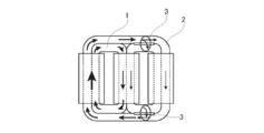
- the inner winding core 1 when the inner winding core 1 and the outer winding core 2 are excited simultaneously, the inner winding core 1 has a shorter magnetic path length than the outer winding core 2.
- the iron loss increases in the inner core 1.
- the excitation magnetic flux density is relatively small, the effect of the magnetic path length is large, so that the iron loss increase due to the concentration of magnetic flux is large.
- the inner winding core 1 alone cannot carry out excitation, and more magnetic flux passes through the outer winding core 2, so that the concentration of magnetic flux is reduced.
- the magnetic flux passing through the outer winding core 2 reaches the inner winding core 1, and an interlayer magnetic flux transfer 3 is generated between the inner winding core 1 and the outer winding core 2. It becomes like this.
- magnetization occurs in the in-plane direction, an increase in in-plane eddy current loss occurs, and a magnetic flux transition 3 between layers occurs, resulting in an increase in iron loss.
- Patent Document 3 an electromagnetic steel sheet having a magnetic property that is inferior to the outer peripheral side on the inner peripheral side with a short magnetic path length and a small magnetic resistance, and an outer peripheral side with a long magnetic path length and a large magnetic resistance on the outer peripheral side. It is disclosed that transformer iron loss is effectively reduced by arranging an electromagnetic steel sheet having excellent magnetic properties.
- Patent Document 4 a wound iron core around which a directional silicon steel sheet is wound is disposed in an inner portion, and a magnetic material having a lower magnetostriction than that of the directional silicon steel sheet is wound around the outer side of the wound core to form a combined core. It is disclosed that transformer noise can be effectively reduced.
- An object of the present invention is to provide a grain-oriented electrical steel sheet that is excellent in the effect of reducing transformer core loss when used in a wound core of a transformer. It is another object of the present invention to provide a wound core of a transformer using the grain-oriented electrical steel sheet and a method for manufacturing the same.
- the inventors of the present invention investigated the interlayer resistance between the inner winding core and the outer winding core, the magnetic resistance at the junction, and the iron loss increment in the transformer.
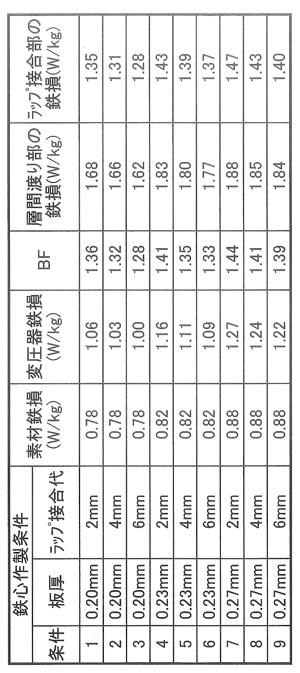
- the wound iron core of FIG. 4 has a shape of a stacking thickness: 22.5 mm, a steel plate width: 100 mm, a seven-step step lap, and a one-step lap allowance (2, 4, 6 mm).
- Non-Patent Document 1 is a document relating to the transition magnetic flux in the iron core joining wrap.
- FIG. 6 schematically shows the flow of magnetic flux at the joint estimated based on this knowledge. Assuming that there is no leakage magnetic flux outside the steel sheet, the magnetic flux reaching the joint is (A) (crossing the lap part in the out-of-plane direction), and (B) (the laminated steel sheet other than the lap part). It is divided into the inter-layer magnetic flux (crossing between layers) and the magnetic flux crossing (C) Gap (between steel plates) (in FIG.
- the magnetic flux reaching the joint (A) magnetic flux crossing + (B) inter-layer magnetic flux + (C) Gap Magnetic flux).
- the narrower the lap joint allowance the smaller the area of the lap portion, and (A) the magnetic flux crossing becomes smaller.
- the plate thickness increases, the number of stacked layers at the same stacking height in the iron core decreases, and accordingly, the area of the lap portion with respect to the joint volume decreases, so that (A) magnetic flux crossing decreases.
- the gap in the gap part depends on the accuracy of assembly, it is usually larger than the gap between the steel sheets in the stacking direction ( ⁇ the surface film thickness of the magnetic steel sheet (up to several ⁇ m)). It is considered that the magnetoresistance of (A) is larger than that of (A) magnetic flux crossover and (B) interlayer magnetic flux. Therefore, it is considered that the magnetic resistance at the junction increases as the magnetic flux density across the gap increases. And it is thought that the iron loss in a junction part became large directly because the magnetic resistance in a junction part increased.
- the magnetic resistance of the joint occupies an important factor in the increase of the iron loss at the interlayer crossing.
- the concentration of the magnetic flux in the inner core is avoided and the magnetic flux is passed through the outer core, so that the interlayer magnetic flux transfer between the inner core and the outer core increases.
- the present invention it is intended to manufacture a transformer having excellent iron loss characteristics regardless of the design of the transformer core, and after considering the influence of the plate thickness, the magnetic flux transition of the lap portion when the transformer core is formed.
- Non-Patent Document 2 Evaluation by uniaxial magnetization in the rolling direction, which is the direction of easy magnetization of the grain-oriented electrical steel sheet by the Epstein test, SST test (magnetic steel sheet single sheet magnetic property test), and a two-dimensional magnetic measurement apparatus as shown in Non-Patent Document 2 was evaluated by biaxial magnetization, and the correlation between the magnetic characteristics under various excitation conditions and the iron loss at the joint lap was investigated. Then, the iron loss deterioration rate when the elliptical magnetization defined by the following equation (1) is applied to the grain-oriented electrical steel sheet, and the wrap portion of the transformer core produced using the grain-oriented electrical steel sheet It was found that the correlation of the crossing magnetic flux density was good.
- FIG. 11 shows the result of the 0.30 mm thick material.
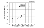
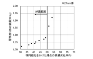
- the iron loss at the interlayer transition portion increased as the iron loss deterioration rate increased when elliptical magnetization was applied to the grain-oriented electrical steel sheet constituting the iron core.
- the magnetic flux density across the lap part or the iron loss deterioration rate when elliptical magnetization is applied is the increase in the lancet magnetic domain structure in the steel sheet, the generation of the demagnetizing field at the grain boundaries, and the heat-resistant magnetic domain due to groove formation.
- the size could be estimated by parameterizing factors such as an increase in leakage magnetic flux in the groove forming part.
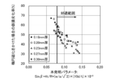
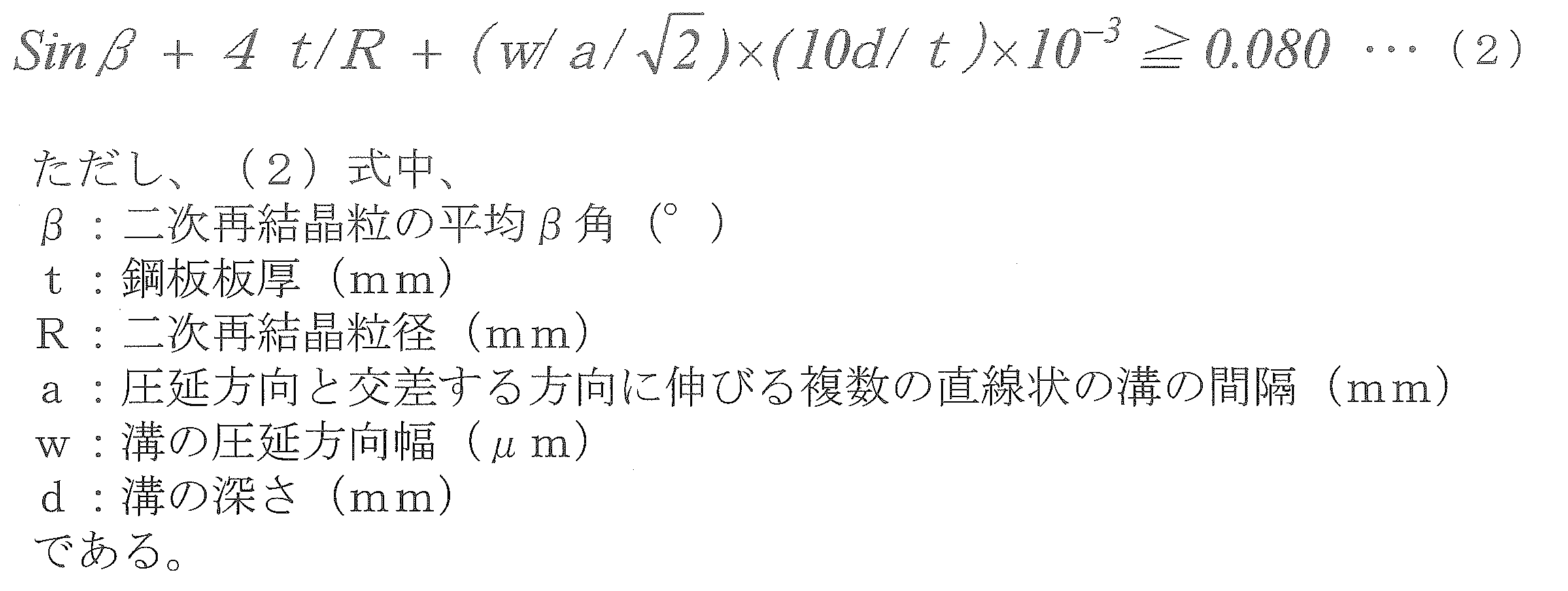
- FIG. 12 shows the relationship between the parameters of the present invention [Sin ⁇ + 4t / R + (w / a / ⁇ 2) ⁇ (10d / t) ⁇ 10 ⁇ 3 ] and the iron loss deterioration rate. As shown in FIG.
- the parameter of the present invention is 0.080 or more. It was.
- a material having a large B8 and a very high Goss orientation accumulation degree tends to have a large secondary recrystallized grain, and the secondary recrystallized grain size R may be as coarse as 40 mm or more. Then, the generation of the demagnetizing field at the crystal grain boundary is small, and the iron loss deterioration rate when the elliptical magnetization is applied as described above becomes large, and as a result, BF becomes large.
- a grain-oriented electrical steel sheet used for a wound core of a transformer A grain-oriented electrical steel sheet, characterized in that the sheet thickness t of the steel sheet and the iron loss deterioration rate when elliptical magnetization defined by the following formula (1) is applied to the steel sheet satisfy the following relationship:
- W A is the RD direction (rolling direction) 1.7 T, an iron loss in the case of applying a 50Hz ellip
- a plurality of linear grooves extending in a direction intersecting the rolling direction is formed on the steel sheet surface,
- the relationship between the rolling direction width w of the groove, the depth d of the groove, the secondary recrystallized grain size R of the steel sheet, and the average ⁇ angle of the secondary recrystallized grains of the steel sheet is as follows (2)
- [3] The grain-oriented electrical steel sheet according to [1] or [2], wherein a magnetic flux density B8 at a magnetizing force of 800 A / m is 1.91 T or more and a secondary recrystallization grain size R is 40 mm or more.
- [4] A transformer core wound using the grain-oriented electrical steel sheet according to any one of [1] to [3].
- [5] A method of manufacturing a wound core of a wound core transformer that reduces the building factor obtained by dividing the iron loss value of the wound core transformer by the iron loss value of the grain-oriented electrical steel sheet that is the material of the wound core.
- the steel sheet has a thickness t and an iron loss deterioration rate when the steel sheet is subjected to elliptical magnetization defined by the following equation (1).
- a method for manufacturing a wound core characterized by using a grain-oriented electrical steel sheet that satisfies the following relationship.
- W A is the RD direction (rolling direction) 1.7 T
- an iron loss in the case of applying a 50Hz elliptical magnetization becomes 0.6T in the TD direction (direction perpendicular to the rolling direction)
- W B is the iron loss when multiplied by the 50Hz alternating magnetization of 1.7T to the RD direction.
- a plurality of linear grooves extending in a direction intersecting the rolling direction is formed on the steel sheet surface,
- the relationship between the rolling direction width w of the groove, the depth d of the groove, the secondary recrystallized grain size R of the steel sheet, and the average ⁇ angle of the secondary recrystallized grains of the steel sheet is as follows (2)
- the grain-oriented electrical steel sheet having a magnetic flux density B8 at a magnetizing force of 800 A / m of 1.91 T or more and a secondary recrystallization grain size R of 40 mm or more is used. Method for manufacturing a wound iron core.
- the grain-oriented electrical steel sheet excellent in the reduction effect of a transformer iron loss can be provided.
- the magnetic resistance at the interlayer crossing between the inner core and the outer core and the lap joint is reduced, and the transformer core Regardless of the design, transformer iron loss in the wound core transformer can be reduced.
- a wound core transformer having a small building factor can be obtained by forming the wound core of the wound core transformer from the grain-oriented electrical steel sheet of the present invention.
- FIG. 3 is a schematic diagram showing the configuration of wound iron cores A to C produced in an example.
- the grain-oriented electrical steel sheet having excellent transformer iron loss when used in a wound transformer core must satisfy the following conditions.
- the thickness t of the grain-oriented electrical steel sheet (material) and the iron loss deterioration rate when the elliptical magnetization defined by the following formula (1) is applied to the steel sheet satisfy the following relationship.
- the plate thickness t ⁇ 0.20 mm when the iron loss deterioration rate is 60% or less 0.20 mm ⁇ plate thickness t ⁇ 0.27 mm, when the iron loss deterioration rate is 55% or less 0.27 mm ⁇ plate thickness t, Iron loss deterioration rate is 50% or less
- the iron loss in the above equation (1) is measured as follows.
- W A Iron loss when 50 Hz elliptical magnetization of 1.7 T in the RD direction and 0.6 T in the TD direction is applied
- W A is described in Non-Patent Document 2, using a two-dimensional single-plate magnetic measuring device (2D-SST), make measurements.
- a 50 Hz sine wave excitation is performed with a maximum magnetic flux density of 1.7 T in the RD direction and a maximum magnetic flux density of 0.6 T in the TD direction, and the phase difference between the RD and TD sine wave excitations is 90.
- Elliptic magnetization excitation is performed by setting to °.
- the measurement sample depends on the excitable size of the two-dimensional single-plate magnetometer, but is preferably (50 mm ⁇ 50 mm) or more in consideration of the number of crystal grains contained in one sample. In addition, taking into account variations in measurement values, it is preferable to measure and average 30 or more samples per material.
- W B Iron loss when 1.7T of 50 Hz alternating magnetization is applied in the RD direction
- W B is the same sample as the sample was measured multiplied by the elliptical magnetization described above is measured using the same measuring device.
- a maximum magnetic flux density of 1.7 T and 50 Hz sine wave excitation are performed only in the RD direction. During excitation, feedback control of the excitation voltage is performed so that the maximum magnetic flux density in the RD direction is 1.7 T, and control is not performed in the TD direction.
- a plurality of linear grooves extending in the direction intersecting the rolling direction are formed on the surface of the grain-oriented electrical steel sheet (material).
- the relationship between the rolling direction width w of the groove, the groove depth d, the secondary recrystallized grain size R of the steel sheet, and the average ⁇ angle of the secondary recrystallized grains of the steel sheet is expressed by the following equation (2): It is preferable to satisfy this relationship.
- ⁇ Average ⁇ angle of secondary recrystallized grains (°) The angle between the secondary recrystallized grains facing the rolling direction of the steel sheet and the ⁇ 100> axis rolling surface is defined as the ⁇ angle.
- the secondary recrystallization orientation of the steel sheet is measured by X-ray crystal diffraction. Since the orientation of the secondary recrystallized grains in the steel sheet varies, measurement is performed by measuring points at a pitch of 10 mm for each of RD and TD and averaging measurement area data of (500 mm ⁇ 500 mm) or more.
- R Secondary recrystallization particle size (mm)
- the film on the surface of the steel plate is removed by some chemical or electrical method, and the secondary recrystallized grain size is measured.
- the number of crystal grains having a size of about 1 mm 2 or more existing in a measurement area of (500 mm ⁇ 500 mm) or more is measured visually or by digital image processing, and the average area of one secondary recrystallized grain is obtained. From the average area, the equivalent circle diameter (diameter) is calculated to determine the secondary recrystallized grain size.
- line interval groove interval
- five points are investigated in the longitudinal direction of 500 mm, and the average is obtained. Furthermore, when the line spacing changes in the steel plate width direction, the average is taken.
- w width of groove in rolling direction ( ⁇ m)
- the surface of the steel sheet is observed with a microscope and measured. Since the rolling direction width of the groove is not always constant, five or more places are observed in a sample in the line row direction 100 mm, and the average is defined as the width of the groove in the line row. Furthermore, it is determined by observing and averaging five or more lines in a sample having a longitudinal direction of 500 mm.
- d Groove depth (mm) It measures by observing the steel plate cross section of a groove part under a microscope. Since the groove depth is not always constant, five or more locations are observed in the sample in the line row direction 100 mm, and the average is defined as the groove depth in the line row. Furthermore, it is determined by observing and averaging five or more lines in a sample having a longitudinal direction of 500 mm.
- a method for producing a grain-oriented electrical steel sheet that satisfies the above relationship will be described. Even in the methods other than those described below, the manufacturing method is not particularly limited as long as each parameter is controlled and the above expression (2) can be satisfied.
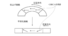
- the average ⁇ angle of the secondary recrystallized grains can be controlled by controlling the primary recrystallized structure, a coil set during finish annealing, and the like. For example, as shown in FIG. 13, when finish annealing is performed with a coil set, the ⁇ 001> direction in the crystal grains is uniform in that state. After that, when the flattening annealing is performed and the coil is in a flat state, the ⁇ 001> direction is inclined in the plate thickness direction and the ⁇ angle is increased in one crystal grain according to the coil set at the time of the final annealing. That is, the smaller the coil set, the larger the ⁇ angle of flattening annealing. If the ⁇ angle becomes too large, the magnetic flux density B8 of the material becomes small and the hysteresis loss deteriorates. Therefore, the ⁇ angle is preferably 5 ° or less.
- the secondary recrystallized grain size can be controlled by the amount of Goss orientation grains present in the primary recrystallized grains. For example, by increasing the amount of shear strain introduced before the primary recrystallized grains by increasing the final rolling reduction during cold rolling or increasing the friction during rolling, the primary recrystallized grains in the primary recrystallized grains Goss orientation grains can be increased. Moreover, the abundance of Goss orientation grains in the primary recrystallized grains can also be controlled by controlling the temperature rise rate during the primary recrystallization annealing. Since the Goss orientation grains in the primary recrystallized grains become secondary recrystallized nuclei during the final annealing, the larger the number, the more secondary recrystallized grains. As a result, the secondary recrystallized grain size becomes smaller. Become.
- Any groove forming method can be applied in the present invention.
- wear control of the gear roll is controlled, and in the groove forming method by irradiation with a high energy density laser, removal of the molten iron becomes a manufacturing issue, so electrolysis in the cold rolled sheet stage is required. It is preferable to form a groove by etching.
- a specific manufacturing method will be described by taking an example of groove formation by electrolytic etching at the cold rolled sheet stage.
- the width of the groove in the rolling direction can be controlled by controlling the width of the resist ink uncoated portion. In that case, by controlling the wetting and spreading of the resist ink and the patterning of the resist ink coating roll, it is possible to form a linear groove having a uniform groove width in the steel plate width direction.
- the depth of the groove can be controlled by subsequent electrolytic etching conditions. Specifically, the groove depth is controlled by adjusting the electrolytic etching time and current density.
- the width of the groove in the rolling direction is not particularly limited as long as the above formula (2) can be satisfied. However, if the width is too narrow, coupling of the magnetic poles occurs, and the domain subdivision effect cannot be sufficiently obtained. If it is too large, the magnetic flux density B8 of the steel sheet is decreased, so that it is preferably 40 ⁇ m or more and 250 ⁇ m or less.
- the groove depth is not particularly limited as long as the above formula (2) can be satisfied. However, if the groove depth is shallow, the magnetic domain subdivision effect cannot be sufficiently obtained. Since it decreases, it is preferably about 10 ⁇ m or more and about 1/5 or less of the plate thickness.
- interval can be controlled in a manufacturing process by any of the method quoted above. If the groove interval is too wide, the effect of subdividing the magnetic domain obtained thereby is reduced. Therefore, the groove interval is preferably 10 mm or less.
- the thickness of the grain-oriented electrical steel sheet of the present invention is not particularly limited, but is preferably 0.15 mm or more, and preferably 0.18 mm or more from the viewpoints of manufacturability, secondary recrystallization expression stability, and the like. Is more preferable. Moreover, it is preferable that it is 0.35 mm or less from points, such as eddy current loss reduction, and it is more preferable that it is 0.30 mm or less.
- the method of manufacturing the grain-oriented electrical steel sheet used for the wound core of the transformer of the present invention is not limited to the matters not directly related to the above characteristics, but the recommended preferred component composition and manufacturing other than the above-described points of the present invention are not limited. The method is described below.
- an inhibitor when used, for example, when using an AlN-based inhibitor, Al and N are contained.
- MnS / MnSe-based inhibitor an appropriate amount of Mn and Se and / or S is contained. Just do it.
- both inhibitors may be used in combination.
- preferable contents of Al, N, S and Se are respectively Al: 0.01 to 0.065 mass%, N: 0.005 to 0.012 mass%, and S: 0.005 to 0.03. Mass%, Se: 0.005 to 0.03 mass%.
- the present invention can also be applied to grain-oriented electrical steel sheets in which the content of Al, N, S, and Se is limited and no inhibitor is used.
- the amounts of Al, N, S, and Se are preferably suppressed to Al: 100 mass ppm or less, N: 50 mass ppm or less, S: 50 mass ppm or less, and Se: 50 mass ppm or less.
- Si 2.0 to 8.0 mass% Si is an element effective for increasing the electrical resistance of steel and improving iron loss. However, if the content is less than 2.0% by mass, a sufficient iron loss reducing effect cannot be achieved. If it exceeds 0.0 mass%, the workability is remarkably reduced and the magnetic flux density is also reduced. Therefore, the Si content is preferably in the range of 2.0 to 8.0 mass%.
- Mn 0.005 to 1.0 mass% Mn is an element necessary for improving the hot workability, but if the content is less than 0.005% by mass, the effect of addition is poor, whereas if it exceeds 1.0% by mass, the magnetic flux density of the product plate Therefore, the amount of Mn is preferably in the range of 0.005 to 1.0% by mass.
- the following elements can be appropriately contained as magnetic property improving components.
- Ni 0.03-1.50 mass%
- Sn 0.01-1.50 mass%
- Sb 0.005-1.50 mass%
- Cu 0.03-3.0 mass%
- P At least one selected from 0.03 to 0.50 mass%
- Mo 0.005 to 0.10 mass%
- Cr 0.03 to 1.50 mass%
- Ni is a useful element for improving the magnetic properties by improving the hot-rolled sheet structure.
- the content is less than 0.03% by mass, the effect of improving the magnetic properties is small.
- the amount of Ni is preferably in the range of 0.03 to 1.50 mass%.
- Sn, Sb, Cu, P, Cr, and Mo are elements useful for improving the magnetic properties, respectively, but if any of them does not satisfy the lower limit of each component described above, the effect of improving the magnetic properties is small. If the upper limit amount of each component described above is exceeded, the development of secondary recrystallized grains is hindered. The balance other than the above components is inevitable impurities and Fe mixed in the manufacturing process.
- the steel material adjusted to the above suitable component composition may be made into a slab by a normal ingot-making method or a continuous casting method, or a thin cast piece having a thickness of 100 mm or less may be directly produced by a continuous casting method.
- the slab is heated by a normal method and subjected to hot rolling, but may be immediately subjected to hot rolling without being heated after casting.
- hot rolling may be performed, or the hot rolling may be omitted and the subsequent process may be performed as it is.
- the final sheet thickness is obtained by one or more cold rollings sandwiching intermediate annealing, followed by decarburization annealing and final finishing annealing, and then the insulation tension Application of coating and planarization annealing.
- grooves are formed by electrolytic etching after cold rolling, or grooves are formed by applying a load with a gear roll or laser irradiation at any stage after cold rolling.
- the steel component of the product is reduced to 50 ppm or less by decarburization annealing, and further, Al, N, S, and Se are reduced to inevitable impurity levels by purification by finish annealing.
- a wound core transformer having other joint structure such as a three-phase pentapod or a single-phase excitation type, is described. It is also suitable when used for an iron core.
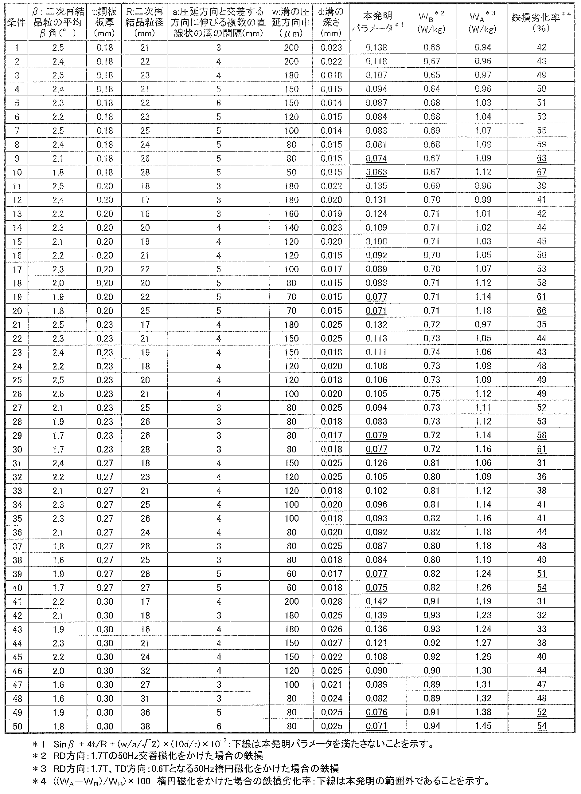
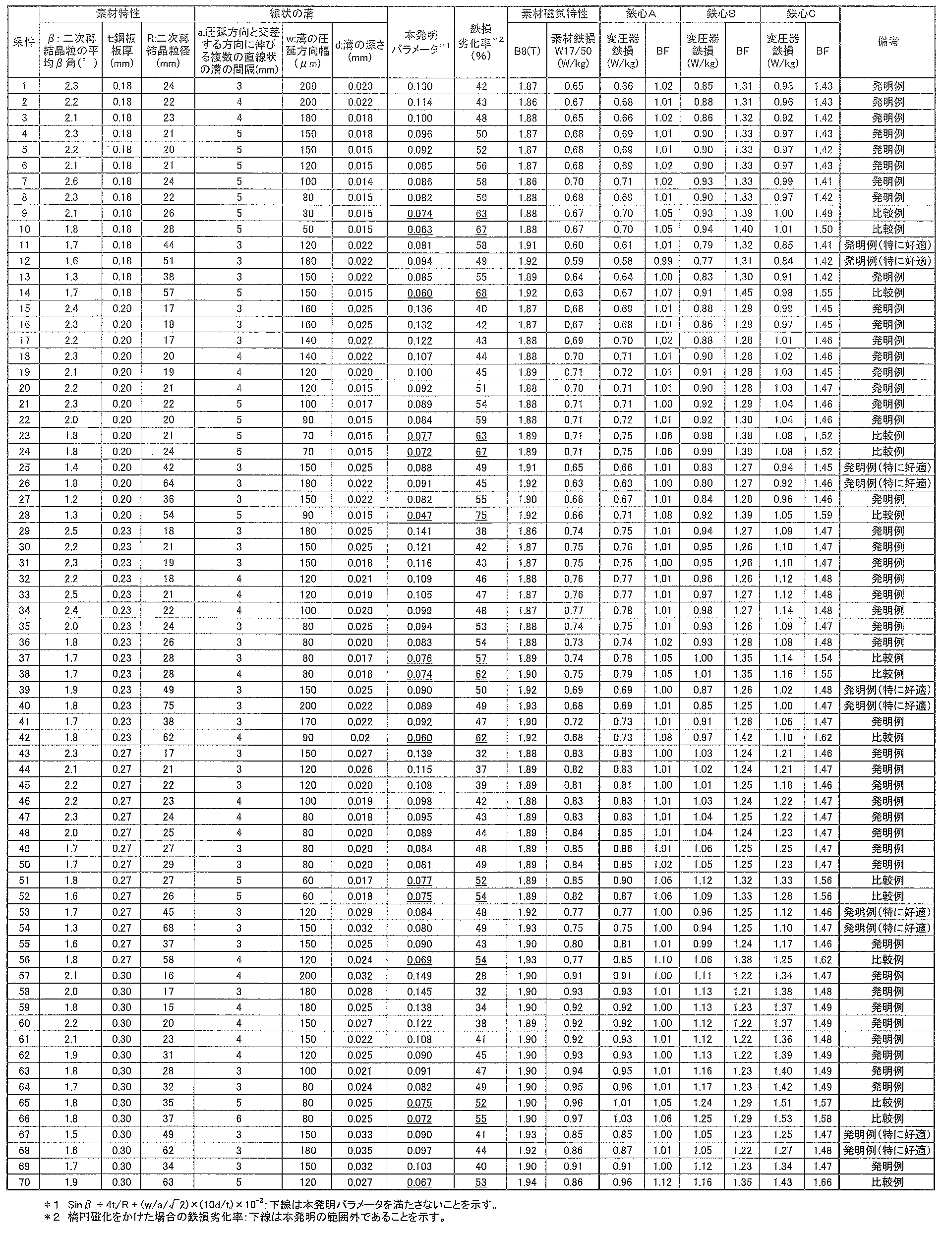
- a grain-oriented electrical steel sheet having a cold finish thickness of 0.18 to 0.30 mm was produced by changing the rolling reduction and the temperature increase rate of primary recrystallization annealing. At that time, grooves were formed by electrolytic etching under various conditions after cold rolling, and the grain-oriented electrical steel sheets having the material characteristics shown in Table 3 were obtained.
- the electromagnetic steel sheet was subjected to two-dimensional magnetic measurement by the method described in this specification, and the iron loss deterioration rate was measured when elliptical magnetization was applied. For each material, core-shaped transformer-wound iron cores A to C shown in FIG.
- the wound iron core A shown in FIG. 14 has a stacking thickness of 22.5 mm, a steel plate width of 100 mm, a seven-step step wrap, a one-step wrap margin of 8 mm, and the wound iron core B has a stacking thickness of 20 mm, a steel plate width of 100 mm, and seven steps.
- the step wrap, one-step lap margin: 5 mm, and the wound iron core C have a shape of stacking thickness: 30 mm, steel plate width: 120 mm, seven-step step wrap, one-step lap margin: 8 mm.
- the BF was smaller than that of the comparative example in any iron core shape.
- a grain-oriented electrical steel sheet having a magnetic flux density B8 ⁇ 1.91T at a magnetizing force of 800 A / m and a secondary recrystallized grain size R ⁇ 40 mm is used, the material iron loss is small and the BF is small. The iron loss in the vessel was very small.
Landscapes
- Engineering & Computer Science (AREA)
- Power Engineering (AREA)
- Chemical & Material Sciences (AREA)
- Physics & Mathematics (AREA)
- Manufacturing & Machinery (AREA)
- Electromagnetism (AREA)
- Dispersion Chemistry (AREA)
- Organic Chemistry (AREA)
- Mechanical Engineering (AREA)
- Materials Engineering (AREA)
- Metallurgy (AREA)
- Crystallography & Structural Chemistry (AREA)
- Thermal Sciences (AREA)
- Soft Magnetic Materials (AREA)
- Manufacturing Of Steel Electrode Plates (AREA)
- Manufacturing Cores, Coils, And Magnets (AREA)
Abstract
Description
ただし、(1)式中、WAは、RD方向(圧延方向)に1.7T、TD方向(圧延方向に直角な方向)に0.6Tとなる50Hz楕円磁化をかけた場合の鉄損であり、WBは、RD方向に1.7Tの50Hz交番磁化をかけた場合の鉄損である。
β:二次再結晶粒の平均β角(°)
二次再結晶粒の平均β角が大きくなると、Sinβに比例して静磁エネルギーが増加し、それを緩和しようとランセット磁区量が増加すると考えられる。
t:鋼板板厚(mm)
R:二次再結晶粒径(mm)
鋼板面単位面積当たりの粒界面積割合4t/Rに応じて、粒界に生じる反磁界は大きくなると考えられる。
a:圧延方向と交差する方向に伸びる複数の直線状の溝の間隔(mm)
w:溝の圧延方向幅(μm)
d:溝の深さ(mm)
鋼板面単位面積当たり溝形成部の面積は(w/a)×10-3となる。さらに板厚に対する溝深さd/tに応じて、漏れ磁束は大きくなると考える。
[1]変圧器の巻鉄心に用いる方向性電磁鋼板であって、
該鋼板の板厚tと、該鋼板に下記(1)式で定義される楕円磁化をかけた場合の鉄損劣化率が、以下の関係を満たすことを特徴とする方向性電磁鋼板。
板厚t≦0.20mmの場合、鉄損劣化率が60%以下
0.20mm<板厚t<0.27mmの場合、鉄損劣化率が55%以下
0.27mm≦板厚tの場合、鉄損劣化率が50%以下
(楕円磁化をかけた場合の鉄損劣化率)=((WA-WB)/WB)×100 ・・・(1)
ただし、(1)式中、WAは、RD方向(圧延方向)に1.7T、TD方向(圧延方向に直角な方向)に0.6Tとなる50Hz楕円磁化をかけた場合の鉄損であり、WBは、RD方向に1.7Tの50Hz交番磁化をかけた場合の鉄損である。
[2]該鋼板表面に、圧延方向と交差する方向に伸びる複数の直線状の溝が形成され、
前記溝の圧延方向幅wと、前記溝の深さdと、該鋼板の二次再結晶粒径Rと、該鋼板の二次再結晶粒の平均β角との関係が、下記(2)式の関係を満たすことを特徴とする、[1]に記載の方向性電磁鋼板。

[3]磁化力800A/mにおける磁束密度B8が1.91T以上であり、かつ、二次再結晶粒径Rが40mm以上である、[1]または[2]に記載の方向性電磁鋼板。
[4]上記[1]~[3]のいずれかに記載の方向性電磁鋼板を用いてなることを特徴とする変圧器の巻鉄心。
[5]巻鉄心変圧器の鉄損値を、該巻鉄心の素材である方向性電磁鋼板の鉄損値で除して求められるビルディングファクタを小さくする巻鉄心変圧器の巻鉄心の製造方法であって、
方向性電磁鋼板を巻き重ねて巻鉄心とする際に、該鋼板として、該鋼板の板厚tと該鋼板に下記(1)式で定義される楕円磁化をかけた場合の鉄損劣化率が、以下の関係を満たす方向性電磁鋼板を用いることを特徴とする巻鉄心の製造方法。
板厚t≦0.20mmの場合、鉄損劣化率が60%以下
0.20mm<板厚t<0.27mmの場合、鉄損劣化率が55%以下
0.27mm≦板厚tの場合、鉄損劣化率が50%以下
(楕円磁化をかけた場合の鉄損劣化率)=((WA-WB)/WB)×100 ・・・(1)
ただし、(1)式中、WAは、RD方向(圧延方向)に1.7T、TD方向(圧延方向に直角な方向)に0.6Tとなる50Hz楕円磁化をかけた場合の鉄損であり、WBは、RD方向に1.7Tの50Hz交番磁化をかけた場合の鉄損である。
[6]該鋼板表面に、圧延方向と交差する方向に伸びる複数の直線状の溝が形成され、
前記溝の圧延方向幅wと、前記溝の深さdと、該鋼板の二次再結晶粒径Rと、該鋼板の二次再結晶粒の平均β角との関係が、下記(2)式の関係を満たすことを特徴とする、[5]に記載の巻鉄心の製造方法。
[7]磁化力800A/mにおける磁束密度B8が1.91T以上であり、かつ、二次再結晶粒径Rが40mm以上である方向性電磁鋼板を用いる、[5]または[6]に記載の巻鉄心の製造方法。
本発明によれば、変圧器鉄心として用いられる方向性電磁鋼板の特性を制御することで、内巻コアと外巻コアの間の層間渡り及びラップ接合部における磁気抵抗を低減し、変圧器鉄心の設計に関わらず、巻鉄心変圧器における変圧器鉄損を低減することができる。
本発明によれば、巻鉄心変圧器の巻鉄心を本発明の方向性電磁鋼板を素材として構成することで、ビルディングファクタの小さい巻鉄心変圧器が得られる。
板厚t≦0.20mmの場合、鉄損劣化率が60%以下
0.20mm<板厚t<0.27mmの場合、鉄損劣化率が55%以下
0.27mm≦板厚tの場合、鉄損劣化率が50%以下
ただし、(1)式中、WAは、RD方向(圧延方向)に1.7T、TD方向(圧延方向に直角な方向)に0.6Tとなる50Hz楕円磁化をかけた場合の鉄損であり、WBは、RD方向に1.7Tの50Hz交番磁化をかけた場合の鉄損である。
WAは、非特許文献2などに記載がある、二次元単板磁気測定装置(2D-SST)を用いて、測定を行う。方向性電磁鋼板(素材)のRD方向に最大磁束密度1.7T、TD方向に最大磁束密度0.6Tとなる50Hz正弦波励磁を行い、RD方向とTD方向の正弦波励磁の位相差を90°とすることで楕円磁化励磁を行う。この際、楕円磁化の回転方向は、時計回りと反時計回りがあるが、両者における鉄損測定値には差があることが指摘されており、両者の測定を実施したうえで平均値をとる。鉄損測定方法は探針法、Hコイル法など種々の方法が提案されているが、いずれの方法を用いても良い。また励磁に際しては、RD方向は最大磁束密度1.7T、TD方向は最大磁束密度0.6Tとなるよう、励磁電圧のフィードバック制御を行うが、磁束密度が最大となる瞬間以外は磁束波形が正弦波より若干歪む場合でも、波形制御は行わない。測定試料は二次元単板磁気測定装置の励磁可能サイズによるが、1試料に含まれる結晶粒の数を考慮して、(50mm×50mm)以上が好ましい。また、測定値のバラつきを考慮し、1素材につき30枚以上の試料を測定し平均することが好ましい。
WBは、上記の楕円磁化をかけた測定を行った試料と同じ試料を、同じ測定装置を使って測定する。RD方向のみに最大磁束密度1.7T、50Hz正弦波励磁を行う。励磁に際しては、RD方向最大磁束密度1.7Tとなるような、励磁電圧のフィードバック制御を行い、TD方向には制御を行わない。

鋼板の圧延方向を向く二次再結晶粒の〈100〉軸の圧延面となす角をβ角と定義される。鋼板の二次再結晶方位をX線結晶回折にて測定する。鋼板内の二次再結晶粒の方位にはバラつきがあるので、RD、TDそれぞれ10mmピッチのポイントで測定し、(500mm×500mm)以上の測定領域データを平均することで求める。
鋼板表面上の被膜をなんらかの化学的、電気的手法で除去し、二次再結晶粒径を測定する。(500mm×500mm)以上の測定領域に存在する、1mm2程度以上の大きさの結晶粒個数を目視、あるいはデジタル画像処理により測定し、二次再結晶粒1個の平均面積を求める。その平均面積より、円相当径(直径)を計算し、二次再結晶粒径を求める。
直線状の溝同士のRD方向の間隔で定義する。線間隔(溝の間隔)が一定でない場合には、長手方向500mmで5箇所を調査し、その平均とする。さらに、鋼板幅方向で線間隔が変わる場合には、その平均とする。
鋼板表面を顕微鏡観察し測定する。溝の圧延方向幅は必ずしも一定とは限らないので、線列方向100mm試料内において5箇所以上を観察し、平均をその線列における溝の圧延方向幅とする。さらに、長手方向500mmの試料内において線列5箇所以上を観察し、平均し求めることとする。
溝部の鋼板断面を顕微鏡観察することで測定する。溝の深さは必ずしも一定とは限らないので、線列方向100mm試料内において5箇所以上を観察し、平均をその線列における溝の深さとする。さらに、長手方向500mmの試料内において線列5箇所以上を観察し、平均し求めることとする。
C量が0.08質量%を超えると製造工程中に磁気時効の起こらない50質量ppm以下までCを低減することが困難になるため、0.08質量%以下とすることが好ましい。なお、下限に関しては、Cを含まない素材でも二次再結晶が可能であるので特に設ける必要はない。
Siは、鋼の電気抵抗を高め、鉄損を改善するのに有効な元素であるが、含有量が2.0質量%に満たないと十分な鉄損低減効果が達成できず、一方、8.0質量%を超えると加工性が著しく低下し、また磁束密度も低下するため、Si量は2.0~8.0質量%の範囲とすることが好ましい。
Mnは、熱間加工性を良好にする上で必要な元素であるが、含有量が0.005質量%未満ではその添加効果に乏しく、一方1.0質量%を超えると製品板の磁束密度が低下するため、Mn量は0.005~1.0質量%の範囲とすることが好ましい。
Claims (7)
- 変圧器の巻鉄心に用いる方向性電磁鋼板であって、
該鋼板の板厚tと、該鋼板に下記(1)式で定義される楕円磁化をかけた場合の鉄損劣化率が、以下の関係を満たす方向性電磁鋼板。
板厚t≦0.20mmの場合、鉄損劣化率が60%以下
0.20mm<板厚t<0.27mmの場合、鉄損劣化率が55%以下
0.27mm≦板厚tの場合、鉄損劣化率が50%以下
(楕円磁化をかけた場合の鉄損劣化率)=((WA-WB)/WB)×100 ・・・(1)
ただし、(1)式中、WAは、RD方向(圧延方向)に1.7T、TD方向(圧延方向に直角な方向)に0.6Tとなる50Hz楕円磁化をかけた場合の鉄損であり、WBは、RD方向に1.7Tの50Hz交番磁化をかけた場合の鉄損である。 - 該鋼板表面に、圧延方向と交差する方向に伸びる複数の直線状の溝が形成され、
前記溝の圧延方向幅wと、前記溝の深さdと、該鋼板の二次再結晶粒径Rと、該鋼板の二次再結晶粒の平均β角との関係が、下記(2)式の関係を満たす、請求項1に記載の方向性電磁鋼板。

- 磁化力800A/mにおける磁束密度B8が1.91T以上であり、かつ、二次再結晶粒径Rが40mm以上である、請求項1または2に記載の方向性電磁鋼板。
- 請求項1~3のいずれかに記載の方向性電磁鋼板を用いてなる変圧器の巻鉄心。
- 巻鉄心変圧器の鉄損値を、該巻鉄心の素材である方向性電磁鋼板の鉄損値で除して求められるビルディングファクタを小さくする巻鉄心変圧器の巻鉄心の製造方法であって、
方向性電磁鋼板を巻き重ねて巻鉄心とする際に、該鋼板として、該鋼板の板厚tと該鋼板に下記(1)式で定義される楕円磁化をかけた場合の鉄損劣化率が、以下の関係を満たす方向性電磁鋼板を用いる巻鉄心の製造方法。
板厚t≦0.20mmの場合、鉄損劣化率が60%以下
0.20mm<板厚t<0.27mmの場合、鉄損劣化率が55%以下
0.27mm≦板厚tの場合、鉄損劣化率が50%以下
(楕円磁化をかけた場合の鉄損劣化率)=((WA-WB)/WB)×100 ・・・(1)
ただし、(1)式中、WAは、RD方向(圧延方向)に1.7T、TD方向(圧延方向に直角な方向)に0.6Tとなる50Hz楕円磁化をかけた場合の鉄損であり、WBは、RD方向に1.7Tの50Hz交番磁化をかけた場合の鉄損である。 - 該鋼板表面に、圧延方向と交差する方向に伸びる複数の直線状の溝が形成され、
前記溝の圧延方向幅wと、前記溝の深さdと、該鋼板の二次再結晶粒径Rと、該鋼板の二次再結晶粒の平均β角との関係が、下記(2)式の関係を満たす、請求項5に記載の巻鉄心の製造方法。

- 磁化力800A/mにおける磁束密度B8が1.91T以上であり、かつ、二次再結晶粒径Rが40mm以上である方向性電磁鋼板を用いる、請求項5または6に記載の巻鉄心の製造方法。
Priority Applications (8)
| Application Number | Priority Date | Filing Date | Title |
|---|---|---|---|
| EP19747292.1A EP3726543A4 (en) | 2018-01-31 | 2019-01-31 | DIRECTIONAL ELECTRIC STEEL SHEET, USING WIRED TRANSFORMER CORE, AND WIRE CORE MANUFACTURING PROCESS |
| US16/966,256 US11984249B2 (en) | 2018-01-31 | 2019-01-31 | Grain-oriented electrical steel sheet, wound transformer core using the same, and method for producing wound core |
| CA3086308A CA3086308C (en) | 2018-01-31 | 2019-01-31 | Grain-oriented electrical steel sheet, wound transformer core using the same, and method for producing wound core |
| CN201980010739.1A CN111656465B (zh) | 2018-01-31 | 2019-01-31 | 方向性电磁钢板、使用该方向性电磁钢板而成的变压器的卷绕铁芯和卷绕铁芯的制造方法 |
| JP2019521158A JP7028242B2 (ja) | 2018-01-31 | 2019-01-31 | 方向性電磁鋼板およびこれを用いてなる変圧器の巻鉄心並びに巻鉄心の製造方法 |
| RU2020125346A RU2741403C1 (ru) | 2018-01-31 | 2019-01-31 | Текстурированный лист из электротехнической стали, ленточный сердечник трансформатора из текстурированного листа из электротехнической стали и способ изготовления ленточного сердечника |
| KR1020207022134A KR102360385B1 (ko) | 2018-01-31 | 2019-01-31 | 방향성 전자 강판 및 이것을 이용하여 이루어지는 변압기의 권철심과 권철심의 제조 방법 |
| MX2020007993A MX2020007993A (es) | 2018-01-31 | 2019-01-31 | Chapa de acero electrico de grano orientado, nucleo enrollado de transformador que usa la misma y metodo para producir el nucleo enrollado. |
Applications Claiming Priority (2)
| Application Number | Priority Date | Filing Date | Title |
|---|---|---|---|
| JP2018-014244 | 2018-01-31 | ||
| JP2018014244 | 2018-01-31 |
Publications (1)
| Publication Number | Publication Date |
|---|---|
| WO2019151399A1 true WO2019151399A1 (ja) | 2019-08-08 |
Family
ID=67479262
Family Applications (1)
| Application Number | Title | Priority Date | Filing Date |
|---|---|---|---|
| PCT/JP2019/003399 Ceased WO2019151399A1 (ja) | 2018-01-31 | 2019-01-31 | 方向性電磁鋼板およびこれを用いてなる変圧器の巻鉄心並びに巻鉄心の製造方法 |
Country Status (9)
| Country | Link |
|---|---|
| US (1) | US11984249B2 (ja) |
| EP (1) | EP3726543A4 (ja) |
| JP (1) | JP7028242B2 (ja) |
| KR (1) | KR102360385B1 (ja) |
| CN (1) | CN111656465B (ja) |
| CA (1) | CA3086308C (ja) |
| MX (1) | MX2020007993A (ja) |
| RU (1) | RU2741403C1 (ja) |
| WO (1) | WO2019151399A1 (ja) |
Cited By (10)
| Publication number | Priority date | Publication date | Assignee | Title |
|---|---|---|---|---|
| CN111931310A (zh) * | 2020-08-28 | 2020-11-13 | 西南交通大学 | 一种考虑相异磁场边界条件的卷铁心层间短路涡流损耗评估方法 |
| WO2021250953A1 (ja) * | 2020-06-09 | 2021-12-16 | Jfeスチール株式会社 | 方向性電磁鋼板 |
| JP7056717B1 (ja) | 2020-11-13 | 2022-04-19 | Jfeスチール株式会社 | 巻鉄心 |
| JPWO2022092114A1 (ja) * | 2020-10-26 | 2022-05-05 | ||
| JPWO2023234013A1 (ja) * | 2022-05-30 | 2023-12-07 | ||
| JP2024001799A (ja) * | 2022-06-22 | 2024-01-10 | Jfeスチール株式会社 | ステータ及びモータ |
| RU2811454C1 (ru) * | 2020-10-26 | 2024-01-11 | Ниппон Стил Корпорейшн | Ленточный сердечник |
| JP2024013843A (ja) * | 2022-07-21 | 2024-02-01 | Jfeスチール株式会社 | 三相三脚巻鉄心およびこれを用いた三相三脚巻鉄心変圧器 |
| JPWO2025070795A1 (ja) * | 2023-09-27 | 2025-04-03 | ||
| JP2025076669A (ja) * | 2023-11-02 | 2025-05-16 | 株式会社日立産機システム | 静止誘導機器 |
Families Citing this family (3)
| Publication number | Priority date | Publication date | Assignee | Title |
|---|---|---|---|---|
| US11495378B2 (en) * | 2018-01-31 | 2022-11-08 | Jfe Steel Corporation | Grain-oriented electrical steel sheet, stacked transformer core using the same, and method for producing stacked core |
| WO2022092120A1 (ja) * | 2020-10-26 | 2022-05-05 | 日本製鉄株式会社 | 巻鉄心 |
| KR102849731B1 (ko) * | 2021-07-30 | 2025-08-22 | 제이에프이 스틸 가부시키가이샤 | 권철심 및 권철심의 제조 방법 |
Citations (10)
| Publication number | Priority date | Publication date | Assignee | Title |
|---|---|---|---|---|
| JPS5750820B2 (ja) | 1975-09-30 | 1982-10-29 | ||
| JPS6253579B2 (ja) | 1984-11-10 | 1987-11-11 | Nippon Steel Corp | |
| JPH0369968B2 (ja) | 1983-04-20 | 1991-11-06 | Kawasaki Steel Co | |
| JPH03268311A (ja) | 1990-03-19 | 1991-11-29 | Toshiba Corp | 変圧器鉄心 |
| JPH06100997A (ja) * | 1992-09-21 | 1994-04-12 | Nippon Steel Corp | グラス被膜を有しない磁気特性の優れた珪素鋼板及びその製造法 |
| JPH06136552A (ja) * | 1992-10-22 | 1994-05-17 | Nippon Steel Corp | 磁気鉄損の優れた方向性電磁鋼板およびその製造法 |
| JPH06220541A (ja) * | 1993-01-27 | 1994-08-09 | Nippon Steel Corp | 磁気鉄損の優れた高磁束密度方向性珪素鋼板およびその製造法 |
| JP2005240079A (ja) * | 2004-02-25 | 2005-09-08 | Jfe Steel Kk | 鉄損劣化率が小さい方向性電磁鋼板 |
| JP2012126973A (ja) * | 2010-12-16 | 2012-07-05 | Jfe Steel Corp | 方向性電磁鋼板およびその製造方法 |
| JP5286292B2 (ja) | 2005-07-08 | 2013-09-11 | 株式会社日立産機システム | 静止機器用巻鉄心、及び三相三脚巻鉄心 |
Family Cites Families (18)
| Publication number | Priority date | Publication date | Assignee | Title |
|---|---|---|---|---|
| JPS6253579A (ja) | 1985-09-03 | 1987-03-09 | Seiko Epson Corp | 携帯用受信機器 |
| JPH0369968A (ja) | 1989-08-09 | 1991-03-26 | Canon Inc | 複写装置 |
| US5507883A (en) * | 1992-06-26 | 1996-04-16 | Nippon Steel Corporation | Grain oriented electrical steel sheet having high magnetic flux density and ultra low iron loss and process for production the same |
| KR960009170B1 (en) | 1992-07-02 | 1996-07-16 | Nippon Steel Corp | Grain oriented electrical steel sheet having high magnetic flux density and ultra iron loss and process for producing the same |
| KR960010595B1 (ko) | 1992-09-21 | 1996-08-06 | 신니뽄세이데스 가부시끼가이샤 | 1차 막이 최소화되고 자성이 뛰어나며 운용성이 우수한 배향 전기 강판의 제조방법 |
| EP0892072B1 (en) * | 1997-07-17 | 2003-01-22 | Kawasaki Steel Corporation | Grain-oriented electrical steel sheet excellent in magnetic characteristics and production process for same |
| JP4823719B2 (ja) | 2006-03-07 | 2011-11-24 | 新日本製鐵株式会社 | 磁気特性が極めて優れた方向性電磁鋼板の製造方法 |
| JP5750820B2 (ja) | 2009-09-29 | 2015-07-22 | Jfeスチール株式会社 | 鉄損測定方法 |
| JP5754097B2 (ja) * | 2010-08-06 | 2015-07-22 | Jfeスチール株式会社 | 方向性電磁鋼板およびその製造方法 |
| BR112013005450B1 (pt) * | 2010-09-10 | 2019-05-07 | Jfe Steel Corporation | Chapa de aço elétrico com grão orientado e método para produção da mesma. |
| US10020101B2 (en) | 2011-12-22 | 2018-07-10 | Jfe Steel Corporation | Grain-oriented electrical steel sheet and method for producing same |
| JP6007501B2 (ja) * | 2012-02-08 | 2016-10-12 | Jfeスチール株式会社 | 方向性電磁鋼板 |
| US10629346B2 (en) * | 2012-04-26 | 2020-04-21 | Jfe Steel Corporation | Method of manufacturing grain-oriented electrical steel sheet |
| IN2014MN01807A (ja) | 2012-04-26 | 2015-07-03 | Jfe Steel Corp | |
| US10131018B2 (en) | 2012-04-27 | 2018-11-20 | Nippon Steel & Sumitomo Metal Corporation | Grain-oriented magnetic steel sheet and method of producing the same |
| WO2016056501A1 (ja) | 2014-10-06 | 2016-04-14 | Jfeスチール株式会社 | 低鉄損方向性電磁鋼板およびその製造方法 |
| US11495378B2 (en) * | 2018-01-31 | 2022-11-08 | Jfe Steel Corporation | Grain-oriented electrical steel sheet, stacked transformer core using the same, and method for producing stacked core |
| JP6947248B1 (ja) * | 2020-06-09 | 2021-10-13 | Jfeスチール株式会社 | 方向性電磁鋼板 |
-
2019
- 2019-01-31 CN CN201980010739.1A patent/CN111656465B/zh active Active
- 2019-01-31 WO PCT/JP2019/003399 patent/WO2019151399A1/ja not_active Ceased
- 2019-01-31 KR KR1020207022134A patent/KR102360385B1/ko active Active
- 2019-01-31 RU RU2020125346A patent/RU2741403C1/ru active
- 2019-01-31 EP EP19747292.1A patent/EP3726543A4/en not_active Ceased
- 2019-01-31 JP JP2019521158A patent/JP7028242B2/ja active Active
- 2019-01-31 CA CA3086308A patent/CA3086308C/en active Active
- 2019-01-31 US US16/966,256 patent/US11984249B2/en active Active
- 2019-01-31 MX MX2020007993A patent/MX2020007993A/es unknown
Patent Citations (10)
| Publication number | Priority date | Publication date | Assignee | Title |
|---|---|---|---|---|
| JPS5750820B2 (ja) | 1975-09-30 | 1982-10-29 | ||
| JPH0369968B2 (ja) | 1983-04-20 | 1991-11-06 | Kawasaki Steel Co | |
| JPS6253579B2 (ja) | 1984-11-10 | 1987-11-11 | Nippon Steel Corp | |
| JPH03268311A (ja) | 1990-03-19 | 1991-11-29 | Toshiba Corp | 変圧器鉄心 |
| JPH06100997A (ja) * | 1992-09-21 | 1994-04-12 | Nippon Steel Corp | グラス被膜を有しない磁気特性の優れた珪素鋼板及びその製造法 |
| JPH06136552A (ja) * | 1992-10-22 | 1994-05-17 | Nippon Steel Corp | 磁気鉄損の優れた方向性電磁鋼板およびその製造法 |
| JPH06220541A (ja) * | 1993-01-27 | 1994-08-09 | Nippon Steel Corp | 磁気鉄損の優れた高磁束密度方向性珪素鋼板およびその製造法 |
| JP2005240079A (ja) * | 2004-02-25 | 2005-09-08 | Jfe Steel Kk | 鉄損劣化率が小さい方向性電磁鋼板 |
| JP5286292B2 (ja) | 2005-07-08 | 2013-09-11 | 株式会社日立産機システム | 静止機器用巻鉄心、及び三相三脚巻鉄心 |
| JP2012126973A (ja) * | 2010-12-16 | 2012-07-05 | Jfe Steel Corp | 方向性電磁鋼板およびその製造方法 |
Non-Patent Citations (3)
| Title |
|---|
| See also references of EP3726543A4 |
| THE PAPERS OF TECHNICAL MEETING ON MAGNETICS, INSTITUTE OF ELECTRICAL ENGINEERS OF JAPAN, 2004, pages 27 - 31 |
| THE TRANSACTIONS OF THE INSTITUTE OF ELECTRICAL ENGINEERS OF JAPAN. D, vol. 130, no. 9, 2010, pages 1087 - 1093 |
Cited By (24)
| Publication number | Priority date | Publication date | Assignee | Title |
|---|---|---|---|---|
| WO2021250953A1 (ja) * | 2020-06-09 | 2021-12-16 | Jfeスチール株式会社 | 方向性電磁鋼板 |
| JP2021195571A (ja) * | 2020-06-09 | 2021-12-27 | Jfeスチール株式会社 | 方向性電磁鋼板 |
| US11990261B2 (en) | 2020-06-09 | 2024-05-21 | Jfe Steel Corporation | Grain-oriented electrical steel sheet |
| CN111931310A (zh) * | 2020-08-28 | 2020-11-13 | 西南交通大学 | 一种考虑相异磁场边界条件的卷铁心层间短路涡流损耗评估方法 |
| RU2811454C1 (ru) * | 2020-10-26 | 2024-01-11 | Ниппон Стил Корпорейшн | Ленточный сердечник |
| KR102877444B1 (ko) | 2020-10-26 | 2025-10-29 | 닛폰세이테츠 가부시키가이샤 | 권철심 |
| JPWO2022092114A1 (ja) * | 2020-10-26 | 2022-05-05 | ||
| WO2022092114A1 (ja) * | 2020-10-26 | 2022-05-05 | 日本製鉄株式会社 | 巻鉄心 |
| JP7538440B2 (ja) | 2020-10-26 | 2024-08-22 | 日本製鉄株式会社 | 巻鉄心 |
| KR20230070021A (ko) * | 2020-10-26 | 2023-05-19 | 닛폰세이테츠 가부시키가이샤 | 권철심 |
| WO2022102224A1 (ja) * | 2020-11-13 | 2022-05-19 | Jfeスチール株式会社 | 巻鉄心 |
| JP7056717B1 (ja) | 2020-11-13 | 2022-04-19 | Jfeスチール株式会社 | 巻鉄心 |
| JP2022078444A (ja) * | 2020-11-13 | 2022-05-25 | Jfeスチール株式会社 | 巻鉄心 |
| WO2023234013A1 (ja) * | 2022-05-30 | 2023-12-07 | Jfeスチール株式会社 | データセット生成方法、電磁界解析方法及びコンピュータプログラム |
| JPWO2023234013A1 (ja) * | 2022-05-30 | 2023-12-07 | ||
| JP7632666B2 (ja) | 2022-05-30 | 2025-02-19 | Jfeスチール株式会社 | データセット生成方法、電磁界解析方法及びコンピュータプログラム |
| JP7718334B2 (ja) | 2022-06-22 | 2025-08-05 | Jfeスチール株式会社 | ステータ及びモータ |
| JP2024001799A (ja) * | 2022-06-22 | 2024-01-10 | Jfeスチール株式会社 | ステータ及びモータ |
| JP7632411B2 (ja) | 2022-07-21 | 2025-02-19 | Jfeスチール株式会社 | 三相三脚巻鉄心およびこれを用いた三相三脚巻鉄心変圧器 |
| JP2024013843A (ja) * | 2022-07-21 | 2024-02-01 | Jfeスチール株式会社 | 三相三脚巻鉄心およびこれを用いた三相三脚巻鉄心変圧器 |
| WO2025070795A1 (ja) * | 2023-09-27 | 2025-04-03 | 日本製鉄株式会社 | 方向性電磁鋼板及びその製造方法 |
| JPWO2025070795A1 (ja) * | 2023-09-27 | 2025-04-03 | ||
| JP7836023B2 (ja) | 2023-09-27 | 2026-03-26 | 日本製鉄株式会社 | 方向性電磁鋼板及びその製造方法 |
| JP2025076669A (ja) * | 2023-11-02 | 2025-05-16 | 株式会社日立産機システム | 静止誘導機器 |
Also Published As
| Publication number | Publication date |
|---|---|
| US11984249B2 (en) | 2024-05-14 |
| MX2020007993A (es) | 2020-09-09 |
| JPWO2019151399A1 (ja) | 2020-12-03 |
| KR102360385B1 (ko) | 2022-02-08 |
| CN111656465B (zh) | 2022-12-27 |
| CN111656465A (zh) | 2020-09-11 |
| CA3086308C (en) | 2023-06-20 |
| EP3726543A4 (en) | 2021-03-03 |
| RU2741403C1 (ru) | 2021-01-25 |
| KR20200103090A (ko) | 2020-09-01 |
| EP3726543A1 (en) | 2020-10-21 |
| US20210043358A1 (en) | 2021-02-11 |
| CA3086308A1 (en) | 2019-08-08 |
| JP7028242B2 (ja) | 2022-03-02 |
Similar Documents
| Publication | Publication Date | Title |
|---|---|---|
| JP7028242B2 (ja) | 方向性電磁鋼板およびこれを用いてなる変圧器の巻鉄心並びに巻鉄心の製造方法 | |
| JP7028244B2 (ja) | 方向性電磁鋼板およびこれを用いてなる変圧器の積鉄心並びに積鉄心の製造方法 | |
| KR101607909B1 (ko) | 방향성 전자 강판 및 그것을 이용한 변압기 철심 | |
| WO2012017670A1 (ja) | 方向性電磁鋼板およびその製造方法 | |
| JP2007314826A (ja) | 鉄損特性に優れた一方向性電磁鋼板 | |
| JP7485954B2 (ja) | 巻鉄心 | |
| JP4192399B2 (ja) | 方向性電磁鋼板およびその製造方法 | |
| JP2000345306A (ja) | 高磁場鉄損の優れた高磁束密度一方向性電磁鋼板 | |
| JP2012057232A (ja) | 方向性電磁鋼板およびその製造方法 | |
| JP5565307B2 (ja) | 方向性電磁鋼板の製造方法 | |
| JP7188662B2 (ja) | 巻鉄心 | |
| JP6947248B1 (ja) | 方向性電磁鋼板 | |
| KR102484304B1 (ko) | 자기 특성이 우수한 방향성 전자기 강판 | |
| JP7648871B2 (ja) | 巻鉄心 | |
| JP7318845B1 (ja) | 三相三脚巻鉄心およびその製造方法 | |
| JP4276618B2 (ja) | 低鉄損一方向性電磁鋼板 | |
| JP5742175B2 (ja) | 低鉄損三相積変圧器 | |
| KR20250141824A (ko) | 변압기용 철심 및 변압기 | |
| CA3289769A1 (en) | Iron core for transformer and transformer | |
| WO2025022804A1 (ja) | 変圧器用鉄心および変圧器 | |
| WO2023167016A1 (ja) | 三相三脚巻鉄心およびその製造方法 | |
| JPS61294804A (ja) | 低鉄損一方向性けい素鋼板の製法 |
Legal Events
| Date | Code | Title | Description |
|---|---|---|---|
| ENP | Entry into the national phase |
Ref document number: 2019521158 Country of ref document: JP Kind code of ref document: A |
|
| 121 | Ep: the epo has been informed by wipo that ep was designated in this application |
Ref document number: 19747292 Country of ref document: EP Kind code of ref document: A1 |
|
| ENP | Entry into the national phase |
Ref document number: 3086308 Country of ref document: CA |
|
| ENP | Entry into the national phase |
Ref document number: 2019747292 Country of ref document: EP Effective date: 20200713 |
|
| ENP | Entry into the national phase |
Ref document number: 20207022134 Country of ref document: KR Kind code of ref document: A |
|
| NENP | Non-entry into the national phase |
Ref country code: DE |
|
| WWW | Wipo information: withdrawn in national office |
Ref document number: 2019747292 Country of ref document: EP |
|
| WWG | Wipo information: grant in national office |
Ref document number: MX/A/2020/007993 Country of ref document: MX |