WO2019151455A1 - Guide céramique, dispositif de guidage en céramique et module de guidage en céramique - Google Patents
Guide céramique, dispositif de guidage en céramique et module de guidage en céramique Download PDFInfo
- Publication number
- WO2019151455A1 WO2019151455A1 PCT/JP2019/003520 JP2019003520W WO2019151455A1 WO 2019151455 A1 WO2019151455 A1 WO 2019151455A1 JP 2019003520 W JP2019003520 W JP 2019003520W WO 2019151455 A1 WO2019151455 A1 WO 2019151455A1
- Authority
- WO
- WIPO (PCT)
- Prior art keywords
- ceramic guide
- ceramic
- wire electrode
- outer peripheral
- peripheral surface
- Prior art date
- Legal status (The legal status is an assumption and is not a legal conclusion. Google has not performed a legal analysis and makes no representation as to the accuracy of the status listed.)
- Ceased
Links
Images




Classifications
-
- A—HUMAN NECESSITIES
- A61—MEDICAL OR VETERINARY SCIENCE; HYGIENE
- A61B—DIAGNOSIS; SURGERY; IDENTIFICATION
- A61B5/00—Measuring for diagnostic purposes; Identification of persons
- A61B5/68—Arrangements of detecting, measuring or recording means, e.g. sensors, in relation to patient
- A61B5/6846—Arrangements of detecting, measuring or recording means, e.g. sensors, in relation to patient specially adapted to be brought in contact with an internal body part, i.e. invasive
- A61B5/6847—Arrangements of detecting, measuring or recording means, e.g. sensors, in relation to patient specially adapted to be brought in contact with an internal body part, i.e. invasive mounted on an invasive device
-
- A—HUMAN NECESSITIES
- A61—MEDICAL OR VETERINARY SCIENCE; HYGIENE
- A61D—VETERINARY INSTRUMENTS, IMPLEMENTS, TOOLS, OR METHODS
- A61D1/00—Surgical instruments for veterinary use
-
- A—HUMAN NECESSITIES
- A61—MEDICAL OR VETERINARY SCIENCE; HYGIENE
- A61B—DIAGNOSIS; SURGERY; IDENTIFICATION
- A61B2503/00—Evaluating a particular growth phase or type of persons or animals
- A61B2503/40—Animals
-
- A—HUMAN NECESSITIES
- A61—MEDICAL OR VETERINARY SCIENCE; HYGIENE
- A61B—DIAGNOSIS; SURGERY; IDENTIFICATION
- A61B2503/00—Evaluating a particular growth phase or type of persons or animals
- A61B2503/42—Evaluating a particular growth phase or type of persons or animals for laboratory research
-
- A—HUMAN NECESSITIES
- A61—MEDICAL OR VETERINARY SCIENCE; HYGIENE
- A61B—DIAGNOSIS; SURGERY; IDENTIFICATION
- A61B2560/00—Constructional details of operational features of apparatus; Accessories for medical measuring apparatus
- A61B2560/04—Constructional details of apparatus
Definitions
- the present invention relates to a ceramic guide that can be used to insert a long insert such as a wire electrode, a tube, and a catheter into a living body such as a brain of a small animal and fix it in a fixed position, and a ceramic guide using the ceramic guide
- the present invention relates to an apparatus and a ceramic guide module.
- An object of the present invention is to provide a ceramic guide capable of stably inserting and fixing an insert into a living body with less burden on a living tissue, a ceramic guide device using the ceramic guide, and a ceramic guide module.
- the ceramic guide of the present disclosure is a ceramic guide fixed to a living body, A columnar ceramic body having an insertion hole penetrating from the first end to the second end, into which a long insert can be inserted,
- the ceramic body is A first portion including the first end; A second portion including the second end and having a smaller diameter than the first portion; A third portion disposed between the first portion and the second portion.
- the ceramic guide device of the present disclosure is a ceramic guide device fixed to a living body, The ceramic guide; A long insert having a first projecting portion projecting from the first end and a second projecting portion projecting from the second end, penetrating through the insertion hole, The first projecting portion is connected to a predetermined external device; The second protruding portion is inserted into the living body.
- the ceramic guide module of the present disclosure includes the ceramic guide device, And a connector to which the insert is connected.
- FIG. 4 is a cross-sectional view taken along a section line IV-IV in FIG. 2.
- FIG. 5 is a cross-sectional view taken along the section line VV in FIG. 2.
- FIG. 4 is a cross-sectional view taken along a section line IV-IV in FIG. 2.
- FIG. 5 is a cross-sectional view taken along the section line VV in FIG. 2.
- It is a perspective view which shows schematic structure of a ceramic guide module. It is a top view of a connector. It is a figure which shows the state by which the ceramic guide and the wire electrode were detained in the brain slice of the rat used for experiment.
- FIG. 12 is a cross-sectional view of the ceramic guide as viewed along the section line XII-XII in FIG.
- FIG. 13 is a cross-sectional view of the ceramic guide as viewed along the section line XIII-XIII in FIG. 11.
- FIG. 14 is a partial sectional view showing a ceramic guide module using the ceramic guide device shown in FIGS. 11 to 13; It is sectional drawing which shows the ceramic guide of other embodiment of this indication.
- FIG. 12 is a cross-sectional view of the ceramic guide as viewed along the section line XII-XII in FIG.
- FIG. 13 is a cross-sectional view of the ceramic guide as viewed along the section line XIII-XIII in FIG. 11.
- FIG. 14 is a partial sectional view showing a ceramic guide module using the ceramic guide device shown in FIGS. 11 to 13; It is sectional drawing which shows the ceramic guide of other embodiment of this indication.
- FIG. 12 is a cross-sectional view of the ceramic guide as viewed
- FIG. 16 is a plan view of the ceramic guide shown in FIG. 15.
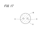
- FIG. 16 is a cross-sectional view of the ceramic guide as seen from the section line XVII-XVII in FIG. 15.
- FIG. 18 is a partial cross-sectional view showing a ceramic guide device using the ceramic guide shown in FIGS. 15 to 17; It is sectional drawing which shows the ceramic guide of other embodiment of this indication.
- FIG. 1 is a partial cross-sectional view illustrating a ceramic guide device using a ceramic guide according to an embodiment of the present disclosure.
- the ceramic guide device 1 of the present embodiment is a wire electrode 2 that is an insert made of a linear long material in order to obtain information on nerve activity from the brain of a small experimental animal such as a rodent or a marmoset. And a ceramic guide 3 preferably used for placing the wire electrode 2 in the brain.
- FIG. 2 is an enlarged side view of the ceramic guide
- FIG. 3 is a sectional view of the ceramic guide
- FIG. 4 is a sectional view taken along section line IV-IV of FIG. 2
- FIG. 5 is a sectional view of FIG. It is sectional drawing seen from the plane line VV.
- the ceramic guide 3 is formed of a columnar body having an insertion hole 6 through which the wire electrode 2 can be inserted, penetrating from the first end 4 to the second end 5.
- the ceramic guide 3 includes a columnar ceramic body, and the ceramic body has a first portion 7 having a first end 4, a second end 5, a second portion 8 having a smaller diameter than the first portion 7, and A third portion 9 that is coaxially connected between the first portion 7 and the second portion 8 is included.
- the outer peripheral surface 12 of the third portion 9 is curved in a direction approaching the central axis L1 from the peripheral edge 9a on the first portion 7 side toward the peripheral edge 9b on the second portion 8 side.
- the ceramic guide 3 and the ceramic body are substantially the same.
- the outer peripheral surface 12 of the third portion 9 is inclined in a direction approaching the central axis L1 from the peripheral edge 9a on the first portion 7 side toward the peripheral edge 9b on the second portion 8 side, that is, The shape which comprises the outer peripheral surface of an inverted truncated cone may be sufficient.
- Such a ceramic guide 3 is a living body, for example, the scalp 20 and skull 21 of the head of a small animal for experiment, the second portion 8 penetrates, the third portion 9 functions as a stopper, and the first portion 7 It is fixed in a state of protruding outward.
- the operator holds the first portion 7 of the ceramic guide 3 using tweezers and is attached to the measurement target portion of the head.
- the outer peripheral surface 11 of the first portion 7 may be roughened in another embodiment.
- the gripping force of the ceramic guide 3 by tweezers can be increased, the displacement of the ceramic guide 3 from the tweezers can be prevented, and excellent handling properties can be achieved.
- the wire electrode 2 is inserted into the insertion hole 6 of the ceramic guide 3 attached to a predetermined measurement target portion of the head.
- the wire electrode 2 is joined with a substantially spherical support piece 23 made of resin.
- the bonding position of the support piece 23 with respect to the wire electrode 2 is such that the support piece 23 is supported by a concave surface 16 to be described later in the state where the wire electrode 2 is inserted into the ceramic guide 3, and the distal end portion 2 a of the wire electrode 2 is in advance of the brain 24.
- the wire electrode 2 is bonded to the positioned position so that the wire electrode 2 is prevented from moving in the distal direction (downward in FIG. 1) in a state where the measurement target site is determined.
- the concave surface 16 is curved or inclined toward the second portion 8 as it approaches the central axis L1 from the outer edge 7a at the one end 4 of the first portion 7.
- an epoxy resin can be used as the material of the support piece 23, for example.
- the epoxy resin has a certain degree of viscosity and hardens into a ball shape after being attached to the wire electrode 2.
- a two-part epoxy resin “High Super” (registered trademark) 5 manufactured by Cemedine Co., Ltd. may be mentioned. Since this epoxy resin is cured in about 5 minutes, there is an advantage that the time for forming the support piece 23 on the wire electrode 2 can be shortened and it is easy to use.
- the wire electrode 2 attached to the ceramic guide 3 has a first protruding portion 25 protruding from the first end 4 of the ceramic guide 3 and a second protruding portion 26 protruding from the second end 5.
- the first protruding portion 25 is connected to a connector 31 to be described later.
- a lead wire 38 is connected to the connector 31, and the lead wire 38 is a predetermined external device, for example, an electroencephalogram (abbreviated as EEG) device 30 ( In FIG. 6, it is used to extract brain tissue activity information as an electrical signal.
- EEG electroencephalogram
- the electroencephalogram measurement apparatus 30 may be realized by a personal computer, for example.
- the first portion 7, the second portion 8, and the third portion 9 have a common center axis L1, and are integrally formed of ceramic.
- the outer peripheral surface 10 of the second portion 8 has a smaller diameter than the outer peripheral surface 11 of the first portion 7, and therefore the projection line when the outer peripheral surface 11 of the first portion 7 is projected onto a virtual plane perpendicular to the central axis L ⁇ b> 1 is
- the outer peripheral surface 10 of the second portion 8 is located radially outward from the projection line when projected onto a virtual plane perpendicular to the central axis L1.
- the material of the ceramic guide 3 examples include alumina (Al 2 O 3 ), zirconia (ZrO 2 ), aluminum nitride (AlN), silicon carbide (SiC), silicon nitride (Si 3 N 4 ), forsterite (2MgO ⁇ Basically, ceramics such as SiO 2 ), sialon (SiAlON), barium titanate (BaTiO 3 ), lead zirconate titanate (PZT), ferrite, and mullite can be used. In particular, zirconia is preferable in terms of excellent biocompatibility.
- the ceramic guide 3 may contain an additive when the material is zirconia. Examples of the additive include a stabilizer such as yttria.
- the ceramic guide 3 can be produced, for example, by the following steps. First, a powder of a ceramic raw material such as zirconia is kneaded together with a thermoplastic binder to produce a mixed material. Next, this mixed material is pressure-molded using a mold having a predetermined shape (space portion) of the ceramic guide 3 to produce a generated shape. Thereafter, the resulting shaped body is fired at a temperature of about 1300-1400 ° C.
- the ceramic body 3 made of ceramics containing zirconia can be manufactured through the above steps.
- the curved or inclined concave surface 16 as described above can be formed by making the mold used when producing the ceramic guide 3 have the same shape as the concave surface 16.
- the end surface may be subjected to post-processing such as polishing and grinding to provide the concave surface 16.
- the outer peripheral surface 12 of the third part 9 is curved in a direction approaching the central axis L1 from the peripheral edge 9a on the first part 7 side toward the peripheral edge 9b on the second part 8 side.
- the outer peripheral surface 12 of the third part 9 is inclined in a direction approaching the insertion hole 6 from the peripheral edge 9a on the first part 7 side toward the peripheral edge 9b on the second part 8 side, that is, The shape which comprises the outer peripheral surface of a truncated cone may be sufficient.
- Such a shape in which the outer peripheral surface 12 of the third portion 9 is curved can be formed by a method of adjusting the die or performing post-processing as in the case of the concave surface 16.
- the first portion 7 has a concave surface 16 that is curved toward the second end 5 as it approaches the central axis L ⁇ b> 1 from the outer edge 15.
- the concave surface 16 may have a configuration that is inclined toward the second portion 8 as it approaches the central axis L1 from the outer edge 15, that is, a shape that forms the outer peripheral surface of the truncated cone.
- each dimension of the ceramic guide 3 when measuring the activity information of the brain of the experimental small animal is as follows.
- Diameter D1: D1 1.25 mm of the outer peripheral surface 11 of the first portion 7
- Diameter D2 of outer peripheral surface 10 of second portion 8: D2 0.85 mm
- Inner diameter D3 of the insertion hole 6: D3 0.25 mm
- Diameter D4 of concave surface 16 of first end 15: D4 0.9 mm
- the elevation angle ⁇ of the concave surface 16: ⁇ 90 °
- Total length L1: L1 3mm
- First portion 7 length L2: L2 1.0 to 1.5 mm
- Length L3 of the second portion 8: L3 1.5 to 1.0 mm
- Length L4 of the third portion 8: L4 0.5 mm
- the dimensions of the ceramic guide 3 are not limited to this, and in other embodiments, appropriate dimensions may be adopted according to the type of measurement target, the measurement target site, and the like.
- the ceramic guide 3 uses a silver wire element that is reasonably soft and has a good shape, so that the wire electrode 2 was inserted into the cerebral cortex of the dura mater 22 and the brain 24. In this case, the deviation from the insertion path that may occur is reduced, the handling is excellent, and the indwelling operation becomes much easier and more accurate. Moreover, since the shape of the wire element made of silver can be flexibly changed by using tweezers, the wire electrode 2 can be inserted in such a manner that it is slid into the insertion hole 6 through the concave surface 16 of the ceramic guide 3. The tip 2a of the wire electrode 2 can smoothly reach the target measurement target site M in the brain 24 without causing problems such as bending during insertion.
- the dura mater 22 is a tough membrane tissue, and the cerebral cortex of the brain 24 is a brain tissue having a thickness of about 1 to 2 mm, but the distal end portion 2 a of the wire electrode 2 is guided to the insertion hole 6 by the concave surface 16.
- the operator grasps the wire electrode 2 using tweezers and manually places the distal end portion 2a of the wire electrode 2 into the space surrounded by the concave surface 16 and pushes the wire electrode 2 into the wire electrode. 2 is inserted into the insertion hole 6, and in this state, the support piece 23 comes into contact with the concave surface 16 to prevent further insertion of the wire electrode 2.
- the distal end portion 2 a of the wire electrode 2 can be easily and surely reached the target measurement target site M in the brain 24. This eliminates the need for large-scale insertion of the wire electrode 2 using a manipulator, and allows the wire electrode 2 to be easily inserted in a short time.
- the core wire of the wire electrode 2 is not limited to the above-described element wire made of silver, and in other embodiments, when handling suitable for an insertion target site, tissue, insertion depth, etc. can be realized,
- a wire having higher rigidity than silver such as tungsten, stainless steel, stainless alloy, or platinum may be used.
- a parallel electrode wire called “Twisted-wire” in which two coated wires obtained by coating a silver core wire having an outer diameter of about 50 ⁇ m with a polytetrafluoroethylene (registered trademark: Teflon) resin is bundled. Used.
- the outer diameter including the covering layer of the parallel electrode lines is about 110 ⁇ m.
- the single electrode wire one having a maximum outer diameter of about 180 ⁇ m including the coating layer that can be inserted into the insertion hole 6 can be used.
- a single electrode wire it is possible to measure one type of electroencephalogram called a local potential.
- FIG. 6 is a perspective view showing a schematic configuration of the ceramic guide module
- FIG. 7 is a plan view of the connector.
- the ceramic guide module 100 of the present embodiment is used as a system for sampling or modeling activity information of brain dynamics in a normal state and a diseased state of a small animal.
- the ceramic guide module 100 includes a plurality (10 in the present embodiment) of ceramic guides 3, a plurality of wire electrodes 2 inserted into the ceramic guides 3, and a connector 31 to which the wire electrodes 2 are connected.
- the connector 31 is made of an insulating material such as ceramic and insulating resin and is a board 32 having a rectangular plate shape in plan view, a plurality of input terminals 33 provided in alignment on one surface of the board 32, and the board 32. A plurality of output terminals 34 provided in alignment on the other surface, and internal wiring 35 that individually connects each input terminal 33 and each output terminal 34 inside the substrate 32 are configured.
- One of the plurality of output terminals 34 is connected to one input terminal of a differential amplifier 37 by a lead wire 36.
- the remaining output terminals 34 are connected to the other input terminal of the differential amplifier 37 by lead wires 38, respectively.
- FIG. 6 shows only one lead wire 38 and omits the remaining lead wires 38 for ease of illustration.
- the differential amplifier 37 obtains the difference between the reference signal input to one input terminal from the lead wire 36 and each reference signal input to the other input terminal of the differential amplifier 35 from each lead wire 38, respectively.
- the differential signal is subjected to predetermined signal processing such as waveform shaping and analog / digital conversion, and is output to the electroencephalogram measurement apparatus 30 as a measurement signal sampled for each wire electrode 2.
- the electroencephalogram measurement apparatus 30 includes a storage device and a display device, and the measurement signal output from the differential amplifier 35 is recorded in the storage device and displayed as a display image such as a signal waveform on the display screen of the display device.
- FIG. 8 is a view showing a state in which the ceramic guide and the wire electrode are placed in the brain section of the rat used in the experiment
- FIG. 9 is a state in which the ceramic guide and the wire electrode are removed from the brain section of the rat used in the experiment.
- the ceramic guide 3 is fixed to the head by being inserted into holes made in the scalp 20, skull 21 and dura 22 by aseptic surgery.
- the wire electrode 2 is inserted into the insertion hole 6 of the fixed ceramic guide 3, and the distal end portion 2 a of the wire electrode 2 is inserted into the tissue of the brain 24.
- the ceramic guide 3 and the wire electrode 2 are firmly fixed to the skull 21 by a bonding material 27 made of, for example, dental cement.
- a bonding material 27 made of, for example, dental cement.
- the wire electrode 2 is inserted into the brain 24 in a short time, for example within a few tens of minutes, and is stably placed over a long period of, for example, 2 to 3 months. Information such as action potential can be obtained stably.
- the bonding material 27 may cover the wire electrode 2 and at least a part (the skull side portion) of the connector 31 connected thereto. Further, the scalp 20 may cover the bonding material 27.
- the number of electrodes that can be placed in a conventional guide having a diameter of 5 mm or more, for example, is limited to one or two at most because of space limitations.
- the guide 3 has a diameter of 1.25 mm or less, can place a plurality of wire electrodes 2, and can measure and record brain activity information from multiple points.
- the experimental small animal is a rat, at least 16 wire electrodes 2 are placed.
- the ceramic guide 3 is excellent in that a configuration having a third portion 9 as a step is adopted instead of a simple cylinder. Since the third portion 9 serves as a stopper, it is possible to reliably prevent the skull 21 and the dura 22 from breaking through when the ceramic guide 3 is embedded in the living body. It is possible to produce the third portion 9 in an arbitrary size and in the order of microns by a highly accurate ceramic processing technique.
- the ceramic guide 3 has the third portion 9, the third portion 9 is located at the peripheral portion of the opening of the scalp 20 and the skull 21 with the second portion 8 inserted into the scalp 20, the skull 21, and the dura 22. It is possible to reduce the intrusion of the bonding material 27 and the like into the brain 24 from between the ceramic guide 3 and the skull 21 by press-fitting.
- FIG. 9 shows a state in which two ceramic guides 3 are embedded in a rat skull 40 (thickness: about 0.5 mm) and viewed from the back side (brain side).
- the step due to the third portion 9 on the outer peripheral surface serves as a stopper, and the second portion 8 of the ceramic guide 3 can be prevented from jumping out toward the brain 24 and damaging the brain 24.
- the ceramic guide 3 Since the ceramic guide 3 is resistant to heat and chemicals, it can be sterilized or sterilized by being immersed in an autoclave or disinfectant. Further, as shown in FIG. 10, since no rejection of the brain tissue is observed in the vicinity of the second portion 8 of the embedded ceramic guide 3, it is safe for long-term placement. In order to confirm this, the present inventor has left for one month and confirmed that no rejection has occurred. As shown by an arrow 41 in FIG. 10, by passing an electric current through the wire electrode 2 after the experiment and making a trace on the tissue of the brain 24, the tip 2a of the wire electrode 2 was indeed in the cerebral cortex, It was also confirmed that the cortical surface was not significantly damaged. In addition, the site
- the ceramic guide 3 of the present disclosure since the third portion 9 is provided in the ceramic guide 3, a hole formed in a living body by grasping the ceramic guide 3 with tweezers without using a manipulator. It can be simply attached to any attachment site such as, and the attachment time can be shortened. Since time is not required for attaching the ceramic guide 3, the living body restraining time is short, the influence on the living tissue is small, and the burden on the living body can be reduced. In particular, when the attachment site is a hole formed in the bone, the second portion 8 of the ceramic guide 3 can be fitted into the hole. A certain wire electrode 2 can be accurately positioned and fixed to the head together with the ceramic guide 3, and the stability of the wire electrode 2 to the living body can be improved.
- the ceramic guide 3 forms a small hole like the wire electrode 2 in the living body, and the second portion 8 is fitted into the hole, whereby the ceramic guide 3 is moved to the living body. Therefore, it is possible to use an appropriate ceramic guide according to the type and size of the target animal, thereby providing a degree of freedom in selecting the type of the wire electrode 2 that can be attached to the living body. Can be improved.
- FIG. 11 is a cross-sectional view showing a ceramic guide according to another embodiment of the present disclosure
- FIG. 12 is a cross-sectional view of the ceramic guide as viewed from the cutting plane line XII-XII in FIG. 11
- FIG. FIG. 14 is a cross-sectional view of the ceramic guide as seen from the plane line XIII-XIII
- FIG. 14 is a partial cross-sectional view showing a ceramic guide device using the ceramic guide shown in FIGS. Note that portions corresponding to those of the above-described embodiment are denoted by the same reference numerals, and redundant description is omitted.
- the insertion hole 6 extends coaxially with the central axis L ⁇ b> 1 of the ceramic guide 3 in the first portion 7 and the third portion 9, and approaches the other end 5 from one end 4 in the second portion 8. It is formed to curve outward in the radial direction.
- the tip 2a of the wire electrode 2 is a tissue M such as a nerve tissue or blood vessel. Can be guided to the side so as to avoid damage to the tissue M to be avoided.
- FIG. 15 is a cross-sectional view showing a ceramic guide according to still another embodiment of the present disclosure
- FIG. 16 is a plan view of the ceramic guide shown in FIG. 15
- FIG. 17 is a sectional view taken along the section line XVII-XVII in FIG.
- FIG. 18 is a partial cross-sectional view of a ceramic guide device using the ceramic guide shown in FIGS. 15 to 17. Note that portions corresponding to those of the above-described embodiment are denoted by the same reference numerals, and redundant description is omitted.
- two insertion holes 6 are formed in the ceramic guide 3 symmetrically with respect to the central axis L1.
- a single wire electrode 2 can be individually inserted into each insertion hole 6, and one can be used as a reference electrode and the other as a reference electrode.
- each wire electrode 6 can be inserted into the brain 24 while avoiding the tissue M to be avoided.
- the outer peripheral surface 11 of the first portion 7 may be formed into a rough surface.
- a blasting method in which an abrasive is sprayed may be used, or the outer peripheral surfaces 10 and 12 of the second and third portions 8 and 9 are masked.
- the ceramic guide 3 may be immersed in an etching solution, and only the outer peripheral surface 11 of the first portion 7 may be chemically eroded to form a rough surface.
- the scalp 20, the skull 21, the dura mater 22, and the brain 24 have been described as target sites for inserting or inserting the wire electrode 2.
- a living body is used.
- the insert may be, for example, a tube or a catheter. If it is a tube, a liquid or gas etc. can be flowed and the convenience on use can be improved.
- the ceramic guide 3 may have a cross section perpendicular to the central axis L1 in a polygonal shape such as a circle, a rectangle, a triangle, or a pentagon.
- the above-mentioned cross section of the ceramic guide 3 is basically circular and has a part of the circumference or is linear with respect to the axis, that is, the cross section perpendicular to the axis is D-shaped or substantially oval, etc.
- a plane portion may be provided at a part of the peripheral surface of the first portion 16 or at an axially symmetric portion. If there is such a flat portion, it can be easily held with tweezers and the like, so that handling becomes easier.
- a part of the outer peripheral surface of the first portion 16 may have a recess 50 that is recessed toward the central axis L1 as indicated by an imaginary line in FIG. Good.
- the bonding material 27 enters the recess 50, and the displacement such as rotation of the ceramic guide 3 and displacement in the length direction (vertical direction in FIG. 1) can be reduced.
Landscapes
- Health & Medical Sciences (AREA)
- Life Sciences & Earth Sciences (AREA)
- Veterinary Medicine (AREA)
- Surgery (AREA)
- Public Health (AREA)
- Engineering & Computer Science (AREA)
- General Health & Medical Sciences (AREA)
- Animal Behavior & Ethology (AREA)
- Pathology (AREA)
- Molecular Biology (AREA)
- Medical Informatics (AREA)
- Heart & Thoracic Surgery (AREA)
- Biomedical Technology (AREA)
- Physics & Mathematics (AREA)
- Biophysics (AREA)
- Wood Science & Technology (AREA)
- Zoology (AREA)
- Measurement And Recording Of Electrical Phenomena And Electrical Characteristics Of The Living Body (AREA)
Abstract
L'invention concerne un dispositif de guidage en céramique comprenant un guide en céramique en colonne et une électrode à fil allongé (2). Le guide en céramique en colonne comprend une première partie (7) comprenant une première extrémité (4), une deuxième partie comprenant une seconde extrémité (5) et ayant un diamètre plus petit que la première partie (7), et une troisième partie (9) disposée entre la première partie (7) et la deuxième partie (8). Le guide en céramique comporte un trou d'insertion (6) qui pénètre dans le guide en céramique de la première extrémité (4) à la seconde extrémité (5) et à travers lequel l'électrode à fil allongé (2) peut être insérée. L'électrode à fil allongé (2) passe à travers le trou d'insertion (6) et a une première partie en saillie (25) faisant saillie à partir de la première extrémité (4) et une seconde partie en saillie (26) faisant saillie à partir de la seconde extrémité (5).
Priority Applications (3)
| Application Number | Priority Date | Filing Date | Title |
|---|---|---|---|
| CN201980010747.6A CN111655143A (zh) | 2018-01-31 | 2019-01-31 | 陶瓷引导件、陶瓷引导件装置以及陶瓷引导件模块 |
| US16/966,235 US11944456B2 (en) | 2018-01-31 | 2019-01-31 | Ceramic guide, ceramic guide device, and cermic guide module |
| JP2019569594A JP7032712B2 (ja) | 2018-01-31 | 2019-01-31 | セラミックガイド、セラミックガイド装置およびセラミックガイドモジュール |
Applications Claiming Priority (2)
| Application Number | Priority Date | Filing Date | Title |
|---|---|---|---|
| JP2018-015924 | 2018-01-31 | ||
| JP2018015924 | 2018-01-31 |
Publications (1)
| Publication Number | Publication Date |
|---|---|
| WO2019151455A1 true WO2019151455A1 (fr) | 2019-08-08 |
Family
ID=67479809
Family Applications (1)
| Application Number | Title | Priority Date | Filing Date |
|---|---|---|---|
| PCT/JP2019/003520 Ceased WO2019151455A1 (fr) | 2018-01-31 | 2019-01-31 | Guide céramique, dispositif de guidage en céramique et module de guidage en céramique |
Country Status (4)
| Country | Link |
|---|---|
| US (1) | US11944456B2 (fr) |
| JP (1) | JP7032712B2 (fr) |
| CN (1) | CN111655143A (fr) |
| WO (1) | WO2019151455A1 (fr) |
Families Citing this family (3)
| Publication number | Priority date | Publication date | Assignee | Title |
|---|---|---|---|---|
| US12478730B2 (en) * | 2012-12-31 | 2025-11-25 | Medtg, Llc | Simultaneous infusion and blood collection devices |
| WO2021108624A1 (fr) * | 2019-11-26 | 2021-06-03 | Medtg, Llc | Dispositif et procédés de prélèvement et perfusion sanguins |
| CN116269411B (zh) * | 2023-03-26 | 2024-05-28 | 中国科学院昆明动物研究所 | 一种树鼩脑神经电生理记录电极装置 |
Citations (4)
| Publication number | Priority date | Publication date | Assignee | Title |
|---|---|---|---|---|
| US20040082875A1 (en) * | 2002-10-24 | 2004-04-29 | Brown University Research Foundation | Microstructured arrays for cortex interaction and related methods of manufacture and use |
| CN203662756U (zh) * | 2014-01-09 | 2014-06-25 | 杨丽红 | 一种动物实验心电图导联电极 |
| JP2017113358A (ja) * | 2015-12-25 | 2017-06-29 | 京セラ株式会社 | 針体、電子装置および供給装置 |
| CN206621358U (zh) * | 2016-11-04 | 2017-11-10 | 广东省人民医院 | 电极针 |
Family Cites Families (14)
| Publication number | Priority date | Publication date | Assignee | Title |
|---|---|---|---|---|
| JPH07303677A (ja) * | 1994-05-13 | 1995-11-21 | Itec:Kk | 注射針処理装置 |
| JP2001000555A (ja) * | 1999-06-22 | 2001-01-09 | Hirakawa Hewtech Corp | 先導子付きカテーテル及びその製造方法 |
| TW200538173A (en) * | 2004-05-31 | 2005-12-01 | Inst Of Whole Body Metabolism | Hollow needle and indwelling needle using the hollow needle |
| US7344560B2 (en) * | 2004-10-08 | 2008-03-18 | Boston Scientific Scimed, Inc. | Medical devices and methods of making the same |
| KR100905423B1 (ko) * | 2005-08-29 | 2009-07-02 | 가부시키가이샤 무라타 세이사쿠쇼 | 세라믹 전자 부품 및 그 제조 방법 |
| EP2207496A1 (fr) | 2007-10-08 | 2010-07-21 | Renishaw (Ireland) Limited | Dispositif pour chirurgie stéréotaxique |
| EP2211973A2 (fr) * | 2007-10-08 | 2010-08-04 | Renishaw (Ireland) Limited | Cathéter |
| WO2010038393A1 (fr) | 2008-09-30 | 2010-04-08 | 国立大学法人奈良先端科学技術大学院大学 | Dispositif de mesure d'informations intracérébrales |
| JP5673962B2 (ja) * | 2010-01-25 | 2015-02-18 | 国立大学法人九州工業大学 | 脳信号計測システム及び計測システム |
| JP5843201B2 (ja) | 2010-04-21 | 2016-01-13 | 国立大学法人東北大学 | 小動物用の脳測定用電極ユニットとそれを用いた測定システム |
| WO2012017950A1 (fr) | 2010-08-03 | 2012-02-09 | 学校法人 久留米大学 | Dispositif d'électrode électro-encéphalographique pour un petit animal de laboratoire et procédé électro-encéphalographique |
| US8764711B2 (en) * | 2011-02-28 | 2014-07-01 | Injectimed, Inc. | Needle guard |
| GB201117061D0 (en) * | 2011-10-04 | 2011-11-16 | Renishaw Ireland Ltd | Neurosurgical apparatus |
| CN107468316A (zh) * | 2017-09-12 | 2017-12-15 | 温州医科大学附属第二医院温州医科大学附属育英儿童医院 | 一种可调腹腔穿刺器 |
-
2019
- 2019-01-31 WO PCT/JP2019/003520 patent/WO2019151455A1/fr not_active Ceased
- 2019-01-31 CN CN201980010747.6A patent/CN111655143A/zh active Pending
- 2019-01-31 US US16/966,235 patent/US11944456B2/en active Active
- 2019-01-31 JP JP2019569594A patent/JP7032712B2/ja active Active
Patent Citations (4)
| Publication number | Priority date | Publication date | Assignee | Title |
|---|---|---|---|---|
| US20040082875A1 (en) * | 2002-10-24 | 2004-04-29 | Brown University Research Foundation | Microstructured arrays for cortex interaction and related methods of manufacture and use |
| CN203662756U (zh) * | 2014-01-09 | 2014-06-25 | 杨丽红 | 一种动物实验心电图导联电极 |
| JP2017113358A (ja) * | 2015-12-25 | 2017-06-29 | 京セラ株式会社 | 針体、電子装置および供給装置 |
| CN206621358U (zh) * | 2016-11-04 | 2017-11-10 | 广东省人民医院 | 电极针 |
Also Published As
| Publication number | Publication date |
|---|---|
| JPWO2019151455A1 (ja) | 2021-05-13 |
| US20210045688A1 (en) | 2021-02-18 |
| CN111655143A (zh) | 2020-09-11 |
| JP7032712B2 (ja) | 2022-03-09 |
| US11944456B2 (en) | 2024-04-02 |
Similar Documents
| Publication | Publication Date | Title |
|---|---|---|
| Hanson et al. | The “sewing machine” for minimally invasive neural recording | |
| Shi et al. | Application of a sub–0.1-mm3 implantable mote for in vivo real-time wireless temperature sensing | |
| US8170638B2 (en) | MEMS flexible substrate neural probe and method of fabricating same | |
| US20230371981A1 (en) | Methods, Compositions, and Systems for Device Implantation | |
| JP7032712B2 (ja) | セラミックガイド、セラミックガイド装置およびセラミックガイドモジュール | |
| US6560472B2 (en) | Multi-channel structurally robust brain probe and method of making the same | |
| Moxon et al. | Ceramic-based multisite electrode arrays for chronic single-neuron recording | |
| Kuo et al. | Novel flexible Parylene neural probe with 3D sheath structure for enhancing tissue integration | |
| US8489203B2 (en) | Biostable neuroelectrode | |
| US20070163106A1 (en) | Needle having multiple electrodes | |
| Kisban et al. | Microprobe array with low impedance electrodes and highly flexible polyimide cables for acute neural recording | |
| US11141112B2 (en) | Set for applying a flat, flexible two-dimensional thin-film strip into living tissue | |
| van Daal et al. | System for recording from multiple flexible polyimide neural probes in freely behaving animals | |
| Zhou et al. | Through-polymer, via technology-enabled, flexible, lightweight, and integrated devices for implantable neural probes | |
| US20150335257A1 (en) | Hyperdrive and Neuroprobes for Stimulation Purposes | |
| EP4151158B1 (fr) | Tube biomédical et dispositif biométrique | |
| JP2008212453A (ja) | 血管内診断のための超音波探触子及びその製造方法 | |
| US11675141B2 (en) | Optical connector ferrule, optical connector, and composite fiber connecting assembly | |
| US20230320695A1 (en) | Catheter-type ultrasound endoscope and examination system including same | |
| Yoshikawa et al. | Low-cost electroencephalographic recording system combined with a millimeter-sized coil to transcranially stimulate the mouse brain in vivo | |
| Jacobs et al. | Standard Operating Protocol: Implantation of Cambrige NeuroTech chronic silicon probe and mini-amp-64 digital headstage in mice | |
| Kisban et al. | Hybrid microprobes for chronic implantation in the cerebral cortex | |
| WO2020152628A2 (fr) | Dispositif d'accès à un tissu | |
| Kuo et al. | 3D Parylene sheath probes for reliable, long-term neuroprosthetic recordings | |
| CN111437514A (zh) | 用于同时实现深脑光刺激和脑电检测的光纤探头及制备方法 |
Legal Events
| Date | Code | Title | Description |
|---|---|---|---|
| 121 | Ep: the epo has been informed by wipo that ep was designated in this application |
Ref document number: 19746699 Country of ref document: EP Kind code of ref document: A1 |
|
| ENP | Entry into the national phase |
Ref document number: 2019569594 Country of ref document: JP Kind code of ref document: A |
|
| NENP | Non-entry into the national phase |
Ref country code: DE |
|
| 122 | Ep: pct application non-entry in european phase |
Ref document number: 19746699 Country of ref document: EP Kind code of ref document: A1 |