WO2019155509A1 - Dispositif de frein électromagnétique, treuil et ascenseur - Google Patents
Dispositif de frein électromagnétique, treuil et ascenseur Download PDFInfo
- Publication number
- WO2019155509A1 WO2019155509A1 PCT/JP2018/003922 JP2018003922W WO2019155509A1 WO 2019155509 A1 WO2019155509 A1 WO 2019155509A1 JP 2018003922 W JP2018003922 W JP 2018003922W WO 2019155509 A1 WO2019155509 A1 WO 2019155509A1
- Authority
- WO
- WIPO (PCT)
- Prior art keywords
- electromagnetic
- movable member
- rubber
- main body
- electromagnetic core
- Prior art date
- Legal status (The legal status is an assumption and is not a legal conclusion. Google has not performed a legal analysis and makes no representation as to the accuracy of the status listed.)
- Ceased
Links
Images


Classifications
-
- B—PERFORMING OPERATIONS; TRANSPORTING
- B66—HOISTING; LIFTING; HAULING
- B66B—ELEVATORS; ESCALATORS OR MOVING WALKWAYS
- B66B11/00—Main component parts of lifts in, or associated with, buildings or other structures
- B66B11/04—Driving gear ; Details thereof, e.g. seals
- B66B11/08—Driving gear ; Details thereof, e.g. seals with hoisting rope or cable operated by frictional engagement with a winding drum or sheave
Definitions
- the present invention relates to an electromagnetic brake device that performs driving braking of a sheave, a hoisting machine having the electromagnetic brake device, and an elevator.
- an elevator has a car, a counterweight, a rope that connects the car and the counterweight, and a hoisting machine on which the rope is wound.
- the hoisting machine has a drive unit, a rotary shaft connected to the drive unit, a sheave supported rotatably on the rotary shaft and wound with a rope, and a brake disk connected to the sheave. doing. Further, the hoisting machine is provided with an electromagnetic brake device that brakes the sheave by braking the rotation of the brake disk.
- Patent Document 1 discloses a technique related to an electromagnetic brake device including an electromagnetic coil wound around a fixed iron core, an amateur disposed opposite to the fixed iron core, and a compression coil spring disposed between the fixed iron core and the amateur. Is described. Patent Document 1 describes that a rubber that is inserted into a circular rubber insertion hole formed on a fixed iron core or an opposing surface of the amateur and serves as a buffer when the amateur is attracted by an electromagnet is described.
- Patent Document 1 when the shock absorbing rubber is compressed and elastically deformed, the side surface of the shock absorbing rubber expands outward in the radial direction, and the shock absorbing rubber comes into contact with the side wall of the accommodating portion where the shock absorbing rubber is accommodated. Therefore, the technique described in Patent Document 1 has a problem in that a reaction force greater than the design value is generated in the shock absorbing rubber due to the side surface contacting the side wall, and the movable member cannot be attracted to the electromagnetic core side. Had. Furthermore, when the shock absorbing rubber is compressed, the expanded side surface portion enters between the electromagnetic core and the movable member, and the movable member cannot be attracted to the electromagnetic core side.
- the purpose of the present invention is to provide an electromagnetic brake device, a hoisting machine, and an elevator that can obtain the reaction force of the shock absorbing rubber as designed when the shock absorbing rubber is compressed in consideration of the above problems.
- the electromagnetic brake device is an electromagnetic brake device that brakes the driving of a sheave of an elevator.
- the electromagnetic brake device includes a brake shoe, a movable member, an electromagnetic core, an urging spring, and a shock absorbing rubber.
- the brake shoe contacts a braked body that rotates with the sheave.
- the movable member supports the brake shoe.
- the electromagnetic core faces the movable member and is provided with an electromagnetic coil.
- the biasing spring biases the movable member in a direction away from the electromagnetic core.
- the buffer rubber is accommodated in a rubber accommodating portion provided in the electromagnetic core, and is interposed between the movable member and the electromagnetic core.
- the cushion rubber contacts the movable member, and the main body portion is placed in a state where a gap is formed between the main body portion compressed by the movable member and the electromagnetic core, and the side surface portion of the main body portion and the side wall of the rubber accommodating portion. And a support piece supported in the rubber container.
- the hoisting machine is a hoisting machine having a sheave on which a rope is wound, and has a braked body that is fixed to the sheave and rotates with the sheave, and a brake shoe that contacts the braked body, And an electromagnetic brake device for braking the driving of the sheave. And the electromagnetic brake device mentioned above is used for the electromagnetic brake device.
- the elevator is an elevator equipped with a car that moves up and down in the hoistway, A rope connected to the car, and a hoisting machine that has a sheave around which the rope is wound and moves the car up and down via the rope. And the hoisting machine mentioned above is used for the hoisting machine.
- the reaction force of the shock absorbing rubber as designed can be obtained when the shock absorbing rubber is compressed.
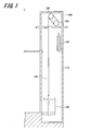
- FIG. 1 is a schematic configuration diagram illustrating a configuration example of the elevator according to the present example.
- the elevator 1 of this example is provided in a hoistway 110 formed in a building structure.
- the elevator 1 moves up and down in the hoistway 110 and includes a car 120 on which people and luggage are placed, a rope 130, a counterweight 140, and a hoisting machine 100.
- a machine room 160 is provided at the top of the hoistway 110.
- the hoisting machine 100 is disposed in the machine room 160 and raises and lowers the car 120 by winding the rope 130. Further, in the vicinity of the hoisting machine 100, a warping wheel 150 on which the rope 130 is mounted is provided.
- a cage 120 is attached to one end of the rope 130 in the axial direction, and a counterweight 140 is attached to the other end of the rope 130 in the axial direction. Therefore, the car 120 is connected to the counterweight 140 via the rope 130. Then, when the hoisting machine 100 is driven, the car 120 moves up and down in the hoistway 110.
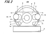
- FIG. 2 is a front view showing the hoisting machine 100
- FIG. 3 is a side view showing the hoisting machine 100.
- the hoisting machine 100 includes a machine base 2, a drive motor 3, a sheave 4, a brake disk 5, a bearing base 6, a fixing member 7, and two electromagnetic brakes.
- a drive motor 3, a bearing base 6, and a fixing member 7 are installed on the machine base 2.
- Rotating shaft 8 is connected to drive motor 3.
- a sheave 4 and a brake disk 5 showing an example of a braked body are attached to the rotating shaft 8.
- a rope 130 is wound around the sheave 4.
- a bearing stand 6 is provided between the sheave 4 and the drive motor 3. The end of the rotating shaft 8 on the drive motor 3 side is rotatably supported by the bearing base 6.
- Brake disc 5 is provided on the side of sheave 4 opposite to bearing stand 6.
- the brake disc 5 is fixed to the sheave 4 and is attached to the rotary shaft 8 together with the sheave 4.
- a fixing member 7 is disposed at the end of the rotary shaft 8 opposite to the end of the drive motor 3.
- the fixing member 7 has a bearing portion 7a that rotatably supports the rotary shaft 8, and two support portions 9 and 9.
- the two support portions 9 and 9 protrude on both sides in the horizontal direction with the bearing portion 7a interposed therebetween.
- the two support portions 9 and 9 have the same configuration.
- the support part 9 has a pair of arm pieces 11 and 11.
- the pair of arm pieces 11 and 11 are opposed to each other with a predetermined interval in the vertical direction.
- An electromagnetic brake device 10 is attached to the pair of arm pieces 11 and 11.
- the present invention is not limited thereto.
- the direction in which the support portion 9 is protruded is not limited to the horizontal direction, and may be protruded in the vertical direction or in a direction inclined from the horizontal direction and the vertical direction.
- the pair of arm pieces 11 and 11 may be opposed to each other at least along the circumferential direction of the brake disk 5.
- a guide plate 12 and a guide pin 13 are provided at the end of the arm piece 11 opposite to the bearing portion 7a.
- the guide plate 12 faces the arm piece 11 along the axial direction of the rotation shaft 8.
- the guide pin 13 is fixed to the guide plate 12 and the arm piece 11 so as to connect the guide plate 12 and the arm piece 11.
- a floating member 16 is provided in the vicinity of the guide pin 13 in the arm piece 11.
- a regulation pin 15 is fixed to the end portions of the pair of arm pieces 11, 11 facing each other.
- the electromagnetic brake device 10 includes a body 21, an electromagnetic drive unit 22, a first brake shoe 23, and a second brake shoe 24.
- the body 21 includes a frame body 26 and a support plate 27.
- the frame body 26 is formed in a shape that covers a part of the peripheral edge of the brake disc 5.
- a first brake shoe 23 is attached to an inner wall surface of the frame body 26 facing the one surface of the brake disk 5.
- a brake pad of the first brake shoe 23 faces one surface of the brake disc 5.
- a support plate 27 is continuously formed on the frame body 26.
- the support plate 27 is formed in a substantially flat plate shape.
- the support plate 27 faces the other surface of the brake disc 5 opposite to the one surface.
- a part of the support plate 27 faces the inner wall surface of the frame body 26 with the brake disk 5 interposed therebetween.
- the outer edge portion of the support plate 27 is inserted between the arm piece 11 and the guide plate 12.
- the guide pin 13 is slidably inserted into the outer edge portion of the support plate 27. Thereby, the body 21 is supported by the arm piece 11 through the two guide pins 13 so as to be movable.
- the floating member 16 is fixed to the outer edge portion of the support plate 27. One end of the floating member 16 is fixed to the support plate 27, and the other end penetrates the arm piece 11. A floating spring is interposed between the other end of the floating member 16 and the arm piece 11. The body 21 is urged by the floating spring in a direction in which the first brake shoe 23 is brought into contact with one surface of the brake disk 5.
- a through hole is formed in a portion of the support plate 27 facing the inner wall surface of the frame body 26.
- the brake shaft 24a of the second brake shoe 24 passes through the through hole.
- the electromagnetic drive part 22 is arrange
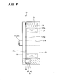
- FIG. 4 is a side view showing the electromagnetic drive unit 22
- FIG. 5 is a front view showing the electromagnetic core 31 constituting the electromagnetic drive unit 22.
- the electromagnetic drive unit 22 includes an electromagnetic core 31, a movable member 32 facing the electromagnetic core 31, an electromagnetic coil 37, a plurality of urging springs 38, and a plurality (in this example). 4) buffer rubber 40.
- the movable member 32 is formed in a substantially circular flat plate shape.
- a second brake shoe 24 is attached to the movable member 32 via a brake shaft 24a.
- the second brake shoe 24 has a brake shaft 24a and a brake pad.
- the brake shaft 24a is attached to the approximate center in the radial direction of the movable member 32, and penetrates from one end to the other end of the movable member 32 in the axial direction.
- the one end part of the axial direction in the brake shaft 24a has penetrated the through-hole of the support plate 27 (refer FIG. 3).
- a brake pad is provided at one end of the brake shaft 24a in the axial direction.
- the brake pad of the second brake shoe 24 faces the other surface of the brake disc 5. Further, the brake pad of the second brake shoe 24 is disposed to face the brake pad of the first brake shoe 23 with the brake disc 5 interposed therebetween.
- the brake pad of the first brake shoe 23 and the brake pad of the second brake shoe 24 come into contact with the brake disc 5. Therefore, the brake disc 5 is sandwiched between the brake pad of the first brake shoe 23 and the brake pad of the second brake shoe 24, and the brake disc 5 and the sheave 4 in the hoisting machine 100 are braked.
- the other end of the brake shaft 24 a in the axial direction that is, the end of the movable member 32 that protrudes from the facing surface 32 a that faces the electromagnetic core 31 protrudes toward the electromagnetic core 31.
- the electromagnetic core 31 is formed in a substantially cylindrical shape.
- the electromagnetic core 31 is formed with a mounting groove 31b, a plurality of spring accommodating portions 31c, a shaft support hole 31d, and a plurality of rubber accommodating portions 33.
- the mounting groove 31b is a recess that is recessed from the magnetic pole surface 31a facing the facing surface 32a of the movable member 32 in the electromagnetic core 31 in a direction away from the movable member 32.
- the electromagnetic coil 37 is fixed to the mounting groove 31b by a fixing means such as a fixing resin.
- the electromagnetic coil 37 is wound with a predetermined number of turns. A voltage is applied to the electromagnetic coil 37 by being controlled by a control unit (not shown). By applying a voltage to the electromagnetic coil 37, the electromagnetic core 31 and the electromagnetic coil 37 constitute an electromagnet.
- the magnetic pole surface 31 a facing the movable member 32 in the electromagnetic core 31 becomes an adsorption surface that adsorbs the movable member 32.
- the shaft support hole 31d is formed substantially at the center in the radial direction of the magnetic pole surface 31a.
- the shaft support hole 31d penetrates the electromagnetic core 31 from one end to the other end in the axial direction.
- the brake shaft 24a of the second brake shoe 24 provided in the movable member 32 is slidably inserted into the shaft support hole 31d. Thereby, the movable member 32 is supported by the electromagnetic core 31 via the second brake shoe 24 so as to be able to approach and separate.
- the plurality of spring accommodating portions 31 c and the plurality of rubber accommodating portions 33 are arranged on the outer side in the radial direction with respect to the mounting groove portion 31 b in the electromagnetic core 31. Further, the plurality of spring accommodating portions 31 c and the plurality of rubber accommodating portions 33 are alternately formed in the circumferential direction of the electromagnetic core 31.
- the spring accommodating portion 31 c and the rubber accommodating portion 33 are concave portions that are recessed in a substantially cylindrical shape in a direction away from the movable member 32 from the magnetic pole surface 31 a of the electromagnetic core 31.
- An urging spring 38 is disposed in the spring accommodating portion 31c.
- the biasing spring 38 for example, a compression coil spring is used.
- the biasing spring 38 is accommodated in the spring accommodating portion 31 c of the electromagnetic core 31 and is interposed between the electromagnetic core 31 and the movable member 32.
- One end of the urging spring 38 abuts against the facing surface 32a of the movable member 32, and the other end of the urging spring 38 is disposed in the spring accommodating portion 31c. Then, the biasing spring 38 biases the movable member 32 in a direction in which the movable member 32 is separated from the electromagnetic core 31 by a predetermined biasing force.
- a buffer rubber 40 is fitted in the rubber accommodating portion 33.
- the buffer rubber 40 is formed of rubber having elasticity.
- FIG. 6 is a cross-sectional view showing the rubber accommodating portion 33 in the electromagnetic core 31.
- the buffer rubber 40 includes a main body 41 and a support piece 42.
- the main body 41 is formed in a substantially cylindrical shape.
- the diameter of the main body 41 is set smaller than the inner diameter of the rubber accommodating portion 33.
- the shape of the main body 41 is not limited to a substantially cylindrical shape, and may be formed in a prismatic shape.
- the main body portion 41 has one axial end portion protruding outward from the rubber accommodating portion 33. As shown in FIG. 6, one end surface 41 a at one end of the main body 41 in the axial direction is in contact with the facing surface 32 a of the movable member 32.
- the support piece 42 is provided at the other end of the main body 41 in the axial direction.
- the support piece 42 is a flange that protrudes outward in the radial direction from the side surface portion 41 b of the main body portion 41.
- the axial length (height) d1 of the support piece 42 is set to be equal to or less than half of the axial length (height) of the main body 41.
- the diameter of the support piece 42 is set to be equal to or slightly smaller than the inner diameter of the rubber accommodating portion 33. In consideration of the efficiency of the installation work of the buffer rubber 40, the diameter of the support piece 42 is preferably slightly smaller than the inner diameter of the rubber accommodating portion 33.
- the support piece 42 When the buffer rubber 40 is accommodated in the rubber accommodating portion 33, the support piece 42 is placed on the bottom surface portion 33 a of the rubber accommodating portion 33. Further, the support piece 42 faces or contacts the side wall 33 b of the rubber accommodating portion 33. As a result, the main body 41 is supported by the support piece 42 in a state of being disposed at the approximate center of the rubber accommodating portion 33.
- the diameter of the support piece 42 is formed larger than the diameter of the main body 41. Therefore, a predetermined gap is formed between the side surface portion 41 b of the main body portion 41 and the side wall 33 b of the rubber accommodating portion 33.
- the distance d2 between the side surface portion 41b of the main body portion 41 and the side wall 33b of the rubber accommodating portion 33 is set to a length that prevents the side surface portion 41b from contacting the side wall 33b even if the main body portion 41 is elastically deformed.
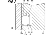
- FIG. 7 is a cross-sectional view showing a state where the buffer rubber 40 is compressed.
- the brake pad of the second brake shoe 24 attached to the movable member 32 is pressed against the other surface of the brake disc 5.
- the movable member 32 moves away from the electromagnetic core 31, that is, toward the one side in the axial direction of the rotating shaft 8 (see FIG. 3). The movement stops.
- the electromagnetic core 31 is urged in a direction away from the movable member 32 by the urging spring 38 and moves in a direction away from the other surface of the brake disk 5.
- the body 21 connected with the electromagnetic core 31 via the connection member not shown also moves to the other side of the axial direction of the rotating shaft 8 (refer FIG. 3) with the electromagnetic core 31.
- FIG. 3 As a result, the brake pad of the first brake shoe 23 provided on the body 21 is pressed against one surface of the brake disc 5.
- the brake disc 5 is sandwiched between the first brake shoe 23 and the second brake shoe 24, and the brake disc 5 and the sheave 4 are braked.
- the one end surface 41a of the buffer rubber 40 is in contact with the opposing surface 32a of the movable member 32. Therefore, vibration generated when the brake pads of the first brake shoe 23 and the brake pads of the second brake shoe 24 contact the brake disc 5 is absorbed by the buffer rubber 40. Thereby, the noise generated when the electromagnetic brake device 10 brakes can be reduced by the buffer rubber 40.
- the facing surface 32 a of the movable member 32 comes into contact with the regulation pin 15. Thereby, the movement in the direction which approaches the electromagnetic core 31 in the movable member 32 stops.
- a gap is still formed between the facing surface 32a of the movable member 32 and the magnetic pole surface 31a of the electromagnetic core 31, and the electromagnetic attracting force of the electromagnetic core 31 and the electromagnetic coil 37 acts on the movable member 32.
- the movement of the movable member 32 is restricted by the restriction pin 15.
- the electromagnetic attractive force generated in the electromagnetic core 31 and the electromagnetic coil 37 acts on the electromagnetic core 31, and the direction in which the electromagnetic core 31 approaches the movable member 32, that is, the axial direction of the rotary shaft 8 (see FIG. 3).
- the body 21 connected to the electromagnetic core 31 also moves to one side in the axial direction of the rotating shaft 8 (see FIG. 3) together with the electromagnetic core 31.
- the magnetic pole surface 31a of the electromagnetic core 31 and the opposing surface 32a of the movable member 32 come into contact with each other.
- the main body 41 of the buffer rubber 40 is compressed against the elastic force. Therefore, the moving speed when the electromagnetic core 31 and the movable member 32 come into contact with each other is reduced by the buffer rubber 40, and vibration generated when the electromagnetic core 31 and the movable member 32 come into contact with each other is absorbed by the buffer rubber 40.
- the contact rubber generated when the electromagnetic core 31 and the movable member 32 come into contact with each other can be reduced by the buffer rubber 40.
- the main body portion 41 is compressed, so that the side surface portion 41 b of the main body portion 41 expands outward in the radial direction in the rubber accommodating portion 33.
- a gap is formed between the side surface portion 41b of the main body portion 41 and the side wall 33b of the rubber housing portion 33 with a predetermined distance d2.
- the shock absorbing rubber 40 when the shock absorbing rubber 40 is compressed, it is possible to prevent the reaction force that is larger than the design value from being generated in the main body 41 due to the side surface portion 41b coming into contact with the side wall 33b.
- the reaction force of the buffer rubber can be obtained.
- the side surface portion 41 b can be prevented from being sandwiched between the magnetic pole surface 31 a of the electromagnetic core 31 and the opposing surface 32 a of the movable member 32.
- the position is the position where the position expands most half of its height. Therefore, when the height d1 of the support piece 42 that contacts the side wall 33b of the rubber accommodating part 33 is more than half the height of the main body part 41, the support piece 42 expands and presses against the side wall 33b, and the reaction force increases. It becomes a factor to do.
- the height d1 of the support piece 42 is set to be equal to or less than half the height of the main body 41. Therefore, it can prevent that the support piece 42 which supports the main-body part 41 expand
- the electromagnetic brake device 10 of this example since it can suppress that the side part 41b of the main-body part 41 in the buffer rubber 40 contacts the side wall 33b, it is not necessary to enlarge the opening diameter of the rubber accommodating part 33. Thereby, it can prevent that the area of the magnetic pole surface 31a of the electromagnetic core 31 reduces because the opening diameter of the rubber accommodating part 33 becomes large. As a result, the electromagnetic core 31 can be prevented from increasing in size in order to obtain a required magnetic force, and the entire electromagnetic brake device 10 can be reduced in size.
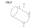
- FIG. 8 is a perspective view showing the shock absorbing rubber of the electromagnetic brake device according to the second embodiment
- FIG. 9 is a front view showing a state where the shock absorbing rubber is installed in the electromagnetic core.
- the electromagnetic brake device according to the second embodiment is different from the electromagnetic brake device 10 according to the first embodiment in the configuration of the buffer rubber. Therefore, here, the shock-absorbing rubber will be described, and portions that are the same as those of the electromagnetic brake device 10 according to the first embodiment will be given the same reference numerals and redundant description will be omitted.
- the buffer rubber 60 has a main body 61 formed in a columnar shape and a plurality (three in the second embodiment) support pieces 62. Since the configuration of the main body 61 is the same as that of the main body 41 of the shock absorbing rubber 40 according to the first embodiment, the description thereof is omitted here.
- the support piece 62 is provided at the other end of the main body 61 in the axial direction.
- the plurality of support pieces 62 are provided at equal intervals along the circumferential direction of the side surface portion 61 b of the main body portion 61.
- the support piece 62 is a protrusion that protrudes from the side surface portion 61b in a substantially hemispherical shape.
- the three support pieces 62 are arranged on the side surface portion 61b of the main body portion 61 at equal intervals. Accordingly, the main body 61 can be supported in a well-balanced manner in the rubber accommodating portion 33, and the main body 61 can be prevented from being shifted to the side wall 33b in the rubber accommodating portion 33.
- the number of support pieces 62 is not limited to three, and two or four or more support pieces 62 may be provided. However, in order to arrange the main body 61 in the rubber accommodating portion 33 with good balance, it is preferable to provide three or more support pieces 62.
- the support piece 62 is not limited to a substantially hemispherical shape, and may be formed in a prismatic shape or other various shapes.
- the present invention is not limited to this.
- a rubber accommodating portion made of a rod-shaped member having a recess may be attached to the electromagnetic core, and a buffer rubber may be provided on the electromagnetic core via the rubber accommodating portion.
- the example in which the sheave is braked by sandwiching the brake disk indicating the braked body between the first brake shoe and the second brake shoe as the electromagnetic brake device has been described. It is not limited to.
- a drum member that rotates together with the sheave as a braked body may be applied, and as the electromagnetic brake device, the sheave may be braked by pressing a brake shoe supported by the movable member against the drum member. That is, various other configurations can be applied as a configuration for braking the sheave in the electromagnetic brake device.
- Electromagnetic brake device 21 ... Body, 22 ... Electromagnetic drive unit, 23 ... first brake shoe, 24 ... second brake shoe (brake shoe), 31 ... electromagnetic core, 31a ... magnetic pole surface, 31b ... mounting groove part, 31c ... spring accommodating part, 31d ... shaft support hole, 32 ... movable member, 32a ... opposing surface, 33 ... rubber accommodating part, 33a ... bottom face part, 33b ... side wall, 37 ... electromagnetic coil, 38 ...
- biasing spring 40, 60 ... shock absorbing rubber, 41, 61 ... main body part, 41a ... one end face, 41b, 61b ... side face part, 42, 62 ... support piece, 100 ... hoisting machine, 110 ... hoistway, 120 ... ride car, 13 ... rope, 140 ... counterweight, 150 ... deflector sheave, 160 ... machine room
Landscapes
- Engineering & Computer Science (AREA)
- Civil Engineering (AREA)
- Mechanical Engineering (AREA)
- Structural Engineering (AREA)
- Cage And Drive Apparatuses For Elevators (AREA)
- Braking Arrangements (AREA)
Abstract
L'invention concerne un dispositif de frein électromagnétique, qui est pourvu : d'un sabot de frein ; d'un élément mobile ; d'un noyau électromagnétique ; d'un ressort de sollicitation ; et d'un caoutchouc d'amortissement. Le caoutchouc d'amortissement présente : un corps qui est amené en contact avec l'élément mobile et qui est comprimé par l'élément mobile et le noyau électromagnétique ; et une pièce de support qui soutient le corps dans une partie de logement de caoutchouc dans un état dans lequel un espace est ménagé entre une surface latérale du corps et une paroi latérale de la partie de logement de caoutchouc.
Priority Applications (2)
| Application Number | Priority Date | Filing Date | Title |
|---|---|---|---|
| PCT/JP2018/003922 WO2019155509A1 (fr) | 2018-02-06 | 2018-02-06 | Dispositif de frein électromagnétique, treuil et ascenseur |
| JP2019571131A JP7092805B2 (ja) | 2018-02-06 | 2018-02-06 | 電磁ブレーキ装置、巻上機及びエレベーター |
Applications Claiming Priority (1)
| Application Number | Priority Date | Filing Date | Title |
|---|---|---|---|
| PCT/JP2018/003922 WO2019155509A1 (fr) | 2018-02-06 | 2018-02-06 | Dispositif de frein électromagnétique, treuil et ascenseur |
Publications (1)
| Publication Number | Publication Date |
|---|---|
| WO2019155509A1 true WO2019155509A1 (fr) | 2019-08-15 |
Family
ID=67548957
Family Applications (1)
| Application Number | Title | Priority Date | Filing Date |
|---|---|---|---|
| PCT/JP2018/003922 Ceased WO2019155509A1 (fr) | 2018-02-06 | 2018-02-06 | Dispositif de frein électromagnétique, treuil et ascenseur |
Country Status (2)
| Country | Link |
|---|---|
| JP (1) | JP7092805B2 (fr) |
| WO (1) | WO2019155509A1 (fr) |
Cited By (3)
| Publication number | Priority date | Publication date | Assignee | Title |
|---|---|---|---|---|
| JP7262652B1 (ja) | 2022-08-30 | 2023-04-21 | 三菱電機ビルソリューションズ株式会社 | エレベータ用ブレーキ装置及びエレベータ用ブレーキ装置の検査方法 |
| JP7619403B1 (ja) | 2023-08-16 | 2025-01-22 | 三菱電機ビルソリューションズ株式会社 | ブレーキ装置及び緩衝部材 |
| JP7706627B1 (ja) * | 2024-11-12 | 2025-07-11 | 三菱電機ビルソリューションズ株式会社 | ブレーキ装置及びエレベータ巻上機 |
Families Citing this family (1)
| Publication number | Priority date | Publication date | Assignee | Title |
|---|---|---|---|---|
| WO2020021666A1 (fr) * | 2018-07-25 | 2020-01-30 | 株式会社Fuji | Dispositif de détermination et appareil d'installation de puce équipé de celui-ci |
Citations (7)
| Publication number | Priority date | Publication date | Assignee | Title |
|---|---|---|---|---|
| JPS6215630U (fr) * | 1985-07-12 | 1987-01-30 | ||
| JPH0873143A (ja) * | 1994-09-06 | 1996-03-19 | Toshiba Corp | エレベータ巻上機用ディスク形電磁ブレーキ |
| JP2000220674A (ja) * | 1999-02-01 | 2000-08-08 | Tsubakimoto Chain Co | 無励磁作動型電磁ブレーキの消音装置 |
| JP2007064247A (ja) * | 2005-08-29 | 2007-03-15 | Mitsubishi Electric Corp | 電磁ブレーキ装置 |
| JP2008120524A (ja) * | 2006-11-13 | 2008-05-29 | Mitsubishi Electric Corp | エレベータ用巻上機の電磁ブレーキ装置 |
| JP2015230020A (ja) * | 2014-06-04 | 2015-12-21 | Ntn株式会社 | 電磁連結装置 |
| JP2017182889A (ja) * | 2016-03-28 | 2017-10-05 | 三菱電機株式会社 | 電磁開閉器 |
Family Cites Families (1)
| Publication number | Priority date | Publication date | Assignee | Title |
|---|---|---|---|---|
| JP2017030940A (ja) | 2015-08-04 | 2017-02-09 | 株式会社日立製作所 | ブレーキ装置、巻上機及びエレベーター装置 |
-
2018
- 2018-02-06 WO PCT/JP2018/003922 patent/WO2019155509A1/fr not_active Ceased
- 2018-02-06 JP JP2019571131A patent/JP7092805B2/ja active Active
Patent Citations (7)
| Publication number | Priority date | Publication date | Assignee | Title |
|---|---|---|---|---|
| JPS6215630U (fr) * | 1985-07-12 | 1987-01-30 | ||
| JPH0873143A (ja) * | 1994-09-06 | 1996-03-19 | Toshiba Corp | エレベータ巻上機用ディスク形電磁ブレーキ |
| JP2000220674A (ja) * | 1999-02-01 | 2000-08-08 | Tsubakimoto Chain Co | 無励磁作動型電磁ブレーキの消音装置 |
| JP2007064247A (ja) * | 2005-08-29 | 2007-03-15 | Mitsubishi Electric Corp | 電磁ブレーキ装置 |
| JP2008120524A (ja) * | 2006-11-13 | 2008-05-29 | Mitsubishi Electric Corp | エレベータ用巻上機の電磁ブレーキ装置 |
| JP2015230020A (ja) * | 2014-06-04 | 2015-12-21 | Ntn株式会社 | 電磁連結装置 |
| JP2017182889A (ja) * | 2016-03-28 | 2017-10-05 | 三菱電機株式会社 | 電磁開閉器 |
Cited By (5)
| Publication number | Priority date | Publication date | Assignee | Title |
|---|---|---|---|---|
| JP7262652B1 (ja) | 2022-08-30 | 2023-04-21 | 三菱電機ビルソリューションズ株式会社 | エレベータ用ブレーキ装置及びエレベータ用ブレーキ装置の検査方法 |
| JP2024033342A (ja) * | 2022-08-30 | 2024-03-13 | 三菱電機ビルソリューションズ株式会社 | エレベータ用ブレーキ装置及びエレベータ用ブレーキ装置の検査方法 |
| JP7619403B1 (ja) | 2023-08-16 | 2025-01-22 | 三菱電機ビルソリューションズ株式会社 | ブレーキ装置及び緩衝部材 |
| JP2025027558A (ja) * | 2023-08-16 | 2025-02-28 | 三菱電機ビルソリューションズ株式会社 | ブレーキ装置及び緩衝部材 |
| JP7706627B1 (ja) * | 2024-11-12 | 2025-07-11 | 三菱電機ビルソリューションズ株式会社 | ブレーキ装置及びエレベータ巻上機 |
Also Published As
| Publication number | Publication date |
|---|---|
| JP7092805B2 (ja) | 2022-06-28 |
| JPWO2019155509A1 (ja) | 2020-12-10 |
Similar Documents
| Publication | Publication Date | Title |
|---|---|---|
| WO2019155509A1 (fr) | Dispositif de frein électromagnétique, treuil et ascenseur | |
| JP5985048B2 (ja) | ブレーキ装置、それを用いたエレベータ用巻上機、及びブレーキ装置の緩衝反力調整方法 | |
| JP5911042B2 (ja) | ブレーキ装置、及びそれを用いたエレベータ用巻上機 | |
| CN108285103B (zh) | 卷扬机以及电梯 | |
| KR100512806B1 (ko) | 엘리베이터 권양기 및 그의 브레이크 장치 | |
| JP6697792B2 (ja) | エレベータの巻上機ブレーキ及びエレベータ巻上機 | |
| JPWO2010143298A1 (ja) | エレベータ用巻上機のブレーキ装置 | |
| JP6997225B2 (ja) | 電磁ブレーキ装置、巻上機及びエレベーター | |
| JP2018111552A (ja) | 巻上機及びエレベーター | |
| CN109132918B (zh) | 电磁制动装置、卷扬机以及电梯 | |
| JP2015089840A (ja) | 電磁ブレーキ装置、巻上機及びエレベータ装置 | |
| JP7619403B1 (ja) | ブレーキ装置及び緩衝部材 | |
| JP2013040033A (ja) | エレベータ用巻上機 | |
| JPWO2005019085A1 (ja) | エレベータ用薄形巻上機 | |
| JP4812544B2 (ja) | エレベーター用巻上機 | |
| JP2016150831A (ja) | 電磁ブレーキ装置、巻上機及びエレベータ | |
| JP6684739B2 (ja) | 巻上機およびエレベーター装置 | |
| JP2019214436A (ja) | 巻上機及びエレベーター | |
| JP7019080B1 (ja) | エレベータ用巻上機のブレーキ装置及びエレベータ用巻上機 | |
| JP2024019787A (ja) | 巻上機、及びエレベーター | |
| JP2026046534A (ja) | 巻上機及びエレベーター | |
| JP2018131297A (ja) | エレベータ用制動装置及びエレベータ | |
| JP6449747B2 (ja) | 電磁ブレーキ装置、巻上機及びエレベータ | |
| KR100705144B1 (ko) | 엘리베이터용 박형 권상기 | |
| WO2018198231A1 (fr) | Palan d'ascenseur |
Legal Events
| Date | Code | Title | Description |
|---|---|---|---|
| 121 | Ep: the epo has been informed by wipo that ep was designated in this application |
Ref document number: 18905126 Country of ref document: EP Kind code of ref document: A1 |
|
| ENP | Entry into the national phase |
Ref document number: 2019571131 Country of ref document: JP Kind code of ref document: A |
|
| NENP | Non-entry into the national phase |
Ref country code: DE |
|
| 122 | Ep: pct application non-entry in european phase |
Ref document number: 18905126 Country of ref document: EP Kind code of ref document: A1 |