WO2019155510A1 - マルチディスプレイシステムおよび映像表示装置 - Google Patents
マルチディスプレイシステムおよび映像表示装置 Download PDFInfo
- Publication number
- WO2019155510A1 WO2019155510A1 PCT/JP2018/003947 JP2018003947W WO2019155510A1 WO 2019155510 A1 WO2019155510 A1 WO 2019155510A1 JP 2018003947 W JP2018003947 W JP 2018003947W WO 2019155510 A1 WO2019155510 A1 WO 2019155510A1
- Authority
- WO
- WIPO (PCT)
- Prior art keywords
- video display
- position adjustment
- vertical
- display devices
- positioning pin
- Prior art date
- Legal status (The legal status is an assumption and is not a legal conclusion. Google has not performed a legal analysis and makes no representation as to the accuracy of the status listed.)
- Ceased
Links
Images










Classifications
-
- G—PHYSICS
- G09—EDUCATION; CRYPTOGRAPHY; DISPLAY; ADVERTISING; SEALS
- G09F—DISPLAYING; ADVERTISING; SIGNS; LABELS OR NAME-PLATES; SEALS
- G09F9/00—Indicating arrangements for variable information in which the information is built-up on a support by selection or combination of individual elements
- G09F9/30—Indicating arrangements for variable information in which the information is built-up on a support by selection or combination of individual elements in which the desired character or characters are formed by combining individual elements
-
- G—PHYSICS
- G09—EDUCATION; CRYPTOGRAPHY; DISPLAY; ADVERTISING; SEALS
- G09F—DISPLAYING; ADVERTISING; SIGNS; LABELS OR NAME-PLATES; SEALS
- G09F9/00—Indicating arrangements for variable information in which the information is built-up on a support by selection or combination of individual elements
- G09F9/30—Indicating arrangements for variable information in which the information is built-up on a support by selection or combination of individual elements in which the desired character or characters are formed by combining individual elements
- G09F9/302—Indicating arrangements for variable information in which the information is built-up on a support by selection or combination of individual elements in which the desired character or characters are formed by combining individual elements characterised by the form or geometrical disposition of the individual elements
- G09F9/3026—Video wall, i.e. stackable semiconductor matrix display modules
-
- F—MECHANICAL ENGINEERING; LIGHTING; HEATING; WEAPONS; BLASTING
- F16—ENGINEERING ELEMENTS AND UNITS; GENERAL MEASURES FOR PRODUCING AND MAINTAINING EFFECTIVE FUNCTIONING OF MACHINES OR INSTALLATIONS; THERMAL INSULATION IN GENERAL
- F16M—FRAMES, CASINGS OR BEDS OF ENGINES, MACHINES OR APPARATUS, NOT SPECIFIC TO ENGINES, MACHINES OR APPARATUS PROVIDED FOR ELSEWHERE; STANDS; SUPPORTS
- F16M11/00—Stands or trestles as supports for apparatus or articles placed thereon ; Stands for scientific apparatus such as gravitational force meters
- F16M11/02—Heads
- F16M11/04—Means for attachment of apparatus; Means allowing adjustment of the apparatus relatively to the stand
- F16M11/043—Allowing translations
-
- G—PHYSICS
- G09—EDUCATION; CRYPTOGRAPHY; DISPLAY; ADVERTISING; SEALS
- G09F—DISPLAYING; ADVERTISING; SIGNS; LABELS OR NAME-PLATES; SEALS
- G09F9/00—Indicating arrangements for variable information in which the information is built-up on a support by selection or combination of individual elements
- G09F9/40—Indicating arrangements for variable information in which the information is built-up on a support by selection or combination of individual elements in which the desired character is selected from a number of characters arranged one beside the other, e.g. on a common carrier plate
-
- H—ELECTRICITY
- H05—ELECTRIC TECHNIQUES NOT OTHERWISE PROVIDED FOR
- H05K—PRINTED CIRCUITS; CASINGS OR CONSTRUCTIONAL DETAILS OF ELECTRIC APPARATUS; MANUFACTURE OF ASSEMBLAGES OF ELECTRICAL COMPONENTS
- H05K5/00—Casings, cabinets or drawers for electric apparatus
- H05K5/02—Details
- H05K5/0217—Mechanical details of casings
-
- H—ELECTRICITY
- H05—ELECTRIC TECHNIQUES NOT OTHERWISE PROVIDED FOR
- H05K—PRINTED CIRCUITS; CASINGS OR CONSTRUCTIONAL DETAILS OF ELECTRIC APPARATUS; MANUFACTURE OF ASSEMBLAGES OF ELECTRICAL COMPONENTS
- H05K7/00—Constructional details common to different types of electric apparatus
- H05K7/14—Mounting supporting structure in casing or on frame or rack
-
- H—ELECTRICITY
- H01—ELECTRIC ELEMENTS
- H01F—MAGNETS; INDUCTANCES; TRANSFORMERS; SELECTION OF MATERIALS FOR THEIR MAGNETIC PROPERTIES
- H01F7/00—Magnets
- H01F7/02—Permanent magnets [PM]
Definitions
- the present invention relates to a multi-display system and a video display device that display a large screen of video information by arranging a plurality of video display devices in the vertical and horizontal directions.
- Display tiles composed of a plurality of display elements such as LEDs are often used for outdoor and indoor advertising display, etc., thanks to the technological development and cost reduction of display elements.
- display devices including display tiles have been mainly used for displaying natural images and animation moving images.
- display devices equipped with display tiles have recently been used for image display of personal computers in conference rooms and monitoring applications. It has become. Particularly in surveillance applications, personal computer images close to still images are often displayed.
- a small LED display module formed by mounting an LED display element inside a cavity molded with ceramic or resin and then hardening it with a sealing resin is mounted on a substrate.
- SMD Surface Mount Device: surface mount component
- the SMD type display device has been used as a large image display device having a pixel pitch of 3 mm or more.
- Patent Document 1 and Patent Document 2 disclose constituent elements of an LED display device and a holding method thereof.
- a large video display device is configured by a multi-display system including a plurality of LED display tiles.
- R, G, and B LED display elements are mounted up to the vicinity of the peripheral edge of the module substrate.
- the plurality of LED display module substrates are assembled into a support structure.
- the second LED display tile is also assembled into a support structure.
- the first LED display tile and the second LED display tile are assembled into a support structure in a state in which the first LED display tile and the second LED display tile are substantially in close contact with each other while maintaining a very small gap. For this very small gap, the same size as the pixel pitch is required.
- Patent Document 1 and Patent Document 2 the shape of the side surface of the LED display tile is processed into a planar shape.
- the LED display tiles are connected so that the side surfaces of the LED display tiles are almost in close contact.
- Patent Document 3 discloses a structure for connecting LED display tiles using a hook-type connecting member.
- the vertical and horizontal gaps between the LED display tiles and other adjacent LED display tiles, and the front and rear step in the LED display surface are suppressed to the same dimensions as the pixel pitch so that these gaps and steps are not noticeable. It is necessary to do. Further, since there is not enough space for working on the back side of the video display device, it is necessary to adjust the position of the video display device so that these gaps and steps are not conspicuous from the video display surface side.
- each LED display tile is supported by a mounting structure so that the arrangement thereof is not impaired.
- the mounting structure is arranged so that the gap between the LED display tile and the LED display tile adjacent in the vertical direction and the horizontal direction has the same size as the pixel pitch.
- the side surface of the LED display tile is formed in a plane, other LED adjacent to the LED display tile is caused by mechanical accuracy such as dimensional tolerance or flatness of the support structure holding the LED display tile. There was a problem that the gap between the display tiles varied.
- the LED display module substrate is attached to the LED base component, and the housing frame component and the joint component are attached to the back surface of the LED base component. And the LED display tile comprised from these members has a substantially planar side surface.
- Patent Document 2 as in Patent Document 1, when a plurality of LED display tiles are arranged in the vertical direction and the horizontal direction, there is a problem that the gap between the LED display tile and another adjacent LED display tile varies. It was.
- Patent Document 3 since the LED display tiles are connected to each other using a hook-type connecting member, high-precision alignment is required when the LED display tiles are connected in the left-right direction. Therefore, there is a problem that it takes a considerable time to align the LED display tiles.
- the present invention can be easily accessed from both the display screen side and the back side of the video display device, and the left and right sides of the display screen between the video display device and another video display device adjacent to the video display device. It is an object of the present invention to provide a technique capable of improving the quality of an image by accurately adjusting and fixing the gap in the direction and the vertical direction and the step in the front-rear direction in that state.
- the multi-display system includes a plurality of video display devices, a support structure that supports the plurality of video display devices, and a position adjustment mechanism that can adjust a position of each of the video display devices.
- the adjustment mechanism includes a joint adjustment mechanism responsible for vertical and horizontal position adjustment of each video display device, and a step adjustment mechanism responsible for front-back position adjustment of each video display device.
- a step adjustment member that is disposed at four corners on the back of each of the video display devices and has a magnet and that can be rotated, and a positioning pin that is provided coaxially with the rotation axis of the step adjustment member
- the joint adjusting mechanism includes a connecting member disposed at a position corresponding to the four corners of each of the video display devices in the support structure, and a left-right moving base that can move in the left-right direction on the connecting member.
- An up-and-down moving table that can move in the up-and-down direction on the left-and-right moving table; and a surface on the positioning pin side of the step adjustment member that is disposed at the front end of the up-and-down moving table and is formed of a magnet or a magnetic material.
- a vertical position adjustment knob that is connected to a mechanism and arranged on the left and right movable base and that can be rotated, and is operated by rotating the left and right position adjustment knob via the left and right position adjustment mechanism.
- Each of the video display devices moves in the left-right direction by moving the left-right moving table and the up-and-down moving table in the left-right direction, and the up-and-down moving table is moved via the up-and-down position adjusting mechanism by rotating the up-and-down position adjusting knob
- Each of the image display devices is moved in the vertical direction by moving the positioning pin in the vertical direction, and the surface on the positioning pin side of the step adjustment member is moved by the magnetic force of the magnet while the positioning pin is inserted into the hole.
- Each of the video display devices is fixed to the support structure by being attracted to the contact portion.
- the present invention it is possible to easily access from both directions of the display surface side and the back surface side of the video display device, and the left and right sides of the display surface between the video display device and another video display device adjacent to the video display device. It is possible to improve the quality of the image by accurately adjusting the direction and the vertical gap and the step in the front-rear direction and fixing in that state.
- FIG. 1 is a perspective view of a multi-display system according to a first embodiment. It is a perspective view of a LED display tile. It is a disassembled perspective view of a LED display tile and a support structure. It is a rear perspective view of an LED display tile. It is a perspective view of a level
- FIG. 6 is a schematic configuration diagram of a position adjustment mechanism included in a multi-display system according to a second embodiment.
- FIG. 10 is a schematic configuration diagram of a position adjustment mechanism included in a multi-display system according to a third embodiment. It is operation
- FIG. 1 is a perspective view of a multi-display system 100 according to the first embodiment.
- FIG. 2 is a perspective view of the LED display tile 1f.
- FIG. 3 is an exploded perspective view of the LED display tile 1 f and the support structure 2.
- the multi-display system 100 includes a plurality of LED display tiles 1a to 1r, a support structure 2, and a mount 3.
- the LED display tiles 1a to 1r correspond to an image display device.
- the multi-display system 100 further includes a position adjustment mechanism 50 (see FIG. 6).
- the multi-display system 100 is configured by arranging, for example, 18 LED display tiles 1a to 1r on the gantry 3 in the vertical direction and the horizontal direction. More specifically, three LED display tiles 1a to 1r are arranged in the vertical direction and six in the horizontal direction. Since the 18 LED display tiles 1a to 1r have the same configuration, the LED display tile 1f will be described here.
- the LED display tile 1 f includes four LED module substrates 4 and an LED base 5.
- the four LED module substrates 4 are arranged two in the vertical direction and two in the left-right direction.
- the LED base 5 is fixed to the back surface of the four LED module substrates 4.
- the LED base 5 is made of a nonmagnetic material such as aluminum or magnesium alloy.
- the four LED module substrates 4 are accurately positioned with respect to the LED base 5 and are arranged and fixed so that the gap between the LED module substrate 4 and another adjacent LED module substrate 4 is not conspicuous. .
- the support structure 2 is connected to the back surface of the LED display tile 1 f, more specifically, to the back surface of the LED base 5 via corner joints 6, 7, 8, 9.
- the back surface of the LED display tile 1f is supported.
- the support structure 2 is configured using aluminum which is a nonmagnetic material.
- the corner joints 6, 7, 8, and 9 are disposed at positions corresponding to the four corners on the back surface of the LED display tile 1f.
- the support structure 2 is configured by assembling two back frames 102 and 103 having a rectangular frame shape back and forth.
- the back frame 102 and the back frame 103 are fixed by a plurality of frames 102c extending in the front-rear direction.
- the frame 102c is arranged around the corner joints 6, 7, 8, and 9.
- the front-rear direction is the “Z-axis direction” in FIG.
- the corner joints 6, 7, 8, and 9 correspond to connecting members.
- the back frame 102 is a front frame, and includes a frame 102a extending in the left-right direction and a frame 102b extending in the up-down direction.
- the left-right direction is the “X-axis direction” in FIG. 1
- the up-down direction is the “Y-axis direction” in FIG.
- the back frame 103 is a rear frame, and includes a frame 103a extending in the left-right direction and a frame 103b extending in the up-down direction.
- an LED display driving circuit and a power source are accommodated in the LED base 5 constituting the back surface of the LED display tiles 1a to 1r. Since these are the same as the conventional configuration, the details thereof will be described. Is omitted.
- the corner joints 6, 7, 8, 9 are fixed to a frame 102 e that connects the back frame 102 and the back frame 103 with fixing screws (not shown), thereby configuring the support structure 2.
- the frames are firmly connected.
- the frames 102a, 102b, 102c, 202a, 202b are extruded frames having the same cross-sectional shape and different lengths.
- the support structure 2 can be configured at low cost by combining a plurality of extrusion frames.
- the corner joints 6, 7, 8, and 9 are arranged at positions corresponding to the four corners of the LED display tile 1f in the support structure 2. More specifically, the corner joint 6 is disposed at a position corresponding to the upper left corner of the LED display tile 1 f in the support structure 2. The corner joint 7 is disposed at a position corresponding to the upper right corner of the LED display tile 1 f in the support structure 2. The corner joint 8 is disposed at a position corresponding to the lower left corner of the LED display tile 1 f in the support structure 2. The corner joint 9 is disposed at a position corresponding to the lower right corner of the LED display tile 1 f in the support structure 2.
- the corner joint 8 is provided with the joint adjustment mechanism 10 that is a part of the position adjustment mechanism 50
- the corner joint 9 is provided with the joint adjustment mechanism 11 that is a part of the position adjustment mechanism 50.
- the corner joints 8 and 9 have a role of frame connection, a role as a strength member of the support structure 2, and a function of adjusting the vertical and horizontal directions of the LED display tile 1f, thereby reducing the number of parts. In addition, manufacturing costs are reduced.
- the joint adjustment mechanisms 10 and 11 are provided at the corner joints 8 and 9, respectively, but the joint adjustment mechanisms are provided at the corner joints 6 and 7 instead of the corner joints 8 and 9, respectively. May be.
- FIG. 4 is a rear perspective view of the LED display tile 1a.
- FIG. 5 is a perspective view of the level difference adjusting mechanism 15. Since the 18 LED display tiles 1a to 1r have the same configuration, the LED display tile 1a will be described here.
- step adjustment mechanisms 15 are provided at four corners on the back of the LED base 5, respectively.
- the step adjustment mechanism 15 is a part of the position adjustment mechanism 50.
- the position adjustment mechanism 50 will be briefly described.
- the position adjustment mechanism 50 can adjust the positions of the LED display tiles 1a to 1r, and includes joint adjustment mechanisms 10 and 11 and a step adjustment mechanism 15.
- the joint adjustment mechanisms 10 and 11 are responsible for adjusting the positions of the LED display tiles 1a to 1r in the horizontal direction and the vertical direction.
- the step adjustment mechanism 15 is responsible for position adjustment of the LED display tiles 1a to 1r in the front-rear direction.
- the step adjustment mechanism 15 includes a step adjustment member 14, a magnet 13, and a positioning pin 12.
- the step adjustment member 14 has a disk shape, and an operation portion 14 a is provided on the outer periphery of the step adjustment member 14.
- the operation unit 14a is provided so that the user can pinch it with a finger to rotate the step adjustment member 14.
- a male screw 14 b protruding forward is provided on the front surface of the step adjustment member 14.
- Positioning pins 12 are provided on the back surface of the step adjustment member 14.
- the positioning pin 12 protrudes rearward from the back surface on the central axis of the step adjustment member 14. That is, the positioning pin 12 is provided coaxially with the rotation axis of the step adjustment member 14. Further, the positioning pin 12 has a conical portion 27 provided at the tip.
- the four screw holes are provided at four corners on the back surface of the LED base 5, and the four step adjustment mechanisms 15 are formed by screwing the male screws 14 b into the screw holes on the back surface of the LED base 5.
- Each of the LED bases 5 is attached to the back surface.
- a magnet 13 is built in the step adjustment member 14 provided in the four step adjustment mechanisms 15. As described above, the four step adjustment mechanisms 15 are attached to the four corners on the back surface of the LED base 5, and thus can be accessed from each side surface of the LED base 5.
- FIG. 6 is a schematic configuration diagram of the position adjustment mechanism 50.
- the joint adjustment mechanism 10 provided in the corner joint 9 at the lower right corner is symmetrical to the joint adjustment mechanism 10 provided in the corner joint 8 at the lower left corner, and therefore the corner joint at the lower left corner. Only the joint adjusting mechanism 10 provided in FIG.
- the joint adjusting mechanism 10 includes a corner joint 8, a left and right moving table 16, a vertical moving table 17, a contact portion 18, a hole 19 a, a left and right position adjusting mechanism 20, and a left and right position adjusting knob that can be rotated. 25, and a vertical position adjusting mechanism 21 and a vertical position adjusting knob 26 that can be rotated.
- the corner joint 8 includes a bottom surface portion 8a and a left side surface portion 8b, and has an L shape in front view.
- the left / right moving table 16 includes a bottom surface portion 16a and a left side surface portion 16b, and is L-shaped when viewed from the front.
- the left-right moving table 16 is disposed on the corner joint 8 and can move on the corner joint 8 in the left-right direction.
- the left / right moving table 16 is provided with a left / right position adjusting mechanism 20, and a plurality of racks 22 extending in the left / right direction as a part of the left / right position adjusting mechanism 20 are provided on the lower surface of the left / right moving table 16.
- the up-and-down moving table 17 has a rectangular parallelepiped shape, is arranged on the left-and-right moving table 16, and can move in the up-and-down direction on the left-and-right moving table 16.
- a contact portion 18 is disposed at the front end portion of the vertical movement table 17.
- the abutting portion 18 is formed of a magnet or a magnetic material and can abut on the surface on the positioning pin 12 side of the step adjusting member 14.
- a cylindrical portion 19 having a hole portion 19 a into which the positioning pin 12 can be inserted is disposed at the front portion in the vertical movement table 17. More specifically, the cylindrical portion 19 is disposed with the hole portion 19 a facing forward and backward, and the hole portion 19 a extends rearward from the contact portion 18.
- the vertical movement table 17 is provided with a vertical position adjustment mechanism 21.
- a plurality of racks 22 that extend in the vertical direction and are part of the vertical position adjustment mechanism 21 are provided on the left side surface of the vertical movement table 17.
- the left / right position adjustment knob 25 is connected to the left / right position adjustment mechanism 20 and attached to the corner joint 8.
- the vertical position adjustment knob 26 is connected to the vertical position adjustment mechanism 21 and is attached to the left / right movable table 16.
- the left / right position adjustment knob 25 and the vertical position adjustment knob 26 have magnets built therein.
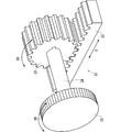
- FIG. 7 is a schematic configuration diagram of the rack 22 and the pinion 23.
- FIG. 8 is an operation explanatory diagram of the rack 22 and the pinion 23.
- the left-right position adjustment mechanism 20 includes a plurality of racks 22 and a plurality of pinions 23, but one rack 22 and one pinion 23 are shown in FIGS. 7 and 8. Since the horizontal position adjusting mechanism 20 and the vertical position adjusting mechanism 21 have the same configuration, only the horizontal position adjusting mechanism 20 will be described.
- the rack 22 is provided on the lower surface of the left-right movable table 16.
- the pinion 23 is disposed below the rack 22 and meshes with the rack 22.
- the left / right position adjustment knob 25 is connected to the pinion 23 via a connecting pin 24.
- the left / right position adjusting knob 25 is connected to a plurality of pinions 23 via a connecting pin 24.
- the left / right position adjustment knob 25 is disposed at a position facing the four corners of the LED base 5.
- FIG. 9 is an operation explanatory diagram of the position adjustment mechanism 50.
- the positioning pin 12 of the step adjustment mechanism 15 is inserted into the hole 19 a of the joint adjustment mechanism 10.
- the step adjustment member 14 is attracted to the contact portion 18 by magnetic force. Held in.
- the left / right position adjustment knob 25 of the left / right position adjustment mechanism 20 accessible from the bottom surface side of the LED base 5 in the XR direction
- the left / right position adjustment knob 25 is rotated as shown in FIGS. Is transmitted to the pinion 23 via the connecting pin 24. It is converted into a linear movement of the rack 22 of the left / right moving table 16 meshed with the pinion 23, and the left / right moving table 16 moves in the left / right direction.
- the up / down moving table 17 arranged on the left / right moving table 16 also moves in the left / right direction.
- the vertical position adjustment knob 26 of the vertical position adjustment mechanism 21 that can be accessed from the side surface side of the LED base 5 is rotated in the YR direction, so that it is transmitted to the pinion 23 via the connecting pin 24.
- the positioning pins 12 of the mechanism 15 simultaneously move up and down.
- the cylindrical portion 19 is moved in the vertical direction and the horizontal direction by the rotation operation of the horizontal position adjusting knob 25 accessible from the bottom surface side of the LED base 5 and the vertical position adjusting knob 26 accessible from the side surface side.
- the positioning pin 12 of the step adjustment mechanism 15 inserted in the position 19 moves in the vertical direction and the left and right direction. Of the four corners of the LED base 5 to which the step adjustment mechanism 15 is attached, The vertical and horizontal positions of the corners are adjusted.
- the joint adjustment mechanism 11 provided in the corner joint 9 at the lower right corner also rotates the left / right position adjustment knob 25 and the vertical position adjustment knob 26 to rotate the lower right corner of the LED base 5. The vertical and horizontal positions of are adjusted.
- the vertical and horizontal positions of the LED display tiles are adjusted by rotating the horizontal position adjustment knob 25 and the vertical position adjustment knob 26 provided at the corner joints 8 and 9 at the two corners.
- the gap which is the joint width between the LED display tile and the other adjacent LED display tiles, in the vertical direction and the horizontal direction can be adjusted.
- the operation portion 14a of the step adjustment member 14 attached to the four corners on the back surface of the LED base 5 the back surface of the LED base 5 and the contact portions of the joint adjustment mechanisms 10, 11 are provided. 18 and the abutting portion of the corner joints 6 and 7 can be adjusted. Thereby, the position of the four corners of the LED display tile 1 in the front-rear direction is adjusted.
- the joint adjusting mechanisms 10, 11 disposed at the position of the support structure 2, for example, facing the LED display tile 1 m, which serves as a position reference tile at the time of installation. Adjustment is performed by rotating the horizontal position adjustment knob 25 and the vertical position adjustment knob 26 so that the cylindrical portion 19 is positioned at the reference position in the vertical direction and the horizontal direction, respectively.
- the positioning pins 12 of the step adjusting mechanism 15 attached to the four corners on the back surface of the LED base 5 of the LED display tile 1m are connected to the joint adjusting mechanisms 10, 11 and the corner joints of the cone-shaped portions 27, respectively. It guides to the cylindrical part 19 which each comprises 6 and 7. At this time, the positioning pin 12 is guided while moving toward the center of the cylindrical portion 19, and the step adjustment member 14 is a contact portion made of a magnetic material of the contact portions 18 of the joint adjustment mechanisms 10 and 11 and the corner joints 6 and 7.
- the LED display tile 1m is held at the reference position in the vertical direction and the horizontal direction. Further, by rotating the operation portion 14a of the step adjusting member 14, the LED display tile 1m is adjusted to the reference position in the front-rear direction.
- the adjacent first-stage LED display tiles 1n, 1 GmbH, 1p, 1q, and 1r are sequentially adjusted with the joint adjustment mechanisms 10 and 11 in the same manner as described above.
- the mechanism 15 is installed while adjusting the position so that the joint width in the vertical direction and the horizontal direction and the step in the front-rear direction are not noticeable.
- the second-stage LED display tiles 1g, 1h, 1i, 1j, 1k, 1l, and the third-stage LED display tiles 1a, 1b, 1c, 1d, 1e, and 1f are similarly adjusted in the horizontal joint width. Install sequentially while adjusting the step in the front-rear direction.
- the multi-display system 100 having an 18-plane configuration has been described as an example.
- the same assembly adjustment can be performed.
- the joints on the display surface can be finely adjusted using the same adjustment procedure, making it possible for the joints between the LED display tiles to be inconspicuous and providing an image with a sense of unity. Become.
- the left / right moving table 16 and the up / down moving table 17 are moved in the left / right direction via the left / right position adjusting mechanism 20 by rotating the left / right position adjusting knob 25.
- the LED display tiles 1a to 1r are moved in the horizontal direction, and the LED display tiles 1a to 1r are moved by moving the vertical movement table 17 in the vertical direction via the vertical position adjustment mechanism 21 by rotating the vertical position adjustment knob 26.
- 1r moves up and down, and the positioning pin 12 in the state where the positioning pin 12 is inserted into the hole 19a is attracted to the contact portion 18 by the magnetic force of the magnet 13 so that each LED is
- the display tiles 1a to 1r are fixed to the support structure 2.
- the horizontal and vertical gaps of the display surface between the LED display tile and other adjacent LED display tiles and the step in the front-rear direction are accurately adjusted and fixed in that state, so that the quality of the image is improved. It is possible to improve.
- each LED display tile Even in an environment where it is difficult to access from the back side of 1a to 1r, the LED display tiles 1a to 1r can be pulled forward not only from the back side of each LED display tile 1a to 1r but also from the front side.
- the adjustment mechanisms 10 and 11 can be easily accessed. That is, the joint adjustment mechanisms 10 and 11 can be easily accessed from both the display surface side and the back surface side of the LED display tiles 1a to 1r.
- FIG. 10 is a schematic configuration diagram of a position adjustment mechanism 50A included in the multi-display system 100 according to the second embodiment.
- FIG. 11 is an explanatory diagram of the operation of the position adjustment mechanism 50A.
- the same components as those described in the first embodiment are denoted by the same reference numerals, and the description thereof is omitted.
- the shape of the positioning pin 12 is different from that in the first embodiment.
- the positioning pin 12 has a protrusion-shaped portion 28 provided at the distal end portion and a conical-shaped portion 27 provided on the proximal end side thereof.
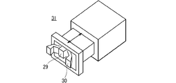
- the vertical movement table 17 further includes a latch mechanism 31 for fixing and releasing the protrusion-shaped portion 28 on the back side of the cylindrical portion 19.
- the latch mechanism 31 includes two claw portions 30 that can sandwich the protrusion-shaped portion 28 and a push-pull mechanism 29 that switches between opening and closing of the two claw portions 30.
- the two claw portions 30 are arranged on the left and right of the push / pull mechanism 29. Since the hole portion 19 a of the cylindrical portion 19 and the push / pull mechanism 29 are located on the same straight line, the protrusion-shaped portion 28 of the positioning pin 12 can perform a pushing operation on the push / pull mechanism 29.
- the two claw portions 30 are closed in conjunction with the pushing operation performed by the protrusion-shaped portion 28 of the positioning pin 12.
- the projection-shaped part 28 is fixed to the two claw parts 30, the play in the front-rear direction when the projection-shaped part 28 and the latch mechanism 31 are fitted can be eliminated.
- the push-pull mechanism 29 returns to the front, and the push-pull mechanism 29 returns to the front.
- the two claw portions 30 are opened. Thereby, fixation of the projection-shaped part 28 by the two nail
- FIG. 12 is a schematic configuration diagram of the lower right corner position adjustment mechanism 50B.
- the configuration is different between the lower left corner position adjustment mechanism 50A and the lower right corner position adjustment mechanism 50B.
- the vertical movement table 17 includes a long cylindrical portion 32 instead of the cylindrical portion 19.
- the long cylindrical portion 32 is arranged with a hole portion 32a, which is a long hole extending in the left-right direction, facing forward and backward.
- the position adjustment mechanism 50B at the lower right corner includes the long cylindrical portion 32, the position adjustment in the left and right direction of the LED display tiles 1a to 1r is mainly performed first in the left and right position adjustment knob 25 at the lower left corner.
- the positioning pin 12 of the position adjustment mechanism 50B at the lower right corner moves in the left-right direction in the hole 32a of the long cylindrical portion 32. Therefore, the long cylindrical portion 32 is not stressed, and the horizontal position of the LED display tiles 1a to 1r can be adjusted smoothly.
- the vertical position adjustment knob 26 and the step adjustment member 14 are adjusted in the same procedure, whereby the LED display tiles 1 a to 1 r are adjusted.
- the positions of the lower side in the vertical direction, the horizontal direction, and the front-rear direction are determined.
- FIG. 13 is a schematic configuration diagram of the corner joint 6 at the upper left corner.
- the corner joint 6 has a rectangular parallelepiped shape, and a contact portion 18 is disposed at the front end portion of the corner joint 6.
- a cylindrical portion 33 having a hole portion 33a into which the positioning pin 12 can be fitted is disposed at the front portion in the corner joint 6.
- the hole 33 a of the cylindrical portion 33 has a diameter larger than that of the hole 19 a of the cylindrical portion 19. This is because the part size and the mounting variation of the LED base 5 are taken into consideration.
- the joint adjusting mechanisms 10 and 11 can be omitted, and the member cost can be reduced.
- the corner joint 6 further includes a latch mechanism 31 on the back side of the cylindrical portion 33. Note that the corner joint 7 at the upper right corner is left-right symmetric with respect to the corner joint 6 at the upper left corner shown in FIG.
- the positioning pin 12 has the protrusion-shaped portion 28 provided at the distal end portion, and the up-and-down moving base 17 is located behind the hole portions 19a and 32a.
- the latch mechanism 31 further includes a latch mechanism 31 that fixes and releases the protrusion-shaped portion 28.
- the latch mechanism 31 includes a claw portion 30 that can hold the protrusion-shaped portion 28, and a push-pull mechanism 29 that switches between opening and closing the claw portion 30.
- the LED display tiles 1a to 1r are fixed to and released from the support structure 2 by fixing and releasing the protrusions 28 by pushing the step adjustment mechanism 15 with respect to the push / pull mechanism 29.
- the projection-shaped portion 28 can be held by the claw portion 30, so that the LED display tiles 1 a to 1 r and the support structure 2 can be held. The fixed state is maintained.
- the latch mechanism 31 has been described as including two claw portions 30, but is not limited thereto, and includes three or more claw portions 30. Also good.
- FIG. 14 is a schematic configuration diagram of the latch mechanism 31.
- FIG. 15 is a schematic configuration diagram of another example of the latch mechanism 31.
- the six claw portions 30 are arranged at equal intervals around the push-pull mechanism, and can be sandwiched so as to firmly wrap the projection-shaped portion 28.
- the projection-shaped portion 28 can be strongly held by the six claw portions 30, so even if a strong external force is applied due to an earthquake or the like The fixed state between the LED display tiles 1a to 1r and the support structure 2 is maintained.
- FIG. 16 is a schematic configuration diagram of a position adjustment mechanism 50C included in the multi-display system 100 according to the third embodiment.
- FIG. 17 is an explanatory diagram of the operation of the position adjustment mechanism 50C.
- the same components as those described in the first and second embodiments are denoted by the same reference numerals, and the description thereof is omitted.
- the joint adjustment mechanism 10 ⁇ / b> A further includes a back-and-forth moving table 34.
- the front / rear moving table 34 includes a bottom surface portion 34a and a left side surface portion 34b, and is L-shaped in a front view.
- the back-and-forth moving base 34 is disposed on the corner joint 8.
- One slide portion 35 extending in the front-rear direction is provided on each of the bottom surface portion 34a and the left side surface portion 34b, and a groove portion (not shown) is provided at a position corresponding to the slide portion 35 on the bottom surface portion 8a and the left side surface portion 8b of the corner joint 8.
- the front / rear moving table 34 can move on the corner joint 8 in the front / rear direction.
- the left / right moving table 16 is disposed on the front / rear moving table 34 and is movable in the left / right direction on the front / rear moving table 34.
- the front / rear moving table 34 When the LED display tiles 1a to 1r are fixed to the support structure 2, the front / rear moving table 34 is moved forward, the positioning pin 12 is inserted into the hole 19a, and the surface on the positioning pin 12 side of the step adjustment member 14 In the state where the magnet 13 is attracted to the contact portion 18 by the magnetic force of the magnet 13, the front / rear moving table 34 is moved backward. As a result, the position adjustment mechanism 50C can be accessed in a state where the LED display tiles 1a to 1r are moved forward by the forward / backward movement table 34, so that the position adjustment mechanism 50C can be easily accessed.
- a stopper 36 is provided at the front end portion of the left side surface portion 8b of the corner joint 8
- a hooking portion 37 is provided at the rear end portion of the left side surface portion 34b of the front / rear moving table 34.
- the front / rear moving table 34 is moved forward to be positioned in the hole 19a.
- the pin 12 is inserted, and the back-and-forth moving table 34 is moved backward in a state where the surface on the positioning pin 12 side of the step adjustment member 14 is attracted to the contact portion 18 by the magnetic force of the magnet 13.
- the position adjustment mechanism 50C can be accessed in a state where the LED display tiles 1a to 1r are moved forward by the forward / backward movement table 34, so that the position adjustment mechanism 50C can be easily accessed.
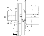
- FIG. 18 is a diagram for explaining the operation of position adjustment in the front-rear direction of the step adjustment mechanism 15 and the joint adjustment mechanism 10A in the left-right direction and up-down direction by the magnet jig 300 provided in the multi-display system 100 according to the fourth embodiment.
- the same components as those described in the first to third embodiments are denoted by the same reference numerals and description thereof is omitted.
- the multi-display system 100 further includes a magnet jig 300.
- the magnet jig 300 is disposed at a position corresponding to the position adjustment mechanism 10A on the back side of the display surface of the LED display tile 1a.
- the magnet jig 300 includes a protective resin layer 301 that has been subjected to antistatic treatment, and magnet rotating portions 302, 320, and 321 that can rotate with respect to the protective resin layer 301.
- a case where the magnet jig 300 is employed in the multi-display system 100 according to the second embodiment will be described.
- the protective resin layer 301 of the magnet jig 300 is brought into contact with the display surface of the LED display tile 1a and is placed on the LED base 5 on the back side of the LED display tile 1a.
- the magnet rotating part 302 is rotated in a state where the magnet 13 and the magnet rotating part 302 in the stepped adjustment member 14 screwed together are attracted by magnetic force.
- the magnet rotation unit 320 When adjusting the position of the LED display tile 1a in the left-right direction, the magnet rotation unit 320 is rotated while the left-right position adjustment knob 25 on the back side of the LED display tile 1a and the magnet rotation unit 320 are attracted by magnetic force. .
- the magnet rotation unit 321 When adjusting the vertical position of the LED display tile 1a, the magnet rotation unit 321 is rotated with the vertical position adjustment knob 26 on the back side of the LED display tile 1a and the magnet rotation unit 321 adsorbed by magnetic force. .
- FIG. 19 is an explanatory view of the operation of adjusting the position of the step adjustment mechanism 15A in the forward direction by the magnet jig 300.
- FIG. 20 is an explanatory diagram of the operation of adjusting the position in the rear direction of the step adjustment mechanism 15A by the magnet jig 300.
- FIG. 19 is an explanatory view of the operation of adjusting the position of the step adjustment mechanism 15A in the forward direction by the magnet jig 300.
- FIG. 20 is an explanatory diagram of the operation of adjusting the position in the rear direction of the step adjustment mechanism 15A by the magnet jig 300.
- the step adjustment member screwed onto the LED base 5 on the back side of the LED display tile 1a by bringing the protective resin layer 301 of the magnet jig 300 into contact with the display surface of the LED display tile 1a. 14, the magnet rotating unit 302 is rotated clockwise around the rotating shaft 303 in a state where the magnet 13 and the magnet rotating unit 302 are attracted by a magnetic force. Then, since the step adjustment member 14 rotates in the extending direction, the step adjustment member 14 moves relatively to the opposite side of the LED display tile 1a, and the distance between the contact portion 18 and the LED display tile 1a becomes longer. The LED display tile 1a moves forward.
- the step adjustment member screwed onto the LED base 5 on the back side of the LED display tile 1a by bringing the protective resin layer 301 of the magnet jig 300 into contact with the display surface of the LED display tile 1a. 14, the magnet rotating unit 302 is rotated counterclockwise about the rotating shaft 303 in a state where the magnet 13 and the magnet rotating unit 302 are attracted by magnetic force. Then, since the step adjustment member 14 rotates in the tightening direction, the step adjustment member 14 moves relatively to the LED display tile 1a side, and the distance between the contact portion 18 and the LED display tile 1a is shortened. The display tile 1a moves backward.
- the magnet jig 300 can be rotated from the front side of the LED display tiles 1a to 1r even when the multi-display system 100 is assembled and there is no work space on the back side. By performing the operation, it is possible to adjust so as to eliminate the step in the front-rear direction between the LED display tile and another adjacent LED display tile.
- the LED display tile and the other LED display tiles adjacent to the LED display tile in the horizontal direction and the vertical direction It is possible to adjust so as to eliminate the gap in the direction.
- the left / right position adjustment knob 25 and the vertical position adjustment knob 26 both have magnets
- the multi-display system 100 includes the step adjustment member 14, the left / right position adjustment knob. 25 and the vertical position adjustment knob 26 are further provided, and the magnet jig 300 is disposed on the display surfaces of the LED display tiles 1a to 1r, and the display surfaces of the LED display tiles 1a to 1r.
- Each LED display is operated by rotating the step adjustment member 14, the left / right position adjustment knob 25 and the vertical position adjustment knob 26 through the LED display tiles 1a to 1r by the magnetic force of the magnet jig 300 from the side.
- the positions of the tiles 1a to 1r in the front-rear direction, the left-right direction, and the up-down direction are adjusted.
- the front-rear direction, the left-right direction, and the right-and-left direction of each of the LED display tiles 1a to 1r can be performed by rotating the magnetic force without directly rotating the step adjustment member 14, the left-right position adjustment knob 25, and the vertical position adjustment knob 26 manually. It is possible to individually adjust the vertical position.
- the joints and steps between the LED display tiles and other adjacent LED display tiles can be accurately detected from the front side by the magnet jig 300. It becomes possible to adjust well.
- the magnet jig 300 is used in the multi-display system 100 according to the second embodiment.
- the magnet jig 300 is used in the multi-display system 100 according to the first and third embodiments. It is also possible to adopt. Also in this case, the same effect as in the fourth embodiment can be obtained.
Landscapes
- Engineering & Computer Science (AREA)
- Physics & Mathematics (AREA)
- General Physics & Mathematics (AREA)
- Theoretical Computer Science (AREA)
- Microelectronics & Electronic Packaging (AREA)
- General Engineering & Computer Science (AREA)
- Multimedia (AREA)
- Devices For Indicating Variable Information By Combining Individual Elements (AREA)
- Mechanical Engineering (AREA)
Abstract
映像表示装置の表示面側および背面側の両方向から容易にアクセスすることが可能であり、かつ、映像表示装置と隣接する他の映像表示装置との間の表示面の左右方向および上下方向の隙間と前後方向の段差とを精度よく調整しその状態で固定することで、映像の品位を向上させることが可能な技術を提供することを目的とする。左右位置調整ノブ25の回転操作により各LED表示タイル1a~1rが左右方向に移動する。上下位置調整ノブ26の回転操作により各LED表示タイル1a~1rが上下方向に移動する。位置決めピン12が穴部19aに挿入された状態で段差調整部材14における位置決めピン12側の面が磁石13の磁力により当接部18に吸着することで、各LED表示タイル1a~1rが支持構造体2に固定される。
Description
本発明は、複数の映像表示装置を上下方向および左右方向に並べて大画面の映像情報を表示するマルチディスプレイシステムおよび映像表示装置に関するものである。
LEDなどの表示素子を複数用いて構成される表示タイルは、表示素子の技術発展と低コスト化のおかげで、屋外および屋内の広告表示等に多く使用されている。表示タイルを備える表示装置は、これまで自然画およびアニメーションの動画像の表示等に用いられることが主流であった。しかし、屋内用途として、画素ピッチの狭ピッチ化に伴い視認距離が短くなることから、表示タイルを備える表示装置は、会議室および監視用途などのパソコンの画像表示用にも近年使用されるようになってきた。特に、監視用途においては、静止画に近いパソコン画像を表示することが多くなっている。
また、表示タイルを備える表示装置としては、セラミックまたは樹脂などで成型されたキャビティの内部にLED表示素子を実装し、これを封止樹脂で固めることで形成された小さなLED表示モジュールを基板に実装したSMD(Surface Mount Device:表面実装部品)型が主流である。SMD型の表示装置は、これまで画素ピッチが3mm以上の大型映像表示装置として使用されてきた。
しかし、近年では、LED表示素子の低コスト化と高精細化を背景に、画素ピッチが1~2mm等の高密度実装品にて構成されたLED表示装置をタイル状に複数並べて構成した大型映像表示装置が市場に導入されている。
例えば特許文献1および特許文献2には、LED表示装置の構成要素とその保持方法が開示されている。
特許文献1では、大型映像表示装置は、複数のLED表示タイルから構成されたマルチディスプレイシステムにより構成されている。小さなLED表示モジュール基板上に、R,G,BのLED表示素子がモジュール基板の周縁部の近傍まで実装されている。複数のLED表示モジュール基板が正方配列状に配置されて第1のLED表示タイルを形成するために、複数のLED表示モジュール基板がサポート構造に組み立てられている。第2のLED表示タイルも、第1のLED表示タイルと同様にサポート構造に組み立てられている。第1のLED表示タイルと第2のLED表示タイルは、非常に小さな隙間を維持して互いにほぼ密着した状態でサポート構造に組み立てられている。この非常に小さな隙間に対して、画素ピッチと同じ寸法が要求されている。
また、特許文献1および特許文献2には、LED表示タイルの側面の形状は平面形状に加工されている。これらのLED表示タイルを複数組み合わせて、マルチディスプレイシステムによる大画面映像表示装置を構成する場合、各LED表示タイルの側面がほぼ密着するように連結される。
また、特許文献3には、フック型の連結部材を用いてLED表示タイル同士を連結する構造が開示されている。
LED表示タイルと隣接する他のLED表示タイルとの上下方向および左右方向の隙間、およびLED表示面の前後方向の段差を画素ピッチと同じ寸法に抑えて、これらの隙間および段差が目立たないようにすることが必要となる。また、映像表示装置の背面側に作業するための十分な空間がないため、映像表示面側からこれらの隙間および段差が目立たないように映像表示装置の位置を調整することも必要となる。
特許文献1では、各LED表示タイルはその配列が損なわれることがないように取付け構造体により支持されている。この取付け構造体は、LED表示タイルと、上下方向および左右方向に隣接するLED表示タイルとの隙間が画素ピッチと同じ寸法になるように配置されている。しかし、LED表示タイルの側面は平面に形成されているため、LED表示タイルを保持するサポート構造の寸法公差または平面度等の機械的な精度に起因して、LED表示タイルと隣接する他のLED表示タイルとの隙間がばらつくという問題があった。
また、特許文献2では、LED表示モジュール基板がLEDベース部品に取り付けられ、LEDベース部品の背面に筐体フレーム部品とジョイント部品が取り付けられている。そして、これらの部材から構成されたLED表示タイルは、ほぼ平面形状の側面を有している。特許文献2においても、特許文献1の場合と同様に、LED表示タイルを上下方向および左右方向に複数配置した場合、LED表示タイルと隣接する他のLED表示タイルとの隙間がばらつくという問題があった。
また、特許文献3では、フック型の連結部材を用いてLED表示タイル同士を連結しているため、LED表示タイル同士の左右方向の連結に際して高精度な位置合わせが必要である。そのため、LED表示タイルの位置合わせに相当な時間を要するという問題があった。
このように特許文献1~3に記載の構造では、LED表示タイルを構成する金属筐体の構造部品の加工寸法のバラツキ、またはLED表示モジュール基板のソリ等によって、LED表示タイルと隣接する他のLED表示タイルとの隙間およびLED表示面の前後方向の段差が発生するという問題があった。このような隙間および段差は、輝度の変化または指向性の変化などにより、連結部、すなわち、LED表示タイルと隣接する他のLED表示タイルとの間の目地として認識され、映像の品位が劣化する要因となっていた。
そこで、本発明は、映像表示装置の表示面側および背面側の両方向から容易にアクセスすることが可能であり、かつ、映像表示装置と隣接する他の映像表示装置との間の表示面の左右方向および上下方向の隙間と前後方向の段差とを精度よく調整しその状態で固定することで、映像の品位を向上させることが可能な技術を提供することを目的とする。
本発明に係るマルチディスプレイシステムは、複数の映像表示装置と、複数の前記映像表示装置を支持する支持構造体と、各前記映像表示装置の位置を調整可能な位置調整機構とを備え、前記位置調整機構は、各前記映像表示装置の上下方向および左右方向の位置調整を担う目地調整機構と、各前記映像表示装置の前後方向の位置調整を担う段差調整機構とを備え、前記段差調整機構は、各前記映像表示装置の背面の4つの角部に配置されかつ磁石を有する、回転操作可能な段差調整部材と、前記段差調整部材の回転軸と同軸上に設けられた位置決めピンとを備え、前記目地調整機構は、前記支持構造体における各前記映像表示装置の4つの角部に対応する位置に配置された連結部材と、前記連結部材上を左右方向に移動可能な左右移動台と、前記左右移動台上を上下方向に移動可能な上下移動台と、前記上下移動台の前端部に配置されかつ磁石または磁性体材料により形成され前記段差調整部材における前記位置決めピン側の面と当接可能な当接部と、前記当接部から後方に延びるように形成されかつ前記位置決めピンを挿入可能な穴部と、前記左右移動台および前記上下移動台を左右方向に移動させる左右位置調整機構と、前記左右位置調整機構に連結されかつ前記連結部材に配置された、回転操作可能な左右位置調整ノブと、前記上下移動台を上下方向に移動させる上下位置調整機構と、前記上下位置調整機構に連結されかつ前記左右移動台に配置された、回転操作可能な上下位置調整ノブとを備え、前記左右位置調整ノブの回転操作により前記左右位置調整機構を介して前記左右移動台および前記上下移動台を左右方向に移動させることで各前記映像表示装置が左右方向に移動し、前記上下位置調整ノブの回転操作により前記上下位置調整機構を介して前記上下移動台を上下方向に移動させることで各前記映像表示装置が上下方向に移動し、前記位置決めピンが前記穴部に挿入された状態で前記段差調整部材における前記位置決めピン側の面が前記磁石の磁力により前記当接部に吸着することで、各前記映像表示装置が前記支持構造体に固定される。
本発明によれば、映像表示装置の表示面側および背面側の両方向から容易にアクセスすることが可能であり、かつ、映像表示装置と隣接する他の映像表示装置との間の表示面の左右方向および上下方向の隙間と前後方向の段差とを精度よく調整しその状態で固定することで、映像の品位を向上させることが可能である。
この発明の目的、特徴、局面、および利点は、以下の詳細な説明と添付図面とによって、より明白となる。
<実施の形態1>
本発明の実施の形態1について、図面を用いて以下に説明する。図1は、実施の形態1に係るマルチディスプレイシステム100の斜視図である。図2は、LED表示タイル1fの斜視図である。図3は、LED表示タイル1fおよび支持構造体2の分解斜視図である。
本発明の実施の形態1について、図面を用いて以下に説明する。図1は、実施の形態1に係るマルチディスプレイシステム100の斜視図である。図2は、LED表示タイル1fの斜視図である。図3は、LED表示タイル1fおよび支持構造体2の分解斜視図である。
図1に示すように、マルチディスプレイシステム100は、複数のLED表示タイル1a~1r、支持構造体2、および架台3を備えている。なお、LED表示タイル1a~1rが映像表示装置に相当する。
また、マルチディスプレイシステム100はさらに、位置調整機構50(図6参照)を備えている。
マルチディスプレイシステム100は、架台3に、例えば18台のLED表示タイル1a~1rを上下方向および左右方向に配置して構成されている。より具体的には、LED表示タイル1a~1rは、上下方向に3台、左右方向に6台配置されている。18台のLED表示タイル1a~1rは同じ構成であるため、ここではLED表示タイル1fについて説明する。
図2に示すように、LED表示タイル1fは、4枚のLEDモジュール基板4、およびLEDベース5を備えている。4枚のLEDモジュール基板4は、上下方向に2枚、左右方向に2枚配置されている。4枚のLEDモジュール基板4の各々には、表示素子としてのLEDが正方配列状に複数配列されている。LEDベース5は、4枚のLEDモジュール基板4の背面に固定されている。LEDベース5は、非磁性材料であるアルミニウムまたはマグネシウム合金を用いて構成されている。4枚のLEDモジュール基板4は、LEDベース5に対して精度よく位置調整され、LEDモジュール基板4と隣接する他のLEDモジュール基板4との間の隙間が目立たないように配置され固定されている。
図2と図3に示すように、支持構造体2は、LED表示タイル1fの背面、より具体的には、LEDベース5の背面にコーナージョイント6,7,8,9を介して連結され、LED表示タイル1fの背面を支持する。支持構造体2は、非磁性材料であるアルミニウムを用いて構成されている。コーナージョイント6,7,8,9は、LED表示タイル1fの背面の4つの角部に対応する位置に配置されている。支持構造体2は、矩形枠形状の2つの背面フレーム102,103を前後に組み付けて構成されている。背面フレーム102および背面フレーム103は、前後方向に延びる複数のフレーム102cにより固定されている。フレーム102cは、コーナージョイント6,7,8,9の周辺に配置されている。なお、前後方向とは図1の「Z軸方向」である。また、コーナージョイント6,7,8,9が連結部材に相当する。
次に、背面フレーム102について説明する。図3に示すように、背面フレーム102は、前側のフレームであり、左右方向に延びるフレーム102a、および上下方向に延びるフレーム102bを備えている。なお、左右方向とは図1の「X軸方向」であり、上下方向とは図1の「Y軸方向」である。
次に、背面フレーム103について説明する。背面フレーム103は、後側のフレームであり、左右方向に延びるフレーム103a、および上下方向に延びるフレーム103bを備えている。
また、LED表示タイル1a~1rの背面を構成するLEDベース5の内部には、LED表示駆動回路および電源などが収容されているが、これらは従来の構成と同様であるためその詳細については説明を省略する。
図3に示すように、コーナージョイント6,7,8,9が背面フレーム102および背面フレーム103を連結するフレーム102eに固定ネジ(図示省略)により固定されることで、支持構造体2を構成するフレーム同士は強固に連結されている。フレーム102a,102b,102c,202a,202bは、断面形状が同一で長さが異なる押出フレームである。支持構造体2は、複数の押出フレームを組み合わせることで安価に構成することが可能である。
コーナージョイント6,7,8,9は、支持構造体2におけるLED表示タイル1fの4つの角部に対応する位置に配置されている。より具体的には、コーナージョイント6は、支持構造体2におけるLED表示タイル1fの左上の角部に対応する位置に配置されている。コーナージョイント7は、支持構造体2におけるLED表示タイル1fの右上の角部に対応する位置に配置されている。コーナージョイント8は、支持構造体2におけるLED表示タイル1fの左下の角部に対応する位置に配置されている。コーナージョイント9は、支持構造体2におけるLED表示タイル1fの右下の角部に対応する位置に配置されている。
本実施の形態では、コーナージョイント8に、位置調整機構50の一部である目地調整機構10が設けられ、コーナージョイント9に、位置調整機構50の一部である目地調整機構11が設けられている。コーナージョイント8,9は、フレーム連結の役割と、支持構造体2の強度メンバーとしての役割と、LED表示タイル1fの上下方向および左右方向の位置調整機能とを兼ね備えており、部品点数の削減、および製造コストの削減が図られている。なお、本実施の形態では、コーナージョイント8,9に目地調整機構10,11がそれぞれ設けられているが、コーナージョイント8,9に代えてコーナージョイント6,7に目地調整機構がそれぞれ設けられていてもよい。
次に、LED表示タイル1a~1rの背面構造について説明する。図4は、LED表示タイル1aの背面斜視図である。図5は、段差調整機構15の斜視図である。18台のLED表示タイル1a~1rは同じ構成であるため、ここではLED表示タイル1aについて説明する。
図4に示すように、LEDベース5の背面の4つの角部に、4つの段差調整機構15がそれぞれ設けられている。段差調整機構15は、位置調整機構50の一部である。ここで、位置調整機構50について簡単に説明する。
位置調整機構50は、各LED表示タイル1a~1rの位置を調整可能であり、目地調整機構10,11、および段差調整機構15を備えている。目地調整機構10,11は、各LED表示タイル1a~1rの左右方向および上下方向の位置調整を担っている。段差調整機構15は、各LED表示タイル1a~1rの前後方向の位置調整を担っている。
図4と図5に示すように、段差調整機構15は、段差調整部材14、磁石13、および位置決めピン12を備えている。段差調整部材14は円板形状であり、段差調整部材14の外周部に操作部14aが設けられている。操作部14aは、使用者が指でつまんで段差調整部材14を回転させるために設けられている。段差調整部材14の前面に、前方に突出する雄ネジ14bが設けられている。段差調整部材14の背面に位置決めピン12が設けられている。位置決めピン12は段差調整部材14の中心軸上に背面から後方に突出している。すなわち、位置決めピン12は段差調整部材14の回転軸と同軸上に設けられている。また、位置決めピン12は先端部に設けられた円錐形状部27を有している。
LEDベース5の背面の4つの角部に4つのネジ穴(図示省略)がそれぞれ設けられ、4つの段差調整機構15は、LEDベース5の背面のネジ穴に雄ネジ14bが螺合することでLEDベース5の背面にそれぞれ取り付けられている。4つの段差調整機構15が備える段差調整部材14には磁石13が内蔵されている。このように、4つの段差調整機構15は、LEDベース5の背面の4つの角部に取り付けられているため、LEDベース5の各側面からアクセス可能である。
次に、LED表示タイル1aの支持構造体2への取り付け方法について説明する。図6は、位置調整機構50の概略構成図である。ここで、右下の角部のコーナージョイント9に設けられる目地調整機構10は、左下の角部のコーナージョイント8に設けられる目地調整機構10の左右対称であるため、左下の角部のコーナージョイント8に設けられる目地調整機構10のみ説明する。
図6に示すように、目地調整機構10は、コーナージョイント8、左右移動台16、上下移動台17、当接部18、穴部19a、左右位置調整機構20、回転操作可能な左右位置調整ノブ25、上下位置調整機構21、および回転操作可能な上下位置調整ノブ26を備えている。
コーナージョイント8は、底面部8aおよび左側面部8bを備え、正面視にてL字状である。左右移動台16は、底面部16aおよび左側面部16bを備え、正面視にてL字状である。左右移動台16は、コーナージョイント8上に配置され、コーナージョイント8上を左右方向に移動可能である。左右移動台16には左右位置調整機構20が設けられており、左右移動台16の下面には、左右位置調整機構20の一部である左右方向に延びる複数のラック22が設けられている。
上下移動台17は、直方体状であり、左右移動台16上に配置され、左右移動台16上を上下方向に移動可能である。上下移動台17の前端部に当接部18が配置されている。当接部18は、磁石または磁性体材料により形成され段差調整部材14における位置決めピン12側の面と当接可能である。上下移動台17内の前部には、位置決めピン12が挿入可能な穴部19aを有する円筒部19が配置されている。より具体的には、円筒部19は穴部19aを前後に向けた状態で配置されており、穴部19aは当接部18から後方に延びている。上下移動台17には上下位置調整機構21が設けられている。上下移動台17の左側面には、上下位置調整機構21の一部である上下方向に延びる複数のラック22が設けられている。
左右位置調整ノブ25は、左右位置調整機構20に連結され、かつ、コーナージョイント8に取り付けられている。上下位置調整ノブ26は、上下位置調整機構21に連結され、かつ、左右移動台16に取り付けられている。また、左右位置調整ノブ25および上下位置調整ノブ26には磁石が内蔵されている。
次に、図7と図8を用いて、左右位置調整機構20および上下位置調整機構21について説明する。図7は、ラック22およびピニオン23の概略構成図である。図8は、ラック22およびピニオン23の動作説明図である。なお、左右位置調整機構20は、複数のラック22および複数のピニオン23を備えているが、図7と図8では1つのラック22および1つのピニオン23が示されている。左右位置調整機構20および上下位置調整機構21は同じ構成であるため、左右位置調整機構20についてのみ説明する。
図6~図8に示すように、ラック22は左右移動台16の下面に設けられている。ピニオン23はラック22の下側に配置され、ラック22に噛合している。左右位置調整ノブ25は、連結ピン24を介してピニオン23に連結されている。実際には、左右位置調整ノブ25は、連結ピン24を介して複数のピニオン23に連結されている。また、左右位置調整ノブ25は、LEDベース5の4つの角部に対向する位置に配置されている。左右位置調整ノブ25をXR方向に回転させることにより、連結ピン24を介して連結されたピニオン23が回転し、ピニオン23と噛合しているラック22が左右方向に水平移動する。
図9は、位置調整機構50の動作説明図である。図9に示すように、目地調整機構10の穴部19aに段差調整機構15の位置決めピン12が挿入されている。このとき、磁石13を内蔵した段差調整部材14に設けられた位置決めピン12が目地調整機構10の穴部19aに案内された後、段差調整部材14は磁力により当接部18に吸着された状態で保持される。
次に、LEDベース5の底面側からアクセスできる左右位置調整機構20の左右位置調整ノブ25をXR方向に回転操作することにより、図7と図8で示すように、左右位置調整ノブ25の回転が連結ピン24を介してピニオン23に伝達される。ピニオン23に噛合している左右移動台16のラック22の直線移動に変換され、左右移動台16が左右方向に移動する。同時に、左右移動台16上に配置されている上下移動台17も左右方向に移動する。
次に、LEDベース5の側面側からアクセスできる上下位置調整機構21の上下位置調整ノブ26をYR方向に回転操作することにより、連結ピン24を介してピニオン23に伝達される。ピニオン23に噛合している上下移動台17のラック22の直線移動に変換され、上下移動台17が上下方向に移動し、上下移動台17に設けられた円筒部19に挿入されている段差調整機構15の位置決めピン12が同時に上下方向に移動する。
以上のように、LEDベース5の底面側からアクセスできる左右位置調整ノブ25および側面側からアクセスできる上下位置調整ノブ26の回転操作により、円筒部19は上下方向および左右方向に移動し、円筒部19に挿入されている段差調整機構15の位置決めピン12が上下方向および左右方向に移動することになり、段差調整機構15が取り付けられているLEDベース5の4つの角部のうち、まずは、左下の角部の上下方向および左右方向の位置が調整される。
これと同様に、右下の角部のコーナージョイント9に設けられた目地調整機構11についても、左右位置調整ノブ25および上下位置調整ノブ26の回転操作により、LEDベース5の右下の角部の上下方向および左右方向の位置が調整される。
以上のように、2つの角部のコーナージョイント8,9に設けられた左右位置調整ノブ25および上下位置調整ノブ26の回転操作により、LED表示タイルの上下方向および左右方向の位置を調整することが可能となり、LED表示タイルと隣接する他のLED表示タイルとの間の上下方向および左右方向の目地幅である隙間を調整することができる。
また、LEDベース5の背面の4つの角部に取り付けられている段差調整部材14の操作部14aを回転操作することにより、LEDベース5の背面と、目地調整機構10,11それぞれの当接部18およびコーナージョイント6,7の当接部との間隔を調整することができる。これにより、LED表示タイル1の4つの角部の前後方向の位置が調整される。
次に、マルチディスプレイシステム100を構成するLED表示タイル1a~1rの設置方法について説明する。図1と図3と図9に示すように、まず、設置の際の位置基準タイルとなる、例えばLED表示タイル1mに対向する支持構造体2の位置に配置された目地調整機構10,11の円筒部19がそれぞれ、上下方向および左右方向の基準位置に位置するように、左右位置調整ノブ25および上下位置調整ノブ26を回転操作することにより調整する。
次に、LED表示タイル1mのLEDベース5の背面の4つの角部に取り付けられた段差調整機構15の位置決めピン12を、その円錐形状部27それぞれが目地調整機構10、11、および、コーナージョイント6,7それぞれに具備している円筒部19に案内する。このとき、位置決めピン12は円筒部19の中心方向に寄りながら案内され、段差調整部材14が目地調整機構10,11の当接部18およびコーナージョイント6,7の磁性体材料からなる当接部に磁力により吸着され、LED表示タイル1mは上下方向および左右方向の基準位置に保持される。また、段差調整部材14の操作部14aを回転操作することにより、LED表示タイル1mは前後方向の基準位置に調整される。
位置基準タイルとなるLED表示タイル1mを設置した後、隣接する1段目のLED表示タイル1n,1о,1p,1q,1rを順次、上記と同様の方法で目地調整機構10,11と段差調整機構15について、上下方向および左右方向の目地幅と前後方向の段差が目立たないように位置を調整しながら設置する。さらに、2段目のLED表示タイル1g,1h,1i,1j,1k,1l、3段目のLED表示タイル1a,1b,1c,1d,1e,1fも同様に左右方向の目地幅の調整と前後方向の段差の調整を実施しながら順次設置する。
なお、実施の形態では、18面構成のマルチディスプレイシステム100を例として説明したがさらに多数のLED表示タイルを備えるマルチディスプレイシステムの場合にも、これと同様の組立調整を行うことが可能である。マルチディスプレイシステムが大型であっても、これと同様の調整手順で表示面の目地を微細に調整できるため、LED表示タイル間の目地が目立ちにくく、一体感のある映像を提供することが可能となる。
以上のように、実施の形態1に係るマルチディスプレイシステム100では、左右位置調整ノブ25の回転操作により左右位置調整機構20を介して左右移動台16および上下移動台17を左右方向に移動させることで各LED表示タイル1a~1rが左右方向に移動し、上下位置調整ノブ26の回転操作により上下位置調整機構21を介して上下移動台17を上下方向に移動させることで各LED表示タイル1a~1rが上下方向に移動し、位置決めピン12が穴部19aに挿入された状態で段差調整部材14における位置決めピン12側の面が磁石13の磁力により当接部18に吸着することで、各LED表示タイル1a~1rが支持構造体2に固定される。
したがって、LED表示タイルと隣接する他のLED表示タイルとの間の表示面の左右方向および上下方向の隙間と前後方向の段差とを精度よく調整しその状態で固定することで、映像の品位を向上させることが可能である。
左右位置調整ノブ25および上下位置調整ノブ26は、支持構造体2における各LED表示タイル1a~1rの角部に対応する位置に配置されたコーナージョイント8,9に設けられたため、各LED表示タイル1a~1rの背面側からアクセスしにくい環境においても、各LED表示タイル1a~1rの背面側からのみならず、正面側からでも、各LED表示タイル1a~1rを前方向に引き出すことで、目地調整機構10,11に容易にアクセスすることが可能である。すなわち、LED表示タイル1a~1rの表示面側および背面側の両方向から目地調整機構10,11に容易にアクセスすることが可能である。
<実施の形態2>
次に、実施の形態2に係るマルチディスプレイシステム100について説明する。図10は、実施の形態2に係るマルチディスプレイシステム100が備える位置調整機構50Aの概略構成図である。図11は、位置調整機構50Aの動作説明図である。なお、実施の形態2において、実施の形態1で説明したものと同一の構成要素については同一符号を付して説明は省略する。
次に、実施の形態2に係るマルチディスプレイシステム100について説明する。図10は、実施の形態2に係るマルチディスプレイシステム100が備える位置調整機構50Aの概略構成図である。図11は、位置調整機構50Aの動作説明図である。なお、実施の形態2において、実施の形態1で説明したものと同一の構成要素については同一符号を付して説明は省略する。
図10と図11に示すように、実施の形態2では、実施の形態1の場合と位置決めピン12の形状が異なっている。具体的には、位置決めピン12は、先端部に設けられた突起形状部28と、その基端側に設けられた円錐形状部27とを有している。
さらに、上下移動台17は、円筒部19の奥側に突起形状部28の固定および固定解除を行うラッチ機構31をさらに備えている。ラッチ機構31は、突起形状部28を挟持可能な2つの爪部30と、2つの爪部30の開閉を切り替えるプッシュ・プル機構29とを備えている。2つの爪部30は、プッシュ・プル機構29の左右に配置されている。円筒部19の穴部19aとプッシュ・プル機構29は同一直線上に位置しているため、位置決めピン12の突起形状部28はプッシュ・プル機構29に対する押し込み操作を行うことが可能である。
図11に示すように、プッシュ・プル機構29は、位置決めピン12の突起形状部28により行われた押し込み操作に連動して2つの爪部30が閉まる。これにより、突起形状部28が2つの爪部30に固定されることから、突起形状部28とラッチ機構31の嵌合時の前後方向の遊びを解消することができる。また、図10に示すように、位置決めピン12の突起形状部28により、さらに深い押し込み操作が行われた場合、プッシュ・プル機構29は前方に戻り、プッシュ・プル機構29が前方に戻ることに連動して2つの爪部30が開く。これにより、2つの爪部30による突起形状部28の固定が解除される。
次に、右下の角部のコーナージョイント9に設けられた位置調整機構50Bについて説明する。図12は、右下の角部の位置調整機構50Bの概略構成図である。
実施の形態2では、左下の角部の位置調整機構50Aと右下の角部の位置調整機構50Bとで構成が異なっている。図12に示すように、上下移動台17は円筒部19に代えて、長円筒部32を備えている。長円筒部32は、左右方向に延びる長穴である穴部32aを前後に向けた状態で配置されている。
右下の角部の位置調整機構50Bが長円筒部32を備えることで、LED表示タイル1a~1rの左右方向の位置調整は、主として、最初に実施する左下の角部の左右位置調整ノブ25の回転操作によりLED表示タイル1a~1rの左右方向の位置を調整する際に、右下の角部の位置調整機構50Bの位置決めピン12が長円筒部32の穴部32a内を左右方向に移動できるため、長円筒部32にストレスがかからずスムーズにLED表示タイル1a~1rの左右方向の位置を調整することが可能となっている。
次に、上下位置調整ノブ26および段差調整部材14の回転操作により、右下の角部の上下方向の位置および前後方向の位置を同様の手順で調整することにより、LED表示タイル1a~1rの下辺の上下方向、左右方向および前後方向の位置が決定される。
図13は、左上の角部のコーナージョイント6の概略構成図である。図13に示すように、コーナージョイント6は直方体状であり、コーナージョイント6の前端部に当接部18が配置されている。コーナージョイント6内の前部には、位置決めピン12が嵌合可能な穴部33aを有する円筒部33が配置されている。円筒部33の穴部33aは円筒部19の穴部19aよりも直径が大きくなっている。これは、LEDベース5の部品寸法および取り付けばらつき分を考慮したからである。これにより、左上の角部のコーナージョイント6および右上の角部のコーナージョイント7では、目地調整機構10,11を省略することが可能となり、部材コストを低減できるという効果がある。
コーナージョイント6は、円筒部33の奥側にラッチ機構31をさらに備えている。なお、右上の角部のコーナージョイント7は、図10に示す左上の角部のコーナージョイント6の左右対称であるため図示は省略する。
以上のように、実施の形態2に係るマルチディスプレイシステム100では、位置決めピン12は先端部に設けられた突起形状部28を有し、上下移動台17は、穴部19a,32aの奥側に突起形状部28の固定および固定解除を行うラッチ機構31をさらに備え、ラッチ機構31は、突起形状部28を挟持可能な爪部30と、爪部30の開閉を切り替えるプッシュ・プル機構29とを備え、プッシュ・プル機構29に対する段差調整機構15の押し込み操作により突起形状部28を固定および固定解除を行うことで各LED表示タイル1a~1rが支持構造体2に固定および固定解除される。
したがって、段差調整部材14と当接部18との磁力による吸着に加えて、爪部30により突起形状部28を保持することができるため、各LED表示タイル1a~1rと支持構造体2との固定状態が維持される。
なお、図14に示すように、本実施の形態ではラッチ機構31は2つの爪部30を備えているとして説明したが、これに限定されることなく3つ以上の爪部30を備えていてもよい。図14は、ラッチ機構31の概略構成図である。図15は、ラッチ機構31の他の例の概略構成図である。
例えば図15に示すように、6つの爪部30はプッシュ・プル機構の周囲に等間隔に配置されており、突起形状部28をしっかりと包み込むように挟持することができる。段差調整部材14と当接部18との磁力による吸着に加えて、6つの爪部30により突起形状部28を強力に保持することができるため、仮に地震などで強い外力が加わった場合においても、各LED表示タイル1a~1rと支持構造体2との固定状態が維持される。
<実施の形態3>
次に、実施の形態3に係るマルチディスプレイシステム100について説明する。図16は、実施の形態3に係るマルチディスプレイシステム100が備える位置調整機構50Cの概略構成図である。図17は、位置調整機構50Cの動作説明図である。なお、実施の形態3において、実施の形態1,2で説明したものと同一の構成要素については同一符号を付して説明は省略する。
次に、実施の形態3に係るマルチディスプレイシステム100について説明する。図16は、実施の形態3に係るマルチディスプレイシステム100が備える位置調整機構50Cの概略構成図である。図17は、位置調整機構50Cの動作説明図である。なお、実施の形態3において、実施の形態1,2で説明したものと同一の構成要素については同一符号を付して説明は省略する。
実施の形態3では、図16と図17に示すように、目地調整機構10Aは前後移動台34をさらに備えている。前後移動台34は、底面部34aおよび左側面部34bを備え、正面視にてL字状である。前後移動台34は、コーナージョイント8上に配置されている。底面部34aおよび左側面部34bには、前後方向に延びるスライド部35が1つずつ設けられ、コーナージョイント8の底面部8aおよび左側面部8bにおけるスライド部35に対応する位置に溝部(図示省略)が1つずつ設けられている。スライド部35が溝部に沿ってスライドすることで、前後移動台34は、コーナージョイント8上を前後方向に移動可能である。
左右移動台16は、前後移動台34上に配置され、前後移動台34上を左右方向に移動可能である。
各LED表示タイル1a~1rを支持構造体2に固定する際、前後移動台34を前方に移動させて、穴部19aに位置決めピン12を挿入し、段差調整部材14における位置決めピン12側の面が磁石13の磁力により当接部18に吸着した状態で、前後移動台34を後方に移動させる。これにより、前後移動台34により各LED表示タイル1a~1rを前方に移動させた状態で位置調整機構50Cにアクセスすることができるため、位置調整機構50Cに容易にアクセスすることが可能となる。
また、コーナージョイント8の左側面部8bの前端部にストッパー36が設けられ、前後移動台34の左側面部34bの後端部に引掛部37が設けられている。これにより、前後移動台34を前方に引き出す際に、引掛部37がストッパー36に当接し前後移動台34がこれ以上引き出されないため、前後移動台34が脱落することを抑制できる。
以上のように、実施の形態3に係るマルチディスプレイシステム100では、各LED表示タイル1a~1rを支持構造体2に固定する際、前後移動台34を前方に移動させて、穴部19aに位置決めピン12を挿入し、段差調整部材14における位置決めピン12側の面が磁石13の磁力により当接部18に吸着した状態で、前後移動台34を後方に移動させる。これにより、前後移動台34により各LED表示タイル1a~1rを前方に移動させた状態で位置調整機構50Cにアクセスすることができるため、位置調整機構50Cに容易にアクセスすることが可能となる。
なお、実施の形態1に係るマルチディスプレイシステム100に前後移動台34を備える構成を採用してもよい。この場合にも実施の形態3と同様の効果が得られる。
<実施の形態4>
次に、実施の形態4に係るマルチディスプレイシステム100について説明する。図18は、実施の形態4に係るマルチディスプレイシステム100が備えるマグネット治具300による段差調整機構15の前後方向と、目地調整機構10Aの左右方向および上下方向の位置調整の動作説明図である。なお、実施の形態4において、実施の形態1~3で説明したものと同一の構成要素については同一符号を付して説明は省略する。
次に、実施の形態4に係るマルチディスプレイシステム100について説明する。図18は、実施の形態4に係るマルチディスプレイシステム100が備えるマグネット治具300による段差調整機構15の前後方向と、目地調整機構10Aの左右方向および上下方向の位置調整の動作説明図である。なお、実施の形態4において、実施の形態1~3で説明したものと同一の構成要素については同一符号を付して説明は省略する。
図18に示すように、実施の形態4では、マルチディスプレイシステム100はさらにマグネット治具300を備えている。マグネット治具300は、LED表示タイル1aの表示面における背面側の位置調整機構10Aに対応する位置に配置される。マグネット治具300は、帯電防止処理を施した保護樹脂層301、および保護樹脂層301に対して回転可能なマグネット回転部302,320,321を備えている。なお、実施の形態4では、実施の形態2に係るマルチディスプレイシステム100にマグネット治具300を採用する場合について説明する。
LED表示タイル1aの前後方向の位置を調整する場合、マグネット治具300の保護樹脂層301をLED表示タイル1aの表示面に当接させて、LED表示タイル1aの背面側のLEDベース5上に螺合された段差調整部材14内の磁石13とマグネット回転部302とを磁力により吸着させた状態で、マグネット回転部302を回転させる。
LED表示タイル1aの左右方向の位置を調整する場合は、LED表示タイル1aの背面側の左右位置調整ノブ25とマグネット回転部320とを磁力により吸着させた状態で、マグネット回転部320を回転させる。LED表示タイル1aの上下方向の位置を調整する場合は、LED表示タイル1aの背面側の上下位置調整ノブ26とマグネット回転部321とを磁力により吸着させた状態で、マグネット回転部321を回転させる。
次に、マグネット治具300を用いた、LED表示タイル1aの前後方向の位置調整方法の詳細について説明する。図19は、マグネット治具300による段差調整機構15Aの前方向の位置調整の動作説明図である。図20は、マグネット治具300による段差調整機構15Aの後方向の位置調整の動作説明図である。
図19に示すように、マグネット治具300の保護樹脂層301をLED表示タイル1aの表示面に当接させて、LED表示タイル1aの背面側のLEDベース5上に螺合された段差調整部材14内の磁石13とマグネット回転部302とを磁力により吸着させた状態で、回転軸303を中心にマグネット回転部302を時計回りに回転操作する。すると、段差調整部材14が繰り出される方向に回転するため、段差調整部材14がLED表示タイル1aとは反対側に相対的に移動し、当接部18とLED表示タイル1aとの距離が長くなり、LED表示タイル1aは前方に移動する。
図20に示すように、マグネット治具300の保護樹脂層301をLED表示タイル1aの表示面に当接させて、LED表示タイル1aの背面側のLEDベース5上に螺合された段差調整部材14内の磁石13とマグネット回転部302とを磁力により吸着させた状態で、回転軸303を中心にマグネット回転部302を反時計回りに回転操作する。すると、段差調整部材14が締め込まれる方向に回転するため、段差調整部材14がLED表示タイル1a側に相対的に移動し、当接部18とLED表示タイル1aとの距離が短くなり、LED表示タイル1aは後方に移動する。
これにより、図1に示すように、マルチディスプレイシステム100が組まれている状態で、かつ、背面に作業スペースがない場合においても、LED表示タイル1a~1rの正面側からマグネット治具300の回転操作を行うことでLED表示タイルと隣接する他のLED表示タイルとの間の前後方向の段差を解消するように調整することが可能となる。
これと同様に、LED表示タイル1a~1rの正面側からマグネット回転部320およびマグネット回転部321の回転操作を行うことでLED表示タイルと隣接する他のLED表示タイルとの間の左右方向および上下方向の隙間を解消するように調整することが可能となる。
以上のように、実施の形態4に係るマルチディスプレイシステム100では、左右位置調整ノブ25および上下位置調整ノブ26は共に磁石を有し、マルチディスプレイシステム100は、段差調整部材14、左右位置調整ノブ25および上下位置調整ノブ26を磁力により吸着可能なマグネット治具300をさらに備え、マグネット治具300が各LED表示タイル1a~1rの表示面に配置され、各LED表示タイル1a~1rの表示面側からマグネット治具300の磁力により各LED表示タイル1a~1rを介して段差調整部材14、左右位置調整ノブ25および上下位置調整ノブ26を吸着した状態で回転操作されることで、各LED表示タイル1a~1rの前後方向、左右方向および上下方向の位置が調整される。
したがって、段差調整部材14、左右位置調整ノブ25、および上下位置調整ノブ26を直接手動で回転操作することなく、磁力による回転操作により、各LED表示タイル1a~1rの前後方向、左右方向、および上下方向の位置を個別に調整することが可能となる。これにより、マルチディスプレイシステム100を組み上げた後、背面側からアクセスしにくい環境においても、LED表示タイルと隣接する他のLED表示タイルとの間の目地および段差を正面側からマグネット治具300により精度よく調整することが可能となる。
なお、実施の形態4では、実施の形態2に係るマルチディスプレイシステム100にマグネット治具300を採用する場合について説明したが、実施の形態1,3に係るマルチディスプレイシステム100にマグネット治具300を採用することも可能である。この場合にも、実施の形態4と同様の効果が得られる。
この発明は詳細に説明されたが、上記した説明は、すべての局面において、例示であって、この発明がそれに限定されるものではない。例示されていない無数の変形例が、この発明の範囲から外れることなく想定され得るものと解される。
なお、本発明は、その発明の範囲内において、各実施の形態を自由に組み合わせたり、各実施の形態を適宜、変形、省略することが可能である。
1a~1r LED表示タイル、2 支持構造体、6,7,8,9 コーナージョイント、10,10A,11 目地調整機構、12 位置決めピン、14 段差調整部材、15,15A 段差調整機構、16 左右移動台、17 上下移動台、18 当接部、19a 穴部、20 左右位置調整機構、21 上下位置調整機構、25 左右位置調整ノブ、26 上下位置調整ノブ、28 突起形状部、29 プッシュ・プル機構、30 爪部、31 ラッチ機構、32a 穴部、34 前後移動台、50,50A,50B,50C 位置調整機構、100 マルチディスプレイシステム、300 マグネット治具。
Claims (8)
- 複数の映像表示装置(1a~1r)と、
複数の前記映像表示装置(1a~1r)を支持する支持構造体(2)と、
各前記映像表示装置(1a~1r)の位置を調整可能な位置調整機構(50,50A,50B)と、
を備え、
前記位置調整機構(50,50A,50B)は、各前記映像表示装置(1a~1r)の上下方向および左右方向の位置調整を担う目地調整機構(10,11)と、各前記映像表示装置(1a~1r)の前後方向の位置調整を担う段差調整機構(15,15A)とを備え、
前記段差調整機構(15,15A)は、各前記映像表示装置(1a~1r)の背面の4つの角部に配置されかつ磁石を有する、回転操作可能な段差調整部材(14)と、前記段差調整部材(14)の回転軸と同軸上に設けられた位置決めピン(12)とを備え、
前記目地調整機構(10,11)は、前記支持構造体(2)における各前記映像表示装置(1a~1r)の4つの角部に対応する位置に配置された連結部材(6,7,8,9)と、前記連結部材(6,7,8,9)上を左右方向に移動可能な左右移動台(16)と、前記左右移動台(16)上を上下方向に移動可能な上下移動台(17)と、前記上下移動台(17)の前端部に配置されかつ磁石または磁性体材料により形成され前記段差調整部材(14)における前記位置決めピン(12)側の面と当接可能な当接部(18)と、前記当接部(18)から後方に延びるように形成されかつ前記位置決めピン(12)を挿入可能な穴部(19a,32a)と、前記左右移動台(16)および前記上下移動台(17)を左右方向に移動させる左右位置調整機構(20)と、前記左右位置調整機構(20)に連結されかつ前記連結部材(6,7,8,9)に配置された、回転操作可能な左右位置調整ノブ(25)と、前記上下移動台(17)を上下方向に移動させる上下位置調整機構(21)と、前記上下位置調整機構(21)に連結されかつ前記左右移動台(16)に配置された、回転操作可能な上下位置調整ノブ(26)とを備え、
前記左右位置調整ノブ(25)の回転操作により前記左右位置調整機構(20)を介して前記左右移動台(16)および前記上下移動台(17)を左右方向に移動させることで各前記映像表示装置(1a~1r)が左右方向に移動し、前記上下位置調整ノブ(26)の回転操作により前記上下位置調整機構(21)を介して前記上下移動台(17)を上下方向に移動させることで各前記映像表示装置(1a~1r)が上下方向に移動し、
前記位置決めピン(12)が前記穴部(19a,32a)に挿入された状態で前記段差調整部材(14)における前記位置決めピン(12)側の面が前記磁石の磁力により前記当接部(18)に吸着することで、各前記映像表示装置(1a~1r)が前記支持構造体(2)に固定される、マルチディスプレイシステム。 - 前記左右位置調整ノブ(25)および前記上下位置調整ノブ(26)は共に磁石を有し、
前記マルチディスプレイシステム(100)は、前記段差調整部材(14)、前記左右位置調整ノブ(25)および前記上下位置調整ノブ(26)を磁力により吸着可能なマグネット治具(300)をさらに備え、
前記マグネット治具(300)が各前記映像表示装置(1a~1r)の表示面に配置され、各前記映像表示装置(1a~1r)の表示面側から前記マグネット治具(300)の磁力により各前記映像表示装置(1a~1r)を介して前記段差調整部材(14)、前記左右位置調整ノブ(25)および前記上下位置調整ノブ(26)を吸着した状態で回転操作されることで、各前記映像表示装置(1a~1r)の前後方向、左右方向および上下方向の位置が調整される、請求項1記載のマルチディスプレイシステム。 - 前記位置決めピン(12)は先端部に設けられた突起形状部(28)を有し、
前記上下移動台(17)は、前記穴部(19a,32a)の奥側に前記突起形状部(28)の固定および固定解除を行うラッチ機構(31)をさらに備え、
前記ラッチ機構(31)は、前記突起形状部(28)を挟持可能な爪部(30)と、前記爪部の開閉を切り替えるプッシュ・プル機構(29)とを備え、
前記プッシュ・プル機構(29)に対する前記段差調整機構(15,15A)の押し込み操作により前記突起形状部(28)を固定および固定解除を行うことで各前記映像表示装置(1a~1r)が前記支持構造体(2)に固定および固定解除される、請求項1記載のマルチディスプレイシステム。 - 複数の映像表示装置(1a~1r)と、
複数の前記映像表示装置(1a~1r)を支持する支持構造体(2)と、
各前記映像表示装置(1a~1r)の位置を調整可能な位置調整機構(50C)と、
を備え、
前記位置調整機構(50C)は、各前記映像表示装置(1a~1r)の上下方向および左右方向の位置調整を担う目地調整機構(10A)と、各前記映像表示装置(1a~1r)の前後方向の位置調整を担う段差調整機構(15,15A)とを備え、
前記段差調整機構(15,15A)は、各前記映像表示装置(1a~1r)の背面の4つの角部に配置されかつ磁石を有する、回転操作可能な段差調整部材(14)と、前記段差調整部材(14)の回転軸と同軸上に設けられた位置決めピン(12)とを備え、
前記目地調整機構(10A)は、前記支持構造体(2)における各前記映像表示装置(1a~1r)の4つの角部に対応する位置に配置された連結部材(6,7,8,9)と、前記連結部材(6,7,8,9)上を前後方向に移動可能な前後移動台(34)と、前記前後移動台(34)上を左右方向に移動可能な左右移動台(16)と、前記左右移動台(16)上を上下方向に移動可能な上下移動台(17)と、前記上下移動台(17)の前端部に配置されかつ磁石または磁性体材料により形成され前記段差調整部材(14)における前記位置決めピン(12)側の面と当接可能な当接部(18)と、前記当接部(18)から後方に延びるように形成されかつ前記位置決めピン(12)を挿入可能な穴部(19a,32a)と、前記左右移動台(16)および前記上下移動台(17)を左右方向に移動させる左右位置調整機構(20)と、前記左右位置調整機構(20)に連結されかつ前記連結部材(6,7,8,9)に配置された、回転操作可能な左右位置調整ノブ(25)と、前記上下移動台(17)を上下方向に移動させる上下位置調整機構(21)と、前記上下位置調整機構(21)に連結されかつ前記左右移動台(16)に配置された、回転操作可能な上下位置調整ノブ(26)とを備え、
前記左右位置調整ノブ(25)の回転操作により前記左右位置調整機構(20)を介して前記左右移動台(16)および前記上下移動台(17)を左右方向に移動させることで各前記映像表示装置(1a~1r)が左右方向に移動し、前記上下位置調整ノブ(26)の回転操作により前記上下位置調整機構(21)を介して前記上下移動台(17)を上下方向に移動させることで各前記映像表示装置(1a~1r)が上下方向に移動し、
前記位置決めピン(12)が前記穴部(19a,32a)に挿入された状態で前記段差調整部材(14)における前記位置決めピン(12)側の面が前記磁石の磁力により前記当接部(18)に吸着することで、各前記映像表示装置(1a~1r)が前記支持構造体(2)に固定され、
各前記映像表示装置(1a~1r)を前記支持構造体(2)に固定する際、前記前後移動台(34)を前方に移動させて、前記穴部(19a,32a)に前記位置決めピン(12)を挿入し、前記段差調整部材(14)における前記位置決めピン(12)側の面が前記磁石の磁力により前記当接部(18)に吸着した状態で、前記前後移動台(34)を後方に移動させる、マルチディスプレイシステム。 - 前記左右位置調整ノブ(25)および前記上下位置調整ノブ(26)は共に磁石を有し、
前記マルチディスプレイシステム(100)は、前記段差調整部材(14)、前記左右位置調整ノブ(25)および前記上下位置調整ノブ(26)を磁力により吸着可能なマグネット治具(300)をさらに備え、
前記マグネット治具(300)が各前記映像表示装置(1a~1r)の表示面に配置され、各前記映像表示装置(1a~1r)の表示面側から前記マグネット治具(300)の磁力により各前記映像表示装置(1a~1r)を介して前記段差調整部材(14)、前記左右位置調整ノブ(25)および前記上下位置調整ノブ(26)を吸着した状態で回転操作されることで、各前記映像表示装置(1a~1r)の前後方向、左右方向および上下方向の位置が調整される、請求項4記載のマルチディスプレイシステム。 - 前記位置決めピン(12)は先端部に設けられた突起形状部(28)を有し、
前記上下移動台(17)は、前記穴部(19a,32a)の奥側に前記突起形状部(28)の固定および固定解除を行うラッチ機構(31)をさらに備え、
前記ラッチ機構(31)は、前記突起形状部(28)を挟持可能な爪部(30)と、前記爪部(30)の開閉を切り替えるプッシュ・プル機構(29)とを備え、
前記プッシュ・プル機構(29)に対する前記段差調整機構(15,15A)の押し込み操作により前記突起形状部(28)を固定および固定解除を行うことで各前記映像表示装置(1a~1r)が前記支持構造体(2)に固定および固定解除される、請求項4記載のマルチディスプレイシステム。 - マルチディスプレイシステム(100)における映像表示装置(1a~1r)であって、
前記マルチディスプレイシステム(100)が備える支持構造体(2)により支持され、
前記マルチディスプレイシステム(100)が備える位置調整機構(50,50A,50B)により前記映像表示装置(1a~1r)の位置が調整可能であり、
前記位置調整機構(50,50A,50B)は、前記映像表示装置(1a~1r)の上下方向および左右方向の位置調整を担う目地調整機構(10,11)と、前記映像表示装置(1a~1r)の前後方向の位置調整を担う段差調整機構(15,15A)とを備え、
前記段差調整機構(15,15A)は、前記映像表示装置(1a~1r)の背面の4つの角部に配置されかつ磁石を有する、回転操作可能な段差調整部材(14)と、前記段差調整部材(14)の回転軸と同軸上に設けられた位置決めピン(12)とを備え、
前記目地調整機構(10,11)は、前記支持構造体(2)における前記映像表示装置(1a~1r)の4つの角部に対応する位置に配置された連結部材(6,7,8,9)と、前記連結部材(6,7,8,9)上を左右方向に移動可能な左右移動台(16)と、前記左右移動台(16)上を上下方向に移動可能な上下移動台(17)と、前記上下移動台(17)の前端部に配置されかつ磁石または磁性体材料により形成され前記段差調整部材(14)における前記位置決めピン(12)側の面と当接可能な当接部(18)と、前記当接部(18)から後方に延びるように形成されかつ前記位置決めピン(12)を挿入可能な穴部(19a,32a)と、前記左右移動台(16)および前記上下移動台(17)を左右方向に移動させる左右位置調整機構(20)と、前記左右位置調整機構(20)に連結されかつ前記連結部材(6,7,8,9)に配置された、回転操作可能な左右位置調整ノブ(25)と、前記上下移動台(17)を上下方向に移動させる上下位置調整機構(21)と、前記上下位置調整機構(21)に連結されかつ前記左右移動台(16)に配置された、回転操作可能な上下位置調整ノブ(26)とを備え、
前記左右位置調整ノブ(25)の回転操作により前記左右位置調整機構(20)を介して前記左右移動台(16)および前記上下移動台(17)を左右方向に移動させることで前記映像表示装置(1a~1r)が左右方向に移動し、前記上下位置調整ノブ(26)の回転操作により前記上下位置調整機構(21)を介して前記上下移動台(17)を上下方向に移動させることで前記映像表示装置(1a~1r)が上下方向に移動し、
前記位置決めピン(12)が前記穴部(19a,32a)に挿入された状態で前記段差調整部材(14)における前記位置決めピン(12)側の面が前記磁石の磁力により前記当接部(18)に吸着することで、各前記映像表示装置(1a~1r)が前記支持構造体(2)に固定される、映像表示装置。 - マルチディスプレイシステム(100)における映像表示装置(1a~1r)であって、
前記マルチディスプレイシステム(100)が備える支持構造体(2)により支持され、
前記マルチディスプレイシステム(100)が備える位置調整機構(50C)により前記映像表示装置(1a~1r)の位置が調整可能であり、
前記位置調整機構(50C)は、前記映像表示装置(1a~1r)の上下方向および左右方向の位置調整を担う目地調整機構(10A)と、前記映像表示装置(1a~1r)の前後方向の位置調整を担う段差調整機構(15,15A)とを備え、
前記段差調整機構(15,15A)は、前記映像表示装置(1a~1r)の背面の4つの角部に配置されかつ磁石を有する、回転操作可能な段差調整部材(14)と、前記段差調整部材(14)の回転軸と同軸上に設けられた位置決めピン(12)とを備え、
前記目地調整機構(10A)は、前記支持構造体(2)における前記映像表示装置(1a~1r)の4つの角部に対応する位置に配置された連結部材(6,7,8,9)と、前記連結部材(6,7,8,9)上を前後方向に移動可能な前後移動台(34)と、前記前後移動台(34)上を左右方向に移動可能な左右移動台(16)と、前記左右移動台(16)上を上下方向に移動可能な上下移動台(17)と、前記上下移動台(17)の前端部に配置されかつ磁石または磁性体材料により形成され前記段差調整部材(14)における前記位置決めピン(12)側の面と当接可能な当接部(18)と、前記当接部(18)から後方に延びるように形成されかつ前記位置決めピン(12)を挿入可能な穴部(19a,32a)と、前記左右移動台(16)および前記上下移動台(17)を左右方向に移動させる左右位置調整機構(20)と、前記左右位置調整機構(20)に連結されかつ前記連結部材(6,7,8,9)に配置された、回転操作可能な左右位置調整ノブ(25)と、前記上下移動台(17)を上下方向に移動させる上下位置調整機構(21)と、前記上下位置調整機構(21)に連結されかつ前記左右移動台(16)に配置された、回転操作可能な上下位置調整ノブ(26)とを備え、
前記左右位置調整ノブ(25)の回転操作により前記左右位置調整機構(20)を介して前記左右移動台(16)および前記上下移動台(17)を左右方向に移動させることで前記映像表示装置(1a~1r)が左右方向に移動し、前記上下位置調整ノブ(26)の回転操作により前記上下位置調整機構(21)を介して前記上下移動台(17)を上下方向に移動させることで前記映像表示装置(1a~1r)が上下方向に移動し、
前記位置決めピン(12)が前記穴部(19a,32a)に挿入された状態で前記段差調整部材(14)における前記位置決めピン(12)側の面が前記磁石の磁力により前記当接部(18)に吸着することで、各前記映像表示装置(1a~1r)が前記支持構造体(2)に固定され、
前記映像表示装置(1a~1r)を前記支持構造体(2)に固定する際、前記前後移動台(34)を前方に移動させて、前記穴部(19a,32a)に前記位置決めピン(12)を挿入し、前記段差調整部材(14)における前記位置決めピン(12)側の面が前記磁石の磁力により前記当接部(18)に吸着した状態で、前記前後移動台(34)を後方に移動させる、映像表示装置。
Priority Applications (6)
| Application Number | Priority Date | Filing Date | Title |
|---|---|---|---|
| JP2018528805A JP6425858B1 (ja) | 2018-02-06 | 2018-02-06 | マルチディスプレイシステムおよび映像表示装置 |
| EP18855186.5A EP3550544B1 (en) | 2018-02-06 | 2018-02-06 | Multi-display system and video display device |
| US16/326,670 US20200380895A1 (en) | 2018-02-06 | 2018-02-06 | Multi display system and video display apparatus |
| RU2019111728A RU2716140C1 (ru) | 2018-02-06 | 2018-02-06 | Многодисплейная система и устройство отображения видеоинформации |
| CN201890000308.8U CN210123630U (zh) | 2018-02-06 | 2018-02-06 | 多显示系统和影像显示装置 |
| PCT/JP2018/003947 WO2019155510A1 (ja) | 2018-02-06 | 2018-02-06 | マルチディスプレイシステムおよび映像表示装置 |
Applications Claiming Priority (1)
| Application Number | Priority Date | Filing Date | Title |
|---|---|---|---|
| PCT/JP2018/003947 WO2019155510A1 (ja) | 2018-02-06 | 2018-02-06 | マルチディスプレイシステムおよび映像表示装置 |
Publications (1)
| Publication Number | Publication Date |
|---|---|
| WO2019155510A1 true WO2019155510A1 (ja) | 2019-08-15 |
Family
ID=64379177
Family Applications (1)
| Application Number | Title | Priority Date | Filing Date |
|---|---|---|---|
| PCT/JP2018/003947 Ceased WO2019155510A1 (ja) | 2018-02-06 | 2018-02-06 | マルチディスプレイシステムおよび映像表示装置 |
Country Status (6)
| Country | Link |
|---|---|
| US (1) | US20200380895A1 (ja) |
| EP (1) | EP3550544B1 (ja) |
| JP (1) | JP6425858B1 (ja) |
| CN (1) | CN210123630U (ja) |
| RU (1) | RU2716140C1 (ja) |
| WO (1) | WO2019155510A1 (ja) |
Cited By (5)
| Publication number | Priority date | Publication date | Assignee | Title |
|---|---|---|---|---|
| CN113130604A (zh) * | 2019-12-31 | 2021-07-16 | 乐金显示有限公司 | 显示设备和包括该显示设备的多屏显示设备 |
| CN113130598A (zh) * | 2019-12-31 | 2021-07-16 | 乐金显示有限公司 | 显示设备和包括该显示设备的多屏显示设备 |
| WO2022029893A1 (ja) * | 2020-08-04 | 2022-02-10 | 三菱電機株式会社 | 映像表示装置およびマルチディスプレイシステム |
| CN114333587A (zh) * | 2021-12-30 | 2022-04-12 | 中汽创智科技有限公司 | 一种显示机构及座舱 |
| WO2024143544A1 (ja) * | 2022-12-28 | 2024-07-04 | ソニーグループ株式会社 | 表示装置および表示システム |
Families Citing this family (22)
| Publication number | Priority date | Publication date | Assignee | Title |
|---|---|---|---|---|
| CN107134227B (zh) * | 2017-07-17 | 2023-08-01 | 深圳市洲明科技股份有限公司 | 一种led显示屏 |
| KR102608916B1 (ko) | 2018-12-13 | 2023-11-30 | 엘지디스플레이 주식회사 | 타일링 표시 장치 및 타일링 표시 장치의 조립 방법 |
| CN109885132A (zh) * | 2019-04-15 | 2019-06-14 | 重庆工商职业学院 | 一种嵌入式计算机网络教学平台 |
| USD955348S1 (en) * | 2019-05-28 | 2022-06-21 | Roe Visual Co., Ltd. | LED display screen |
| KR102209285B1 (ko) * | 2019-06-19 | 2021-01-29 | 쿠도커뮤니케이션 주식회사 | 높이조절식 엘이디 디스플레이장치 |
| USD978810S1 (en) * | 2019-07-31 | 2023-02-21 | Ags Llc | LED matrix display |
| USD941817S1 (en) * | 2019-09-26 | 2022-01-25 | Lg Electronics Inc. | Indoor wall unit |
| WO2021158906A1 (en) * | 2020-02-07 | 2021-08-12 | Analytical Space, Inc. | Adjustable mount for satellite communication |
| KR102807721B1 (ko) * | 2020-11-09 | 2025-05-13 | 엘지디스플레이 주식회사 | 표시 장치 및 타일링 표시 장치 |
| CN112634771B (zh) * | 2020-12-21 | 2022-10-18 | 绍兴微创电子科技有限公司 | 一种具有安装结构的led显示屏 |
| CN112991962B (zh) * | 2021-02-20 | 2021-08-27 | 深圳日日佳显示技术有限公司 | 一种组合式节能柔性显示屏 |
| KR102511240B1 (ko) * | 2021-06-07 | 2023-03-17 | 엘지전자 주식회사 | 디스플레이 디바이스 |
| KR102521288B1 (ko) * | 2021-06-28 | 2023-04-13 | 엘지전자 주식회사 | 디스플레이 디바이스 및 디스플레이 디바이스 조립방법 |
| CN113597149A (zh) * | 2021-07-16 | 2021-11-02 | Tcl华星光电技术有限公司 | 一种拼接箱及拼接显示屏 |
| KR102544445B1 (ko) * | 2021-08-11 | 2023-06-16 | 엘지전자 주식회사 | 디스플레이 디바이스 설치 시스템 및 디스플레이 디바이스 설치방법 |
| CN119156659A (zh) * | 2022-05-06 | 2024-12-17 | 巴科股份有限公司 | 用于拼接显示器的安装的对齐机构和方法 |
| KR20240002620A (ko) * | 2022-06-29 | 2024-01-05 | 삼성전자주식회사 | 디스플레이 장치 |
| EP4465281A4 (en) | 2022-07-13 | 2025-05-21 | Samsung Electronics Co., Ltd. | DISPLAY DEVICE |
| WO2024014658A1 (ko) * | 2022-07-13 | 2024-01-18 | 삼성전자주식회사 | 디스플레이 장치 |
| CN121219524A (zh) * | 2023-09-08 | 2025-12-26 | 三星电子株式会社 | 显示设备 |
| WO2025244158A1 (ko) * | 2024-05-24 | 2025-11-27 | 엘지전자 주식회사 | 디스플레이 디바이스 |
| WO2025244160A1 (ko) * | 2024-05-24 | 2025-11-27 | 엘지전자 주식회사 | 디스플레이 디바이스 |
Citations (13)
| Publication number | Priority date | Publication date | Assignee | Title |
|---|---|---|---|---|
| JPH079129Y2 (ja) * | 1988-05-24 | 1995-03-06 | 株式会社ミツトヨ | クロステーブル |
| JP2010019768A (ja) * | 2008-07-14 | 2010-01-28 | Miruc Optical Co Ltd | 複合アリ溝摺動ステージ |
| CN101937630A (zh) | 2010-08-11 | 2011-01-05 | 广东威创视讯科技股份有限公司 | 一种led显示屏 |
| US8384616B2 (en) | 2008-04-15 | 2013-02-26 | Barco, Inc. | Isolating alignment and structural strength in LED display systems |
| CN203644333U (zh) | 2013-12-13 | 2014-06-11 | 深圳市奥拓电子股份有限公司 | 一种led显示单元箱体及其辅助安装装置 |
| US9182078B1 (en) * | 2014-11-26 | 2015-11-10 | Aopen Inc. | Video wall mount having adjusting structure |
| CN205158821U (zh) * | 2015-11-04 | 2016-04-13 | 深圳市联建光电股份有限公司 | 一种微间距的显示模组 |
| US20160210886A1 (en) * | 2014-12-29 | 2016-07-21 | Planar Systems, Inc. | Mount with hidden magnetically actuated positioning |
| JP2016142861A (ja) * | 2015-01-30 | 2016-08-08 | 株式会社フォトクラフト社 | 映像表示装置、及び、それの組み立て調整方法 |
| US20160231976A1 (en) * | 2015-02-09 | 2016-08-11 | Samsung Electronics Co., Ltd. | Display module and display device having the same |
| JP2017506368A (ja) * | 2014-12-24 | 2017-03-02 | 深▲せん▼金立翔視效科技有限公司 | Ledモジュール取付け機構 |
| JP2017126059A (ja) * | 2016-01-12 | 2017-07-20 | 利▲亜▼▲徳▼光▲電▼股▲フン▼有限公司 | ディスプレイアセンブリ及びそれを備えた表示装置 |
| JP2017211400A (ja) * | 2016-05-23 | 2017-11-30 | 三菱電機株式会社 | 表示装置 |
Family Cites Families (2)
| Publication number | Priority date | Publication date | Assignee | Title |
|---|---|---|---|---|
| JP2002257115A (ja) * | 2001-03-01 | 2002-09-11 | Ibiken Kk | 連結具 |
| US9591720B2 (en) * | 2015-08-05 | 2017-03-07 | Mitsubishi Electric Corporation | LED display apparatus |
-
2018
- 2018-02-06 CN CN201890000308.8U patent/CN210123630U/zh not_active Expired - Fee Related
- 2018-02-06 JP JP2018528805A patent/JP6425858B1/ja not_active Expired - Fee Related
- 2018-02-06 WO PCT/JP2018/003947 patent/WO2019155510A1/ja not_active Ceased
- 2018-02-06 RU RU2019111728A patent/RU2716140C1/ru active
- 2018-02-06 US US16/326,670 patent/US20200380895A1/en not_active Abandoned
- 2018-02-06 EP EP18855186.5A patent/EP3550544B1/en active Active
Patent Citations (13)
| Publication number | Priority date | Publication date | Assignee | Title |
|---|---|---|---|---|
| JPH079129Y2 (ja) * | 1988-05-24 | 1995-03-06 | 株式会社ミツトヨ | クロステーブル |
| US8384616B2 (en) | 2008-04-15 | 2013-02-26 | Barco, Inc. | Isolating alignment and structural strength in LED display systems |
| JP2010019768A (ja) * | 2008-07-14 | 2010-01-28 | Miruc Optical Co Ltd | 複合アリ溝摺動ステージ |
| CN101937630A (zh) | 2010-08-11 | 2011-01-05 | 广东威创视讯科技股份有限公司 | 一种led显示屏 |
| CN203644333U (zh) | 2013-12-13 | 2014-06-11 | 深圳市奥拓电子股份有限公司 | 一种led显示单元箱体及其辅助安装装置 |
| US9182078B1 (en) * | 2014-11-26 | 2015-11-10 | Aopen Inc. | Video wall mount having adjusting structure |
| JP2017506368A (ja) * | 2014-12-24 | 2017-03-02 | 深▲せん▼金立翔視效科技有限公司 | Ledモジュール取付け機構 |
| US20160210886A1 (en) * | 2014-12-29 | 2016-07-21 | Planar Systems, Inc. | Mount with hidden magnetically actuated positioning |
| JP2016142861A (ja) * | 2015-01-30 | 2016-08-08 | 株式会社フォトクラフト社 | 映像表示装置、及び、それの組み立て調整方法 |
| US20160231976A1 (en) * | 2015-02-09 | 2016-08-11 | Samsung Electronics Co., Ltd. | Display module and display device having the same |
| CN205158821U (zh) * | 2015-11-04 | 2016-04-13 | 深圳市联建光电股份有限公司 | 一种微间距的显示模组 |
| JP2017126059A (ja) * | 2016-01-12 | 2017-07-20 | 利▲亜▼▲徳▼光▲電▼股▲フン▼有限公司 | ディスプレイアセンブリ及びそれを備えた表示装置 |
| JP2017211400A (ja) * | 2016-05-23 | 2017-11-30 | 三菱電機株式会社 | 表示装置 |
Non-Patent Citations (1)
| Title |
|---|
| See also references of EP3550544A4 |
Cited By (10)
| Publication number | Priority date | Publication date | Assignee | Title |
|---|---|---|---|---|
| CN113130604A (zh) * | 2019-12-31 | 2021-07-16 | 乐金显示有限公司 | 显示设备和包括该显示设备的多屏显示设备 |
| CN113130598A (zh) * | 2019-12-31 | 2021-07-16 | 乐金显示有限公司 | 显示设备和包括该显示设备的多屏显示设备 |
| JP2021110946A (ja) * | 2019-12-31 | 2021-08-02 | エルジー ディスプレイ カンパニー リミテッド | 表示装置 |
| JP7133612B2 (ja) | 2019-12-31 | 2022-09-08 | エルジー ディスプレイ カンパニー リミテッド | 表示装置 |
| US11910682B2 (en) | 2019-12-31 | 2024-02-20 | Lg Display Co., Ltd. | Display apparatus and multi display apparatus including the same |
| US11980062B2 (en) | 2019-12-31 | 2024-05-07 | Lg Display Co., Ltd. | Display apparatus and multi display apparatus including the same |
| WO2022029893A1 (ja) * | 2020-08-04 | 2022-02-10 | 三菱電機株式会社 | 映像表示装置およびマルチディスプレイシステム |
| CN114333587A (zh) * | 2021-12-30 | 2022-04-12 | 中汽创智科技有限公司 | 一种显示机构及座舱 |
| CN114333587B (zh) * | 2021-12-30 | 2024-06-04 | 中汽创智科技有限公司 | 一种显示机构及座舱 |
| WO2024143544A1 (ja) * | 2022-12-28 | 2024-07-04 | ソニーグループ株式会社 | 表示装置および表示システム |
Also Published As
| Publication number | Publication date |
|---|---|
| US20200380895A1 (en) | 2020-12-03 |
| EP3550544A4 (en) | 2020-03-11 |
| EP3550544B1 (en) | 2021-05-05 |
| EP3550544A1 (en) | 2019-10-09 |
| JPWO2019155510A1 (ja) | 2020-02-27 |
| JP6425858B1 (ja) | 2018-11-21 |
| RU2716140C1 (ru) | 2020-03-06 |
| CN210123630U (zh) | 2020-03-03 |
Similar Documents
| Publication | Publication Date | Title |
|---|---|---|
| WO2019155510A1 (ja) | マルチディスプレイシステムおよび映像表示装置 | |
| WO2018207273A1 (ja) | マルチディスプレイシステム、映像表示装置および引出機構 | |
| US11353732B2 (en) | Display apparatus | |
| JP6345380B1 (ja) | 映像表示装置及びマルチディスプレイシステム | |
| US10653021B2 (en) | Tiled display device and tiling apparatus therefor | |
| KR102208816B1 (ko) | 디스플레이 장치 | |
| KR20210015058A (ko) | 표시 장치 | |
| JPWO2020183650A1 (ja) | 映像表示装置およびマルチディスプレイシステム | |
| JP6695507B1 (ja) | マルチディスプレイシステムおよび映像表示装置 | |
| JP6832688B2 (ja) | 表示装置 | |
| US11442307B2 (en) | Backlight module, display module and assembling method thereof | |
| CN110471574B (zh) | 显示装置及其调整机构 | |
| WO2018131158A1 (ja) | マルチディスプレイシステムおよび引出機構 | |
| TW201309011A (zh) | 影像裝置 | |
| US11829032B2 (en) | Backlight module including fixing member, display module and assembling method thereof | |
| WO2020225907A1 (ja) | 画像表示装置及びその製造方法 | |
| CN223975763U (zh) | 显示模组、角度调节装置及显示屏 | |
| CN220711551U (zh) | 一种会议机 | |
| CN117957601A (zh) | 托架结构、子显示面板组件和拼接显示装置 | |
| WO2024119311A1 (zh) | 一种屏幕边框组件、显示设备及交互平板 | |
| JP2007248571A (ja) | 面表示装置ユニット | |
| JP2006243469A (ja) | 表示パネルの取り付け装置および表示パネルの取り付け方法 | |
| WO2022054125A1 (ja) | 映像表示装置およびマルチディスプレイシステム | |
| KR20150073293A (ko) | 디스플레이장치 |
Legal Events
| Date | Code | Title | Description |
|---|---|---|---|
| ENP | Entry into the national phase |
Ref document number: 2018528805 Country of ref document: JP Kind code of ref document: A |
|
| ENP | Entry into the national phase |
Ref document number: 2018855186 Country of ref document: EP Effective date: 20190322 |
|
| ENP | Entry into the national phase |
Ref document number: 2018855186 Country of ref document: EP Effective date: 20190322 |
|
| NENP | Non-entry into the national phase |
Ref country code: DE |