WO2019155661A1 - Connecteur pour appareil de pneumopéritoine et dispositif de pneumopéritoine - Google Patents
Connecteur pour appareil de pneumopéritoine et dispositif de pneumopéritoine Download PDFInfo
- Publication number
- WO2019155661A1 WO2019155661A1 PCT/JP2018/029963 JP2018029963W WO2019155661A1 WO 2019155661 A1 WO2019155661 A1 WO 2019155661A1 JP 2018029963 W JP2018029963 W JP 2018029963W WO 2019155661 A1 WO2019155661 A1 WO 2019155661A1
- Authority
- WO
- WIPO (PCT)
- Prior art keywords
- port
- base
- seal member
- connector
- base part
- Prior art date
- Legal status (The legal status is an assumption and is not a legal conclusion. Google has not performed a legal analysis and makes no representation as to the accuracy of the status listed.)
- Ceased
Links
Images


Classifications
-
- A—HUMAN NECESSITIES
- A61—MEDICAL OR VETERINARY SCIENCE; HYGIENE
- A61M—DEVICES FOR INTRODUCING MEDIA INTO, OR ONTO, THE BODY; DEVICES FOR TRANSDUCING BODY MEDIA OR FOR TAKING MEDIA FROM THE BODY; DEVICES FOR PRODUCING OR ENDING SLEEP OR STUPOR
- A61M39/00—Tubes, tube connectors, tube couplings, valves, access sites or the like, specially adapted for medical use
- A61M39/10—Tube connectors; Tube couplings
- A61M39/14—Tube connectors; Tube couplings for connecting tubes having sealed ends
-
- A—HUMAN NECESSITIES
- A61—MEDICAL OR VETERINARY SCIENCE; HYGIENE
- A61B—DIAGNOSIS; SURGERY; IDENTIFICATION
- A61B17/00—Surgical instruments, devices or methods
-
- A—HUMAN NECESSITIES
- A61—MEDICAL OR VETERINARY SCIENCE; HYGIENE
- A61M—DEVICES FOR INTRODUCING MEDIA INTO, OR ONTO, THE BODY; DEVICES FOR TRANSDUCING BODY MEDIA OR FOR TAKING MEDIA FROM THE BODY; DEVICES FOR PRODUCING OR ENDING SLEEP OR STUPOR
- A61M13/00—Insufflators for therapeutic or disinfectant purposes, i.e. devices for blowing a gas, powder or vapour into the body
- A61M13/003—Blowing gases other than for carrying powders, e.g. for inflating, dilating or rinsing
-
- A—HUMAN NECESSITIES
- A61—MEDICAL OR VETERINARY SCIENCE; HYGIENE
- A61M—DEVICES FOR INTRODUCING MEDIA INTO, OR ONTO, THE BODY; DEVICES FOR TRANSDUCING BODY MEDIA OR FOR TAKING MEDIA FROM THE BODY; DEVICES FOR PRODUCING OR ENDING SLEEP OR STUPOR
- A61M2202/00—Special media to be introduced, removed or treated
- A61M2202/02—Gases
- A61M2202/0225—Carbon oxides, e.g. Carbon dioxide
-
- A—HUMAN NECESSITIES
- A61—MEDICAL OR VETERINARY SCIENCE; HYGIENE
- A61M—DEVICES FOR INTRODUCING MEDIA INTO, OR ONTO, THE BODY; DEVICES FOR TRANSDUCING BODY MEDIA OR FOR TAKING MEDIA FROM THE BODY; DEVICES FOR PRODUCING OR ENDING SLEEP OR STUPOR
- A61M2205/00—General characteristics of the apparatus
- A61M2205/33—Controlling, regulating or measuring
- A61M2205/3331—Pressure; Flow
- A61M2205/3337—Controlling, regulating pressure or flow by means of a valve by-passing a pump
-
- A—HUMAN NECESSITIES
- A61—MEDICAL OR VETERINARY SCIENCE; HYGIENE
- A61M—DEVICES FOR INTRODUCING MEDIA INTO, OR ONTO, THE BODY; DEVICES FOR TRANSDUCING BODY MEDIA OR FOR TAKING MEDIA FROM THE BODY; DEVICES FOR PRODUCING OR ENDING SLEEP OR STUPOR
- A61M2205/00—General characteristics of the apparatus
- A61M2205/33—Controlling, regulating or measuring
- A61M2205/3331—Pressure; Flow
- A61M2205/3344—Measuring or controlling pressure at the body treatment site
-
- A—HUMAN NECESSITIES
- A61—MEDICAL OR VETERINARY SCIENCE; HYGIENE
- A61M—DEVICES FOR INTRODUCING MEDIA INTO, OR ONTO, THE BODY; DEVICES FOR TRANSDUCING BODY MEDIA OR FOR TAKING MEDIA FROM THE BODY; DEVICES FOR PRODUCING OR ENDING SLEEP OR STUPOR
- A61M2210/00—Anatomical parts of the body
- A61M2210/10—Trunk
- A61M2210/1021—Abdominal cavity
Definitions
- the present invention relates to an insufflator connector used for connecting a plurality of tubes to an insufflator, and an insufflator device having an insufflator and an insufflator connector.
- Laparoscopic surgery has been performed in which therapeutic treatment is performed without laparotomy for the purpose of reducing invasion to patients.
- Laparoscopic surgery has begun to be applied to various patients and sites because of low invasion to patients. Specifically, it is applied to the abdominal cavity or rectum having a smaller volume than usual, or to the abdominal cavity of an obese patient having a larger volume than usual.
- an endoscope for observation, a treatment tool, and gas for pneumoperitoneum are guided into the abdominal cavity of a patient.
- the gas for pneumoperitone is for inflating the abdominal cavity, and is used for the purpose of securing the visual field of the endoscope and the operation area of the treatment instrument.
- the insufflation gas for example, carbon dioxide gas is used. The flow rate of the insufflation gas is controlled so that the pressure in the cavity is constant.
- an insufflation apparatus described in Japanese Patent Application Laid-Open No. 2005-245772 is used.
- This insufflator includes a valve unit that controls the supply amount of insufflation gas, and a pressure sensor provided in the insufflation gas supply path. The pressure in the abdominal cavity is measured by a pressure sensor in a state where air supply is intermittently performed and air supply is stopped.
- an insufflation apparatus having a configuration dedicated to a pressure measurement pipe, in addition to the insufflation gas supply path, is conceivable.
- the pressure inside the abdominal cavity can be kept constant by measuring the pressure inside the abdominal cavity in real time and controlling the flow rate of the gas for abdominal cavity based on the pressure measurement result.
- the insufflator having the above-described configuration, at least a tube for connecting the gas supply path for insufflation gas and the abdominal cavity and a tube for connecting the dedicated pressure measurement line to the abdominal cavity are required.
- the time for connecting the tube to the mouthpiece portion provided on the pneumocondator increases, and as a result, the preparation time for laparoscopic surgery increases. End up.
- an insufflator with a plurality of insufflation gas supply paths may be considered.
- a tube connecting the supply path of the insufflation gas and the abdominal cavity is required.
- a pneumo-abdominal device having this configuration also be configured so that a plurality of tubes can be connected to a plurality of base parts with a single touch, and it is necessary to securely seal the plurality of base parts.
- the present invention is capable of connecting two tubes to the two base parts provided in the insufflator by one touch, and that the two base parts are sealed in an incomplete state.
- An object of the present invention is to provide an insufflator connector and an insufflator device that can be prevented.
- a connector for an insufflator includes a first tube and a second tube that communicate with the first and second mouthpieces provided in the receptacle of the insufflator in the abdominal cavity of the patient.
- a connector for an insufflator used to connect a tube of the connector, having a first end and a second end located opposite to each other, and a connector main body that fits into the receptacle, and the connector A first connecting portion and a second connecting portion, which are arranged on the first end side of the main body and to which the first tube and the second tube are connected, respectively; and the second in the connector main body.
- the first base in the fitted state which is disposed on the end side, communicates with the first tube connected to the first connecting portion, and is the state in which the connector main body is fitted to the receptacle.
- Department and A first port that is connected and communicated with the second tube that is disposed on the second end side of the connector main body and connected to the second connection portion, and in the fitted state A second port connected to and in communication with the second base part; a first seal member for sealing between the first port and the first base part in the fitted state; and the fitting A second seal member that seals between the second port and the second base in a combined state, and intersects the first end and the second end
- the direction parallel to the straight line is set as a reference direction
- the first port, the first base portion, and at least a part of the first port extending in the reference direction and the reference port extend in the reference direction.
- the second port is configured such that at least a part of the second port and at least a part of the second base part are in contact with the second base part in the reference direction.
- the first seal member is connected and is positioned between at least a part of the overlapping first ports and at least a part of the first base part in the fitted state.
- the second seal member is positioned between at least a part of the second port that presses and at least a part of the second base in the fitted state. In the second port.
- an insufflation apparatus including a first base part, a second base part, and a receptacle provided with the first base part and the second base part.
- the first tube and the second tube communicating with the inside of the abdominal cavity of the patient, and the first tube and the second tube connected to the first mouthpiece portion and the second mouthpiece portion.
- An insufflation apparatus comprising an insufflator connector used for the insufflation, wherein the insufflation device connector has a first end and a second end located on opposite sides, and the receptacle A connector main body that fits into the connector main body, and a first connection portion and a second connection portion that are disposed on the first end side of the connector main body and to which the first tube and the second tube are connected, respectively. And in front of the connector body In the fitted state, which is disposed on the second end side, communicates with the first tube connected to the first connecting portion, and the connector body is fitted to the receptacle.
- a first port that is connected to and communicates with the first cap, and is communicated with the second tube that is disposed on the second end side of the connector main body and connected to the second connection; and A second port that connects and communicates with the second base portion in the fitted state, and a first seal that seals between the first port and the first base portion in the fitted state.
- a second sealing member for sealing between the second port and the second base in the fitted state, the first end and the second end When the direction parallel to the virtual straight line intersecting with In the first port, at least a part of the first port extending in the reference direction and at least a part of the first base part extending in the reference direction overlap with the first base part.
- the second port is connected to the second base part at least a part of the second port and at least a part of the second base part in the reference direction.
- the first seal member is positioned between at least a part of the overlapping first ports and at least a part of the first base part in the fitted state.
- the second seal member is disposed in the first port, and the second seal member is between the at least part of the second port and the at least part of the second base part that are pressed in the fitted state. As before, located It is arranged in the second port.
- FIG. 4 is a front view of the connector shown in FIG. 3. It is sectional drawing of the 2nd sealing member in embodiment of this invention. It is sectional drawing of the receptacle and 1st and 2nd nozzle
- an endoscope system 100 including an insufflation apparatus according to an embodiment of the present invention will be described with reference to FIG.
- an endoscope system 100 mainly includes an endoscope apparatus 60, an electric scalpel apparatus 70 as a surgical operation apparatus for performing an operation on a patient 90, and the present embodiment.
- the pneumoperitoneum apparatus 1 according to the above.
- the endoscope device 60 includes an endoscope 61, a light source device 62 that generates illumination light supplied to the endoscope 61, a light guide cable 63 that connects the endoscope 61 and the light source device 62, An endoscope camera 64 attached to the eyepiece of the endoscope 61, a video processor 65, a monitor 66, and an imaging cable 67 for connecting the endoscope camera 64 and the video processor 65 are provided.
- the endoscope 61 has an insertion portion 61A.
- the insertion portion 61 ⁇ / b> A is inserted into the abdominal cavity 91 of the patient 90 via the trocar 81 punctured by the patient 90.
- the insertion portion 61A has a light guide provided therein, and an illumination window and an observation window located at the tip of the insertion portion 61A.
- the illumination light generated in the light source device 62 is sequentially transmitted through the light guide cable 63 and the light guide, and is irradiated to the affected part in the abdominal cavity 91 from the illumination window.
- a subject such as an affected part illuminated by illumination light is formed as an optical image by an objective lens provided in the observation window.
- This optical image is transmitted to the eyepiece.
- the endoscopic camera 64 captures an optical image transmitted to the eyepiece and generates an image signal.
- This imaging signal is transmitted to the video processor 65 via the imaging cable 67.
- the video processor 65 generates a video signal by performing predetermined signal processing on the imaging signal.
- the monitor 66 displays the video signal generated by the video processor 65 as an endoscopic image.
- an endoscope having an image pickup device built in the distal end portion of the insertion portion may be used instead of the endoscope 61 to which the endoscope camera 64 is attached.
- the electric knife device 70 includes an electric knife 71, an electric knife power supply device 72 that generates high-frequency power supplied to the electric knife 71, and a cable 73 that electrically connects the electric knife 71 and the electric knife power supply device 72.
- the electric knife 71 is inserted into the abdominal cavity 91 of the patient 90 through the trocar 82 punctured by the patient 90.
- the surgeon can perform a predetermined treatment such as cauterization by operating a switch (not shown) provided on the gripping portion of the electric knife 71 or the like.
- the pneumoperitoneum device 1 is a device that inflates the abdominal cavity 91 by supplying a gas for pneumoperitoneum to the abdominal cavity 91 in order to secure a field of view of the endoscope 61 and an operation area by the electric knife 71.
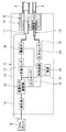
- the insufflation apparatus 1 includes an insufflator 2 which is a main body of the apparatus, a first tube 3 and a second tube 4 communicating with the abdominal cavity 91 of a patient 90, and an insufflator connector (hereinafter referred to as an insufflator). , Simply referred to as a connector.) 5 and a carbon dioxide gas cylinder (hereinafter simply referred to as a gas cylinder) 6 that stores carbon dioxide as an insufflation gas.
- the insufflator 2 is provided with an operation unit (not shown) for performing various operations and settings, and a display unit (not shown) for displaying the pressure in the abdominal cavity 91, the air flow rate, and the like.
- the connector 5 is used to connect one end of each of the first and second tubes 3 and 4 to the insufflator 2.
- the other end of each of the first and second tubes 3 and 4 is connected to a trocar 83 punctured by the patient 90, for example.
- the trocar 83 has a conduit that allows the first and second tubes 3 and 4 and the abdominal cavity 91 to communicate with each other.
- the connector 5 may be a disposable type connector.
- the insufflator 2 includes a first base part 11, a second base part 12, and a receptacle 10 provided with the first and second base parts 11 and 12.
- the receptacle 10 is fitted with a connector main body of the connector 5 described later.
- the connector 5 is used to connect the first and second tubes 3 and 4 to the first and second base parts 11 and 12.
- the first tube 3 is connected to the first base part 11 via the connector 5.
- the second tube 4 is connected to the second base part 12 via the connector 5.
- the first tube 3 is for supplying the gas for insufflation to the abdominal cavity 91 (see FIG. 1) of the patient 90.
- the second tube 4 is for transmitting the pressure in the abdominal cavity 91 of the patient 90.
- die parts 11 and 12 is demonstrated in detail later.
- the insufflator 2 further has an air supply line 13.
- One end of the air supply line 13 is connected to the first base part 11.
- the other end of the air supply line 13 is connected to the gas cylinder 6.
- the air supply line 13 is a line that guides the gas for gas and gas from the gas cylinder 6 (carbon dioxide) to the first base part 11.
- the insufflator 2 further includes a decompressor 14, a flow rate pressure regulator 15, a pressure sensor 16, a flow rate sensor 17, and an electromagnetic valve 18 provided in this order from the gas cylinder 6 side in the middle of the air supply conduit 13. .
- the decompressor 14 reduces the pressure of the gas for insufflation fed from the gas cylinder 6.
- the flow rate pressure regulator 15 adjusts the flow rate and pressure of the decompressed pneumoperitone gas.
- the pressure sensor 16 measures the pressure of the gas for insufflation adjusted by the flow pressure regulator 15.
- the flow rate sensor 17 measures the flow rate of the gas for insufflation adjusted by the flow rate pressure regulator 15.
- the electromagnetic valve 18 opens and closes the air supply line 13.
- the insufflator 2 further includes a pressure sensor 20 and a pressure measurement line 19 communicating with the pressure sensor 20.
- One end of the pressure measurement pipe line 19 is connected to the second base part 12.
- the other end of the pressure measurement pipe line 19 is connected to the pressure sensor 20.
- the pressure measurement line 19 is a line that transmits the pressure in the abdominal cavity 91 of the patient 90 transmitted to the second mouthpiece 12 through the second tube 4 to the pressure sensor 20.
- the pressure sensor 20 measures the pressure in the abdominal cavity 91 of the patient 90 transmitted by the pressure measurement line 19.
- the insufflator 2 further includes a control board 21 and a power source 22.
- the control board 21 is electrically connected to the flow rate pressure regulator 15, the pressure sensor 16, the flow rate sensor 17, the electromagnetic valve 18, and the pressure sensor 20 via a signal line.
- the power source 22 is electrically connected to the flow rate pressure regulator 15, the pressure sensor 16, the flow rate sensor 17, the electromagnetic valve 18, the pressure sensor 20, and the control board 21 through a power line.
- the control board 21 is a central processing unit (not shown) that controls the flow rate pressure regulator 15 and the electromagnetic valve 18 based on the operation content and set value input to an operation unit (not shown) and the measurement value of the pressure sensor 20 (hereinafter referred to as a control unit). , Written as CPU).
- the CPU controls the flow rate pressure regulator 15 and the electromagnetic valve 18 so that the pressure in the abdominal cavity 91 of the patient 90 matches the set value, and controls the start and stop of the supply of the gas for abdominal cavity. To do.
- the CPU can also control the flow rate and pressure of the gas for insufflation based on the measurement value of the pressure sensor 16 and the measurement value of the flow sensor 17.
- the control board 21 may further include a storage unit that stores operation contents and setting values input to an operation unit (not shown).
- the CPU may control the flow rate pressure regulator 15 and the electromagnetic valve 18 based on the contents stored in the storage unit.
- FIG. 3 is a cross-sectional view of the connector 5.
- FIG. 4 is a front view of the connector 5 shown in FIG.
- the connector 5 includes a connector main body 50 that fits into the receptacle 10 (see FIG. 2).
- a state in which the connector main body 50 is fitted to the receptacle 10 is referred to as a fitted state.
- the connector main body 50 may be configured by a metal material, may be configured by a resin material, or may be configured by combining a metal material and a resin material.
- FIG. 3 shows an example in which the connector main body 50 is made of a metal material.
- the connector main body 50 connects the first end 50a and the second end 50b, which are located opposite to each other, and the first end 50a and the second end 50b. And an outer peripheral surface 50c.
- FIG. 4 shows the connector 5 as viewed from the second end 50b side.
- a reference direction D is defined as shown in FIG.
- the reference direction D is a direction parallel to an imaginary straight line L1 that intersects the first and second end portions 50a and 50b.
- the shape of the cross section of the connector body 50 perpendicular to the reference direction D is substantially D-shaped.
- the outer peripheral surface 50c of the connector main body 50 includes a curved surface portion 50c1 and a flat surface portion 50c2.
- the shape of the cross section of the connector main body 50 is not limited to the D shape, and may be a circular shape, an elliptical shape, a polygonal shape, or the like, or may be varied according to the position in the reference direction D.
- the connector main body 50 further has a support groove 50d formed in the direction around the axis of the connector main body 50 on the outer peripheral surface 50c.
- a locking member of the receptacle 10 to be described later is fitted into the support groove 50d.
- the direction around the axis of the connector main body 50 means the direction around the central axis of the connector main body 50.
- the central axis of the connector body 50 is parallel to the virtual straight line L1 and the reference direction D.
- the connector 5 is further disposed on the first end portion 50 a side of the connector main body 50 and the second connection portion 52 disposed on the first end portion 50 a side, and on the second end portion 50 b side of the connector main body 50.
- the first port 53 and the second port 54 are provided.
- the first port 53 is arranged at a position to which the first base part 11 is connected in the fitted state
- the second port 54 is arranged at a position to which the second base part 12 is connected in the fitted state. Is done.
- the first port 53 and the second port 54 are arranged in a direction perpendicular to the reference direction D (up and down direction in FIGS. 3 and 4).
- the first and second connection portions 51 and 52 protrude from the first end portion 50a, respectively.
- the first tube 3 is inserted and connected to the first connection portion 51.
- the second tube 4 is inserted and connected to the second connection portion 52.
- the first port 53 is a groove-shaped portion dug in the second end 50 b of the connector main body 50.
- the first port 53 has a shape extending in the reference direction D.
- the shape of the cross section perpendicular to the reference direction D of the first port 53 is a circular shape.
- the first port 53 includes an inner peripheral surface 53a having a central axis parallel to the reference direction D, and a groove 53b formed in the inner peripheral surface 53a in the direction around the central axis.
- the first port 53 is not limited to the groove-shaped portion as described above, and may be configured by a cylindrical part fixed to the second end portion 50b side.
- the second port 54 includes a groove portion 54 a dug in the second end portion 50 b of the connector main body 50 and a bottom portion of the groove portion 54 a so as to extend in the reference direction D. And a projecting portion 54b projecting from.
- the groove portion 54a has a shape extending in the reference direction D.
- the shape of the cross section perpendicular to the reference direction D of the groove 54a is a circular shape.
- the shape of the protrusion 54b is a cylindrical shape extending in the reference direction D.
- a step for attaching a second seal member to be described later is formed at the tip of the protrusion 54b.
- step difference is not an essential component of the protrusion part 54b, and does not need to be provided.
- the second port 54 is not limited to the above-described configuration, and includes a protruding portion 54b and a cylindrical part fixed on the second end 50b side in which the protruding portion 54b is disposed. May be.
- the connector 5 further includes a first pipe 55 for communicating the first port 53 and the first tube 3 connected to the first connection portion 51, a second port 54, and a second connection portion. And a second conduit 56 for communicating with the second tube 4 connected to 52.
- One end of the first conduit 55 opens at the bottom of the first port 53, and the other end opens at the tip of the first connection portion 51.
- the first port 53 communicates with the first tube 3.
- the second pipe 56 has one end opened at the tip of the projecting portion 54 b of the second port 54 and the other end opened at the tip of the second connection portion 52.
- the second port 54 communicates with the second tube 4.
- the connector 5 further includes a first seal member 57 that seals between the first port 53 and the first base 11 in the fitted state, and a second port 54 and a second seal in the fitted state. And a second seal member 58 that seals between the base portion 12.
- the first seal member 57 is disposed in the first port 53. Specifically, the first seal member 57 has an annular shape, and a part thereof is accommodated in the groove 53 b of the first port 53. The remaining portion of the first seal member 57 is exposed in a space surrounded by the inner peripheral surface 53 a of the first port 53.
- the first seal member 57 is made of an elastically deformable material. As the elastically deformable material, for example, a resin material such as rubber is used. Particularly in the present embodiment, the first seal member 57 is an O-ring.
- the second seal member 58 is disposed in the second port 54. Specifically, the second seal member 58 is provided at the tip of the protruding portion 54b of the second port 54 and is used as a gasket.
- the second seal member 58 is made of an elastically deformable material.
- the elastically deformable material for example, a resin material such as rubber is used.
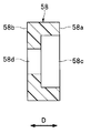
- FIG. 5 is a cross-sectional view of the second seal member 58.
- the external shape of the second seal member 58 is a cylindrical shape extending in the reference direction D.
- the second seal member 58 is continuous with the first surface 58a and the second surface 58b facing opposite to each other, the fitting hole 58c opened in the first surface 58a, and the fitting hole 58c.
- the second surface 58b has a vent hole 58d.
- the second seal member 58 is attached to the protruding portion 54b by fitting the fitting hole 58c into a step (see FIG. 3) formed at the tip of the protruding portion 54b.
- the vent hole 58d communicates with the second conduit 56 (see FIG. 3) when the second seal member 58 is attached to the protruding portion 54b.
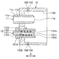
- FIG. 6 is a cross-sectional view of the receptacle 10 and the first and second cap parts 11 and 12.
- FIG. 7 is a front view of the receptacle 10 and the first and second cap parts 11 and 12 shown in FIG.
- the definition of the reference direction D shown in FIG. 6 is the same as the definition of the reference direction D shown in FIG.
- the receptacle 10 is arranged such that the first base part 11 and the second base part 12 are aligned in a direction perpendicular to the reference direction D (up and down direction in FIGS. 6 and 7). Is provided.
- the arrangement of the first base part 11 and the second base part 12 is not limited to the examples shown in FIGS. 6 and 7.
- the first base portion 11 and the second base portion 12 may be arranged in the left-right direction in FIG. 7 or in directions inclined with respect to the up-down direction and the left-right direction in FIG. Also good.
- the receptacle 10, the first base part 11 and the second base part 12 may each be made of a metal material, may be made of a resin material, or a combination of a metal material and a resin material. It may be configured.
- FIG. 6 shows an example in which the receptacle 10, the first base part 11, and the second base part 12 are all made of a metal material.
- the receptacle 10 has a fitting hole 10A into which the connector main body 50 is inserted.
- the fitting hole 10 ⁇ / b> A has a shape corresponding to the connector main body 50.
- the shape of the cross section of the fitting hole 10A perpendicular to the reference direction D is substantially D-shaped.
- the inner peripheral surface of the fitting hole 10A includes a curved surface portion 10A1 and a flat surface portion 10A2.
- the receptacle 10 further has at least one locking member for locking the connector main body 50 and at least one locking member hole.
- the four locking members 10 ⁇ / b> B are arranged at predetermined intervals in the direction around the axis of the receptacle 10.
- the locking member 10B is inserted and fixed in the locking member hole 10C so that the tip portion protrudes into the fitting hole 10A.
- a ball plunger is used as the locking member 10B.
- the direction around the axis of the receptacle 10 means the direction around the central axis of the receptacle 10.
- the central axis of the receptacle 10 is parallel to the reference direction D.
- At least a part of the first base part 11 has a cylindrical shape extending in the reference direction D.
- the entire first base part 11 has the cylindrical shape.
- the first base portion 11 opens at each of the first end portion 11a and the second end portion 11b, the outer peripheral surface 11c, and the first and second end portions 11a and 11b that are located on the opposite sides. 11d.
- the first base part 11 is fixed to the receptacle 10 so that at least a part of the first end part 11a and the outer peripheral surface 11c is located in the fitting hole 10A.
- the pipe line 11d communicates with the fitting hole 10A and the air supply pipe line 13 (see FIG. 2).
- the second base part 12 includes a base body 121 provided so as to be movable in the reference direction D, a biasing member 122 that applies a biasing force to the base body 121 in the reference direction D, a base body 121, and a biasing member.
- a housing member 123 for housing 122 and a retaining member 124 are included.
- the biasing member 122 is a spring, more specifically, a coil spring.
- the base body 121 includes a flange portion 121a, a tubular portion 121b extending from the flange portion 121a in the reference direction D, and a pipe line 121c penetrating the base body 121 in the reference direction D.
- the cross-sectional shape perpendicular to the reference direction D of each of the flange portion 121a and the tubular portion 121b is a circular shape.
- the outer diameter of the flange part 121a is larger than the outer diameter of the tubular part 121b.
- the pipe line 121c opens at each end of the flange part 121a and the tubular part 121b, and communicates with the fitting hole 10A and the pressure measurement pipe line 19 (see FIG. 2).
- the housing member 123 has a cylindrical shape extending in the reference direction D, and is fixed to the receptacle 10 so that a part thereof is positioned in the fitting hole 10A.
- the housing member 123 has a housing hole 123 a that communicates with the fitting hole 10 ⁇ / b> A, and a passage hole 123 b that communicates with the housing hole 123 a and the outside of the receptacle 10.
- the base body 121 is inserted through the accommodation hole 123a and the passage hole 123b.
- the inner diameter of the accommodation hole 123a is slightly larger than the outer diameter of the flange portion 121a. Thereby, the base body 121 is movable in the reference direction D in the accommodation hole 123a.
- the inner diameter of the passage hole 123b is slightly larger than the outer diameter of the tubular part 121b, but smaller than the outer diameter of the flange part 121a. Therefore, the tubular portion 121b can pass through the passage hole 123b, but the flange portion 121a cannot pass through the passage hole 123b. A step due to the difference in inner diameter exists between the accommodation hole 123a and the passage hole 123b.
- the urging member 122 (coil spring) is housed in the housing hole 123 a of the housing member 123, and between the flange portion 121 a of the base body 121 and the step of the housing member 123. It is sandwiched.
- the tubular portion 121b of the base body 121 is inserted inside the urging member 122 (coil spring).
- the retaining member 124 is fixed to the tubular portion 121b of the base body 121 outside the receptacle 10.
- the retaining member 124 has a function of preventing the base body 121 from falling off the housing member 123.
- FIG. 8 is a cross-sectional view showing a fitted state.
- FIG. 9 is a cross-sectional view of the first port 53, the first seal member 57, and the first base portion 11 in the fitted state.
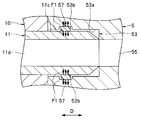
- FIG. 10 is a cross-sectional view of the second port 54, the second seal member 58, and the second base portion 12 in the fitted state.
- the flat surface portion 50 c 2 (see FIG. 4) of the outer peripheral surface 50 c of the connector main body 50 is formed on the inner peripheral surface of the fitting hole 10 A of the receptacle 10. It is inserted into the fitting hole 10A in a posture that matches the flat surface portion 10A2 (see FIG. 7). Then, as shown in FIG. 8, the connector main body 50 is inserted into the support groove 50 d of the connector main body 50 to a position where the distal end portion of the locking member 10 ⁇ / b> B is fitted. As a result, the connector body 50 is fitted into the receptacle 10.
- the planar portions 10A2 and 50c2 have a function of determining the posture of the connector main body 50 with respect to the receptacle 10.
- the locking member 10 ⁇ / b> B has a function of locking the connector main body 50 and preventing the connector main body 50 from dropping from the receptacle 10.
- the flat portions 10A2 and 50c2, the locking member 10B, and the support groove 50d are not essential components of the receptacle 10 and the connector main body 50, and may not be provided.
- the first port 53 is connected to and communicates with the first base unit 11 as follows. As shown in FIG. 8 and FIG. 9, in the fitted state, the first port 53 and the first base part 11 are at least part of the first port 53 extending in the reference direction D and the reference direction D. Are connected so as to overlap at least a part of the first base part 11 extending in the direction. In the present embodiment, the outer diameter of the first base portion 11 is smaller than the inner diameter of the first port 53 so that the first base portion 11 is inserted into the first port 53. Further, in the present embodiment, almost the entire first port 53 and a portion of the first base portion 11 located in the fitting hole 10A overlap in the reference direction D.
- first port 53 and the first base part 11 communicate with each other by connecting the first port 53 to the first base part 11.
- the opening of the first pipe 55 of the connector 5 and the opening of the pipe 11d of the first base 11 are configured so that their positions substantially coincide with each other in the fitted state.
- the first path 53 is configured by connecting and communicating with the first port 53 and the first base part 11.
- the first route is a route for supplying the gas for insufflation into the abdominal cavity 91 (see FIG. 1) of the patient 90.
- the air supply pipe line 13 shown in FIG. 2 constitutes a part of the first path and supplies the gas for insufflation.
- the first tube 3 constitutes another part of the first path.
- the second port 54 is connected and communicated with the second base part 12 as follows. As shown in FIGS. 8 and 10, the second port 54 is different from the second base part 12 in at least a part of the second port 54 and at least the second base part 12 in the reference direction D. A part is connected so as to be pressed against each other.
- the housing member 123 of the second base portion 12 is inserted into the groove portion 54 a of the second port 54, and the housing member 123
- the outer diameter of the accommodating member 123 is smaller than the inner diameter of the groove portion 54a so that the protruding portion 54b of the second port 54 is inserted into the accommodating hole 123a, and the outer diameter of the protruding portion 54b is the inner diameter of the accommodating hole 123a. Smaller than.
- the second seal member 58 is also inserted into the accommodation hole 123 a of the accommodation member 123. Therefore, the outer diameter of the second seal member 58 is smaller than the inner diameter of the accommodation hole 123a.
- the protrusion 54b inserted into the accommodation hole 123a pushes the base body 121 of the second base part 12 into.
- a biasing force is applied to the base body 121 in a direction opposite to the pushed direction by the restoring force of the biasing member 122.
- the protruding portion 54b receives a repulsive force in the direction opposite to the direction in which the protruding portion 54b is pushed. In this way, the protruding portion 54b and the base body 121 are connected so as to push each other.
- the second port 54 and the second base part 12 communicate with each other by connecting the second port 54 to the second base part 12.
- the opening of the second pipe 56 of the connector 5 and the opening of the pipe 121c of the base body 121 are substantially coincided with the position of the opening of the vent hole 58d of the second seal member 58 in the fitted state. Is configured to do.
- the second path is configured by connecting and communicating between the second port 54 and the second base part 12.
- the second path is a path for transmitting pressure in the abdominal cavity 91 (see FIG. 1) of the patient 90.
- the pressure measurement pipe line 19 shown in FIG. 2 constitutes a part of the second path.
- the second tube 4 constitutes another part of the second path.
- the first seal member 57 is a member that seals between the first port 53 and the first base portion 11 in the fitted state.
- the inner peripheral surface 53 a of the first port 53 faces a part of the outer peripheral surface 11 c of the first base part 11.
- the first seal member 57 is between the at least part of the overlapping first port 53 and at least part of the first base part 11, specifically, the inner peripheral surface 53 a and the outer peripheral surface 11 c.
- a part of the outer peripheral surface 11 c described above can be said to be a part of the outer peripheral surface of the first base portion 11 that overlaps the first port 53.
- the inner diameter of the first seal member 57 is slightly smaller than the outer diameter of the first base part 11.
- the first seal member 57 is deformed by receiving an external force from each of the overlapped first port 53 and first base part 11.
- a first repulsive force F1 is generated from the first seal member 57 toward each of the first port 53 and the first base part 11.
- the first seal member 57 is in close contact with the first port 53 and the first base part 11, and the space between the first port 53 and the first base part 11 is sealed.
- the second seal member 58 is a member that seals between the second port 54 and the second base portion 12 in the fitted state. In the fitted state, the second seal member 58 is located in the second port 54 so as to be positioned between the projecting portion 54 b of the second port 54 that presses against the base body 121 of the second base portion 12. Is arranged.
- the second seal member 58 is deformed by receiving an external force from each of the projecting portion 54b and the base body 121 that are pressed against each other.
- a second repulsive force F ⁇ b> 2 is generated from the second seal member 58 toward each of the second port 54 and the second base portion 12. Due to the second repulsive force F2, the second seal member 58 comes into close contact with the protruding portion 54b and the base body 121, and the space between the second port 54 and the second base portion 12 is sealed.
- the amount of compression of the second seal member 58 depends on the magnitude of the external force that the second seal member 58 receives from both the protrusion 54b and the base body 121.
- the magnitude of this external force depends on the urging force applied to the base body 121 by the urging member 122.
- the magnitude of the urging force can be adjusted by the length of the protruding portion 54b in the reference direction D, that is, the distance by which the protruding portion 54b pushes the base body 121, the characteristic value of the urging member 122, specifically the spring constant. .
- the degree of adhesion of the second seal member 58 to the protrusion 54b and the base body 121 (hereinafter referred to as the degree of adhesion of the second seal member 58). Can be adjusted.
- the first tube 3 is connected to the first base part 11 via the first pipe 55 of the connector 5 and the pipe 11d of the first base part 11. 13 (see FIG. 2)
- the second tube 4 is connected to the second base part 12 via the second pipe 56 of the connector 5 and the pipe 121c of the base body 121. It communicates with the measurement pipeline 19 (see FIG. 2).
- the connector 5 is connected to the first and second cap parts 11 and 12 so that the first and second tubes 3 and 4 communicate with the air supply line 13 and the pressure measurement line 19, respectively. This is used to connect the two tubes 3 and 4.
- the receptacle 10 is provided with first and second cap parts 11 and 12.
- the connector main body 50 of the connector 5 is provided with first and second ports 53 and 54, and the first and second tubes 3 and 4 are connected thereto.
- the first and second ports 53 and 54 communicate with the first and second tubes 3 and 4.
- the first port 53 is connected and communicated with the first base part 11, and the second port 54 is connected and communicated with the second base part 12.
- the first and second tubes 3 and 4 are connected to the first and second base portions 11 and 12 through the connector 5 with a single touch. be able to.
- the insufflator of the comparative example has first and second base parts, and a receptacle provided with the first and second base parts.
- die part is the same as the structure of the 1st nozzle
- Other configurations of the insufflator of the comparative example are the same as those of the insufflator 2 in the present embodiment.
- the connector of the comparative example includes a connector main body that fits into the receptacle of the insufflator of the comparative example, first and second ports provided in the connector main body, and first and second sealing members. It has.
- the configuration of each of the first and second ports is the same as the configuration of the first port 53 in the present embodiment.
- the configuration and arrangement of each of the first and second seal members are the same as the configuration and arrangement of the first seal member 57 in the present embodiment.
- Each of the first and second seal members is specifically an O-ring.
- Other configurations of the connector of the comparative example are the same as those of the connector 5 according to the present embodiment.
- the first seal member is in close contact with the first port and the first base part, thereby sealing between the first port and the first base part.
- the second seal member is in close contact with the second port and the second base part, thereby sealing between the second port and the second base part.
- the connector is arranged so that the central axis of the first port coincides with the central axis of the first base part. Even if the main body is fitted to the receptacle, the center axis of the second port and the center axis of the second base part may be displaced. When the shift amount of the central axis increases, the second seal member cannot be securely adhered to the second port and the second base part, and the second base part is sealed in an incomplete state. End up.
- the central axis of the first port 53 and the central axis of the first base part 11 are Even if the connector main body 50 is fitted to the receptacle 10 so as to match, the center axis of the second port 54 and the center axis of the second base portion 12 may be displaced.
- the second port 54 is different from the second base part 12 in the reference direction D with the protruding part 54b of the second port 54 and the base body 121 of the second base part 12.
- the second seal member 58 is positioned between the projecting portion 54 b and the base body 121 that are pressed against each other. Therefore, according to the present embodiment, the second port member 54 and the second port 54 are deformed by deforming the second seal member 58 regardless of whether or not the center axis of the projecting portion 54b and the center axis of the base body 121 are displaced. It is possible to seal the space between the base portion 12 and the base portion 12.
- the second base part 12 is sealed in an incomplete state while preventing the first base part 11 from being sealed in an incomplete state. This can be prevented.
- the second base portion 12 is provided with a biasing member 122. If the urging member 122 is not provided and the base body 121 is fixed to the housing member 123, the position of the flange portion 121a of the base body 121 in the reference direction D varies, The second seal member 58 may not be sufficiently deformed due to variations in the length of the protruding portion 54b of the second port 54 and variations in the length of the second seal member 58 in the reference direction D.
- the second seal member 58 can be reliably deformed by providing the urging member 122 and configuring the base body 121 to be pushed by the protruding portion 54b. Thereby, according to this Embodiment, it can prevent more effectively that the 2nd nozzle
- the second seal member 58 compresses in the reference direction D and expands in the radial direction of the second seal member 58 when receiving an external force from each of the protruding portion 54 b and the base body 121. (See FIG. 10).
- the second seal member 58 expands in the radial direction, the second seal member 58 comes into close contact with the inner peripheral surface of the accommodation hole 123 a of the accommodation member 123, and the second port 54 and the second base portion 12 are in contact with each other.
- the gap is sealed. Thereby, according to this Embodiment, it can prevent more effectively that the 2nd nozzle
- the first and second tubes 3, 4 can be connected to the first and second base parts 11, 12 with one touch, and the first and second tubes It is possible to prevent the second base parts 11 and 12 from being sealed in an incomplete state.
- the first and second sealing members O The inner diameter of each of the rings
- the first seal member is securely attached to the first port and the first base part
- the second seal member is connected to the second port and the second base part. It is conceivable to ensure close contact.
- a force hereinafter referred to as a fitting force
- a booster mechanism such as a lever mechanism that can obtain a boosting effect needs to be provided in the insufflator.
- the insufflator is expensive for the boost mechanism.
- the first and second base portions 11 and 12 can be prevented from being sealed in an incomplete state. It is not necessary to make the inner diameter of the seal member 57 (O-ring) smaller than necessary. Thereby, according to this Embodiment, compared with a comparative example, a fitting force can be made small. In the present embodiment, the booster mechanism as described above is not necessary. From these things, according to this Embodiment, compared with a comparative example, while being able to improve the convenience for a user, the price of the insufflator 2 can be reduced.
- the connector body 50 is provided with a flat surface portion 50c2, and the fitting hole 10A of the receptacle 10 into which the connector main body 50 is inserted is provided with a flat surface portion 10A2.
- the posture of the connector main body 50 with respect to the receptacle 10 can be easily determined by matching the flat portions 10A2 and 50c2.
- the second path is a path for transmitting the pressure in the abdominal cavity 91 of the patient 90 and is used for supplying the gas for insufflation to the abdominal cavity 91 of the patient 90.
- the internal pressure is smaller than that of the first path which is the path. Therefore, according to the present embodiment, the degree of adhesion of the second seal member 58 is higher than that in the case where the second path is a path for supplying the gas for insufflation to the abdominal cavity 91 of the patient 90. It can be made small and the fitting force can be made small.
- the central axis of the second pipe 56 and the central axis of the pipe 121c should coincide with each other in order to ensure communication between the second pipe 56 and the pipe 121c of the base body 121. Is desirable. However, in practice, the central axis of the second pipe 56 and the central axis of the pipe 121c may be shifted. On the other hand, in the present embodiment, as shown in FIG. 10, the inner diameter of the second pipeline 56 is slightly larger than the inner diameter of the pipeline 121c.
- the 2nd pipe line 56 and the pipe line 121c are connected reliably.
- the internal diameter of the 2nd pipe line 56 may be the same as the internal diameter of the pipe line 121c, and may be larger than the example shown in FIG.
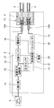
- FIG. 11 is an explanatory diagram showing a configuration of a modified example of the pneumoperitoneum apparatus 1.
- FIG. 12 is a cross-sectional view of a modified example of the connector 5.
- FIG. 13 is a cross-sectional view of the receptacle 10 and a modified example of the first and second cap portions.
- the insufflator 2 of the insufflation apparatus 1 has the first base part 12 ⁇ / b> A and the second base part 12 instead of the first base part 11 and the second base part 12. It has a base 12B.
- the other configuration of the insufflator 2 in the modification is the same as that of the insufflator 2 shown in FIG.
- the first and second cap parts 12 ⁇ / b> A and 12 ⁇ / b> B are provided in the receptacle 10.
- An air supply conduit 13 is connected to the first base portion 12A.
- a pressure measurement pipe line 19 is connected to the second base part 12B.
- the connector 5 includes the first port 53, the second port 54, the first seal member 57, and the second seal member 58 instead of the first port 53, the second port 54, the first seal member 57, and the second seal member 58.
- a port 54A, a second port 54B, a first seal member 58A, and a second seal member 58B are provided.
- the first port 54A is arranged at a position where the first base part 12A is connected in the fitted state
- the second port 54B is arranged at a position where the second base part 12B is connected in the fitted state. Is done.
- each of the first and second ports 54A and 54B is the same as the configuration of the second port 54. That is, as shown in FIG. 12, the first port 54 ⁇ / b> A has a groove 54 ⁇ / b> Aa dug in the second end 50 b of the connector main body 50 and a protrusion that protrudes from the bottom of the groove 54 ⁇ / b> Aa so as to extend in the reference direction D. Part 54Ab.
- the shapes of the groove 54Aa and the protrusion 54Ab are the same as the shapes of the groove 54a and the protrusion 54b shown in FIGS.
- a step for attaching the first seal member 58A is formed at the tip of the protrusion 54Ab.
- the second port 54B includes a groove 54Ba dug in the second end 50b of the connector body 50 and a protrusion protruding from the bottom of the groove 54Ba so as to extend in the reference direction D. Part 54Bb.
- the shape of the groove 54Ba and the protrusion 54Bb is the same as the shape of the groove 54a and the protrusion 54b shown in FIGS.
- a step for attaching the second seal member 58B is formed at the tip of the protrusion 54Bb.
- the length of the protrusion 54Ab in the reference direction D is larger than the length of the protrusion 54Bb in the reference direction D.
- one end of the first pipe 55 is opened at the tip of the protruding portion 54Ab of the first port 54A, and the other end is opened at the tip of the first connecting portion 51.
- the first port 54 ⁇ / b> A communicates with the first tube 3.
- one end of the second duct 56 opens at the tip of the projecting portion 54Bb of the second port 54B, and the other end opens at the tip of the second connection portion 52.
- the second port 54 ⁇ / b> B communicates with the second tube 4.
- the first port 54A is connected and communicated with the first base part 12A
- the second port 54B is connected and communicated with the second base part 12B.
- the first seal member 58A seals between the first port 54A and the first base portion 12A in the fitted state.
- the second seal member 58B seals between the second port 54B and the second base part 12B in the fitted state.
- the first seal member 58A is provided at the tip of the protrusion 54Ab of the first port 54A.
- the second seal member 58B is provided at the tip of the protrusion 54Bb of the second port 54B.
- the material of each of the first and second seal members 58A and 58B is the same as the material of the second seal member 58.
- each of the first and second seal members 58A and 58B is the same as the shape of the second seal member 58 shown in FIG. That is, the first and second seal members 58A and 58B are respectively provided with a first surface 58a and a second surface 58b facing opposite to each other, and a fitting hole 58c opened in the first surface 58a. It has a vent hole 58d that is continuous with the fitting hole 58c and opens on the second surface 58b.
- the arrangement of the first and second base parts 12A, 12B in the receptacle 10 is the same as the arrangement of the first and second base parts 11, 12.
- the material of each of the first and second base parts 12 ⁇ / b> A and 12 ⁇ / b> B is the same as the material of the second base part 12.
- each of the first and second base parts 12A and 12B is the same as that of the second base part 12. That is, as shown in FIG. 13, the first base portion 12A includes a base body 121A that is movably provided in the reference direction D, and a biasing member that applies a biasing force in the reference direction D to the base body 121A. 122A, a housing member 123A for housing the base body 121A and the urging member 122A, and a retaining member 124A. As shown in FIG. 13, the urging member 122A is a spring, more specifically, a coil spring.
- the second base portion 12B includes a base body 121B provided to be movable in the reference direction D, and a biasing member that applies a biasing force in the reference direction D to the base body 121B.
- 122B a base member 121B that houses the base body 121B and the biasing member 122B, and a retaining member 124B.
- the urging member 122B is a spring, more specifically a coil spring.
- Each configuration of the base body 121A, 121B is the same as that of the base body 121 shown in FIG. That is, the base bodies 121A and 121B each include a flange portion 121a, a tubular portion 121b, and a conduit 121c.
- the pipe 121c of the base body 121A communicates with the fitting hole 10A of the receptacle 10 and the air supply pipe 13 (see FIG. 11).
- the pipe 121c of the base body 121B communicates with the fitting hole 10A and the pressure measurement pipe 19 (see FIG. 11).
- each of the accommodation members 123A and 123B is the same as the configuration of the accommodation member 123 shown in FIG. That is, each of the housing members 123A and 123B has a cylindrical shape extending in the reference direction D, and is fixed to the receptacle 10 so that a part thereof is located in the fitting hole 10A.
- the housing members 123A and 123B each have a housing hole 123a and a passage hole 123b. A step due to the difference in inner diameter exists between the accommodation hole 123a and the passage hole 123b.
- the base body 121A is inserted through the accommodation hole 123a and the passage hole 123b of the accommodation member 123A.
- the base body 121A is movable in the reference direction D within the housing hole 123a of the housing member 123A.
- the urging member 122A (coil spring) is housed in the housing hole 123a of the housing member 123A, and is sandwiched between the flange portion 121a of the base body 121A and the step of the housing member 123A.
- the tubular portion 121b of the base body 121A is inserted inside the urging member 122A (coil spring).
- the base body 121B is inserted through the accommodation hole 123a and the passage hole 123b of the accommodation member 123B.
- the base body 121B is movable in the reference direction D within the accommodation hole 123a of the accommodation member 123B.
- the urging member 122B (coil spring) is housed in the housing hole 123a of the housing member 123B, and is sandwiched between the flange portion 121a of the base body 121B and the step of the housing member 123B.
- the tubular portion 121b of the base body 121B is inserted inside the urging member 122B (coil spring).
- the retaining member 124A is fixed to the tubular portion 121b of the base body 121A outside the receptacle 10.
- the retaining member 124A has a function of preventing the base body 121A from falling off the housing member 123A.
- the retaining member 124B is fixed to the tubular portion 121b of the base body 121B outside the receptacle 10.
- the retaining member 124B has a function of preventing the base body 121B from falling off the housing member 123B.
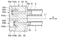
- FIG. 14 is a cross-sectional view showing a fitting state in the modified example.
- the first port 54A is connected to and communicates with the first base portion 12A.
- the connection method between the first port 54A and the first base part 12A is the same as the connection method between the second port 54 and the second base part 12 described with reference to FIGS.
- the second port 54, the groove 54a, the protrusion 54b, the second base part 12, the base body 121, the urging member 122, and the housing are included in the description of the method for connecting the second port 54 and the second base part 12.
- the member 123 and the second seal member 58 are respectively connected to the first port 54A, the groove 54Aa, the protruding portion 54Ab, the first base portion 12A, the base body 121A, the biasing member 122A, the housing member 123A, and the first seal member. If replaced with 58A, the connection method between the first port 54A and the first base portion 12A will be described.
- the second port 54B is connected to and communicates with the second base portion 12B.
- the connection method between the second port 54B and the second base part 12B is the same as the connection method between the second port 54 and the second base part 12 described with reference to FIGS.
- the second port 54, the groove 54a, the protrusion 54b, the second base part 12, the base body 121, the urging member 122, and the housing are included in the description of the method for connecting the second port 54 and the second base part 12.
- the member 123 and the second seal member 58 are respectively connected to the second port 54B, the groove portion 54Ba, the protruding portion 54Bb, the second base portion 12B, the base body 121B, the biasing member 122B, the housing member 123B, and the second seal member. If replaced with 58B, the connection method between the second port 54B and the second base 12B will be described.
- the protrusion 54Ab of the first port 54A inserted into the accommodation hole 123a of the accommodation member 123A of the first base part 12A pushes the base body 121A of the first base part 12A
- the second The protrusion 54Bb of the second port 54B inserted into the accommodation hole 123a of the accommodation member 123B of the base part 12B pushes the base body 121B of the second base part 12B.
- the length of the protrusion 54Ab in the reference direction D is larger than the length of the protrusion 54Bb in the reference direction D. Therefore, as shown in FIG.
- the distance that the protrusion 54Ab pushes the base body 121A is larger than the distance that the protrusion 54Bb pushes the base body 121B.
- the compression amount of the urging member 122A in the reference direction D is larger than the compression amount of the urging member 122B in the reference direction D, and the urging force applied to the base body 121A by the urging member 122A is the urging member. It becomes larger than the urging force given to the base body 121B by 122B.
- the first seal member 58A is a member that seals between the first port 54A and the first base portion 12A in the fitted state.
- the method for sealing the first seal member 58A between the first port 54A and the first base portion 12A is the second seal member 58 described with reference to FIGS. This is the same as the method of sealing between the port 54 and the second base 12.
- the second port 54, the protruding portion 54b, the second base portion 12, and the base in the description of the method in which the second seal member 58 seals between the second port 54 and the second base portion 12.
- the main body 121, the biasing member 122, and the second seal member 58 are respectively connected to the first port 54A, the protruding portion 54Ab, the first base portion 12A, the base body 121A, the biasing member 122A, and the first seal member 58A. If replaced, the first sealing member 58A will explain the method of sealing between the first port 54A and the first base portion 12A.
- the second seal member 58B is a member that seals between the second port 54B and the second base part 12B in the fitted state.
- the second seal member 58B seals between the second port 54B and the second base part 12B.
- the second seal member 58 described with reference to FIGS. 8 and 10 is the second seal member 58B. This is the same as the method of sealing between the port 54 and the second base 12.
- the second port 54, the protruding portion 54b, the second base portion 12, and the base in the description of the method in which the second seal member 58 seals between the second port 54 and the second base portion 12.
- the main body 121, the urging member 122, and the second seal member 58 are respectively connected to the second port 54B, the protruding portion 54Bb, the second base portion 12B, the base body 121B, the urging member 122B, and the second seal member 58B. If replaced, the second sealing member 58B will explain the method of sealing between the second port 54B and the second base part 12B.
- the distance by which the protrusion 54Ab pushes the base body 121A is larger than the distance by which the protrusion 54Bb pushes the base body 121B, and is given to the base body 121A by the biasing member 122A.
- the urging force is larger than the urging force applied to the base body 121B by the urging member 122B. Therefore, the compression amount of the first seal member 58A is larger than the compression amount of the second seal member 58B, and as a result, the degree of adhesion of the first seal member 58A with respect to the protrusion 54Ab and the base body 121A (hereinafter referred to as “the first seal member 58A”).
- the degree of adhesion of the first seal member 58A is the degree of adhesion of the second seal member 58B to the protrusion 54Bb and the base body 121B (hereinafter referred to as the degree of adhesion of the second seal member 58B). Bigger than.
- the first path 54A is connected to and communicates with the first base part 12A, so that the first path is configured, and the second port 54B is connected to and communicates with the second base part 12B.
- a second path is configured.
- the first route is a route for supplying the gas for insufflation to the abdominal cavity 91 (see FIG. 1) of the patient 90.
- the second path is a path for transmitting pressure in the abdominal cavity 91 of the patient 90.
- the internal pressure of the first path is greater than the internal pressure of the second path. If the close contact degree of the first seal member 58A is smaller than the close contact degree of the second seal member 58B, there is a possibility that gas leaks from between the first port 54A and the first base part 12A. is there. In order to prevent this, if the close contact degree of the first seal member 58A is increased, the fitting force is increased.
- the adhesion degree of the first seal member 58A is made larger than the adhesion degree of the second seal member 58B. That is, in the modified example, the first port 54A is obtained by correlating the internal pressure of the path with the close contact degree so that the close contact degree of the seal member increases when the internal pressure of the path in which the seal member is used is large. The fitting force can be reduced while preventing gas from leaking from between the first base portion 12A and the first base portion 12A.
- the spring constant of the urging member 122A and the spring constant of the urging member 122B may be the same or different from each other. Further, by making the length of the protrusion 54Ab in the reference direction D equal to the length of the protrusion 54Bb in the reference direction D, the spring constant of the biasing member 122A and the spring constant of the biasing member 122B are made different from each other. The compression amount of the first seal member 58A and the compression amount of the second seal member 58B may be different from each other. In this case, it is preferable to adjust the spring constant of the urging member 122A and the spring constant of the urging member 122B so that the compression amount of the first seal member 58A is larger than the compression amount of the second seal member 58B. .
- urging members 122A and 122B are provided in the first and second cap portions 12A and 12B, respectively. If the urging members 122A and 122B are not provided and the base bodies 121A and 121B are fixed to the housing members 123A and 123B, respectively, the flange portions of the base bodies 121A and 121B in the reference direction D are provided. Due to variations in the position of 121a, variations in the lengths of the protrusions 54Ab and 54Bb in the reference direction D, and variations in the lengths of the first and second seal members 58A and 58B in the reference direction D, The first and second seal members 58A and 58B may not be sufficiently deformed.
- the biasing members 122A and 122B are provided, and the base body 121A is pushed in by the protrusion 54Ab, and the base body 121B is pushed in by the protrusion 54Bb.
- the two sealing members 58A and 58B can be reliably deformed. Thereby, it can prevent that 1st and 2nd nozzle
- an O-ring may be used instead of the second seal member 58 shown in FIG. This O-ring is attached to the tip of the protrusion 54b.
- a second path configured by connecting and communicating with the second mouth portion 12 by the second port 54 is an abdominal cavity 91 of the patient 90.
- the first path which is a path for transmitting the internal pressure and is configured by connecting and communicating with the first base portion 11 by the first port 53 is in the abdominal cavity 91 of the patient 90. It may be a path for supplying gas.
- both the first path and the second path may be a supply for feeding the gas for insufflation.
- more pneumoperitoneum gas can be supplied into the abdominal cavity 91 of the patient 90, and the pneumoperitoneum device 1 can be applied to the abdominal cavity 91 having a larger volume.
- the internal pressure of the first path may be the same as the internal pressure of the second path, or may be greater than the internal pressure of the second path. In the latter case, the fitting force can be reduced while preventing gas from leaking from between the first port 53 and the first base part 11.
- two sets of ports, bases and seal members are provided, but three or more sets of ports, bases and seal members may be provided. Thereby, three or more tubes can be connected with one touch.
Landscapes
- Health & Medical Sciences (AREA)
- Heart & Thoracic Surgery (AREA)
- Life Sciences & Earth Sciences (AREA)
- General Health & Medical Sciences (AREA)
- Veterinary Medicine (AREA)
- Biomedical Technology (AREA)
- Public Health (AREA)
- Animal Behavior & Ethology (AREA)
- Engineering & Computer Science (AREA)
- Anesthesiology (AREA)
- Hematology (AREA)
- Pulmonology (AREA)
- Surgery (AREA)
- Nuclear Medicine, Radiotherapy & Molecular Imaging (AREA)
- Medical Informatics (AREA)
- Molecular Biology (AREA)
- Endoscopes (AREA)
- Surgical Instruments (AREA)
Abstract
La présente invention concerne un connecteur 5 qui comporte un premier orifice 53, un second orifice 54, un premier élément d'étanchéité 57 et un second élément d'étanchéité 58. Le premier orifice 54 et un premier embout 11 sont reliés de façon qu'au moins une partie du premier orifice 53 qui s'étend dans une direction de référence D et au moins une partie du premier embout 11 qui s'étend dans la direction de référence D se chevauchent, et que le premier élément d'étanchéité 57 se trouve entre les deux parties qui se chevauchent. Le second orifice 54 et un second embout 12 sont reliés de façon qu'au moins une partie du second orifice 54 et au moins une partie du second embout 12 se poussent l'une contre l'autre dans la direction de référence D, et que le second élément d'étanchéité 58 se trouve entre les deux parties qui se poussent l'une contre l'autre.
Priority Applications (3)
| Application Number | Priority Date | Filing Date | Title |
|---|---|---|---|
| CN201880088774.0A CN111727014B (zh) | 2018-02-06 | 2018-08-09 | 气腹器用连接器和气腹装置 |
| JP2019570280A JP7123080B2 (ja) | 2018-02-06 | 2018-08-09 | 気腹器、気腹器用コネクタおよび気腹装置 |
| US16/932,292 US11890410B2 (en) | 2018-02-06 | 2020-07-17 | Insufflator, connector for insufflator, and insufflation apparatus |
Applications Claiming Priority (2)
| Application Number | Priority Date | Filing Date | Title |
|---|---|---|---|
| JP2018-019317 | 2018-02-06 | ||
| JP2018019317 | 2018-02-06 |
Related Child Applications (1)
| Application Number | Title | Priority Date | Filing Date |
|---|---|---|---|
| US16/932,292 Continuation US11890410B2 (en) | 2018-02-06 | 2020-07-17 | Insufflator, connector for insufflator, and insufflation apparatus |
Publications (1)
| Publication Number | Publication Date |
|---|---|
| WO2019155661A1 true WO2019155661A1 (fr) | 2019-08-15 |
Family
ID=67548103
Family Applications (1)
| Application Number | Title | Priority Date | Filing Date |
|---|---|---|---|
| PCT/JP2018/029963 Ceased WO2019155661A1 (fr) | 2018-02-06 | 2018-08-09 | Connecteur pour appareil de pneumopéritoine et dispositif de pneumopéritoine |
Country Status (4)
| Country | Link |
|---|---|
| US (1) | US11890410B2 (fr) |
| JP (1) | JP7123080B2 (fr) |
| CN (1) | CN111727014B (fr) |
| WO (1) | WO2019155661A1 (fr) |
Cited By (1)
| Publication number | Priority date | Publication date | Assignee | Title |
|---|---|---|---|---|
| JP2024522462A (ja) * | 2021-05-17 | 2024-06-21 | ヴェー.オー.エム. ワールド オブ メディシン ゲーエムベーハー | 医療用ポンプのための連結デバイス |
Families Citing this family (2)
| Publication number | Priority date | Publication date | Assignee | Title |
|---|---|---|---|---|
| CN113577532B (zh) * | 2021-07-29 | 2023-03-21 | 中荷医疗科技(杭州)有限公司 | 一种气腹机机械保护阀 |
| WO2023052952A1 (fr) * | 2021-09-29 | 2023-04-06 | Cilag Gmbh International | Systèmes chirurgicaux pour insuffler indépendamment deux espaces anatomiques séparés |
Citations (2)
| Publication number | Priority date | Publication date | Assignee | Title |
|---|---|---|---|---|
| JP2005110978A (ja) * | 2003-10-08 | 2005-04-28 | Olympus Corp | 送気装置 |
| JP2012511394A (ja) * | 2008-12-10 | 2012-05-24 | ミニマリー インバシブ デバイシーズ, エルエルシー | 手術用顕微鏡使用中に手術野の可視化を最適化し維持するためのシステムおよび方法 |
Family Cites Families (18)
| Publication number | Priority date | Publication date | Assignee | Title |
|---|---|---|---|---|
| US3244425A (en) * | 1961-09-23 | 1966-04-05 | Crane Packing Ltd | Axially biased rotary face seal |
| US5492147A (en) * | 1995-01-17 | 1996-02-20 | Aeroquip Corporation | Dry break coupling |
| JP3715010B2 (ja) * | 1995-11-20 | 2005-11-09 | オリンパス株式会社 | 外套管付き気腹針 |
| JP2005245772A (ja) | 2004-03-04 | 2005-09-15 | Olympus Corp | 気腹システム |
| JP4573555B2 (ja) * | 2004-03-30 | 2010-11-04 | オリンパス株式会社 | 内視鏡外科手術システム |
| US20070163585A1 (en) * | 2006-01-13 | 2007-07-19 | Olympus Medical Systems Corp. | Method for accessing abdominal cavity and medical procedure via natural orifice |
| EP2139377B1 (fr) * | 2007-03-30 | 2017-08-09 | Covidien LP | Ensemble orifice laparoscopique |
| BR112012004514A8 (pt) * | 2009-08-31 | 2016-10-04 | Bracco Diagnostics Inc | adaptador de gás em linha para aparelho endoscópico |
| WO2012044410A2 (fr) * | 2010-09-20 | 2012-04-05 | Surgiquest, Inc. | Système de filtration à flux multiples |
| JP5592826B2 (ja) * | 2011-03-29 | 2014-09-17 | オリンパスメディカルシステムズ株式会社 | 気腹装置 |
| US8356794B1 (en) * | 2011-08-12 | 2013-01-22 | Liu Hsiu-Hsiung | Quick release connector |
| JP6242823B2 (ja) * | 2013-01-28 | 2017-12-06 | テルモ株式会社 | チューブ接続構造 |
| CN105431093B (zh) * | 2013-08-06 | 2019-03-29 | 奥林巴斯株式会社 | 气腹装置 |
| JP5838189B2 (ja) * | 2013-09-06 | 2016-01-06 | 富士フイルム株式会社 | 内視鏡システム |
| US10631713B2 (en) * | 2014-03-17 | 2020-04-28 | Intuitive Surgical Operations, Inc. | Multi-stage instrument connector |
| JP5829367B1 (ja) * | 2014-05-13 | 2015-12-09 | オリンパス株式会社 | 内視鏡接続具 |
| US10159809B2 (en) * | 2015-01-30 | 2018-12-25 | Surgiquest, Inc. | Multipath filter assembly with integrated gaseous seal for multimodal surgical gas delivery system |
| EP3278714A1 (fr) * | 2015-05-07 | 2018-02-07 | Olympus Corporation | Système d'endoscope |
-
2018
- 2018-08-09 JP JP2019570280A patent/JP7123080B2/ja active Active
- 2018-08-09 CN CN201880088774.0A patent/CN111727014B/zh active Active
- 2018-08-09 WO PCT/JP2018/029963 patent/WO2019155661A1/fr not_active Ceased
-
2020
- 2020-07-17 US US16/932,292 patent/US11890410B2/en active Active
Patent Citations (2)
| Publication number | Priority date | Publication date | Assignee | Title |
|---|---|---|---|---|
| JP2005110978A (ja) * | 2003-10-08 | 2005-04-28 | Olympus Corp | 送気装置 |
| JP2012511394A (ja) * | 2008-12-10 | 2012-05-24 | ミニマリー インバシブ デバイシーズ, エルエルシー | 手術用顕微鏡使用中に手術野の可視化を最適化し維持するためのシステムおよび方法 |
Cited By (1)
| Publication number | Priority date | Publication date | Assignee | Title |
|---|---|---|---|---|
| JP2024522462A (ja) * | 2021-05-17 | 2024-06-21 | ヴェー.オー.エム. ワールド オブ メディシン ゲーエムベーハー | 医療用ポンプのための連結デバイス |
Also Published As
| Publication number | Publication date |
|---|---|
| US20210016022A1 (en) | 2021-01-21 |
| CN111727014B (zh) | 2024-03-26 |
| JP7123080B2 (ja) | 2022-08-22 |
| JPWO2019155661A1 (ja) | 2021-01-07 |
| CN111727014A (zh) | 2020-09-29 |
| US11890410B2 (en) | 2024-02-06 |
Similar Documents
| Publication | Publication Date | Title |
|---|---|---|
| JP4573556B2 (ja) | 送気装置 | |
| JP4526313B2 (ja) | 送気システム | |
| JP4573555B2 (ja) | 内視鏡外科手術システム | |
| US8734381B2 (en) | Method and system for supplying predetermined gas into body cavities of a specimen | |
| JP2006061214A (ja) | 手術システム | |
| JP4573554B2 (ja) | 内視鏡外科手術システム | |
| US11832795B2 (en) | Fluid control device for endoscope, and endoscope | |
| WO2019155661A1 (fr) | Connecteur pour appareil de pneumopéritoine et dispositif de pneumopéritoine | |
| US20120071716A1 (en) | Medical instrument with multiple functions for an endoscope | |
| US11717320B2 (en) | Method of operating surgical system | |
| JP4727224B2 (ja) | 送気装置 | |
| EP2574270B1 (fr) | Dispositif de fermeture pour l'ouverture d'extrémité et endoscope | |
| JP4652771B2 (ja) | 送気装置 | |
| JP4668585B2 (ja) | 送気装置 | |
| JP2006174882A (ja) | 送気装置 | |
| JP4885444B2 (ja) | 送気装置 | |
| JP2004223032A (ja) | 圧迫止血装置 | |
| US20230127909A1 (en) | Endoscope and endoscope system | |
| JP2005137814A (ja) | 内視鏡用鉗子栓 | |
| US20210169307A1 (en) | Operation switch, medical device provided with operation switch, and endoscope provided with operation switch | |
| JPH10146315A (ja) | 内視鏡システム |
Legal Events
| Date | Code | Title | Description |
|---|---|---|---|
| 121 | Ep: the epo has been informed by wipo that ep was designated in this application |
Ref document number: 18905222 Country of ref document: EP Kind code of ref document: A1 |
|
| ENP | Entry into the national phase |
Ref document number: 2019570280 Country of ref document: JP Kind code of ref document: A |
|
| NENP | Non-entry into the national phase |
Ref country code: DE |
|
| 122 | Ep: pct application non-entry in european phase |
Ref document number: 18905222 Country of ref document: EP Kind code of ref document: A1 |