WO2019155754A1 - 再帰反射窓 - Google Patents
再帰反射窓 Download PDFInfo
- Publication number
- WO2019155754A1 WO2019155754A1 PCT/JP2018/045339 JP2018045339W WO2019155754A1 WO 2019155754 A1 WO2019155754 A1 WO 2019155754A1 JP 2018045339 W JP2018045339 W JP 2018045339W WO 2019155754 A1 WO2019155754 A1 WO 2019155754A1
- Authority
- WO
- WIPO (PCT)
- Prior art keywords
- angle
- transparent plate
- prism
- state
- transparent
- Prior art date
- Legal status (The legal status is an assumption and is not a legal conclusion. Google has not performed a legal analysis and makes no representation as to the accuracy of the status listed.)
- Ceased
Links
Images


Classifications
-
- G—PHYSICS
- G02—OPTICS
- G02B—OPTICAL ELEMENTS, SYSTEMS OR APPARATUS
- G02B26/00—Optical devices or arrangements for the control of light using movable or deformable optical elements
- G02B26/004—Optical devices or arrangements for the control of light using movable or deformable optical elements based on a displacement or a deformation of a fluid
-
- E—FIXED CONSTRUCTIONS
- E06—DOORS, WINDOWS, SHUTTERS, OR ROLLER BLINDS IN GENERAL; LADDERS
- E06B—FIXED OR MOVABLE CLOSURES FOR OPENINGS IN BUILDINGS, VEHICLES, FENCES OR LIKE ENCLOSURES IN GENERAL, e.g. DOORS, WINDOWS, BLINDS, GATES
- E06B9/00—Screening or protective devices for wall or similar openings, with or without operating or securing mechanisms; Closures of similar construction
- E06B9/24—Screens or other constructions affording protection against light, especially against sunshine; Similar screens for privacy or appearance; Slat blinds
-
- E—FIXED CONSTRUCTIONS
- E06—DOORS, WINDOWS, SHUTTERS, OR ROLLER BLINDS IN GENERAL; LADDERS
- E06B—FIXED OR MOVABLE CLOSURES FOR OPENINGS IN BUILDINGS, VEHICLES, FENCES OR LIKE ENCLOSURES IN GENERAL, e.g. DOORS, WINDOWS, BLINDS, GATES
- E06B5/00—Doors, windows, or like closures for special purposes; Border constructions therefor
-
- E—FIXED CONSTRUCTIONS
- E06—DOORS, WINDOWS, SHUTTERS, OR ROLLER BLINDS IN GENERAL; LADDERS
- E06B—FIXED OR MOVABLE CLOSURES FOR OPENINGS IN BUILDINGS, VEHICLES, FENCES OR LIKE ENCLOSURES IN GENERAL, e.g. DOORS, WINDOWS, BLINDS, GATES
- E06B9/00—Screening or protective devices for wall or similar openings, with or without operating or securing mechanisms; Closures of similar construction
- E06B9/24—Screens or other constructions affording protection against light, especially against sunshine; Similar screens for privacy or appearance; Slat blinds
- E06B9/26—Lamellar or like blinds, e.g. venetian blinds
- E06B9/264—Combinations of lamellar blinds with roller shutters, screen windows, windows, or double panes; Lamellar blinds with special devices
-
- G—PHYSICS
- G02—OPTICS
- G02B—OPTICAL ELEMENTS, SYSTEMS OR APPARATUS
- G02B26/00—Optical devices or arrangements for the control of light using movable or deformable optical elements
- G02B26/08—Optical devices or arrangements for the control of light using movable or deformable optical elements for controlling the direction of light
- G02B26/0816—Optical devices or arrangements for the control of light using movable or deformable optical elements for controlling the direction of light by means of one or more reflecting elements
-
- G—PHYSICS
- G02—OPTICS
- G02B—OPTICAL ELEMENTS, SYSTEMS OR APPARATUS
- G02B5/00—Optical elements other than lenses
- G02B5/12—Reflex reflectors
- G02B5/122—Reflex reflectors cube corner, trihedral or triple reflector type
- G02B5/124—Reflex reflectors cube corner, trihedral or triple reflector type plural reflecting elements forming part of a unitary plate or sheet
-
- E—FIXED CONSTRUCTIONS
- E06—DOORS, WINDOWS, SHUTTERS, OR ROLLER BLINDS IN GENERAL; LADDERS
- E06B—FIXED OR MOVABLE CLOSURES FOR OPENINGS IN BUILDINGS, VEHICLES, FENCES OR LIKE ENCLOSURES IN GENERAL, e.g. DOORS, WINDOWS, BLINDS, GATES
- E06B3/00—Window sashes, door leaves, or like elements for closing wall or like openings; Layout of fixed or moving closures, e.g. windows in wall or like openings; Features of rigidly-mounted outer frames relating to the mounting of wing frames
- E06B3/32—Arrangements of wings characterised by the manner of movement; Arrangements of movable wings in openings; Features of wings or frames relating solely to the manner of movement of the wing
- E06B3/34—Arrangements of wings characterised by the manner of movement; Arrangements of movable wings in openings; Features of wings or frames relating solely to the manner of movement of the wing with only one kind of movement
- E06B3/40—Arrangements of wings characterised by the manner of movement; Arrangements of movable wings in openings; Features of wings or frames relating solely to the manner of movement of the wing with only one kind of movement with a vertical or horizontal axis of rotation not at one side of the opening, e.g. turnover wings
- E06B2003/403—Arrangements of wings characterised by the manner of movement; Arrangements of movable wings in openings; Features of wings or frames relating solely to the manner of movement of the wing with only one kind of movement with a vertical or horizontal axis of rotation not at one side of the opening, e.g. turnover wings where the axis of rotation is horizontal
-
- E—FIXED CONSTRUCTIONS
- E06—DOORS, WINDOWS, SHUTTERS, OR ROLLER BLINDS IN GENERAL; LADDERS
- E06B—FIXED OR MOVABLE CLOSURES FOR OPENINGS IN BUILDINGS, VEHICLES, FENCES OR LIKE ENCLOSURES IN GENERAL, e.g. DOORS, WINDOWS, BLINDS, GATES
- E06B9/00—Screening or protective devices for wall or similar openings, with or without operating or securing mechanisms; Closures of similar construction
- E06B9/24—Screens or other constructions affording protection against light, especially against sunshine; Similar screens for privacy or appearance; Slat blinds
- E06B2009/2417—Light path control; means to control reflection
-
- E—FIXED CONSTRUCTIONS
- E06—DOORS, WINDOWS, SHUTTERS, OR ROLLER BLINDS IN GENERAL; LADDERS
- E06B—FIXED OR MOVABLE CLOSURES FOR OPENINGS IN BUILDINGS, VEHICLES, FENCES OR LIKE ENCLOSURES IN GENERAL, e.g. DOORS, WINDOWS, BLINDS, GATES
- E06B9/00—Screening or protective devices for wall or similar openings, with or without operating or securing mechanisms; Closures of similar construction
- E06B9/24—Screens or other constructions affording protection against light, especially against sunshine; Similar screens for privacy or appearance; Slat blinds
- E06B2009/2464—Screens or other constructions affording protection against light, especially against sunshine; Similar screens for privacy or appearance; Slat blinds featuring transparency control by applying voltage, e.g. LCD, electrochromic panels
-
- E—FIXED CONSTRUCTIONS
- E06—DOORS, WINDOWS, SHUTTERS, OR ROLLER BLINDS IN GENERAL; LADDERS
- E06B—FIXED OR MOVABLE CLOSURES FOR OPENINGS IN BUILDINGS, VEHICLES, FENCES OR LIKE ENCLOSURES IN GENERAL, e.g. DOORS, WINDOWS, BLINDS, GATES
- E06B9/00—Screening or protective devices for wall or similar openings, with or without operating or securing mechanisms; Closures of similar construction
- E06B9/24—Screens or other constructions affording protection against light, especially against sunshine; Similar screens for privacy or appearance; Slat blinds
- E06B9/26—Lamellar or like blinds, e.g. venetian blinds
- E06B9/264—Combinations of lamellar blinds with roller shutters, screen windows, windows, or double panes; Lamellar blinds with special devices
- E06B2009/2643—Screens between double windows
-
- E—FIXED CONSTRUCTIONS
- E06—DOORS, WINDOWS, SHUTTERS, OR ROLLER BLINDS IN GENERAL; LADDERS
- E06B—FIXED OR MOVABLE CLOSURES FOR OPENINGS IN BUILDINGS, VEHICLES, FENCES OR LIKE ENCLOSURES IN GENERAL, e.g. DOORS, WINDOWS, BLINDS, GATES
- E06B3/00—Window sashes, door leaves, or like elements for closing wall or like openings; Layout of fixed or moving closures, e.g. windows in wall or like openings; Features of rigidly-mounted outer frames relating to the mounting of wing frames
- E06B3/32—Arrangements of wings characterised by the manner of movement; Arrangements of movable wings in openings; Features of wings or frames relating solely to the manner of movement of the wing
- E06B3/34—Arrangements of wings characterised by the manner of movement; Arrangements of movable wings in openings; Features of wings or frames relating solely to the manner of movement of the wing with only one kind of movement
- E06B3/40—Arrangements of wings characterised by the manner of movement; Arrangements of movable wings in openings; Features of wings or frames relating solely to the manner of movement of the wing with only one kind of movement with a vertical or horizontal axis of rotation not at one side of the opening, e.g. turnover wings
-
- G—PHYSICS
- G02—OPTICS
- G02B—OPTICAL ELEMENTS, SYSTEMS OR APPARATUS
- G02B5/00—Optical elements other than lenses
- G02B5/20—Filters
- G02B5/208—Filters for use with infrared or ultraviolet radiation, e.g. for separating visible light from infrared and/or ultraviolet radiation
Definitions
- the present invention relates to a retroreflective window.
- Sunlight consists of about half visible light and about half infrared. Therefore, in order to suppress the cooling demand in summer, a window that cuts infrared rays while passing visible light of sunlight is proposed.
- a window that cuts infrared rays while passing visible light of sunlight is proposed.
- the latter method is effective because the window becomes hot and emits heat from the window.
- the window that simply reflects infrared rays reflects the heat rays of sunlight that reaches from below, the ground in front of the building warms up, leading to a heat island phenomenon.
- Patent Document 1 a special film that reflects infrared rays upward (toward the sun) has been proposed (see Patent Document 1).
- This film has an optical functional layer that reflects light in the infrared band and transmits light in the visible band, for example, in a zigzag cross section.
- visible light passes through the optical functional layer and is taken into the room, and infrared light is reflected to the sun side by the zigzag optical functional layer.
- Patent Document 1 transmits visible light and thus can be visually recognized on the scenery outside the window, it also transmits visible light from the sun, so there is still a means for blocking direct light such as blinds. It becomes necessary.
- a selective transmission reflector having a transparent portion inclined so as to totally reflect light having an incident angle equal to or greater than a predetermined angle and a mirror surface provided so as to reflect the light in the incident direction.
- a selectively transmissive reflecting material direct light from the sun that has arrived at an incident angle of a predetermined value or more can be reflected to the sun side, and light that reaches an incident angle of less than a predetermined value can be transmitted, and direct light can be transmitted. It is possible to eliminate the need for another means of blocking and ensure the viewability of the scenery outside the window.
- the selective transmission reflector described in Patent Document 2 merely reflects the direct light from the sun to the sun side, so it is good when it is not desired to capture the direct light.
- the direct light cannot be used, and the usability of the direct light is reduced.
- the present invention has been made to solve such a problem, and the object of the present invention is to allow direct light to be blocked and reflected to the sun side while maintaining the viewability, and to reach the sun.
- An object of the present invention is to provide a retroreflective window that can enhance the utilization of light.
- the retroreflective window according to the present invention includes a first and second transparent plate members, a transparent triangular prism arranged between the first and second transparent plate members, and a reflective state and a non-reflective state. And a switchable switching member.
- the switching member When the switching member is in the reflective state, the triangular prism emits light that has entered at a predetermined angle or more from the first transparent plate at substantially the same angle as that at the time of entry, and the third of the light that has entered at less than the predetermined angle. What reaches the side is transmitted and emitted from the second transparent plate.
- the triangular prism prism when the switching member is in the reflecting state, the triangular prism prism reflects light incident at a predetermined angle or more through reflection at the switching member and the third side and at the same angle as when entering.
- the light that has been emitted from one transparent plate and transmitted at less than a predetermined angle is transmitted through the light that reaches the third side and is emitted from the second transparent plate. For this reason, the direct light from the sun can be reflected to the sun side, and the light of a landscape or the like having a angle less than a predetermined angle can be captured.
- the switching member can be switched not only to the reflecting state but also to the non-reflecting state, not only the direct light is reflected to the sun side but also the non-reflecting state can be used to increase the usability of the direct light. Accordingly, it is possible to provide a retroreflective window that can block direct light and reflect it to the sun side while maintaining the viewability, and can enhance the usability of the direct light.
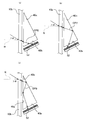
- FIG. 1 is a schematic side view showing a retroreflective window according to the first embodiment of the present invention.
- FIG. 2 is a perspective view showing the retroreflective window according to the first embodiment, and shows a rotation mechanism.
- FIG. 3 is a conceptual diagram showing the optical path of the retroreflective window according to the first embodiment, FIG. 3 (a) shows the first optical path, FIG. 3 (b) shows the second optical path, and FIG. ) Shows the third optical path, and FIG. 3D shows the fourth and fifth optical paths.
- FIG. 4 is a schematic side view when the retroreflection window according to the first embodiment is rotated up and down.
- FIG. 5 is a conceptual diagram showing an optical path when the retroreflective window according to the first embodiment is rotated up and down, FIG.
- FIG. 5 (a) shows a sixth optical path
- FIG. 5 (b) shows a seventh optical path
- FIG. 5C shows the eighth optical path
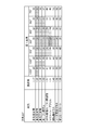
- FIG. 6 is a chart showing the relationship between the angle of the first base angle and a predetermined angle (rounded up to the nearest 1 °) when the refractive index of the prism is changed when the apex angle of the prism is 25 °. It is.
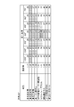
- FIG. 7 is a chart showing the relationship between the angle of the first base angle and the predetermined angle when the refractive index of the prism is changed when the apex angle of the prism is 30 °.
- FIG. 6 is a chart showing the relationship between the angle of the first base angle and a predetermined angle (rounded up to the nearest 1 °) when the refractive index of the prism is changed when the apex angle of the prism is 25 °. It is.
- FIG. 7 is a chart showing the relationship between the angle of the first base angle and the predetermined angle when the refractive
- FIG. 8 is a chart showing the relationship between the angle of the first base angle and the predetermined angle when the refractive index of the prism is changed when the apex angle of the prism is 35 °.
- FIG. 9 is a schematic side view showing the retroreflection window according to the second embodiment.
- FIG. 10 is a partial configuration diagram illustrating a retroreflective window according to the third embodiment.
- FIG. 11 is a schematic side view showing an example when a retroreflective window is used on an inclined surface.
- FIG. 1 is a schematic side view showing a retroreflection window according to the first embodiment of the present invention.
- a retroreflective window 1 according to the example shown in FIG. 1 is roughly composed of two transparent plate members 10, a peripheral end member 20, a plurality of first prisms (triangular prisms) 30, and a plurality of second prisms (first prisms). 2 triangular prisms) 40 and a plurality of switching members 50.
- the two transparent plate members 10 are transparent plate members arranged substantially in parallel with each other. These transparent plates 10 are made of, for example, a glass material, and in the state shown in FIG. 1 of the two transparent plates 10, the outdoor side becomes the first transparent plate 10a, and the indoor side has the second transparency. It becomes the board
- the peripheral end member 20 is interposed between the two transparent plate members 10 at the peripheral ends of the two transparent plate members 10. By providing the peripheral end member 20 at the peripheral end portions of the two transparent plate members 10, an internal space closed by the two transparent plate members 10 and the peripheral end member 20 is formed.
- the internal space is in a vacuum state from the viewpoint of heat insulation, but is not limited thereto, and may be filled with a gas such as air, argon, or krypton.
- the plurality of first prisms 30 are arranged between the first and second transparent plate members 10a and 10b, and are prisms each having a triangular shape in cross section (that is, a prism having a prism shape). These first prisms 30 are arranged so as to face the first transparent plate member 10a so that the first side 30a extends along the first transparent plate member 10a in a cross-sectional view. In particular, in the first embodiment, the first side 30a is provided in contact with the first transparent plate 10a.
- the second side 30b and the third side 30c of the first prism 30 extend with a predetermined angle with respect to the first side 30a.
- the second side 30b is a side located on the vertically lower side than the third side 30c.
- the first prism 30 is made of a solid glass material or resin material.
- the first prism 30 is not limited to this, and is enclosed in the prism wall constituting the outer wall of the first prism 30 and the inside of the prism wall.
- an internal member made of a transparent liquid The internal member is not limited to a transparent liquid, and may be a transparent gel or solid.
- the first transparent plate member 10a may also be used as a part of the prism wall.
- the plurality of second prisms 40 are prisms each having a triangular shape when viewed in cross section (that is, a prism having a triangular prism shape), and have the same shape and the same refractive index as the first prism 30. These second prisms 40 have a point-symmetric orientation obtained by rotating the first prism 30 by 180 °, and one second prism 40 is provided for each first prism 30.
- the 2nd prism 40 may be comprised from the prism wall and the internal member similarly to the 1st prism 30, and may be comprised by the solid member.
- each of the second prisms 40 is arranged facing the second transparent plate 10b so that the fourth side 40a is along the second transparent plate 10b.
- the fifth side 40b and the sixth side 40c of the second prism 40 extend with a predetermined angle with respect to the fourth side 40a.
- the fifth side 40b is located vertically above the sixth side 40c.
- the sixth side 40c is opposed to the third side 30c of the first prism 30 adjacent in the horizontal direction, and the fifth side 40b is adjacent in the vertical direction. 30 opposite to the second side 30b.
- the plurality of switching members 50 are members arranged to face the second side 30b of the first prism 30, and can be switched between a reflective state and a non-reflective state.
- the switching member 50 has a visible light and infrared reflectance of 70% or more in the reflection state, and a visible light and infrared reflectance of 30% or less in the non-reflection state.
- the switching member 50 has a reflective layer 51 with one surface having a visible light and infrared reflectance of 70% or more, and is provided in contact with the second side 30 b of the first prism 30. Yes.
- the other surface of the switching member 50 (the back surface side of the reflective layer 51) is an absorption layer 52 having an absorption rate of visible light and infrared rays of 70% or more, and is separated from the fifth side 40b of the second prism 40. Opposed.
- the second prism 40 is disposed with a fine gap with respect to the first prism 30 and the second transparent plate member 10b. Between these, interposition members such as minute columns and grains are interposed so that a minute gap is maintained.
- the retroreflective window 1 has a laminated structure in the order of the first prism 30, the interposed member, the second prism 40, the interposed member, and the second transparent plate 10b, and the internal space is in a vacuum state. However, it will be supported to withstand the pressure.
- FIG. 2 is a perspective view showing the retroreflective window 1 according to the first embodiment, and shows a rotating mechanism.
- the configuration two transparent plate members 10, the peripheral end member 20, the first prism 30, the second prism 40, and the switching member 50
- the rotating mechanism 60 in the retroreflective window 1 is a laminated body. (Plate) L.
- the retroreflective window 1 includes a rotating mechanism 60 in addition to the laminate L.
- the rotation mechanism 60 includes a pivot 61, a window frame 62, and a lock unit (not shown), and can rotate in the vertical direction while maintaining the left and right position of the stacked body L.
- the pivot 61 is a rotating shaft member provided at the central part of the left and right sides extending in the vertical direction of the laminate L.
- the window frame 62 is a rectangular frame member into which the laminated body L is fitted, and is provided with a rotation hole (not shown) into which the pivot 61 is inserted at the center of the left and right sides extending vertically.
- the locking means (not shown) is for fixing the laminated body L in a state of being fitted into the window frame 62.
- the user can release the locking means and rotate the laminate L around the pivot 61. After the rotation, the user locks and fixes the laminated body L to the window frame 62 by the locking means.
- the laminate L can be rotated up and down around the pivot 61, and the relative position between one plate member 10a and the other plate member 10b is maintained while maintaining the left-right position of the laminate L during rotation. A vertical rotation can be performed.
- the first prism 30 has a refractive index and triangular interior angles set so that the following optical paths OP1 to OP5 are realized.
- FIG. 3 is a conceptual diagram showing optical paths OP1 to OP5 of the retroreflective window 1 according to the first embodiment.
- FIG. 3 (a) shows the first optical path OP1
- FIG. 3 (b) shows the second optical path OP2.
- 3C shows the third optical path OP3
- FIG. 3D shows the fourth and fifth optical paths OP4 and OP5.
- the first to third optical paths OP1 to OP3 have a predetermined angle with respect to the normal line N of the first transparent plate 10a (that is, an elevation angle when used in an upright state). This is an optical path for light that enters the first transparent plate member 10a at an angle ⁇ or more and enters the triangular prism 30 from the first side 30a.
- the light that has entered at a predetermined angle ⁇ or more first reaches the second side 30b and is totally reflected by the reflection layer 51 (70% or more reflection). It reaches the third side 30c, undergoes total reflection (theoretically total reflection) at the third side 30c, and is emitted toward the sun side from the first transparent plate 10a at an angle ⁇ 1 ′ that is substantially the same as the approach angle ⁇ 1. It is an optical path.
- the light that has entered first reaches the third side 30c, undergoes total reflection (theoretically total reflection) at the third side 30c, and the first side 30a, and after total reflection (theoretically total reflection) at the first side 30a to reach the second side 30b and total reflection (reflection of 70% or more) by the reflective layer 51, the first side 30a and
- This is an optical path that undergoes total reflection (theoretically total reflection) at the third side 30c and is emitted toward the sun side from the first transparent plate member 10a at an angle ⁇ 3 ′ that is substantially the same as the approach angle ⁇ 3.
- the incident angle with respect to the third side 30c needs to be greater than or equal to the critical angle with respect to the first and second optical paths OP1 and OP2. Further, the incident angle of the third optical path OP3 to the first and third sides 30a and 30c needs to be greater than or equal to the critical angle.
- the fourth and fifth optical paths OP4 and OP5 are incident on the first transparent plate 10a with the elevation angle (for example, the angles ⁇ 4 and ⁇ 5) being less than the predetermined angle ⁇ .
- the first prism 30 totally transmits (theoretically totally transmits) light that reaches the third side 30c among the light that has entered at an elevation angle less than the predetermined angle ⁇ , so that the second transparent plate 10b (see FIG. 1). ) Through.
- FIG. 4 is a schematic side view when the retroreflective window 1 according to the first embodiment is rotated up and down.
- the second prism 40 has a refractive index and triangular inner angles so that optical paths OP4 to OP8 described later are realized.
- the fourth and fifth optical paths OP4 and OP5 are the same as those described with reference to FIG.
- FIG. 5 is a conceptual diagram showing optical paths OP6 to OP8 when the retroreflective window 1 according to the first embodiment is rotated up and down.
- FIG. 5A shows the sixth optical path OP6, and FIG. Shows the seventh optical path OP7, and FIG. 5C shows the eighth optical path OP8.
- Each of the sixth to eighth optical paths OP6 to OP8 has a second transparent plate material whose angle with respect to the normal line N of the second transparent plate material 10b (that is, an elevation angle when used in an upright state) is a predetermined angle ⁇ or more. This is an optical path for light that enters 10b and enters the second triangular prism 40 from the fourth side 40a.
- the sixth optical path OP6 is an optical path in which light that has entered at a predetermined angle ⁇ or more reaches the fifth side 40b, is emitted from the fifth side 40b, and reaches the absorption layer 52. is there.
- the seventh optical path OP7 the light that has entered at a predetermined angle ⁇ or more first reaches the sixth side 40c, and undergoes total reflection (theoretically total reflection) at the sixth side 40c.
- the eighth optical path OP8 the light that has entered at a predetermined angle ⁇ or more first reaches the sixth side 40c, and undergoes total reflection (theoretically total reflection) at the sixth side 40c.
- the incident angle to the fifth side 40b of the sixth optical path OP6 needs to be less than the critical angle.
- the incident angle to the sixth side 40c of the seventh optical path OP7 is not less than the critical angle, and the incident angle to the fifth side 40b after total reflection needs to be less than the critical angle.
- the angle of incidence on the sixth side 40c of the eighth optical path OP8 is greater than or equal to the critical angle, the angle of incidence on the fourth side 40a after total reflection is greater than or equal to the critical angle, and the fifth angle after total reflection.
- the incident angle to the side 40b of the lens needs to be less than the critical angle.
- the switching member 50 when the stacked body L is rotated up and down, the sixth to eighth optical paths OP6 to OP8 reach the absorption layer 52, so that the switching member 50 is efficiently heated by the direct light.
- the switching member 50 is heated, as shown in FIG. 4, the first prism 30 that contacts the switching member 50 is also heated, and the first transparent plate 10 a that contacts the first prism 30 is also heated. . Therefore, the 1st transparent board
- the first prism 30 and the second prism 40 have the same refractive index and the same shape. Therefore, if the prisms 30 and 40 described below are employed, the first to eighth optical paths OP1 to OP8 described above can be realized.
- an angle formed by the first side 30a and the third side 30c is referred to as an apex angle AA (see FIG. 1).
- the angle formed by the second side 30b and the third side 30c is referred to as a first base angle BA1 (see FIG. 1)
- the first An angle formed by the side 30a and the second side 30b is referred to as a second base angle BA2 (see FIG. 1).
- FIG. 6 shows that when the apex angle AA of the prisms 30 and 40 is 25 °, the angle of the first base angle BA1 and the refractive index of the prisms 30 and 40 are changed to a predetermined angle ⁇ (rounded up to 1 °).
- the first base angle BA1 is 105 °, 100 °, 95 °, 90 °, 85 °, 80 In all of ° and 75 °, the predetermined angle ⁇ is 41 °.
- the first base angle BA1 is 105 °, 100 °, 95 °, 90 °, 85 °, 80 °, and 75 °. In all, the predetermined angle ⁇ is 37 °.
- the predetermined angle ⁇ is 41 ° and the first base angle BA1 is 100 °. , 95 °, 90 °, 85 °, and 80 °, the predetermined angle ⁇ is 34 °.
- the first base angle BA1 is 105 °, 100 °, 95 °, 90 °, 85 °, 80 °, and In the order of 75 °, the predetermined angle ⁇ is 44 °, 37 °, 33 °, 33 °, 33 °, 37 °, and 44 °.
- the first base angle BA1 is 105 °, 100 °, 95 °, 90 °, 85 °, 80
- the predetermined angle ⁇ is 49 °, 41 °, 33 °, 31 °, 33 °, 41 °, and 49 ° in the order of ° and 75 °.
- the first base angle BA1 is 105 °, 100 °, 95 °, 90 °, 85 °, 80 °, and 75.
- the predetermined angle ⁇ is 54 °, 45 °, 37 °, 30 °, 37 °, 45 °, and 54 ° in the order of °.
- the first base angle BA1 is 105 °, 100 °, 95 °, 90 °, 85 °, 80 °, and 75 ° in this order.
- the predetermined angle ⁇ is 65 °, 53 °, 44 °, 35 °, 44 °, 53 °, and 65 °.
- the first base angle BA1 is in the order of 105 °, 100 °, 95 °, 90 °, 85 °, 80 °, and 75 °.
- the predetermined angle ⁇ is 73 °, 58 °, 48 °, 38 °, 48 °, 58 °, and 73 °.
- the first base angle BA1 is a predetermined angle in the order of 105 °, 100 °, 95 °, 90 °, 85 °, 80 °, and 75 °.
- ⁇ is NG (NG is 90 ° or more, meaning that it is a numerical value that does not make sense on the product. The same applies hereinafter), 70 °, 56 °, 45 °, 56 °, 70 ° And NG.
- the prisms 30 and 40 when the refractive index is approximately 1.41 and the first base angle BA1 is 90 °, the predetermined angle ⁇ is the minimum value (30 °). Therefore, it can be said that the prisms 30 and 40 preferably have a refractive index of approximately 1.41 and a first base angle BA1 of 90 °. However, due to problems such as the material of the prisms 30 and 40, the prisms 30 and 40 may not have a refractive index of approximately 1.41 and the first base angle BA1 of 90 °, and the minimum value + 10 ° (40 of the predetermined angle ⁇ ) (40 The refractive index and the internal angle may be set so that a predetermined angle ⁇ up to (°) is realized.
- the first base angle BA1 is 75 ° to 105 ° with a refractive index of 1.25
- the first base angle BA1 is 80 ° to 100 ° with the refractive indexes of 1.30 and 1.33.
- the refractive index is 1.37 and 1.41
- the first base angle BA1 is 85 ° or more and 95 ° or less
- the refractive index is 1.48 and 1.52
- the first base angle BA1 is 90 °
- the predetermined angle ⁇ can be set to 40 ° or less, which is preferable.
- the prisms 30 and 40 are not limited to those in which the refractive index and the internal angle are set so that the minimum value of the predetermined angle ⁇ + the predetermined angle ⁇ of 10 ° is realized.
- the refractive index is 1.59 or more
- the first base angle BA1 is 105 ° or more and 75 ° or less. You don't have to.
- the prisms 30 and 40 are set to have refractive indexes and angles at which the first to eighth optical paths OP1 to OP8 are realized at elevation angles within an altitude range that the sun can take in consideration of time and season in the installation area and direction. It may be.
- the prisms 30 and 40 are not limited to the refractive index and the angle setting in which the first to eighth optical paths OP1 to OP8 are realized in the entire altitude range that the sun can take, but the altitude range that the sun can take.
- the refractive index and the angle may be set such that the first to eighth optical paths OP1 to OP8 can be realized only with a part of (for example, the highest altitude in the installation area).
- FIG. 6 shows the predetermined angle ⁇ when the apex angle AA is 25 °, but when the apex angle AA changes, the value of the predetermined angle ⁇ also changes.
- FIG. 7 is a chart showing the relationship between the angle of the first base angle BA1 and the predetermined angle ⁇ when the refractive index of the prisms 30 and 40 is changed when the apex angle AA of the prisms 30 and 40 is 30 °. It is.
- the first base angle BA1 is 105 °, 100 °, 95 °, 90 °, 85 °, 80 In all of ° and 75 °, the predetermined angle ⁇ is 35 °.
- the first base angle BA1 is 105 °, 100 °, 95 °, 90 °, 85 °, 80 °, and 75 °. In all, the predetermined angle ⁇ is 30 °.
- the predetermined angle ⁇ is 33 ° and the first base angle BA1 is 100 °. , 95 °, 90 °, 85 °, and 80 °, the predetermined angle ⁇ is 27 °.
- the first base angle BA1 is 105 °, 100 °, 95 °, 90 °, 85 °, 80 °
- the predetermined angle ⁇ is 37 °, 29 °, 26 °, 26 °, 26 °, 29 °, and 37 ° in the order of 75 °.
- the first base angle BA1 is 105 °, 100 °, 95 °, 90 °, 85 °, 80
- the predetermined angle ⁇ is 41 °, 33 °, 26 °, 24 °, 26 °, 33 °, and 41 ° in the order of ° and 75 °.
- the first base angle BA1 is 105 °, 100 °, 95 °, 90 °, 85 °, 80 °, and 75.
- the predetermined angle ⁇ is 45 °, 37 °, 29 °, 22 °, 29 °, 37 °, and 45 ° in the order of °.
- the first base angle BA1 is 105 °, 100 °, 95 °, 90 °, 85 °, 80 °, and 75 ° in this order.
- the predetermined angle ⁇ is 53 °, 44 °, 35 °, 27 °, 35 °, 44 °, and 53 °.
- the first base angle BA1 is in the order of 105 °, 100 °, 95 °, 90 °, 85 °, 80 °, and 75 °.
- the predetermined angle ⁇ is 58 °, 48 °, 38 °, 30 °, 38 °, 48 °, and 58 °.
- the first base angle BA1 is a predetermined angle in the order of 105 °, 100 °, 95 °, 90 °, 85 °, 80 °, and 75 °.
- ⁇ is 70 °, 56 °, 45 °, 35 °, 45 °, 56 °, and 70 °.
- the predetermined angle ⁇ is the minimum value (22 °). Become. For this reason, when the apex angle AA is 30 °, it is preferable that the refractive index and the internal angle of the prisms 30 and 40 are set so that the predetermined angle ⁇ is 32 ° or less.
- FIG. 8 is a chart showing the relationship between the angle of the first base angle BA1 and the predetermined angle ⁇ when the refractive index of the prisms 30 and 40 is changed when the apex angle AA of the prisms 30 and 40 is 35 °. It is.
- the first base angle BA1 is 105 °, 100 °, 95 °, 90 °, 85 °, 80 In all of ° and 75 °, the predetermined angle ⁇ is 29 °.
- the first base angle BA1 is 105 °, 100 °, 95 °, 90 °, 85 °, 80 °, and 75 °. In all cases, the predetermined angle ⁇ is 23 °.
- the predetermined angle ⁇ is 27 ° and the first base angle BA1 is 100 °. , 95 °, 90 °, 85 °, and 80 °, the predetermined angle ⁇ is 21 °.
- the first base angle BA1 is 105 °, 100 °, 95 °, 90 °, 85 °, 80 °, and In the order of 75 °, the predetermined angle ⁇ is 29 °, 22 °, 19 °, 19 °, 19 °, 22 °, and 29 °.
- the first base angle BA1 is 105 °, 100 °, 95 °, 90 °, 85 °, 80
- the predetermined angle ⁇ is 33 °, 26 °, 19 °, 17 °, 19 °, 26 °, and 33 ° in the order of ° and 75 °.
- the first base angle BA1 is 105 °, 100 °, 95 °, 90 °, 85 °, 80 °, and 75.
- the predetermined angle ⁇ is 37 °, 29 °, 22 °, 14 °, 22 °, 29 °, and 37 ° in the order of °.
- the first base angle BA1 is 105 °, 100 °, 95 °, 90 °, 85 °, 80 °, and 75 ° in this order.
- the predetermined angle ⁇ is 44 °, 35 °, 27 °, 19 °, 27 °, 35 °, and 44 °.
- the first base angle BA1 is in the order of 105 °, 100 °, 95 °, 90 °, 85 °, 80 °, and 75 °.
- the predetermined angle ⁇ is 48 °, 38 °, 30 °, 22 °, 30 °, 38 °, and 48 °.
- the first base angle BA1 is a predetermined angle in the order of 105 °, 100 °, 95 °, 90 °, 85 °, 80 °, and 75 °.
- ⁇ is 56 °, 45 °, 35 °, 27 °, 35 °, 45 °, and 56 °.
- the predetermined angle ⁇ is a minimum value (14 °). Become. For this reason, when the apex angle AA is 30 °, it is preferable that the refractive indexes and interior angles of the prisms 30 and 40 are set so that the predetermined angle ⁇ is 24 ° or less.
- the retroreflective window 1 realizes the first to fifth optical paths OP1 to OP5 shown in FIG. 3 by setting the refractive index and the internal angle of the first prism 30. It has become so.
- the light that has entered the first prism 30 at a predetermined angle ⁇ or more with respect to the first transparent plate 10a forms the first to third optical paths OP1 to OP3, and reaches the first angle at substantially the same angle as when entering. 1 is emitted through the transparent plate 10a and is not reflected to the ground side.
- part of the light that has entered the first prism 30 at a angle less than the predetermined angle ⁇ with respect to the first transparent plate 10a forms fourth and fifth optical paths OP4 and OP5. For this reason, light that has entered the first prism 30 at a angle less than the predetermined angle ⁇ and has reached the third side 30c is totally transmitted and emitted from the second transparent plate member 10b to the indoor side.
- the light that has entered the first prism 30 at a angle less than the predetermined angle ⁇ the light that has reached the second side 30b undergoes total reflection (total reflection at the reflection layer 51) and total transmission, and part of the light passes through the chamber. The light is emitted to the inside, and the rest is emitted to the outdoor side.
- the retroreflective window 1 has the second prism 40 on the outdoor side as shown in FIG. In this state, the retroreflective window 1 realizes the fourth and fifth optical paths OP4 and OP5 shown in FIG. 3 and the sixth to eighth optical paths OP6 to OP8 shown in FIG.
- light that has entered the second prism 40 at a predetermined angle ⁇ or more with respect to the second transparent plate 10b forms sixth to eighth optical paths OP6 to OP8, and collects sunlight in the absorption layer 52. Will be.
- plate material 10a can be heated through the 1st prism 30, and the heating effect can be brought about indoor side.
- part of the light that has entered the second prism 40 at a angle less than the predetermined angle ⁇ with respect to the second transparent plate member 10b forms fourth and fifth optical paths OP4 and OP5. For this reason, the light that has entered the second prism 40 at a angle less than the predetermined angle ⁇ is totally transmitted and emitted from the first transparent plate member 10a to the indoor side unless the switching member 50 blocks the light.
- the switching member 50 since the switching member 50 is in contact with the first prism 30 and the first prism 30 is in contact with the first transparent plate 10 a, the sun collected on the absorption layer 52.
- a method of heating the first transparent plate 10a using light is employed.
- the present invention is not limited thereto, and a heat medium may be circulated in the absorption layer 52, and the heat medium may be heated and used for other devices.
- the switching member 50 and the first prism 30 may not be in contact with each other, and the first prism 30 and the first transparent plate member 10a may not be in contact with each other.
- the first prism 30 transmits light incident at a predetermined angle ⁇ or more when the switching member 50 is in the reflective state. 3 is reflected from the third side 30c, and is emitted from the first transparent plate 10a at substantially the same angle as that at the time of entering, and transmits light that reaches the third side 30c out of the light having entered at a predetermined angle ⁇ or less. It is made to emit from the 2nd transparent board
- the switching member 50 can be switched not only to the reflecting state but also to the non-reflecting state, not only the direct light is reflected to the sun side but also the non-reflecting state can be used to improve the utilization of the direct light. Therefore, it is possible to provide the retroreflective window 1 that can block the direct light and reflect it to the sun while maintaining the viewability, and can improve the usability of the direct light.
- the switching member 50 includes a reflection layer 51 and an absorption layer 52
- the switching member 50 includes a reflection layer 51 and an absorption layer 52.
- the rotation mechanism 60 can rotate the stacked body L including the first prism 30 and the like in the vertical direction. It can be switched between the reflection state and the absorption state. For this reason, it is possible to switch between a state in which the direct light is blocked by the rotation mechanism 60 and reflected to the sun side, and a state in which the direct light is absorbed and used for indoor heating and the like, and the usability of the direct light can be improved. it can.
- the retroreflection window according to the second embodiment is the same as that of the first embodiment, but a part of the configuration is different.
- the same or similar elements as those in the first embodiment are denoted by the same reference numerals and description thereof is omitted.
- FIG. 9 is a schematic side view showing the retroreflection window according to the second embodiment.
- the switching member 50 has a temperature environment, a light irradiation environment, or a whitened reflection state and a transparent non-reflection state (transmission state). It is comprised by the member switched according to a voltage application condition.
- the direct light can be reflected to the sun side when the switching member 50 becomes white turbid and becomes a reflective state, and the direct light can be taken into the indoor side when the switching member 50 becomes transparent and becomes a non-reflective state.
- the transmissive state is described as the non-reflective state, but the transmissive state is not necessarily limited to the transmissive state.
- the switching member 50 is composed of materials such as thermochromic, photochromic, and electrochromic materials that change color in response to irradiation with ultraviolet rays or the like at high temperatures, and parts such as electronic paper.
- materials such as thermochromic, photochromic, and electrochromic materials that change color in response to irradiation with ultraviolet rays or the like at high temperatures
- parts such as electronic paper.
- um glass which is a kind of electrochromic, becomes transparent when a voltage is applied, and becomes turbid and reflects light when no voltage is applied.
- many technologies used for electronic paper such as a magnetophoretic monochrome switching display type, can also be used.
- the switching member 50 is not limited to the above materials, and may be constituted by a transparent tube and a specific liquid.
- some liquids having LCST (Lower Critical Solution Temperature) properties become transparent below the phase separation temperature and become cloudy above the phase separation temperature (cloud point).
- LCST Lower Critical Solution Temperature
- an aqueous solution of N-isopropylacrylamide has a cloud point near the body temperature, has a transmittance of about 100% below it, and has a transmittance of about 0% above it.
- the switching member 50 may be configured by sealing such a liquid in a transparent tube.
- the switching member 50 becomes clouded in the retroreflective window 2 according to the second embodiment and is in a reflective state.
- the light that has entered the first prism 30 at a predetermined angle ⁇ or more with respect to the first transparent plate 10a is substantially the same as the entry angle, as in the first embodiment.
- the light is emitted through 10a and is not reflected to the ground side.
- the light that has entered the first prism 30 at a angle less than the predetermined angle ⁇ with respect to the first transparent plate 10a is totally transmitted when it reaches the third side 30c. 10b is emitted indoors.
- the switching member 50 becomes transparent and becomes a non-reflective state.
- the light that has entered the first prism 30 at a predetermined angle ⁇ or more with respect to the first transparent plate 10 a reaches the switching member 50, it passes through the second prism 40 and passes through the second prism 40. It will be radiate
- the direct light can be blocked and reflected to the sun side while maintaining the viewability, It is possible to provide the retroreflective window 2 that can improve the utilization of direct light.
- the switching member 50 is configured by a member that can be switched between a white turbid reflection state and a transparent non-reflection state according to a temperature environment or a voltage application state.
- a white turbid reflection state When the light is cut off and reflected on the sun side and made transparent, direct light can be taken into the room. Therefore, the usability of direct light can be increased.
- the retroreflection window according to the third embodiment is the same as that of the first embodiment, but a part of the configuration is different.
- the same or similar elements as those in the first embodiment are denoted by the same reference numerals and description thereof is omitted.
- FIG. 10 is a partial configuration diagram showing the retroreflective window 3 according to the third embodiment.
- the switching member 50 has shown the state seen from the lamination direction of the laminated body L.
- FIG. 10 the retroreflective window 3 according to the third embodiment includes operation mechanisms 70 and 80 for switching the switching member 50 between a reflective state and a non-reflective state.
- operation mechanisms 70 and 80 for switching the switching member 50 between a reflective state and a non-reflective state.
- two operation mechanisms 70 and 80 including a first operation mechanism 70 and a second operation mechanism 80 are provided will be described.
- only one of the retroreflection windows 3 according to the third embodiment is described.
- the operation mechanisms 70 and 80 may be included.
- the switching member 50 is equipped with the transparent hollow member 53, and is in the reflective state by which the white or silver liquid was enclosed in the hollow member 53, and the non-reflective state by which the transparent liquid was enclosed. , Which can be switched.
- Such a switching member 50 can inject a transparent liquid from one end side of the hollow member 53 and can inject a white or silver liquid from the other end side.
- the switching member 50 is provided with a jelly-like gel pig 54 that separates two liquids inside the hollow member 53.
- the first operating mechanism 70 is for switching the switching member 50 between a reflective state and a non-reflective state by a user operation, and includes an upper pulley 71, a lower pulley 72, a ladder cord 73, and an operation unit 74.
- a plurality of liquid storage containers 75 and a plurality of flexible tubes 76 are provided.
- the upper pulley 71 and the lower pulley 72 are pulley members provided on the upper side and the lower side of the retroreflective window 3, respectively.
- the ladder cord 73 is an endless string member wound around the upper pulley 71 and the lower pulley 72.
- An operation unit 74 and a plurality of liquid storage containers 75 are attached to the ladder code 73.
- the operation unit 74 includes, for example, an internal magnet 74a and an external magnet 74b.
- the internal magnet 74 a is a magnet member disposed in an internal space formed by the two plate members 10 and the peripheral end member 20, and is connected to the ladder cord 73.
- the external magnet 74b is attracted to the internal magnet 74a via the second transparent plate member 10b located on the indoor side.
- the inner magnet 74a and the outer magnet 74b are composed of strong magnets such as neodymium magnets, for example.
- the liquid storage container 75 is a container that is provided with a plurality of liquid storage containers 75 arranged vertically along the ladder cord 73 extending vertically. The same number of liquid storage containers 75 as the number of switching members 50 are provided, and each liquid storage container 75 is connected to one end of each switching member 50 through a flexible tube 76 having flexibility.
- the second operation mechanism 80 is for automatically switching the switching member 50 between the reflective state and the non-reflective state regardless of the user's operation, and includes a cord member 81, a weight W, and a shape memory alloy spring 82.
- the cord member 81 is a string member in which an upper end is attached to the triangular protrusion P protruding from the first transparent plate member 10a and a weight W is attached to the lower end.
- the shape memory alloy spring 82 is a member that can expand and contract according to the ambient temperature.
- the shape memory alloy spring 82 is interposed between the cord members 81 and is housed in the grease case 83.
- the inside of the grease case 83 is filled with heat transfer grease G. Further, the grease case 83 is provided in contact with one of the transparent plate members 10a.
- the liquid storage container 84 is a container in which a plurality of liquid storage containers 84 are provided in the vertical direction along the cord member 81 extending in the vertical direction, and white or silver liquid is stored.
- the same number of liquid storage containers 84 as the number of switching members 50 are provided, and each liquid storage container 84 is connected to the other end of each switching member 50 through a flexible tube 85 having flexibility.
- the outside air temperature is high in summer.
- the outside air temperature is transmitted from the first transparent plate member 10a to the shape memory alloy spring 82 through the grease case 83 and the heat transfer grease G, and the shape memory alloy spring 82 is in a tension state.
- the shape memory alloy spring 82 is in a tension state, the cord member 81 is pulled up and the plurality of liquid storage containers 84 are also pulled up.
- the white or silver liquid in the liquid storage container 84 pushes the gel pig 54 toward one end, and the switching member 50 is in a reflective state.
- the switching member 50 is in the reflective state, the direct light is reflected to the sun side as in the first and second embodiments.
- the outside air temperature is low in winter.
- the outside air temperature is transmitted from the first transparent plate member 10a to the shape memory alloy spring 82 through the grease case 83 and the heat transfer grease G, and the shape memory alloy spring 82 is in a relaxed state.
- the shape memory alloy spring 82 is in a relaxed state, the cord member 81 is lowered and the positions of the plurality of liquid storage containers 84 are also lowered.
- the transparent liquid in the liquid storage container 75 pushes the gel pig 54 to the other end side, and the switching member 50 becomes non-reflective.
- the switching member 50 is in a non-reflective state, direct light is taken into the room as in the second embodiment.
- the direct light can be blocked and reflected to the sun side while maintaining the viewability, It is possible to provide the retroreflective window 3 that can improve the utilization of direct light.
- the switching member 50 is configured by the transparent hollow member 53, and switches between a reflective state in which white or silver liquid is sealed and a non-reflective state in which transparent liquid is sealed. Therefore, when the white or silver liquid is sealed, the direct light is blocked and reflected to the sun side, and when the transparent liquid is sealed, the direct light can be taken into the room. Therefore, the usability of direct light can be increased.
- the present invention has been described based on the embodiments, but the present invention is not limited to the above-described embodiments, and may be modified without departing from the spirit of the present invention, and may be appropriately changed within a possible range. These techniques may be combined. Furthermore, known or well-known techniques may be combined within a possible range.
- FIG. 11 is a schematic side view showing an example when the retroreflective windows 1 to 3 are used on an inclined surface.
- the retroreflective windows 1 to 3 may be used on an inclined surface inclined to the north side in Japan, for example. Even in such a case, the optical paths OP1 to OP8 and the like can be realized from the relationship with the predetermined angle at the time of elevation.
- the retroreflective windows 1 to 3 have a two-layer structure of the first transparent plate member 10a and the second transparent plate member 10b. It may be.
- the white turbid reflection state and the transparent non-reflection state are switched.
- the present invention is not limited to this, and the white turbid reflection state and the black absorption state (absorption rate of 70% or more) ) May be switched.
- the switching member 50 may be composed of parts such as magnetophoretic electronic paper.
- the switching member 50 is brought into contact with the second prism 40 or the heating medium is heated using the switching member 50 to change the direct light into heat. It can be taken into the room.
- the third embodiment may be configured to switch between a reflection state in which white or silver liquid is sealed and an absorption state in which black liquid is sealed (absorption rate of 70% or more).
- the liquid storage container 84 is filled with black liquid.
- retroreflective window 10a first transparent plate 10b: second transparent plate 30: first prism (triangular prism) 30a: first side 30b: second side 30c: third side 40: second prism (second triangular prism) 40a: 4th side 40b: 5th side 40c: 6th side 50: Switching member 51: Reflective layer 52: Absorption layer 53: Hollow member 60: Rotating mechanism L: Laminate (flat plate) N: normal lines OP1 to OP8: first to eighth optical paths ⁇ : predetermined angle
Landscapes
- Physics & Mathematics (AREA)
- Engineering & Computer Science (AREA)
- Structural Engineering (AREA)
- Civil Engineering (AREA)
- General Physics & Mathematics (AREA)
- Optics & Photonics (AREA)
- Architecture (AREA)
- Optical Elements Other Than Lenses (AREA)
Abstract
Description
10a :第1の透明性板材
10b :第2の透明性板材
30 :第1プリズム(三角柱プリズム)
30a :第1の辺
30b :第2の辺
30c :第3の辺
40 :第2プリズム(第2三角柱プリズム)
40a :第4の辺
40b :第5の辺
40c :第6の辺
50 :切替部材
51 :反射層
52 :吸収層
53 :中空部材
60 :回転機構
L :積層体(平板体)
N :法線
OP1~OP8 :第1~第8光路
α :所定角度
Claims (4)
- 互いに略平行配置される第1及び第2の透明性板材と、
前記第1及び第2の透明性板材の間に配置されると共に、断面視して第1の透明性板材に沿う第1の辺と前記第1の辺に対して角度を有する第2及び第3の辺からなる透明性の三角柱プリズムと、
前記第2及び第3の辺のうち下方側の辺となる第2の辺に対向して設置され、可視光及び赤外線の反射率が70%以上となる反射状態と、可視光及び赤外線の反射率が30%以下となる非反射状態とで切替可能な切替部材と、を備え、
前記三角柱プリズムは、前記切替部材が反射状態であるときに、
前記第1の透明性板材の法線に対する角度が所定角度以上で前記第1の透明性板材に入射して前記第1の辺から当該三角柱プリズム内に進入した光を、前記切替部材及び前記第3の辺での反射を経て、進入時と略同じ角度で前記第1の透明性板材から出射させ、
前記法線に対する角度が所定角度未満で前記第1の透明性板材に入射して前記第1の辺から当該三角柱プリズム内に進入した光のうち、前記第3の辺に到達するものを透過させて、前記第2の透明性板材から出射させる
再帰反射窓。 - 断面視状態で、前記三角柱プリズムと同一形状であり、前記第2の透明性板材に接する第4の辺と前記第4の辺に対して角度を有する第5及び第6の辺からなり、前記三角柱プリズムと点対称となる向きに配置された透明性の第2三角柱プリズムと、
前記第1及び第2の透明性板材、前記三角柱プリズム、前記第2三角柱プリズム、及び前記切替部材を有した平板体の左右位置を維持したまま上下方向に回転可能とする回転機構と、をさらに備え、
前記切替部材は、
前記三角柱プリズムの前記第2の辺に接して設けられ、可視光及び赤外線の反射率が70%以上となる反射層と、
当該反射層の裏面側に設けられて前記第2三角柱プリズムの前記第5の辺に対して離間すると共に可視光及び赤外線の吸収率が70%以上となる吸収層と、を有し、
前記回転機構による回転によって、前記反射状態と、前記非反射状態である吸収状態とで切り替えられる
請求項1に記載の再帰反射窓。 - 前記切替部材は、白濁化した前記反射状態と透明化した非反射状態とが、温度環境、光照射環境、若しくは電圧印加状況に応じて切り替えられる部材、又は白濁化した前記反射状態と黒色化した非反射状態とが、磁気泳動式によって切り替えられる部材によって構成されている
請求項1に記載の再帰反射窓。 - 前記切替部材は、透明性の中空部材によって構成され、白色又は銀色液体が封入された前記反射状態と、透明性液体又は黒色系液体が封入された前記非反射状態とが切替可能とされている
請求項1に記載の再帰反射窓。
Priority Applications (5)
| Application Number | Priority Date | Filing Date | Title |
|---|---|---|---|
| AU2018407796A AU2018407796B2 (en) | 2018-02-09 | 2018-12-10 | Retroreflective window |
| US16/968,845 US11319749B2 (en) | 2018-02-09 | 2018-12-10 | Retroreflective window |
| DE112018007050.6T DE112018007050B4 (de) | 2018-02-09 | 2018-12-10 | Retroreflektierendes Fenster |
| CN201880088636.2A CN111684317B (zh) | 2018-02-09 | 2018-12-10 | 回射窗 |
| GB2012393.1A GB2584248B (en) | 2018-02-09 | 2018-12-10 | Retroreflective window |
Applications Claiming Priority (2)
| Application Number | Priority Date | Filing Date | Title |
|---|---|---|---|
| JP2018-021509 | 2018-02-09 | ||
| JP2018021509A JP6670866B2 (ja) | 2018-02-09 | 2018-02-09 | 再帰反射窓 |
Publications (1)
| Publication Number | Publication Date |
|---|---|
| WO2019155754A1 true WO2019155754A1 (ja) | 2019-08-15 |
Family
ID=67548415
Family Applications (1)
| Application Number | Title | Priority Date | Filing Date |
|---|---|---|---|
| PCT/JP2018/045339 Ceased WO2019155754A1 (ja) | 2018-02-09 | 2018-12-10 | 再帰反射窓 |
Country Status (7)
| Country | Link |
|---|---|
| US (1) | US11319749B2 (ja) |
| JP (1) | JP6670866B2 (ja) |
| CN (1) | CN111684317B (ja) |
| AU (1) | AU2018407796B2 (ja) |
| DE (1) | DE112018007050B4 (ja) |
| GB (1) | GB2584248B (ja) |
| WO (1) | WO2019155754A1 (ja) |
Families Citing this family (4)
| Publication number | Priority date | Publication date | Assignee | Title |
|---|---|---|---|---|
| JP7039352B2 (ja) * | 2018-03-27 | 2022-03-22 | 矢崎エナジーシステム株式会社 | 多段型プリズム窓 |
| JP7043342B2 (ja) * | 2018-05-16 | 2022-03-29 | 矢崎エナジーシステム株式会社 | 多段型プリズム窓 |
| CN113324934B (zh) * | 2021-06-16 | 2022-03-01 | 深圳市英宝硕科技有限公司 | 一种气体检测定位系统 |
| CN117091094A (zh) * | 2023-08-09 | 2023-11-21 | 绿城建设管理集团有限公司 | 一种地下室采光发光柱 |
Citations (6)
| Publication number | Priority date | Publication date | Assignee | Title |
|---|---|---|---|---|
| JPS58114384U (ja) * | 1982-01-28 | 1983-08-04 | 松下電工株式会社 | 回転窓 |
| JPS6080293U (ja) * | 1983-11-08 | 1985-06-04 | 旭硝子株式会社 | 遮熱、蓄熱ル−バ− |
| JP2012003024A (ja) * | 2010-06-16 | 2012-01-05 | Sony Corp | 光学体、窓材、建具、日射遮蔽装置、および建築物 |
| WO2012095847A1 (en) * | 2011-01-10 | 2012-07-19 | Pythagoras Solar Inc. | A window |
| JP2013508582A (ja) * | 2009-10-21 | 2013-03-07 | ピタゴラス ソーラー インコーポレーテッド | 窓 |
| JP2013080142A (ja) * | 2011-10-05 | 2013-05-02 | Goyo Paper Working Co Ltd | 遮光フィルム及びその製造方法 |
Family Cites Families (14)
| Publication number | Priority date | Publication date | Assignee | Title |
|---|---|---|---|---|
| US4365620A (en) * | 1978-08-25 | 1982-12-28 | Bliamptis Emmanuel E | Reversible window for solar heating and cooling |
| JPS597852A (ja) * | 1982-07-01 | 1984-01-17 | Matsushita Electric Ind Co Ltd | 反射吸熱窓 |
| US5686979A (en) * | 1995-06-26 | 1997-11-11 | Minnesota Mining And Manufacturing Company | Optical panel capable of switching between reflective and transmissive states |
| JP2003202159A (ja) | 2001-10-31 | 2003-07-18 | Kenji Ishii | 全反射と鏡面反射を組み合わせた選択透過反射材 |
| JP4890800B2 (ja) * | 2005-06-29 | 2012-03-07 | スリーエム イノベイティブ プロパティズ カンパニー | 透明波長選択性再帰反射体 |
| JP5183559B2 (ja) * | 2009-04-16 | 2013-04-17 | 五洋紙工株式会社 | 角度選択性遮光シート及び該シートからなる日除け |
| JP2011186414A (ja) | 2010-02-12 | 2011-09-22 | Sony Corp | 光学素子、日射遮蔽装置、建具、窓材および光学素子の製造方法 |
| JP2014142669A (ja) | 2010-02-12 | 2014-08-07 | Dexerials Corp | 光学素子、日射遮蔽装置、建具、窓材および光学素子の製造方法 |
| JP6074128B2 (ja) * | 2010-04-15 | 2017-02-01 | デクセリアルズ株式会社 | 光学体およびその製造方法、日射遮蔽部材、窓材、内装部材ならびに建具 |
| US20150285454A1 (en) * | 2012-11-16 | 2015-10-08 | President And Fellows Of Harvard College | Dynamic Light Control System And Methods For Producing The Same |
| WO2016147175A2 (en) * | 2015-03-18 | 2016-09-22 | Gauzy Ltd. | Solar reflective and absorptive electrically-switchable film and glazing |
| WO2017151202A2 (en) * | 2015-12-08 | 2017-09-08 | 3M Innovative Properties Company | Prismatic retroreflective sheeting including infrared absorbing material |
| JP6730871B2 (ja) * | 2016-04-07 | 2020-07-29 | デクセリアルズ株式会社 | 光学体、窓材及びロールカーテン |
| JP7091132B2 (ja) * | 2018-05-09 | 2022-06-27 | 矢崎エナジーシステム株式会社 | 外壁材及びその製造方法 |
-
2018
- 2018-02-09 JP JP2018021509A patent/JP6670866B2/ja not_active Expired - Fee Related
- 2018-12-10 GB GB2012393.1A patent/GB2584248B/en not_active Expired - Fee Related
- 2018-12-10 WO PCT/JP2018/045339 patent/WO2019155754A1/ja not_active Ceased
- 2018-12-10 DE DE112018007050.6T patent/DE112018007050B4/de not_active Expired - Fee Related
- 2018-12-10 CN CN201880088636.2A patent/CN111684317B/zh not_active Expired - Fee Related
- 2018-12-10 US US16/968,845 patent/US11319749B2/en active Active
- 2018-12-10 AU AU2018407796A patent/AU2018407796B2/en not_active Ceased
Patent Citations (6)
| Publication number | Priority date | Publication date | Assignee | Title |
|---|---|---|---|---|
| JPS58114384U (ja) * | 1982-01-28 | 1983-08-04 | 松下電工株式会社 | 回転窓 |
| JPS6080293U (ja) * | 1983-11-08 | 1985-06-04 | 旭硝子株式会社 | 遮熱、蓄熱ル−バ− |
| JP2013508582A (ja) * | 2009-10-21 | 2013-03-07 | ピタゴラス ソーラー インコーポレーテッド | 窓 |
| JP2012003024A (ja) * | 2010-06-16 | 2012-01-05 | Sony Corp | 光学体、窓材、建具、日射遮蔽装置、および建築物 |
| WO2012095847A1 (en) * | 2011-01-10 | 2012-07-19 | Pythagoras Solar Inc. | A window |
| JP2013080142A (ja) * | 2011-10-05 | 2013-05-02 | Goyo Paper Working Co Ltd | 遮光フィルム及びその製造方法 |
Also Published As
| Publication number | Publication date |
|---|---|
| JP2019139040A (ja) | 2019-08-22 |
| GB202012393D0 (en) | 2020-09-23 |
| US11319749B2 (en) | 2022-05-03 |
| JP6670866B2 (ja) | 2020-03-25 |
| GB2584248B (en) | 2022-06-08 |
| AU2018407796A1 (en) | 2020-08-27 |
| DE112018007050T5 (de) | 2020-10-22 |
| CN111684317A (zh) | 2020-09-18 |
| GB2584248A (en) | 2020-11-25 |
| CN111684317B (zh) | 2022-04-26 |
| DE112018007050B4 (de) | 2022-12-29 |
| AU2018407796B2 (en) | 2021-04-15 |
| US20210017810A1 (en) | 2021-01-21 |
Similar Documents
| Publication | Publication Date | Title |
|---|---|---|
| WO2019155754A1 (ja) | 再帰反射窓 | |
| CA2693022C (en) | Thermally switched reflective optical shutter | |
| CN101910891B (zh) | 热控开关吸收性百叶窗 | |
| US20140047783A1 (en) | Window with modifiable transparency | |
| US9904136B2 (en) | Light masked smart glazing | |
| KR20210045410A (ko) | 전기 연결 구성을 위한 비대칭 판유리 오프셋이 있는 프라이버시 글레이징 구조체 | |
| WO1995011127A1 (en) | Electrically activated thermochromic optical shutters | |
| JP2009541623A (ja) | 角度選択的な透過性を有する日光防御装置 | |
| WO2014054574A1 (ja) | 採光フィルム、採光フィルムの原反ロール、窓ガラス、ロールスクリーンおよび採光ルーバー | |
| AU2018394843B2 (en) | Solar energy utilization device | |
| CN102027183A (zh) | 太阳能电池板窗户 | |
| US11572735B2 (en) | Multistage prism window | |
| JP5003354B2 (ja) | 積層体及びそれを用いる光学特性制御方法 | |
| WO2019220823A1 (ja) | プリズム窓及び多段型プリズム窓 | |
| US11834899B2 (en) | Multi-stage prism window | |
| KR20200006400A (ko) | 태양광 차단 투명 블라인드 장치 | |
| ES2235635B1 (es) | Combinacion de liquidos utilizable en pantallas de oscurecimiento. | |
| JPWO2016009589A1 (ja) | 面状光学素子、照明装置及び建材 |
Legal Events
| Date | Code | Title | Description |
|---|---|---|---|
| 121 | Ep: the epo has been informed by wipo that ep was designated in this application |
Ref document number: 18905318 Country of ref document: EP Kind code of ref document: A1 |
|
| ENP | Entry into the national phase |
Ref document number: 202012393 Country of ref document: GB Kind code of ref document: A Free format text: PCT FILING DATE = 20181210 |
|
| ENP | Entry into the national phase |
Ref document number: 2018407796 Country of ref document: AU Date of ref document: 20181210 Kind code of ref document: A |
|
| 122 | Ep: pct application non-entry in european phase |
Ref document number: 18905318 Country of ref document: EP Kind code of ref document: A1 |