WO2019155984A1 - 建設機械 - Google Patents
建設機械 Download PDFInfo
- Publication number
- WO2019155984A1 WO2019155984A1 PCT/JP2019/003503 JP2019003503W WO2019155984A1 WO 2019155984 A1 WO2019155984 A1 WO 2019155984A1 JP 2019003503 W JP2019003503 W JP 2019003503W WO 2019155984 A1 WO2019155984 A1 WO 2019155984A1
- Authority
- WO
- WIPO (PCT)
- Prior art keywords
- blade
- pilot pressure
- pilot
- pressure
- command
- Prior art date
- Legal status (The legal status is an assumption and is not a legal conclusion. Google has not performed a legal analysis and makes no representation as to the accuracy of the status listed.)
- Ceased
Links
Images


Classifications
-
- E—FIXED CONSTRUCTIONS
- E02—HYDRAULIC ENGINEERING; FOUNDATIONS; SOIL SHIFTING
- E02F—DREDGING; SOIL-SHIFTING
- E02F3/00—Dredgers; Soil-shifting machines
- E02F3/04—Dredgers; Soil-shifting machines mechanically-driven
- E02F3/76—Graders, bulldozers, or the like with scraper plates or ploughshare-like elements; Levelling scarifying devices
- E02F3/80—Component parts
- E02F3/84—Drives or control devices therefor, e.g. hydraulic drive systems
- E02F3/844—Drives or control devices therefor, e.g. hydraulic drive systems for positioning the blade, e.g. hydraulically
-
- E—FIXED CONSTRUCTIONS
- E02—HYDRAULIC ENGINEERING; FOUNDATIONS; SOIL SHIFTING
- E02F—DREDGING; SOIL-SHIFTING
- E02F9/00—Component parts of dredgers or soil-shifting machines, not restricted to one of the kinds covered by groups E02F3/00 - E02F7/00
- E02F9/20—Drives; Control devices
- E02F9/22—Hydraulic or pneumatic drives
- E02F9/2203—Arrangements for controlling the attitude of actuators, e.g. speed, floating function
-
- E—FIXED CONSTRUCTIONS
- E02—HYDRAULIC ENGINEERING; FOUNDATIONS; SOIL SHIFTING
- E02F—DREDGING; SOIL-SHIFTING
- E02F3/00—Dredgers; Soil-shifting machines
- E02F3/04—Dredgers; Soil-shifting machines mechanically-driven
- E02F3/28—Dredgers; Soil-shifting machines mechanically-driven with digging tools mounted on a dipper- or bucket-arm, i.e. there is either one arm or a pair of arms, e.g. dippers, buckets
- E02F3/36—Component parts
- E02F3/42—Drives for dippers, buckets, dipper-arms or bucket-arms
- E02F3/43—Control of dipper or bucket position; Control of sequence of drive operations
- E02F3/435—Control of dipper or bucket position; Control of sequence of drive operations for dipper-arms, backhoes or the like
- E02F3/437—Control of dipper or bucket position; Control of sequence of drive operations for dipper-arms, backhoes or the like providing automatic sequences of movements, e.g. linear excavation, keeping dipper angle constant
-
- E—FIXED CONSTRUCTIONS
- E02—HYDRAULIC ENGINEERING; FOUNDATIONS; SOIL SHIFTING
- E02F—DREDGING; SOIL-SHIFTING
- E02F3/00—Dredgers; Soil-shifting machines
- E02F3/04—Dredgers; Soil-shifting machines mechanically-driven
- E02F3/96—Dredgers; Soil-shifting machines mechanically-driven with arrangements for alternate or simultaneous use of different digging elements
- E02F3/963—Arrangements on backhoes for alternate use of different tools
- E02F3/964—Arrangements on backhoes for alternate use of different tools of several tools mounted on one machine
-
- E—FIXED CONSTRUCTIONS
- E02—HYDRAULIC ENGINEERING; FOUNDATIONS; SOIL SHIFTING
- E02F—DREDGING; SOIL-SHIFTING
- E02F9/00—Component parts of dredgers or soil-shifting machines, not restricted to one of the kinds covered by groups E02F3/00 - E02F7/00
- E02F9/20—Drives; Control devices
- E02F9/22—Hydraulic or pneumatic drives
- E02F9/2221—Control of flow rate; Load sensing arrangements
- E02F9/2232—Control of flow rate; Load sensing arrangements using one or more variable displacement pumps
- E02F9/2235—Control of flow rate; Load sensing arrangements using one or more variable displacement pumps including an electronic controller
-
- E—FIXED CONSTRUCTIONS
- E02—HYDRAULIC ENGINEERING; FOUNDATIONS; SOIL SHIFTING
- E02F—DREDGING; SOIL-SHIFTING
- E02F9/00—Component parts of dredgers or soil-shifting machines, not restricted to one of the kinds covered by groups E02F3/00 - E02F7/00
- E02F9/20—Drives; Control devices
- E02F9/22—Hydraulic or pneumatic drives
- E02F9/226—Safety arrangements, e.g. hydraulic driven fans, preventing cavitation, leakage, overheating
-
- E—FIXED CONSTRUCTIONS
- E02—HYDRAULIC ENGINEERING; FOUNDATIONS; SOIL SHIFTING
- E02F—DREDGING; SOIL-SHIFTING
- E02F9/00—Component parts of dredgers or soil-shifting machines, not restricted to one of the kinds covered by groups E02F3/00 - E02F7/00
- E02F9/20—Drives; Control devices
- E02F9/22—Hydraulic or pneumatic drives
- E02F9/2278—Hydraulic circuits
- E02F9/2292—Systems with two or more pumps
-
- E—FIXED CONSTRUCTIONS
- E02—HYDRAULIC ENGINEERING; FOUNDATIONS; SOIL SHIFTING
- E02F—DREDGING; SOIL-SHIFTING
- E02F9/00—Component parts of dredgers or soil-shifting machines, not restricted to one of the kinds covered by groups E02F3/00 - E02F7/00
- E02F9/20—Drives; Control devices
- E02F9/22—Hydraulic or pneumatic drives
- E02F9/2278—Hydraulic circuits
- E02F9/2296—Systems with a variable displacement pump
-
- E—FIXED CONSTRUCTIONS
- E02—HYDRAULIC ENGINEERING; FOUNDATIONS; SOIL SHIFTING
- E02F—DREDGING; SOIL-SHIFTING
- E02F3/00—Dredgers; Soil-shifting machines
- E02F3/04—Dredgers; Soil-shifting machines mechanically-driven
- E02F3/76—Graders, bulldozers, or the like with scraper plates or ploughshare-like elements; Levelling scarifying devices
- E02F3/7609—Scraper blade mounted forwardly of the tractor on a pair of pivoting arms which are linked to the sides of the tractor, e.g. bulldozers
-
- E—FIXED CONSTRUCTIONS
- E02—HYDRAULIC ENGINEERING; FOUNDATIONS; SOIL SHIFTING
- E02F—DREDGING; SOIL-SHIFTING
- E02F9/00—Component parts of dredgers or soil-shifting machines, not restricted to one of the kinds covered by groups E02F3/00 - E02F7/00
- E02F9/20—Drives; Control devices
- E02F9/2004—Control mechanisms, e.g. control levers
-
- E—FIXED CONSTRUCTIONS
- E02—HYDRAULIC ENGINEERING; FOUNDATIONS; SOIL SHIFTING
- E02F—DREDGING; SOIL-SHIFTING
- E02F9/00—Component parts of dredgers or soil-shifting machines, not restricted to one of the kinds covered by groups E02F3/00 - E02F7/00
- E02F9/20—Drives; Control devices
- E02F9/22—Hydraulic or pneumatic drives
- E02F9/2221—Control of flow rate; Load sensing arrangements
- E02F9/2225—Control of flow rate; Load sensing arrangements using pressure-compensating valves
-
- E—FIXED CONSTRUCTIONS
- E02—HYDRAULIC ENGINEERING; FOUNDATIONS; SOIL SHIFTING
- E02F—DREDGING; SOIL-SHIFTING
- E02F9/00—Component parts of dredgers or soil-shifting machines, not restricted to one of the kinds covered by groups E02F3/00 - E02F7/00
- E02F9/20—Drives; Control devices
- E02F9/22—Hydraulic or pneumatic drives
- E02F9/2264—Arrangements or adaptations of elements for hydraulic drives
- E02F9/2267—Valves or distributors
-
- E—FIXED CONSTRUCTIONS
- E02—HYDRAULIC ENGINEERING; FOUNDATIONS; SOIL SHIFTING
- E02F—DREDGING; SOIL-SHIFTING
- E02F9/00—Component parts of dredgers or soil-shifting machines, not restricted to one of the kinds covered by groups E02F3/00 - E02F7/00
- E02F9/20—Drives; Control devices
- E02F9/22—Hydraulic or pneumatic drives
- E02F9/2264—Arrangements or adaptations of elements for hydraulic drives
- E02F9/2271—Actuators and supports therefor and protection therefor
-
- E—FIXED CONSTRUCTIONS
- E02—HYDRAULIC ENGINEERING; FOUNDATIONS; SOIL SHIFTING
- E02F—DREDGING; SOIL-SHIFTING
- E02F9/00—Component parts of dredgers or soil-shifting machines, not restricted to one of the kinds covered by groups E02F3/00 - E02F7/00
- E02F9/20—Drives; Control devices
- E02F9/22—Hydraulic or pneumatic drives
- E02F9/2278—Hydraulic circuits
- E02F9/2285—Pilot-operated systems
-
- F—MECHANICAL ENGINEERING; LIGHTING; HEATING; WEAPONS; BLASTING
- F15—FLUID-PRESSURE ACTUATORS; HYDRAULICS OR PNEUMATICS IN GENERAL
- F15B—SYSTEMS ACTING BY MEANS OF FLUIDS IN GENERAL; FLUID-PRESSURE ACTUATORS, e.g. SERVOMOTORS; DETAILS OF FLUID-PRESSURE SYSTEMS, NOT OTHERWISE PROVIDED FOR
- F15B2211/00—Circuits for servomotor systems
- F15B2211/20—Fluid pressure source, e.g. accumulator or variable axial piston pump
- F15B2211/205—Systems with pumps
- F15B2211/20576—Systems with pumps with multiple pumps
-
- F—MECHANICAL ENGINEERING; LIGHTING; HEATING; WEAPONS; BLASTING
- F15—FLUID-PRESSURE ACTUATORS; HYDRAULICS OR PNEUMATICS IN GENERAL
- F15B—SYSTEMS ACTING BY MEANS OF FLUIDS IN GENERAL; FLUID-PRESSURE ACTUATORS, e.g. SERVOMOTORS; DETAILS OF FLUID-PRESSURE SYSTEMS, NOT OTHERWISE PROVIDED FOR
- F15B2211/00—Circuits for servomotor systems
- F15B2211/30—Directional control
- F15B2211/31—Directional control characterised by the positions of the valve element
- F15B2211/3122—Special positions other than the pump port being connected to working ports or the working ports being connected to the return line
- F15B2211/3127—Floating position connecting the working ports and the return line
-
- F—MECHANICAL ENGINEERING; LIGHTING; HEATING; WEAPONS; BLASTING
- F15—FLUID-PRESSURE ACTUATORS; HYDRAULICS OR PNEUMATICS IN GENERAL
- F15B—SYSTEMS ACTING BY MEANS OF FLUIDS IN GENERAL; FLUID-PRESSURE ACTUATORS, e.g. SERVOMOTORS; DETAILS OF FLUID-PRESSURE SYSTEMS, NOT OTHERWISE PROVIDED FOR
- F15B2211/00—Circuits for servomotor systems
- F15B2211/30—Directional control
- F15B2211/315—Directional control characterised by the connections of the valve or valves in the circuit
- F15B2211/31523—Directional control characterised by the connections of the valve or valves in the circuit being connected to a pressure source and an output member
- F15B2211/31547—Directional control characterised by the connections of the valve or valves in the circuit being connected to a pressure source and an output member having multiple pressure sources and multiple output members
-
- F—MECHANICAL ENGINEERING; LIGHTING; HEATING; WEAPONS; BLASTING
- F15—FLUID-PRESSURE ACTUATORS; HYDRAULICS OR PNEUMATICS IN GENERAL
- F15B—SYSTEMS ACTING BY MEANS OF FLUIDS IN GENERAL; FLUID-PRESSURE ACTUATORS, e.g. SERVOMOTORS; DETAILS OF FLUID-PRESSURE SYSTEMS, NOT OTHERWISE PROVIDED FOR
- F15B2211/00—Circuits for servomotor systems
- F15B2211/60—Circuit components or control therefor
- F15B2211/63—Electronic controllers
- F15B2211/6303—Electronic controllers using input signals
- F15B2211/6306—Electronic controllers using input signals representing a pressure
- F15B2211/6313—Electronic controllers using input signals representing a pressure the pressure being a load pressure
-
- F—MECHANICAL ENGINEERING; LIGHTING; HEATING; WEAPONS; BLASTING
- F15—FLUID-PRESSURE ACTUATORS; HYDRAULICS OR PNEUMATICS IN GENERAL
- F15B—SYSTEMS ACTING BY MEANS OF FLUIDS IN GENERAL; FLUID-PRESSURE ACTUATORS, e.g. SERVOMOTORS; DETAILS OF FLUID-PRESSURE SYSTEMS, NOT OTHERWISE PROVIDED FOR
- F15B2211/00—Circuits for servomotor systems
- F15B2211/60—Circuit components or control therefor
- F15B2211/635—Circuits providing pilot pressure to pilot pressure-controlled fluid circuit elements
- F15B2211/6355—Circuits providing pilot pressure to pilot pressure-controlled fluid circuit elements having valve means
-
- F—MECHANICAL ENGINEERING; LIGHTING; HEATING; WEAPONS; BLASTING
- F15—FLUID-PRESSURE ACTUATORS; HYDRAULICS OR PNEUMATICS IN GENERAL
- F15B—SYSTEMS ACTING BY MEANS OF FLUIDS IN GENERAL; FLUID-PRESSURE ACTUATORS, e.g. SERVOMOTORS; DETAILS OF FLUID-PRESSURE SYSTEMS, NOT OTHERWISE PROVIDED FOR
- F15B2211/00—Circuits for servomotor systems
- F15B2211/60—Circuit components or control therefor
- F15B2211/67—Methods for controlling pilot pressure
-
- F—MECHANICAL ENGINEERING; LIGHTING; HEATING; WEAPONS; BLASTING
- F15—FLUID-PRESSURE ACTUATORS; HYDRAULICS OR PNEUMATICS IN GENERAL
- F15B—SYSTEMS ACTING BY MEANS OF FLUIDS IN GENERAL; FLUID-PRESSURE ACTUATORS, e.g. SERVOMOTORS; DETAILS OF FLUID-PRESSURE SYSTEMS, NOT OTHERWISE PROVIDED FOR
- F15B2211/00—Circuits for servomotor systems
- F15B2211/70—Output members, e.g. hydraulic motors or cylinders or control therefor
- F15B2211/705—Output members, e.g. hydraulic motors or cylinders or control therefor characterised by the type of output members or actuators
- F15B2211/7051—Linear output members
- F15B2211/7053—Double-acting output members
-
- F—MECHANICAL ENGINEERING; LIGHTING; HEATING; WEAPONS; BLASTING
- F15—FLUID-PRESSURE ACTUATORS; HYDRAULICS OR PNEUMATICS IN GENERAL
- F15B—SYSTEMS ACTING BY MEANS OF FLUIDS IN GENERAL; FLUID-PRESSURE ACTUATORS, e.g. SERVOMOTORS; DETAILS OF FLUID-PRESSURE SYSTEMS, NOT OTHERWISE PROVIDED FOR
- F15B2211/00—Circuits for servomotor systems
- F15B2211/70—Output members, e.g. hydraulic motors or cylinders or control therefor
- F15B2211/705—Output members, e.g. hydraulic motors or cylinders or control therefor characterised by the type of output members or actuators
- F15B2211/7058—Rotary output members
Definitions
- the present invention relates to a construction machine such as a hydraulic excavator, and more particularly to a construction machine capable of bringing a blade into a float state.
- Patent Document 1 discloses a blade provided to be able to be driven in a vertical direction with respect to a vehicle body, a blade cylinder that is operated by pressure oil discharged from a hydraulic pump and drives the blade in a vertical direction, and pressure oil for the blade cylinder.
- a construction machine comprising a blade control valve for controlling the flow is disclosed. This construction machine is configured so that the blade can be floated (in other words, the blade is not fixed). Details will be described below.
- the blade control valve has a neutral position for stopping the blade, a raised position for driving the blade in the raising direction, and a direction for lowering the blade. And a float position for bringing the blade into a float state. Then, when the operator operates the operation lever, the blade control valve is switched from the neutral position to any one of the raised position, the lowered position, and the float position.
- the rod side oil chamber of the blade cylinder is shut off from the hydraulic pump and tank, and the bottom side oil chamber of the blade cylinder is shut off from the hydraulic pump and tank.
- the rod side oil chamber of the blade cylinder is communicated with the hydraulic pump, and the bottom side oil chamber of the blade cylinder is communicated with the tank.
- the pressure oil from the hydraulic pump is supplied to the rod side oil chamber of the blade cylinder to shorten the blade cylinder and raise the blade.
- the bottom side oil chamber of the blade cylinder is communicated with the hydraulic pump, and the rod side oil chamber of the blade cylinder is communicated with the tank.
- the pressure oil from the hydraulic pump is supplied to the bottom oil chamber of the blade cylinder, the blade cylinder is extended, and the blade is lowered.
- the rod side oil chamber and bottom side oil chamber of the blade cylinder are connected to the tank.
- the blade is in a float state.
- the blade descends by its own weight and comes into contact with the ground.
- the construction machine is moved forward or backward, since the blade is in a float state, the blade can follow the undulating shape even if the ground is undulated. Accordingly, the leveling operation can be performed while the blade is always in contact with the ground.
- the blade control valve is provided with a switching position instead of the above-described float position.
- the rod-side oil chamber of the blade cylinder is communicated with the tank, and the bottom-side oil chamber of the blade cylinder is disconnected from the hydraulic pump and the tank.
- Construction blades are used not only when performing leveling work, but also when jacking up the body to maintain or clean the underbody of the body, for example.
- the blade control valve when the blade control valve is in the float position, the rod-side oil chamber and the bottom-side oil chamber of the blade cylinder are communicated with the tank. For this reason, when the operator mistakenly switches the blade control valve to the float position while the vehicle body is jacked up, the blade enters the float state, and the vehicle body is lowered.
- the object of the present invention is to prevent the lowering of the vehicle body without causing the blade to float even if the operator misoperates if the vehicle is jacked up.
- An object of the present invention is to provide a construction machine that can perform good leveling work.
- the present invention provides a blade cylinder capable of being driven in a vertical direction with respect to a vehicle body, and a blade cylinder that is operated by pressure oil discharged from a hydraulic pump and drives the blade in a vertical direction.
- a neutral position for stopping the blade a raised position for driving the blade in the upward direction, a lowered position for driving the blade in the downward direction, and a float position for bringing the blade into a floating state.
- a blade control valve that controls the flow of pressure oil to the blade cylinder, and an operation lever, and the blade control valve is operated when the operation lever is operated to one side. When a raising command for switching to the raising position is output, the operation lever is operated to the other side, and the stroke is less than a reference value.
- the blade control valve When the operation lever is operated to the other side and the stroke is equal to or greater than the reference value, the blade control valve is moved to the float.
- a construction machine comprising a blade operating device that outputs a float command for switching to a position, a pressure sensor that detects a pressure in a bottom oil chamber of the blade cylinder, and based on a detection result of the pressure sensor, A controller that switches between enabling and disabling the float command and the lowering command, and is set in advance as the pressure in the bottom side oil chamber of the blade cylinder that serves as a reference as to whether or not the blade jacks up the vehicle body. A predetermined value stored in the controller is detected by the pressure sensor.
- the float command is validated and detected by the pressure sensor when the operation lever is operated to the other side and the stroke is equal to or greater than the reference value.
- the float command is invalidated and the stroke of the operating lever is The lowering command is invalidated until it becomes less than the reference value and the operation lever is operated to the neutral position.
- the float command is invalidated and the blade is not brought into the floating state, so that the vehicle body can be prevented from descending.
- the float command can be validated to bring the blade into the float state, and good leveling work can be performed.
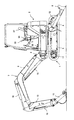
- FIG. 1 is a side view showing the structure of a hydraulic excavator in the present embodiment.
- the hydraulic excavator of the present embodiment includes a lower traveling body 1 capable of self-propelling and an upper revolving body 2 provided on the upper side of the lower traveling body 1 so as to be able to swivel. Constitutes the car body.
- the upper swing body 2 is rotated by a swing motor 13.
- the lower traveling body 1 includes an H-shaped track frame 3 as viewed from above.
- the track frame 3 is provided on the center frame extending in the left-right direction (perpendicular to the paper surface in FIG. 1) and on the left side of the center frame (front side toward the paper surface in FIG. 1).
- the left side frame extends in the middle left and right direction
- the right side frame is provided on the right side of the center frame (back side toward the paper surface in FIG. 1) and extends in the front-rear direction.
- the left crawler type traveling device 4 is provided on the left side frame and is driven by the left traveling motor 15.
- the right crawler type traveling device 5 (see FIG. 5 described later) is provided on the right side frame and is driven by a right traveling motor 17 (see FIG. 5 described later).
- the lower traveling body 1 travels when the left and right traveling devices 4 and 5 are driven.
- the blade 6 is provided so as to be driven in the vertical direction (vertical direction in FIG. 1) with respect to the center frame, and is driven in the vertical direction by the blade cylinder 12.
- the working device 7 is connected to the front side (left side in FIG. 1) of the upper swing body 2.
- the work device 7 includes a swing post 8 that is connected to the upper swing body 2 so as to be rotatable in the left-right direction, a boom 9 that is connected to the swing post 8 so as to be able to rotate in the vertical direction, and a boom 9 that is turned up and down.
- An arm 10 that is movably connected and a bucket 11 that is rotatably connected to the arm 10 in the vertical direction are provided.
- the swing post 8 is rotated in the left-right direction by a swing cylinder 14 (see FIG. 2 described later) to swing the boom 9 in the left-right direction.
- the boom 9, the arm 10, and the bucket 11 are rotated in the vertical direction by the boom cylinder 18, the arm cylinder 16, and the bucket cylinder 19, respectively.
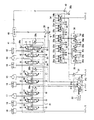
- FIG. 2 is a diagram illustrating a configuration of a hydraulic shovel drive device according to the present embodiment.
- the drive device includes hydraulic pumps P1, P2, and P3 that are main pumps driven by an engine 20 (prime mover), and a plurality of actuators that are operated by pressure oil discharged from the hydraulic pump P1 (in detail, The above-described right traveling motor 17, boom cylinder 18, and bucket cylinder 19) and a plurality of actuators (specifically, the above-described left traveling motor 15 and arm cylinder 16 described above) that are operated by pressure oil discharged from the hydraulic pump P2. ), A plurality of actuators (specifically, the blade cylinder 12, the swing motor 13, and the swing cylinder 14 described above) that are operated by pressure oil discharged from the hydraulic pump P3, and a valve unit 21.
- the hydraulic pumps P1 and P2 are constituted by split flow type hydraulic pumps.
- the valve unit 21 includes open center control valves 27, 28, and 29 for controlling the flow of pressure oil from the hydraulic pump P1 to the actuators 17, 18, and 19, respectively, and pressure oil from the hydraulic pump P2 to the actuators 15 and 16, respectively.
- Open center type control valves 25, 26 for controlling the flow of oil
- open center type control valves 22, 23, 24 for controlling the flow of pressure oil from the hydraulic pump P3 to the actuators 12, 13, 14 respectively.
- Main relief valves 30a, 30b and 30c for limiting the discharge pressures of the hydraulic pumps P1, P2 and P3, respectively.
- the drive device of the present embodiment includes a pilot pump P4 driven by the engine 20, a pilot relief valve 31 that keeps the discharge pressure of the pilot pump P4 constant, and operating devices 32 to 36 that operate the control valves 22 to 29.
- the operating device 33 is disposed on the left side of the driver's seat 37 (see FIG. 1) in the cab of the upper swing body 2, and the operating devices 32 and 34 are disposed on the right side of the driver's seat 37.
- the operation devices 35 and 36 are disposed on the front side of the driver seat 37.
- the operation device 32 for the boom and bucket has a cross operation type operation lever and pilot valves 32a to 32d that operate in accordance with the operation of the operation lever.
- the pilot valve 32a operates in response to the operation on the rear side of the operation lever, generates a boom raising pilot pressure a based on the discharge pressure of the pilot pump P4, and controls the boom raising pilot pressure a for the boom. It outputs to the one side pressure receiving part of the valve 28.
- the boom control valve 28 is switched to supply the pressure oil from the hydraulic pump P1 to the bottom side oil chamber of the boom cylinder 18, and the boom cylinder 18 is extended. As a result, the boom 9 is raised.
- the pilot valve 32b operates in accordance with the front side operation of the operation lever, generates a pilot pressure b for lowering the boom based on the discharge pressure of the pilot pump P4, and the pilot pressure b for lowering the boom is used as a boom control valve. 28 to the other pressure receiving part.
- the boom control valve 28 is switched to supply the pressure oil from the hydraulic pump P1 to the rod side oil chamber of the boom cylinder 18, and the boom cylinder 18 is shortened. As a result, the boom 9 is lowered.
- the pilot valve 32c operates in response to the left operation of the operation lever, generates a pilot pressure c for the bucket cloud based on the discharge pressure of the pilot pump P4, and uses the pilot pressure c for the bucket cloud as the bucket control valve. It outputs to 29 one side pressure receiving part. As a result, the bucket control valve 29 is switched, the pressure oil from the hydraulic pump P1 is supplied to the bottom side oil chamber of the bucket cylinder 19, and the bucket cylinder 19 is extended. As a result, the bucket 11 is clouded.
- the pilot valve 32d operates in response to the operation on the right side of the operation lever, generates a bucket dump pilot pressure d based on the discharge pressure of the pilot pump P4, and uses the bucket dump pilot pressure d as the bucket control valve. 29 to the other pressure receiving part.
- the bucket control valve 29 is switched to supply the pressure oil from the hydraulic pump P ⁇ b> 1 to the rod side oil chamber of the bucket cylinder 19, thereby shortening the bucket cylinder 19.
- the bucket 11 is dumped.
- the arm and turning operation device 33 has a cross operation type operation lever and pilot valves 33a to 33d that operate in accordance with the operation of the operation lever.
- the pilot valve 33a operates in response to the operation on the rear side of the operation lever, generates an arm pulling pilot pressure e based on the pressure of the pilot pump P4, and uses the arm pulling pilot pressure e as an arm control valve. 26 to one side pressure receiving portion.
- the arm control valve 26 is switched, pressure oil from the hydraulic pump P2 is supplied to the bottom side oil chamber of the arm cylinder 16, and the arm cylinder 16 is extended. As a result, the arm 10 is retracted.
- the pilot valve 33b operates according to the front side operation of the operation lever, generates a pilot pressure f for pushing the arm based on the pressure of the pilot pump P4, and uses the pilot pressure f for pushing the arm as the arm control valve 26. To the other pressure receiving part. As a result, the arm control valve 26 is switched to supply the pressure oil from the hydraulic pump P2 to the rod side oil chamber of the arm cylinder 16, and the arm cylinder 16 is shortened. As a result, the arm 10 is pushed.
- the pilot valve 33c operates in response to the left operation of the operation lever, generates a pilot pressure g for turning left based on the pressure of the pilot pump P4, and uses the pilot pressure g for turning left as a control valve 23 for turning. To one side pressure receiving part. As a result, the turning control valve 23 is switched, pressure oil from the hydraulic pump P3 is supplied to one side port of the turning motor 13, and the turning motor 13 is rotated in one direction. As a result, the upper swing body 2 is turned left.
- the pilot valve 33d operates in response to the right operation of the operation lever, generates a pilot pressure h for right turning based on the pressure of the pilot pump P4, and controls the pilot pressure h for right turning for turning. Output to the other pressure receiving portion of the valve 23.
- the turning control valve 23 is switched to supply the pressure oil from the hydraulic pump P3 to the opposite port of the turning motor 13, and the turning motor 13 is rotated in the opposite direction. As a result, the upper swing body 2 is turned right.
- the travel operation device 35 includes a left operation member (in detail, an operation lever and an operation pedal integrated) that can be operated in the front-rear direction, and a pilot valve that operates in accordance with the operation of the left operation member.
- the pilot valve 35a operates in accordance with the front side operation of the left operation member, generates a pilot pressure i for left travel based on the discharge pressure of the pilot pump P4, and uses the pilot pressure i for left travel for left travel. It outputs to the one side pressure receiving part of the control valve 25.
- the left travel control valve 25 is switched, pressure oil from the hydraulic pump P2 is supplied to the one side port of the left travel motor 15, and the left travel motor 15 is rotated in one direction.
- the left traveling device 4 is driven in one traveling direction (usually the forward direction).
- the pilot valve 35b operates in response to the rear operation of the left operating member, generates a pilot pressure j for left travel based on the discharge pressure of the pilot pump P4, and uses the left travel pilot pressure j for left travel. Output to the other pressure receiving portion of the control valve 25. As a result, the left travel control valve 25 is switched, pressure oil from the hydraulic pump P2 is supplied to the opposite port of the left travel motor 15, and the left travel motor 15 is rotated in the opposite direction. As a result, the left traveling device 4 is driven in the opposite traveling direction (usually the reverse direction).
- the pilot valve 35c operates according to the front side operation of the right operation member, generates a pilot pressure k for right travel based on the discharge pressure of the pilot pump P4, and uses the pilot pressure k for right travel for right travel. Output to one pressure receiving portion of the control valve 27. As a result, the right travel control valve 27 is switched, pressure oil from the hydraulic pump P1 is supplied to the one side port of the right travel motor 17, and the right travel motor 17 is rotated in one direction. As a result, the right traveling device 5 is driven in one traveling direction (usually the forward direction).
- the pilot valve 35d operates in response to the rear operation of the right operating member, generates a pilot pressure l for right traveling based on the discharge pressure of the pilot pump P4, and uses the pilot pressure l for right traveling to the right. Output to the other pressure receiving portion of the control valve 27.
- the right travel control valve 27 is switched to supply the pressure oil from the hydraulic pump P1 to the opposite port of the right travel motor 17, and the right travel motor 17 is rotated in the opposite direction.
- the right traveling device 5 is driven in the opposite traveling direction (usually the reverse direction).
- the operation device 36 for boom swing has an operation pedal that can be operated in the left-right direction, and pilot valves 36a and 36b that operate according to the operation of the operation pedal.
- the pilot valve 36a operates in response to the left operation of the operation pedal, generates a pilot pressure m for boom left swing based on the discharge pressure of the pilot pump P4, and uses the pilot pressure m for boom left swing as a boom swing. Is output to the one side pressure receiving portion of the control valve 24.
- the boom swing control valve 24 is switched to supply the pressure oil from the hydraulic pump P3 to the bottom oil chamber of the swing cylinder 14, and the swing cylinder 14 is extended.
- the boom 9 is swung to the left together with the swing post 8.
- the pilot valve 36b operates in response to the right operation of the operation pedal, generates a pilot pressure n for boom right swing based on the discharge pressure of the pilot pump P4, and uses the pilot pressure n for boom right swing as a boom swing. Output to the other pressure receiving portion of the control valve 24. As a result, the boom swing control valve 24 is switched to supply the pressure oil from the hydraulic pump P3 to the rod side oil chamber of the swing cylinder 14, and the swing cylinder 14 is shortened. As a result, the boom 9 is swung to the right together with the swing post 8.
- the drive device of the present embodiment is configured so that the blade 6 can be floated.
- the blade control valve 22 includes a neutral position I for stopping the blade 6, a raised position II for driving the blade 6 in the upward direction, and a lowered position for driving the blade 6 in the downward direction. In addition to III, it has a float position IV for making the blade 6 float. Then, by operating the blade operating device 34, the blade control valve 22 is switched from the neutral position I to any one of the raised position II, the lowered position III, and the float position IV.
- the blade operation device 34 has an operation lever that can be operated in the front-rear direction, and pilot valves 34a and 34b that operate in accordance with the operation of the operation lever.
- the pilot valve 34a operates according to the operation on the rear side from the neutral position of the operation lever, generates a pilot pressure o (corresponding to an increase command) based on the pressure of the pilot pump P4, and uses the pilot pressure o for the blade.
- the blade control valve 22 is switched from the neutral position I to the raised position II, the pressure oil from the hydraulic pump P3 is supplied to the rod side oil chamber of the blade cylinder 12, and the blade cylinder 12 is shortened. As a result, the blade 6 is raised.
- the pilot valve 34b operates according to the operation on the front side from the neutral position of the operation lever, and generates the pilot pressure p based on the pressure of the pilot pump P4. Specifically, as shown in FIG. 3, if the operating lever is in the neutral position (dead zone), that is, if the lever stroke s when operating the operating lever forward is less than a predetermined value s1, the pilot pressure p is set. If zero and the lever stroke s is the predetermined value s1, the pilot pressure p is set to the predetermined value p1. If the lever stroke s is not less than the predetermined value s1 and less than the reference value s2 (where s2> s1), the pilot pressure p is gradually increased as the lever stroke s is gradually increased. The pilot pressure p at this time is in the range of p2> p ⁇ p1, and corresponds to a lowering command.
- the pilot pressure p is rapidly increased to the maximum value pmax. .
- the pilot valve 34b outputs the pilot pressure p generated as described above to the other pressure receiving portion of the blade control valve 22 via the pilot oil passage 38b.
- the blade control valve 22 is switched from the neutral position I to the lowering position III, The pressure oil from the hydraulic pump P3 is supplied to the bottom side oil chamber of the blade cylinder 12, and the blade cylinder 12 is extended. As a result, the blade 6 is lowered.
- the opening area of the meter-in channel and the opening surface of the meter-out channel at the lowered position III of the blade control valve 22 are gradually increased.
- the blade control valve 22 When the pilot pressure p is the maximum value pmax (that is, when the pilot pressure p corresponds to a float command), the blade control valve 22 is switched to the float position IV, and the bottom side oil chamber and rod of the blade cylinder 12 are switched. The side oil chamber is communicated with the tank T. As a result, the blade 6 is brought into a floating state.
- an electromagnetic switching valve 39 provided in the pilot oil passage 38b and a controller 40 that controls the electromagnetic switching valve 39 are provided.
- the controller 40 includes an arithmetic control unit (for example, a CPU) that executes arithmetic processing and control processing based on a program, and a storage unit (for example, ROM, RAM) that stores the results of the program and arithmetic processing.
- the electromagnetic switching valve 39 can be switched between the communication position V and the cutoff position IV.
- the pilot pressure p can be output from the blade operating device 34 to the other pressure receiving portion of the blade control valve 22, and the pilot pressure p becomes effective.
- the electromagnetic switching valve 39 is in the cutoff position VI, the pilot pressure p cannot be output from the blade operating device 34 to the other pressure receiving portion of the blade control valve 22, and the pilot pressure p becomes invalid.
- a pressure sensor 41 that detects the pressure in the bottom oil chamber of the blade cylinder 12 is provided.
- the controller 40 stores a predetermined value (set value) that is set in advance as the pressure in the bottom side oil chamber of the blade cylinder 12 that serves as a reference for determining whether or not the blade 6 is jacking up the vehicle body. This is compared with the detection result.
- a pilot pressure sensor 42 is provided in the pilot oil passage 38b.
- the controller 40 includes a neutral pilot pressure (predetermined value) preset as a pilot pressure p that serves as a reference for determining whether or not the operation lever of the blade operation device 34 has been operated to the neutral position, and the operation lever of the blade operation device 34. Is stored as a pilot pressure p that is set in advance as a reference for determining whether or not the stroke is greater than or equal to the reference value s2, and is detected by the pilot pressure sensor 42. Compare them with the results.
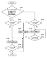
- FIG. 4 is a flowchart showing the processing procedure of the controller in the present embodiment.
- step S101 the controller 40 determines that the pressure in the bottom side oil chamber of the blade cylinder 12 is equal to or higher than a preset value (eg, 10 MPa), and the state is preset for a predetermined time (eg, several minutes). It is determined whether it has continued. If the pressure in the bottom oil chamber of the blade cylinder 12 is equal to or higher than the set value and this state continues for a predetermined time, it means that the blade 6 is jacking up the vehicle body.
- a preset value eg, 10 MPa
- a predetermined time eg, several minutes
- step S102 the controller 40 determines whether or not the pilot pressure p detected by the pilot pressure sensor 42 is greater than or equal to the determination value p2. If the pilot pressure p detected by the pilot pressure sensor 42 is greater than or equal to the determination value p2, it means that the operation lever of the blade operating device 34 is operated from the neutral position to the front side and the stroke s is greater than or equal to the reference value s2. To do.
- step S102 determines whether the pilot pressure p detected by the pilot pressure sensor 42 in step S102 is less than the determination value p2, in other words, if the lever stroke s is less than the reference value s2, the determination is NO, and step S103 Move on.
- the controller 40 turns off the control signal of the electromagnetic switching valve 39 and holds the electromagnetic switching valve 39 at the communication position V.
- the pilot pressure p corresponding to the lowering command is validated. Then, it returns to step S101 and performs the process mentioned above.
- step S104 the controller 40 turns on the control signal of the electromagnetic switching valve 39 and switches the electromagnetic switching valve 39 to the cutoff position VI. As a result, the pilot pressure p corresponding to the float command is invalidated.
- step S105 the controller 40 determines whether or not the pilot pressure p detected by the pilot pressure sensor 42 is less than a predetermined value p1. If the pilot pressure p detected by the pilot pressure sensor 42 is less than the predetermined value p1, it means that the operating lever of the blade operating device 34 has been operated to the neutral position. For example, if the pilot pressure p detected by the pilot pressure sensor 42 in step S105 is not less than the predetermined value p1, in other words, if the operating lever of the blade operating device 34 is not returned to the neutral position, The determination is no and the process returns to step S104. That is, the controller 40 holds the electromagnetic switching valve 39 at the cutoff position VI. Accordingly, the float command and the lowering command are invalidated until the operation lever of the blade operation device 34 is returned to the neutral position.
- step S105 when the pilot pressure p detected by the pilot pressure sensor 42 in step S105 is less than the predetermined value p1, in other words, when the operation lever of the blade operation device 34 is returned to the neutral position, the determination is made. Becomes YES, and the process returns to step S101. Thereafter, since the operation lever of the blade operation device 34 has been returned to the neutral position, the process proceeds to step S103 via step S101 and step S102 (or step S106 described later). In step S103, the controller 40 switches the electromagnetic switching valve 39 to the communication position V.
- step S101 the pressure in the bottom side oil chamber of the blade cylinder 12 is less than the set value in step S101 or the pressure in the bottom side oil chamber of the blade cylinder 12 is greater than or equal to the set value
- the state does not continue for a predetermined time.
- the determination in step S101 is NO and the process proceeds to step S106.
- step S106 the controller 40 determines whether or not the pilot pressure p detected by the pilot pressure sensor 42 is equal to or greater than a predetermined value p2.
- step S106 determines whether the pilot pressure p detected by the pilot pressure sensor 42 in step S106 is less than the determination value p2, in other words, if the lever stroke s is less than the reference value s2, the determination is NO, and step S103 Move on.
- the controller 40 turns off the control signal of the electromagnetic switching valve 39 and holds the electromagnetic switching valve 39 at the communication position V.
- the pilot pressure p corresponding to the lowering command is validated. Then, it returns to step S101 and performs the process mentioned above.
- step S106 determines whether the pilot pressure p detected by the pilot pressure sensor 42 in step S106 is greater than or equal to the determination value p2, in other words, if the lever stroke s is greater than or equal to the reference value s2, the determination is YES and step S107.
- step S107 as in step 103, the controller 40 turns on the control signal of the electromagnetic switching valve 39 and holds the electromagnetic switching valve 39 at the communication position V. As a result, the pilot pressure p corresponding to the float command is validated.
- step S108 the controller 40 determines whether or not the pilot pressure p detected by the pilot pressure sensor 42 is equal to or higher than the predetermined value p1 and lower than the determination value p2. If the pilot pressure p detected by the pilot pressure sensor 42 is not less than the predetermined value p1 and less than the determination value p2, it means that the pilot pressure p has changed from the float command to the lowering command. For example, if the pilot pressure p detected by the pilot pressure sensor 42 in step S108 is greater than or equal to the determination value p2, in other words, if the pilot pressure p remains the float command, the determination is NO, and step S107 Return to. That is, the controller 40 holds the electromagnetic switching valve 39 at the communication position V.
- step S108 when the pilot pressure p detected by the pilot pressure sensor 42 in step S108 is not less than the predetermined value p1 and less than the determination value p2, in other words, when the pilot pressure p is changed from the float command to the lowering command.
- the determination is YES, and the process proceeds to step S104.
- step S104 the controller 40 turns on the control signal of the electromagnetic switching valve 39 and switches the electromagnetic switching valve 39 to the cutoff position VI. As a result, the pilot pressure p corresponding to the lowering command is invalidated.
- step S105 the controller 40 determines whether or not the pilot pressure p detected by the pilot pressure sensor 42 is less than a predetermined value p1. For example, if the pilot pressure p detected by the pilot pressure sensor 42 in step S105 is not less than the predetermined value p1, in other words, if the operating lever of the blade operating device 34 is not returned to the neutral position, The determination is no and the process returns to step S104. That is, the controller 40 holds the electromagnetic switching valve 39 at the cutoff position VI. Thus, the lowering command is invalidated until the operation lever of the blade operation device 34 is returned to the neutral position.
- step S105 when the pilot pressure p detected by the pilot pressure sensor 42 in step S105 is less than the predetermined value p1, in other words, when the operation lever of the blade operation device 34 is returned to the neutral position, the determination is made. Becomes YES, and the process returns to step S101. Thereafter, since the operation lever of the blade operation device 34 has been returned to the neutral position, the process proceeds to step S103 via step S101 and step S102 or S106. In step S103, the controller 40 switches the electromagnetic switching valve 39 to the communication position V.
- the blade 6 of the excavator is used, for example, when jacking up the vehicle body or performing leveling work in order to maintain or wash the underbody of the vehicle body.
- the controller 40 does not perform the step of FIG.
- the process proceeds to step S104 via S101 and S102, and the electromagnetic switching valve 39 is switched to the cutoff position VI.
- the pilot pressure p corresponding to the float command is invalidated, and the blade control valve 22 is returned to the neutral position I. Accordingly, the blade 6 is not floated.
- the controller 40 holds the electromagnetic switching valve 39 at the cutoff position VI.
- the bottom side oil chamber and the rod side oil chamber of the blade cylinder 12 are connected to the tank T.
- the blade 6 enters a float state.
- the blade 6 descends by its own weight and comes into contact with the ground.
- the operator operates the operating device 35 to move the hydraulic excavator forward or backward, the blade 6 is in a float state, so that even if the ground is undulated, it can follow the undulated shape. Therefore, a good leveling operation can be performed.
- step S104 the controller 40 proceeds to step S104 through step S108 of FIG. 4 described above, and switches the electromagnetic switching valve 39 to the cutoff position VI. .
- the pilot pressure p corresponding to the lowering command is invalidated, and the blade control valve 22 is returned to the neutral position I.
- the controller 40 holds the electromagnetic switching valve 39 at the cutoff position VI until the operation lever of the blade operating device 34 is returned to the neutral position.
- the blade operating device 34 is operated to the front side and the stroke s is equal to or greater than the reference value s2.
- the pilot pressure p corresponding to the float command is invalidated and the blade control valve 22 is returned to the neutral position. That is, the lowering of the vehicle body can be prevented without bringing the blade 6 into the float state.
- the electromagnetic switching valve 39 is switched to the cutoff position VI (That is, when the blade control valve 22 is returned to the neutral position I) and thereafter the stroke of the operation lever of the blade operation device 34 is less than the specified value s2, the operation lever is returned to the neutral position. Meanwhile, the electromagnetic switching valve 39 is held at the cutoff position VI.
- the blade control valve 22 is moved from the neutral position I to the lowered position III (especially if the stroke of the operation lever is large, the opening area of the meter-in flow path and A sudden transition to a state where the meter-out opening area is large) can be prevented, and a sudden operation can be avoided.
- the electromagnetic switching valve 39 is held at the communication position V ( In other words, when the blade control valve 22 is switched to the float position IV) and then the stroke s of the operation lever of the blade operation device 34 is less than the specified value s2, the electromagnetic switching valve 39 is switched to the cutoff position VI. Further, thereafter, the electromagnetic switching valve 39 is held at the cutoff position VI until the operation lever returns to the neutral position.
- the blade control valve 22 is moved from the float position IV to the lowered position III (especially if the stroke of the operation lever is large, the opening area of the meter-in flow path and A sudden transition to a state where the meter-out opening area is large) can be prevented, and a sudden operation can be avoided.
- the pressure sensor 41 for detecting the pressure in the bottom oil chamber of the blade cylinder 12 is provided, and the pressure detected by the pressure sensor 41 is equal to or higher than a preset set value and is in that state.
- the controller 40 determines whether the blade 6 is jacking up the vehicle body based on whether or not it has continued for a predetermined time set in advance. Modifications are possible within the scope of the spirit and technical idea of the invention. That is, for example, a pressure sensor that detects the pressure of the rod side oil chamber of the blade cylinder 12 is provided, and the pressure detected by the pressure sensor is equal to or less than a preset value, and the state is set for a predetermined time.
- the controller may determine whether or not the blade 6 is jacking up the vehicle body depending on whether or not it has continued.
- a first pressure sensor that detects the pressure in the bottom side oil chamber of the blade cylinder 12 and a second pressure sensor that detects the pressure in the rod side oil chamber of the blade cylinder 12 are provided and detected by the first pressure sensor.
- the pressure detected by the second pressure sensor is less than or equal to a preset second set value (where the second set value is less than the first set value).
- the controller may determine whether or not the blade 6 is jacking up the vehicle body. Also in these modified examples, the same effect as the one embodiment can be obtained.
- the blade operation device 34 generates a pilot pressure according to the stroke of the operation lever and outputs it to the blade control valve 22 as an example.
- the present invention is not limited to this. Modifications can be made without departing from the spirit and technical idea of the present invention. That is, the blade operating device 34 detects the stroke of the operating lever and outputs it to the controller. The controller generates a control signal according to the stroke of the operating lever and outputs it to the electromagnetic proportional pressure reducing valve. A configuration may be adopted in which pilot pressure is generated according to the signal and output to the blade control valve.
- the controller may switch between enabling and disabling the float command and the lowering command by performing processing for enabling or disabling the control signal. Also in such a modification, the same effect as the one embodiment can be obtained.
- control valves 22 to 29 are open center type, and the pressure oil from the hydraulic pumps P1, P2, P3 is returned to the tank when they are in the neutral position (
- an open center system has been described as an example, the present invention is not limited to this, and modifications can be made without departing from the spirit and technical idea of the present invention. That is, the control valve is a closed center type, and when they are in the neutral position, the pressure oil from the hydraulic pump is returned to the tank via the unload valve (closed center with a load sensing control function). System).
- the present invention is not limited thereto, and the present invention may be applied to other construction machines (specifically, for example, a wheel loader). .
Landscapes
- Engineering & Computer Science (AREA)
- Mining & Mineral Resources (AREA)
- Civil Engineering (AREA)
- General Engineering & Computer Science (AREA)
- Structural Engineering (AREA)
- Mechanical Engineering (AREA)
- Physics & Mathematics (AREA)
- Fluid Mechanics (AREA)
- Life Sciences & Earth Sciences (AREA)
- General Life Sciences & Earth Sciences (AREA)
- Paleontology (AREA)
- Operation Control Of Excavators (AREA)
Priority Applications (3)
| Application Number | Priority Date | Filing Date | Title |
|---|---|---|---|
| CN201980004061.6A CN111051615B (zh) | 2018-02-09 | 2019-01-31 | 工程机械 |
| US16/641,712 US10995473B2 (en) | 2018-02-09 | 2019-01-31 | Construction machine |
| EP19750966.4A EP3660223B1 (de) | 2018-02-09 | 2019-01-31 | Baumaschinen |
Applications Claiming Priority (2)
| Application Number | Priority Date | Filing Date | Title |
|---|---|---|---|
| JP2018-022422 | 2018-02-09 | ||
| JP2018022422A JP6882214B2 (ja) | 2018-02-09 | 2018-02-09 | 建設機械 |
Publications (1)
| Publication Number | Publication Date |
|---|---|
| WO2019155984A1 true WO2019155984A1 (ja) | 2019-08-15 |
Family
ID=67549352
Family Applications (1)
| Application Number | Title | Priority Date | Filing Date |
|---|---|---|---|
| PCT/JP2019/003503 Ceased WO2019155984A1 (ja) | 2018-02-09 | 2019-01-31 | 建設機械 |
Country Status (5)
| Country | Link |
|---|---|
| US (1) | US10995473B2 (de) |
| EP (1) | EP3660223B1 (de) |
| JP (1) | JP6882214B2 (de) |
| CN (1) | CN111051615B (de) |
| WO (1) | WO2019155984A1 (de) |
Families Citing this family (4)
| Publication number | Priority date | Publication date | Assignee | Title |
|---|---|---|---|---|
| CN108934171B (zh) * | 2017-03-24 | 2020-10-09 | 株式会社日立建机Tierra | 工程机械的液压驱动装置 |
| GB2593488B (en) * | 2020-03-24 | 2024-05-22 | Bamford Excavators Ltd | Hydraulic system |
| US12606985B2 (en) | 2023-08-02 | 2026-04-21 | Deere & Company | Collision avoidance system for avoiding collision between movable components and portions of a work machine |
| EP4549669A1 (de) * | 2023-11-06 | 2025-05-07 | Yanmar Holdings Co., Ltd. | Verfahren zur steuerung einer arbeitsmaschine und arbeitsmaschine |
Citations (6)
| Publication number | Priority date | Publication date | Assignee | Title |
|---|---|---|---|---|
| JPH06280287A (ja) * | 1993-03-29 | 1994-10-04 | Komatsu Mec Corp | ホイール式建設車両の走行振動抑制装置 |
| JP2002088796A (ja) | 2000-09-19 | 2002-03-27 | Kobelco Contstruction Machinery Ltd | ドーザ装置 |
| JP2004019807A (ja) * | 2002-06-17 | 2004-01-22 | Hitachi Constr Mach Co Ltd | 作業車両の走行制御装置 |
| JP2005207197A (ja) * | 2004-01-26 | 2005-08-04 | Shin Caterpillar Mitsubishi Ltd | 作業機械 |
| JP2010084333A (ja) * | 2008-09-29 | 2010-04-15 | Kubota Corp | 作業機のフロート制御システム |
| US20170211597A1 (en) * | 2014-04-04 | 2017-07-27 | Volvo Construction Equipment Ab | Hydraulic system and method for controlling an implement of a working machine |
Family Cites Families (6)
| Publication number | Priority date | Publication date | Assignee | Title |
|---|---|---|---|---|
| US4166506A (en) * | 1975-06-30 | 1979-09-04 | Kabushiki Kaisha Komatsu Seisakusho | Controlling apparatus for bulldozer blade |
| CN1008391B (zh) * | 1985-05-03 | 1990-06-13 | 维克斯公司 | 动力传动装置 |
| JPH11336116A (ja) * | 1998-05-29 | 1999-12-07 | Sumitomo Constr Mach Co Ltd | 建設機械の作業腕の油圧回路 |
| JP2009068173A (ja) * | 2007-09-10 | 2009-04-02 | Hitachi Constr Mach Co Ltd | 油圧ショベルの油圧システム |
| CN102265041B (zh) * | 2008-12-24 | 2014-02-12 | 斗山英维高株式会社 | 工程机械的液压泵控制装置 |
| WO2014208795A1 (ko) * | 2013-06-28 | 2014-12-31 | 볼보 컨스트럭션 이큅먼트 에이비 | 플로팅기능을 갖는 건설기계용 유압회로 및 플로팅기능 제어방법 |
-
2018
- 2018-02-09 JP JP2018022422A patent/JP6882214B2/ja active Active
-
2019
- 2019-01-31 CN CN201980004061.6A patent/CN111051615B/zh active Active
- 2019-01-31 US US16/641,712 patent/US10995473B2/en active Active
- 2019-01-31 WO PCT/JP2019/003503 patent/WO2019155984A1/ja not_active Ceased
- 2019-01-31 EP EP19750966.4A patent/EP3660223B1/de active Active
Patent Citations (6)
| Publication number | Priority date | Publication date | Assignee | Title |
|---|---|---|---|---|
| JPH06280287A (ja) * | 1993-03-29 | 1994-10-04 | Komatsu Mec Corp | ホイール式建設車両の走行振動抑制装置 |
| JP2002088796A (ja) | 2000-09-19 | 2002-03-27 | Kobelco Contstruction Machinery Ltd | ドーザ装置 |
| JP2004019807A (ja) * | 2002-06-17 | 2004-01-22 | Hitachi Constr Mach Co Ltd | 作業車両の走行制御装置 |
| JP2005207197A (ja) * | 2004-01-26 | 2005-08-04 | Shin Caterpillar Mitsubishi Ltd | 作業機械 |
| JP2010084333A (ja) * | 2008-09-29 | 2010-04-15 | Kubota Corp | 作業機のフロート制御システム |
| US20170211597A1 (en) * | 2014-04-04 | 2017-07-27 | Volvo Construction Equipment Ab | Hydraulic system and method for controlling an implement of a working machine |
Non-Patent Citations (1)
| Title |
|---|
| See also references of EP3660223A4 |
Also Published As
| Publication number | Publication date |
|---|---|
| EP3660223B1 (de) | 2022-11-16 |
| EP3660223A1 (de) | 2020-06-03 |
| US20200232180A1 (en) | 2020-07-23 |
| JP6882214B2 (ja) | 2021-06-02 |
| EP3660223A4 (de) | 2021-04-07 |
| CN111051615A (zh) | 2020-04-21 |
| US10995473B2 (en) | 2021-05-04 |
| CN111051615B (zh) | 2021-09-14 |
| JP2019138056A (ja) | 2019-08-22 |
Similar Documents
| Publication | Publication Date | Title |
|---|---|---|
| JP6687992B2 (ja) | 建設機械 | |
| EP2543777B1 (de) | Dämpferbetriebssteuerungsvorrichtung für ein nutzfahrzeug und dämpferbetriebssteuerungsverfahren | |
| JP6560831B2 (ja) | 建設機械の油圧駆動装置 | |
| WO2011061988A1 (ja) | 建設機械の油圧駆動装置 | |
| WO2011046184A1 (ja) | 作業機械の油圧システム | |
| WO2019155984A1 (ja) | 建設機械 | |
| CN112513381A (zh) | 挖掘工程机械的液压驱动装置 | |
| JP2018115461A (ja) | 建設機械 | |
| JP2017172223A (ja) | 小型の油圧ショベル | |
| WO2017061220A1 (ja) | 建設機械 | |
| JP2017125353A (ja) | ホイールローダの荷役装置 | |
| JP2010084333A (ja) | 作業機のフロート制御システム | |
| JP5328279B2 (ja) | 作業機のフロート制御システム | |
| CN110462140B (zh) | 作业车辆以及作业车辆的控制方法 | |
| JP2682926B2 (ja) | バックホーの油圧制御装置 | |
| KR20260057094A (ko) | 건설 기계 | |
| WO2025206076A1 (ja) | 建設機械 | |
| JP2020143452A (ja) | 建設機械 | |
| JP2021031964A (ja) | 建設機械 | |
| JP2010084330A (ja) | 作業機のフロート制御システム | |
| WO2019066025A1 (ja) | 作業車両及び作業車両の制御方法 | |
| JP2010084331A (ja) | 作業機のフロート制御システム |
Legal Events
| Date | Code | Title | Description |
|---|---|---|---|
| 121 | Ep: the epo has been informed by wipo that ep was designated in this application |
Ref document number: 19750966 Country of ref document: EP Kind code of ref document: A1 |
|
| ENP | Entry into the national phase |
Ref document number: 2019750966 Country of ref document: EP Effective date: 20200224 |
|
| NENP | Non-entry into the national phase |
Ref country code: DE |