WO2019156100A1 - Élément d'isolation d'arbre à rouleaux de four de recuit continu et four de recuit continu - Google Patents
Élément d'isolation d'arbre à rouleaux de four de recuit continu et four de recuit continu Download PDFInfo
- Publication number
- WO2019156100A1 WO2019156100A1 PCT/JP2019/004141 JP2019004141W WO2019156100A1 WO 2019156100 A1 WO2019156100 A1 WO 2019156100A1 JP 2019004141 W JP2019004141 W JP 2019004141W WO 2019156100 A1 WO2019156100 A1 WO 2019156100A1
- Authority
- WO
- WIPO (PCT)
- Prior art keywords
- roll
- roll shaft
- continuous annealing
- annealing furnace
- fiber blanket
- Prior art date
- Legal status (The legal status is an assumption and is not a legal conclusion. Google has not performed a legal analysis and makes no representation as to the accuracy of the status listed.)
- Ceased
Links
Images


Classifications
-
- C—CHEMISTRY; METALLURGY
- C21—METALLURGY OF IRON
- C21D—MODIFYING THE PHYSICAL STRUCTURE OF FERROUS METALS; GENERAL DEVICES FOR HEAT TREATMENT OF FERROUS OR NON-FERROUS METALS OR ALLOYS; MAKING METAL MALLEABLE, e.g. BY DECARBURISATION OR TEMPERING
- C21D9/00—Heat treatment, e.g. annealing, hardening, quenching or tempering, adapted for particular articles; Furnaces therefor
- C21D9/52—Heat treatment, e.g. annealing, hardening, quenching or tempering, adapted for particular articles; Furnaces therefor for wires; for strips ; for rods of unlimited length
- C21D9/54—Furnaces for treating strips or wire
- C21D9/56—Continuous furnaces for strip or wire
- C21D9/562—Details
- C21D9/563—Rolls; Drums; Roll arrangements
-
- F—MECHANICAL ENGINEERING; LIGHTING; HEATING; WEAPONS; BLASTING
- F27—FURNACES; KILNS; OVENS; RETORTS
- F27B—FURNACES, KILNS, OVENS OR RETORTS IN GENERAL; OPEN SINTERING OR LIKE APPARATUS
- F27B9/00—Furnaces through which the charge is moved mechanically, e.g. of tunnel type; Similar furnaces in which the charge moves by gravity
- F27B9/30—Details, accessories or equipment specially adapted for furnaces of these types
- F27B9/32—Casings
-
- C—CHEMISTRY; METALLURGY
- C21—METALLURGY OF IRON
- C21D—MODIFYING THE PHYSICAL STRUCTURE OF FERROUS METALS; GENERAL DEVICES FOR HEAT TREATMENT OF FERROUS OR NON-FERROUS METALS OR ALLOYS; MAKING METAL MALLEABLE, e.g. BY DECARBURISATION OR TEMPERING
- C21D1/00—General methods or devices for heat treatment, e.g. annealing, hardening, quenching or tempering
- C21D1/26—Methods of annealing
-
- C—CHEMISTRY; METALLURGY
- C21—METALLURGY OF IRON
- C21D—MODIFYING THE PHYSICAL STRUCTURE OF FERROUS METALS; GENERAL DEVICES FOR HEAT TREATMENT OF FERROUS OR NON-FERROUS METALS OR ALLOYS; MAKING METAL MALLEABLE, e.g. BY DECARBURISATION OR TEMPERING
- C21D9/00—Heat treatment, e.g. annealing, hardening, quenching or tempering, adapted for particular articles; Furnaces therefor
- C21D9/40—Heat treatment, e.g. annealing, hardening, quenching or tempering, adapted for particular articles; Furnaces therefor for rings; for bearing races
-
- C—CHEMISTRY; METALLURGY
- C21—METALLURGY OF IRON
- C21D—MODIFYING THE PHYSICAL STRUCTURE OF FERROUS METALS; GENERAL DEVICES FOR HEAT TREATMENT OF FERROUS OR NON-FERROUS METALS OR ALLOYS; MAKING METAL MALLEABLE, e.g. BY DECARBURISATION OR TEMPERING
- C21D9/00—Heat treatment, e.g. annealing, hardening, quenching or tempering, adapted for particular articles; Furnaces therefor
- C21D9/52—Heat treatment, e.g. annealing, hardening, quenching or tempering, adapted for particular articles; Furnaces therefor for wires; for strips ; for rods of unlimited length
- C21D9/54—Furnaces for treating strips or wire
- C21D9/56—Continuous furnaces for strip or wire
-
- F—MECHANICAL ENGINEERING; LIGHTING; HEATING; WEAPONS; BLASTING
- F16—ENGINEERING ELEMENTS AND UNITS; GENERAL MEASURES FOR PRODUCING AND MAINTAINING EFFECTIVE FUNCTIONING OF MACHINES OR INSTALLATIONS; THERMAL INSULATION IN GENERAL
- F16C—SHAFTS; FLEXIBLE SHAFTS; ELEMENTS OR CRANKSHAFT MECHANISMS; ROTARY BODIES OTHER THAN GEARING ELEMENTS; BEARINGS
- F16C13/00—Rolls, drums, discs, or the like; Bearings or mountings therefor
- F16C13/02—Bearings
-
- F—MECHANICAL ENGINEERING; LIGHTING; HEATING; WEAPONS; BLASTING
- F27—FURNACES; KILNS; OVENS; RETORTS
- F27B—FURNACES, KILNS, OVENS OR RETORTS IN GENERAL; OPEN SINTERING OR LIKE APPARATUS
- F27B9/00—Furnaces through which the charge is moved mechanically, e.g. of tunnel type; Similar furnaces in which the charge moves by gravity
- F27B9/30—Details, accessories or equipment specially adapted for furnaces of these types
-
- F—MECHANICAL ENGINEERING; LIGHTING; HEATING; WEAPONS; BLASTING
- F27—FURNACES; KILNS; OVENS; RETORTS
- F27D—DETAILS OR ACCESSORIES OF FURNACES, KILNS, OVENS OR RETORTS, IN SO FAR AS THEY ARE OF KINDS OCCURRING IN MORE THAN ONE KIND OF FURNACE
- F27D7/00—Forming, maintaining or circulating atmospheres in heating chambers
- F27D7/06—Forming or maintaining special atmospheres or vacuum within heating chambers
Definitions
- the present invention relates to a heat insulating member for a roll shaft of a continuous annealing furnace, and more particularly, a lubricant that transfers heat to a bearing and / or leaks from a roll bearing between a roll shaft on the end side of the roll and a roll insertion hole. It is related with the roll axis
- the continuous annealing furnace is a furnace that sequentially receives coiled steel sheets inside a reducing atmosphere furnace and conveys them by a conveying roll (hearth roll) while continuously annealing.
- a conveying roll herein, both ends in the longitudinal direction (roll axis center direction) of the roll for conveying the steel sheet extend to the outside of the furnace through roll insertion holes provided in the furnace wall, and are supported rotatably by bearings.
- bearings Has been.
- a cylindrical member for preventing the outflow of the gas in the furnace is provided so as to surround the end of the roll. Lubricant such as grease is supplied to the bearing.
- Ceramic fibers having excellent characteristics as a lightweight refractory material and a heat insulating material have been used for lining in a furnace such as a continuous annealing treatment facility (for example, Patent Document 2).
- the ceramic fiber is produced by fiberizing a ceramic material in a high-temperature molten state by a spinning method using centrifugal force or a blowing method in which the ceramic fiber is blown off with high-speed compressed air.
- This ceramic fiber contains non-fibrous particles that remain in the form of particles that cannot be made into fibers, that is, shots, which cause dust.
- Patent Document 1 describes that a sealing disk is provided in order to prevent in-furnace gas from entering the bearing, but details of constituent materials of the sealing disk are not described.
- the present invention relates to heat insulation of a roll shaft for preventing heat of a hot gas in a furnace of a continuous annealing furnace from being transmitted to a bearing and / or lubricant leaking from a roll bearing from reaching the furnace along the roll shaft. It aims at providing a member and the continuous annealing furnace provided with this roll axial part heat insulation member.
- the gist of the present invention is as follows.
- a roll shaft heat insulating member installed between a roll insertion hole of a continuous annealing furnace and a roll bearing, It has an inorganic fiber blanket that is in contact with or close to the outer peripheral surface of the roll and has a shot content of 45 ⁇ m or more of 3% or less, and the residual thickness of the inorganic fiber blanket after a 1000 ° C. cycle test is 70% or more.
- a heat insulating member for a roll shaft part of a continuous annealing furnace characterized by
- the roll shaft heat insulating member has a casing having a drum portion surrounding the outer peripheral surface of the roll coupled with the furnace wall or the roll bearing support member, and the inorganic fiber blanket is included in the drum portion of the casing.
- the roll shaft heat insulating member of the continuous annealing furnace according to any one of [1] to [4], which is held along the peripheral surface.
- the inorganic fiber blanket has a plate shape, and a plurality of inorganic fiber blankets are arranged in a circumferential direction along the inner peripheral surface of the drum portion, with each plate surface parallel to the axial direction of the drum portion.
- a roll shaft heat insulating member having an inorganic fiber blanket having a shot content of 45 ⁇ m or more of 3% or less and a residual thickness after a cycle test at 1000 ° C. of 70% or more is installed between the roll insertion hole and the roll. By doing so, it is possible to prevent heat from entering the furnace. As a result, the temperature rise of the bearing is suppressed, and soot generation due to grease carbonization is prevented. Thereby, surface defects such as non-plating can be prevented, and the frequency of the in-furnace cleaning operation for removing accumulated soot can be reduced.
- an inorganic fiber blanket having a shot content of 45 ⁇ m or more is 3% or less is used as a material for the roll shaft heat insulating member, particulate foreign matters derived from the inorganic fiber blanket are not mixed in the furnace, and the steel sheet and the roll It is preferable in that it does not cause scratches due to foreign matter, and it is not damaged when the roll shaft is rotated while the roll shaft is in contact with the roll shaft heat shield member. preferable.
- an inorganic fiber blanket with a residual thickness of 70% or more after a cycle test at 1000 ° C. the dimensions are less likely to change with respect to the movement of the roll such as the axial blurring of the roll under high temperature conditions. It is preferable in that a gap is not easily generated.
- soot when soot enters the furnace, the energy for warming the steel is originally taken away by the soot, but by preventing the soot from entering, it is possible to prevent a decrease in heating efficiency.
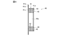
- FIG. 5 is a partially enlarged view of FIG. 4. It is a front view of the roll axis
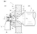
- FIG. 1 shows a longitudinal sectional view of the vicinity of a roll shaft portion of a continuous annealing furnace 1 according to the first embodiment.
- the continuous annealing furnace 1 is provided with a large number of horizontally arranged rolls 2 for conveying the steel plate to be treated.
- the roll 2 has an equal diameter large diameter portion 2a and roll shaft portions 2b on both ends of the large diameter portion 2a.
- the roll shaft portion 2b has a tapered portion 2c whose diameter gradually decreases from the large-diameter portion 2a toward both ends, and equal-diameter portions 2d, 2e, and 2f on both ends of the tapered portion.
- the diameters of the equal diameter portions 2d, 2e, and 2f are reduced in this order.
- the equal diameter portion 2 f is supported by the roll support member 4 through the bearing 3.
- Grease is supplied to the bearing 3 via an injection pipe (not shown).
- the roll support member 4 has a first plate 4a facing the furnace body 1, a second plate 4b perpendicular to the first plate 4a, and a bearing holding housing 4c.
- a roll insertion port 4d is provided in the first plate.
- the furnace body side wall 10 of the continuous annealing furnace 1 has an iron skin 11 and a ceramic fiber liner 12 provided inside the iron skin 11.
- a liner block 20 is attached to an opening 13 provided in the furnace body side wall 10.
- the liner block 20 includes an iron skin 21 and a ceramic fiber liner 22 provided inside the furnace of the iron skin 21.
- a roll insertion hole 23 is provided so as to penetrate the liner 22 and the iron skin 21.
- a seat plate 21 a made of an annular iron plate is fixed to the periphery of the roll insertion hole 23 on the iron skin 21.
- the roll insertion hole 23 has a tapered shape in which the inside of the furnace has a larger diameter toward the inside of the furnace, and the outside of the furnace is a cylindrical isometric hole.
- the roll shaft portion 2 b extends outside the furnace through the roll insertion hole 23.
- a cylindrical cover 30 is provided so as to surround a portion of the roll shaft portion 2b extending from the roll insertion hole 23 to the outside of the furnace.
- the cylindrical cover 30 has a bellows shape that can be expanded and contracted in the cylinder axial direction.
- a first flange 31 provided on one end side of the cylindrical cover 30 is attached to the first plate 4 a of the roll support member 4 with bolts, nuts, and the like.
- the 2nd flange 32 provided in the other end side of cover 30 is attached to seat plate 21a of iron skin 21 with a bolt and a nut.
- the flange portion 41b of the roll shaft heat insulating member 40 is sandwiched between the second flange 32 and the seat plate 21a.
- the roll shaft heat insulating member 40 includes a casing 41 and an inorganic fiber blanket 42 held by the casing 41 as shown in FIGS.
- the casing 41 includes a cylindrical drum portion 41a, a flange portion 41b that projects radially outward from one end of the drum portion 41a, and an inner portion that projects inward from one end of the drum portion 41a in the cylinder axis direction. It has a facing flange portion 41c and a presser ring 43 that is detachably attached to the other end of the drum portion 41a in the cylinder axis direction with a screw or the like.
- a bolt (not shown) is inserted into a bolt insertion hole 41d provided in the flange portion 41b.
- This bolt is also inserted into a bolt insertion hole (not shown) provided in the second flange 32 of the cylindrical cover 30 and the seat plate 21a of the iron skin 21, and a nut is screwed.
- the flange part 41b is clamped between the 2nd flange 32 and the seat board 21a, and the roll axial part heat insulation member 40 is fixed to the liner block 20.
- the inorganic fiber blanket 42 has a ring shape (ring shape).
- a plurality of inorganic fiber blankets 42 are overlapped coaxially and stitched together with an alumina fiber rope 47 to form an inorganic fiber blanket laminate 48.
- One end surface of the inorganic fiber blanket laminate 48 in the stacking direction is overlapped with the flange portion 41 c, and the outer peripheral edge of the other end surface is pressed by the pressing ring 43. Thereby, the inorganic fiber blanket laminate 48 is held in the casing 41.
- Each inorganic fiber blanket 42 is overlapped so that the inner peripheral surfaces 42a thereof are aligned coaxially, and the inorganic fiber blanket laminate 48 has a cylindrical inner hole 48a.
- An amorphous refractory such as mortar may be adhered between each inorganic fiber blanket 42 to form an amorphous refractory layer.
- the adhesive strength between the inorganic fiber blankets 42 is increased, and the inside of the furnace generated by the grease volatilized outside the furnace or outside the furnace It is preferable in that it prevents intrusion.
- FIG. By having a shielding layer between each inorganic fiber blanket 42, it is preferable at the point which prevents the penetration
- the roll shaft portion 2b is inserted into the inner hole 48a of the inorganic fiber blanket laminate 48.
- the inner peripheral surface of the inner hole 48a is elastically pressed against the outer peripheral surface of the roll shaft portion 2b (small diameter portion 2c in this embodiment).
- the roll shaft heat insulating member 40 prevents further intrusion into the furnace. Therefore, the production
- the drum portion 41a of the roll shaft heat insulating member 40 is disposed in the furnace direction with respect to the flange portion 41b. However, as shown in FIG. 2, the drum portion 41a is disposed in the furnace outward direction with respect to the flange portion 41b. May be.
- the roll shaft heat insulating member 40 may be attached to the first plate 4a of the roll support member 4 as shown in FIG.
- the plate surface of the inorganic fiber blanket 42 is perpendicular to the axis of the inner hole 48a, but the present invention is not limited to this.
- the plate surface of the inorganic fiber blanket 42 ′ may be parallel to the axis of the drum portion 41 a as in the roll shaft heat insulating member 40 ′ of FIGS.
- the inorganic fiber blanket 42 ' has a rectangular plate shape and is laminated in the circumferential direction of the inner peripheral surface of the drum portion 41a.
- Each inorganic fiber blanket 42 ′ is thicker on the outer peripheral side than on the inner peripheral side.
- the superposed inorganic fiber blanket 42 ′ is bound and integrated by an alumina fiber rope 47 to form a cylindrical inorganic fiber blanket laminate 48 ′.
- an inorganic fiber sheet 49 is wound around the outer periphery of the cylindrical inorganic fiber blanket laminate 48 ', and a tightening band 50 is wound around the outer periphery thereof. Both ends of the tightening band 50 are inserted into slots (long holes) of the tightening rod 51. By rotating the tightening rod 51 around the axis of the rod as indicated by the arrow R, both ends of the tightening band 50 are wound around the rod 51, and the inorganic fiber blanket laminate 48 ′ is tightened by the tightening band 50. Thereby, when the hearth roll is displaced by expansion / contraction, it can follow according to tightening, and the gap between the roll shaft and the roll shaft portion heat shielding member can be made as small as possible.
- the inorganic fiber sheet 49 is folded and overlapped on the outer peripheral side of the fastening band 50.
- This inorganic fiber blanket laminate 48 ′ is also held in the casing 41 as in the inorganic fiber blanket laminate 48 as shown in FIGS. As shown in FIG. 7, the tightening rod 51 is bridged between the flange portion 41 c of the casing 41 and the presser ring 43.
- the inner peripheral surface of the inner hole 48a of the inorganic fiber blanket laminates 48 and 48 ′ is in contact with the outer peripheral surface of the roll shaft portion 2b, but the inner peripheral surface of the inner hole 48a and the outer periphery of the roll shaft portion 2b.
- a slight clearance (preferably 10 mm or less, more preferably 5 mm or less, particularly preferably 3 mm or less) may be present between the surface and the surface.
- the inorganic fiber blanket is preferably an alumina fiber blanket.
- an alumina fiber blanket having a shot content of 45 ⁇ m or less suitable for use in the present invention of 3% or less and an inorganic fiber blanket having a residual thickness after a cycle test at 1000 ° C. of 70% or more will be described.
- the alumina fiber blanket preferably has a shot content of 45 ⁇ m or more of 3% or less, particularly 2% or less.
- the measurement of the shot content of 45 ⁇ m or more contained in the alumina fiber blanket is 45 ⁇ m of 325 mesh in accordance with the measurement of the shot content contained in the ceramic fiber blanket of JIS R3311 (sieve JIS Z 8801 nominal size 212 ⁇ m). Measure using a sieve.
- the alumina fiber blanket used in the present invention is preferably substantially free of fibers having a fiber diameter of 3 ⁇ m or less and subjected to needling treatment. In addition, it is preferable also from the point of a load resistance by using this needle blanket.
- substantially free of fibers having a fiber diameter of 3 ⁇ m or less means that the fibers having a fiber diameter of 3 ⁇ m or less is 0.1 wt% or less of the total fiber weight.
- the average fiber diameter of the alumina fibers constituting the alumina fiber blanket used in the present invention is preferably 5 to 7 ⁇ m. If the average fiber diameter of the alumina fiber is too large, the repulsive force and toughness of the blanket will be lost, and if it is too small, the amount of dust floating in the air will increase and the probability that fibers with a fiber diameter of 3 ⁇ m or less will be contained is high. Become.
- the alumina / silica composition ratio (wt%) of the alumina fibers constituting the alumina fiber blanket used in the present invention is preferably in the range of 65 to 98/35 to 2, more preferably 68 to 85/32 to 15.
- the range is more preferably 70 to 80/30 to 20, and particularly preferably 70 to 76/30 to 24.
- the mullite crystal ratio of the alumina fibers constituting the alumina fiber blanket used in the present invention is not particularly limited, but is usually 85% or less, It is preferably 75% or less, more preferably 60% or less, further preferably 30% or less, still more preferably 20% or less, and particularly preferably 10% or less.
- the mullite crystal ratio is measured as follows.
- the mullite crystal ratio is in the above range in terms of achieving both heat insulation, workability, and cushioning properties.
- An example of such an alumina fiber blanket is MAFUTEC (registered trademark) manufactured by Mitsubishi Chemical Corporation.
- the thickness of the alumina fiber blanket used in the present invention is preferably 6 to 25 mm, more preferably 7 to 13 mm.
- This alumina fiber blanket preferably has a shrinkage rate (measurement method conforms to JIS R3311) of less than 1% under the condition of heating at 5 ° C./min and holding at 1500 ° C. for 8 hours.
- the basis weight of the alumina fiber blanket used in the present invention is preferably 1000 to 3000 g / m 2 , more preferably 1200 to 2800 g / m 2 , and particularly preferably 1400 to 2500 g / m 2 .
- the inorganic fiber blanket such as an alumina fiber blanket has a residual thickness after a cycle test at 1000 ° C. in the measurement method described below of 70% or more, preferably 75% or more, more preferably 80%. It is more preferably 85% or more, particularly preferably 90% or more, particularly preferably 96% or more.
- Measurement method Samples obtained by cutting a plurality of inorganic blankets 10 mm long and 50 mm wide, arranged so that the cut end surfaces of the samples are exposed, the samples are sewn with alumina thread, and integrated samples (45 mm long x horizontal) 50 mm ⁇ height 10 mm). After the sample is compressed at a height of 8.25 mm for 30 minutes, the upper and lower plates are heated to 1000 ° C. and compressed from a height of 9.5 mm (open side) to a height of 7 mm (compression side). Repeat once. For the remaining thickness before and after the measurement, the ratio (%) of the inorganic fiber blanket thickness after measurement to the inorganic fiber blanket thickness before measurement is calculated.
- the repulsive force of the inorganic fiber blanket is maintained even when vibrations generated during operation of the furnace are applied, and the inner peripheral surface of the inner hole 48a of the inorganic fiber blanket laminates 48 and 48 ′ No gap is generated between the outer peripheral surfaces of the roll shaft portion, and the outflow of the gas in the furnace is sufficiently prevented.
- an alumina fiber needle blanket is preferable, and it is preferable in that the alumina fiber blanket is hardly peeled off.
- the needle mark density in the alumina fiber needle blanket used in the present invention that is, the number of needle marks per unit area (1 cm 2 ) of the mat surface is 1.0 to 50.0 / cm 2 as an average value of the entire mat surface, preferably Is 15.0 to 40.0 / cm 2 , particularly preferably 20.0 to 35.0 / cm 2 .
- the needle trace is calculated by cutting a 50 ⁇ 50 mm square into a sample, applying visible light from one side of the sample, and plotting with a magic pen behind the needle trace projected on the other side. The number of these points is counted to calculate the needle mark density.
- the inorganic fiber blanket such as an alumina fiber blanket used in the present invention preferably has a maximum load of 5.0 kgf or more under the following measurement conditions, more preferably 6.5 kgf or more, still more preferably 8.0 kgf or more, Particularly preferred is 8.5 kgf or more.
- the maximum load of the inorganic fiber blanket is in the above-described range, it is preferable in that it has durability against external force such as roll shaft blur, and as a result, a gap between the roll and the roll shaft heat insulating member is less likely to occur.
- the inorganic fiber blanket such as an alumina fiber blanket used in the present invention preferably has a lubricant absorption height of 9.5 mm or less, more preferably 8.5 mm or less, particularly preferably 8. 0 mm or less. Since the lubricant absorption height of the inorganic fiber blanket is in the above range, the lubricant leaking from the roll bearing is gradually absorbed, which is preferable in that the lubricant entering the furnace can be reduced.
- the above embodiment is an example of the present invention, and the present invention may be other than the above.
- the measurement sample was pulverized in a mortar, and measured with an X-ray diffractometer (manufactured by RIGAKU) at a voltage sensitivity of 30 kv, a current sensitivity of 40 mA, and a rate of 4 ° / min. The height h was read.
- the mullite crystal ratio at this time is a value represented by the following formula.
Landscapes
- Engineering & Computer Science (AREA)
- Chemical & Material Sciences (AREA)
- Mechanical Engineering (AREA)
- General Engineering & Computer Science (AREA)
- Crystallography & Structural Chemistry (AREA)
- Thermal Sciences (AREA)
- Physics & Mathematics (AREA)
- Materials Engineering (AREA)
- Metallurgy (AREA)
- Organic Chemistry (AREA)
- Furnace Housings, Linings, Walls, And Ceilings (AREA)
- Heat Treatment Of Strip Materials And Filament Materials (AREA)
- Heat Treatments In General, Especially Conveying And Cooling (AREA)
- Furnace Details (AREA)
Abstract
Priority Applications (4)
| Application Number | Priority Date | Filing Date | Title |
|---|---|---|---|
| CN201980009427.9A CN111630191A (zh) | 2018-02-06 | 2019-02-06 | 连续退火炉的辊轴部隔热部件和连续退火炉 |
| JP2019570767A JP7205499B2 (ja) | 2018-02-06 | 2019-02-06 | 連続焼鈍炉のロール軸部断熱部材及び連続焼鈍炉 |
| KR1020207017288A KR102668002B1 (ko) | 2018-02-06 | 2019-02-06 | 연속 소둔로의 롤축부 단열 부재 및 연속 소둔로 |
| US16/944,232 US11536515B2 (en) | 2018-02-06 | 2020-07-31 | Roller shaft portion thermal insulation member for continuous annealing furnace and continuous annealing furnace |
Applications Claiming Priority (2)
| Application Number | Priority Date | Filing Date | Title |
|---|---|---|---|
| JP2018019476 | 2018-02-06 | ||
| JP2018-019476 | 2018-02-06 |
Related Child Applications (1)
| Application Number | Title | Priority Date | Filing Date |
|---|---|---|---|
| US16/944,232 Continuation US11536515B2 (en) | 2018-02-06 | 2020-07-31 | Roller shaft portion thermal insulation member for continuous annealing furnace and continuous annealing furnace |
Publications (1)
| Publication Number | Publication Date |
|---|---|
| WO2019156100A1 true WO2019156100A1 (fr) | 2019-08-15 |
Family
ID=67549398
Family Applications (1)
| Application Number | Title | Priority Date | Filing Date |
|---|---|---|---|
| PCT/JP2019/004141 Ceased WO2019156100A1 (fr) | 2018-02-06 | 2019-02-06 | Élément d'isolation d'arbre à rouleaux de four de recuit continu et four de recuit continu |
Country Status (5)
| Country | Link |
|---|---|
| US (1) | US11536515B2 (fr) |
| JP (1) | JP7205499B2 (fr) |
| KR (1) | KR102668002B1 (fr) |
| CN (1) | CN111630191A (fr) |
| WO (1) | WO2019156100A1 (fr) |
Cited By (1)
| Publication number | Priority date | Publication date | Assignee | Title |
|---|---|---|---|---|
| TWI711703B (zh) * | 2020-04-05 | 2020-12-01 | 協鋐機電有限公司 | 退火爐 |
Families Citing this family (1)
| Publication number | Priority date | Publication date | Assignee | Title |
|---|---|---|---|---|
| JP7413677B2 (ja) * | 2019-08-09 | 2024-01-16 | 株式会社リコー | 現像装置及びプロセスカートリッジ及び画像形成装置 |
Citations (6)
| Publication number | Priority date | Publication date | Assignee | Title |
|---|---|---|---|---|
| JPS5479547U (fr) * | 1977-11-16 | 1979-06-06 | ||
| JPH0211154U (fr) * | 1988-06-30 | 1990-01-24 | ||
| JP2006010107A (ja) * | 2004-06-22 | 2006-01-12 | Nippon Steel Corp | 炉内ライニング |
| JP2014020464A (ja) * | 2012-07-18 | 2014-02-03 | Jfe Steel Corp | 軸受装置および連続焼鈍炉 |
| CN104088910A (zh) * | 2014-07-15 | 2014-10-08 | 中冶南方(武汉)威仕工业炉有限公司 | 冷轧退火炉炉辊轴承用组合密封装置 |
| JP2016183784A (ja) * | 2015-03-25 | 2016-10-20 | 三菱樹脂株式会社 | 連続焼鈍炉用炉床及び連続焼鈍炉 |
Family Cites Families (14)
| Publication number | Priority date | Publication date | Assignee | Title |
|---|---|---|---|---|
| US5205398A (en) * | 1990-07-27 | 1993-04-27 | Eltech Systems Corporation | Insulating roll cover |
| DE4141250C2 (de) * | 1991-12-14 | 1993-10-14 | Loi Ind Ofenanlagen | Rolle für Rollenherdöfen und Verfahren zu ihrer Herstellung |
| US5355996A (en) * | 1993-08-02 | 1994-10-18 | Global Consulting, Inc. | Wear resistant ceramic fiber conveyor rolls |
| US5833455A (en) * | 1996-05-14 | 1998-11-10 | Bricmont, Inc. | Dry roll furnace arrangement |
| JP4144724B2 (ja) * | 1999-09-16 | 2008-09-03 | サンゴバン・ティーエム株式会社 | 無機繊維ブロック |
| JP2006170254A (ja) | 2004-12-13 | 2006-06-29 | Nisshin Steel Co Ltd | 焼鈍炉ロール軸受け構造 |
| JP2009115414A (ja) * | 2007-11-08 | 2009-05-28 | Shinnikka Thermal Ceramics Corp | 耐火断熱ライニング材用セラミックファイバーモジュールおよび加熱炉の耐火断熱ライニング施工方法 |
| KR101223675B1 (ko) * | 2009-11-27 | 2013-01-17 | 주식회사 케이씨씨 | 염용해성 세라믹 섬유 조성물 |
| KR101206365B1 (ko) * | 2010-02-24 | 2012-11-29 | 주식회사 케이씨씨 | 세라믹 섬유 제조용 조성물 및 그로부터 제조된 고온단열재용 생체용해성 세라믹 섬유 |
| JP5418300B2 (ja) * | 2010-02-26 | 2014-02-19 | 株式会社Ihi | 炉内搬送用ロール |
| CN202989214U (zh) * | 2012-12-14 | 2013-06-12 | 中冶南方(武汉)威仕工业炉有限公司 | 新型硅钢退火炉碳套辊密封块 |
| CN203513755U (zh) * | 2013-08-01 | 2014-04-02 | 宝钢德盛不锈钢有限公司 | 一种用于连续退火炉的圆盘辊 |
| CN104073604A (zh) * | 2014-07-15 | 2014-10-01 | 中冶南方(武汉)威仕工业炉有限公司 | 降低硅钢退火炉炉辊轴承温度装置 |
| CN204286101U (zh) * | 2014-11-07 | 2015-04-22 | 武汉钢铁(集团)公司 | 耐火纤维炉衬结构 |
-
2019
- 2019-02-06 CN CN201980009427.9A patent/CN111630191A/zh active Pending
- 2019-02-06 KR KR1020207017288A patent/KR102668002B1/ko active Active
- 2019-02-06 WO PCT/JP2019/004141 patent/WO2019156100A1/fr not_active Ceased
- 2019-02-06 JP JP2019570767A patent/JP7205499B2/ja active Active
-
2020
- 2020-07-31 US US16/944,232 patent/US11536515B2/en active Active
Patent Citations (6)
| Publication number | Priority date | Publication date | Assignee | Title |
|---|---|---|---|---|
| JPS5479547U (fr) * | 1977-11-16 | 1979-06-06 | ||
| JPH0211154U (fr) * | 1988-06-30 | 1990-01-24 | ||
| JP2006010107A (ja) * | 2004-06-22 | 2006-01-12 | Nippon Steel Corp | 炉内ライニング |
| JP2014020464A (ja) * | 2012-07-18 | 2014-02-03 | Jfe Steel Corp | 軸受装置および連続焼鈍炉 |
| CN104088910A (zh) * | 2014-07-15 | 2014-10-08 | 中冶南方(武汉)威仕工业炉有限公司 | 冷轧退火炉炉辊轴承用组合密封装置 |
| JP2016183784A (ja) * | 2015-03-25 | 2016-10-20 | 三菱樹脂株式会社 | 連続焼鈍炉用炉床及び連続焼鈍炉 |
Cited By (1)
| Publication number | Priority date | Publication date | Assignee | Title |
|---|---|---|---|---|
| TWI711703B (zh) * | 2020-04-05 | 2020-12-01 | 協鋐機電有限公司 | 退火爐 |
Also Published As
| Publication number | Publication date |
|---|---|
| CN111630191A (zh) | 2020-09-04 |
| JP7205499B2 (ja) | 2023-01-17 |
| JPWO2019156100A1 (ja) | 2021-03-18 |
| US20200363130A1 (en) | 2020-11-19 |
| US11536515B2 (en) | 2022-12-27 |
| KR102668002B1 (ko) | 2024-05-21 |
| KR20200116907A (ko) | 2020-10-13 |
Similar Documents
| Publication | Publication Date | Title |
|---|---|---|
| CN1131093C (zh) | 低温排气处理装置用的非晶形非膨胀无机纤维衬垫 | |
| US9751281B2 (en) | Inorganic fiber molded body and process for producing the same | |
| Bischoff et al. | Microstructural studies of the interfacial zone of a SiC‐fiber‐reinforced lithium aluminum silicate glass‐ceramic | |
| CN1469807A (zh) | 供防火屏障用的层压片料 | |
| US9452719B2 (en) | High temperature resistant insulation mat | |
| WO2019156100A1 (fr) | Élément d'isolation d'arbre à rouleaux de four de recuit continu et four de recuit continu | |
| CN105829607A (zh) | 无机纤维纸 | |
| KR101487036B1 (ko) | 시트 유리의 제조를 위한 인발롤 재료 | |
| JPS5858307B2 (ja) | デイスクロ−ル | |
| US20230357971A1 (en) | Melt-Formed Inorganic Fibres | |
| He et al. | Microstructural evolution of Hi-NicalonTM SiC fibers annealed and crept in various oxygen partial pressure atmospheres | |
| Gogotsi et al. | Oxidation and properties degradation of SiC fibres below 850 C | |
| JP2016183784A (ja) | 連続焼鈍炉用炉床及び連続焼鈍炉 | |
| TW200905021A (en) | Expandable graphite sheet, method for protecting carbonaceous crucible using the expandable graphite sheet, and single crystal pulling apparatus | |
| Kerr et al. | The cyclic fatigue of high-performance fibers | |
| JP4823763B2 (ja) | 熱処理炉及び熱処理炉用バーナーポート | |
| WO2017115400A1 (fr) | Joint spiralé | |
| US20240175210A1 (en) | Inorganic fiber sheet | |
| JP2016033279A (ja) | ピッチ系炭素繊維及びその製造方法 | |
| Ozcan et al. | The effect of heat treatment temperature on the interfacial shear strength of C/C composites | |
| KR102440269B1 (ko) | 생체용해성 섬유를 포함하는 고온로용 롤디스크 및 내화성형체 | |
| JP2002364985A (ja) | 炉内ライニング | |
| JPH05172133A (ja) | ディスクロール | |
| TW202248007A (zh) | 耐熱結構體及熱處理爐用構件 | |
| JP7024210B2 (ja) | 連続焼鈍炉の炉内ライニング及び連続焼鈍炉 |
Legal Events
| Date | Code | Title | Description |
|---|---|---|---|
| 121 | Ep: the epo has been informed by wipo that ep was designated in this application |
Ref document number: 19751643 Country of ref document: EP Kind code of ref document: A1 |
|
| ENP | Entry into the national phase |
Ref document number: 2019570767 Country of ref document: JP Kind code of ref document: A |
|
| ENP | Entry into the national phase |
Ref document number: 20207017288 Country of ref document: KR Kind code of ref document: A |
|
| NENP | Non-entry into the national phase |
Ref country code: DE |
|
| 122 | Ep: pct application non-entry in european phase |
Ref document number: 19751643 Country of ref document: EP Kind code of ref document: A1 |