WO2019156194A1 - Système de véhicule - Google Patents
Système de véhicule Download PDFInfo
- Publication number
- WO2019156194A1 WO2019156194A1 PCT/JP2019/004522 JP2019004522W WO2019156194A1 WO 2019156194 A1 WO2019156194 A1 WO 2019156194A1 JP 2019004522 W JP2019004522 W JP 2019004522W WO 2019156194 A1 WO2019156194 A1 WO 2019156194A1
- Authority
- WO
- WIPO (PCT)
- Prior art keywords
- vehicle
- magnetic
- tag
- information
- marker
- Prior art date
- Legal status (The legal status is an assumption and is not a legal conclusion. Google has not performed a legal analysis and makes no representation as to the accuracy of the status listed.)
- Ceased
Links
Images




Classifications
-
- B—PERFORMING OPERATIONS; TRANSPORTING
- B65—CONVEYING; PACKING; STORING; HANDLING THIN OR FILAMENTARY MATERIAL
- B65G—TRANSPORT OR STORAGE DEVICES, e.g. CONVEYORS FOR LOADING OR TIPPING, SHOP CONVEYOR SYSTEMS OR PNEUMATIC TUBE CONVEYORS
- B65G63/00—Transferring or trans-shipping at storage areas, railway yards or harbours or in opening mining cuts; Marshalling yard installations
-
- G—PHYSICS
- G05—CONTROLLING; REGULATING
- G05D—SYSTEMS FOR CONTROLLING OR REGULATING NON-ELECTRIC VARIABLES
- G05D1/00—Control of position, course, altitude or attitude of land, water, air or space vehicles, e.g. using automatic pilots
- G05D1/02—Control of position or course in two dimensions
Definitions
- the present invention relates to a vehicle system for a work vehicle that moves within a work area set in an airport or a harbor.
- GSE Gate Support Equipment
- a work vehicle for moving the container is operated (see, for example, Patent Document 1). Since many operations are required for the operation of these work vehicles, a technology for reducing the cost required for the operation of the work vehicles is strongly demanded.
- the present invention has been made in view of the above-mentioned conventional problems, and intends to provide a vehicle system suitable for management and control of a vehicle moving in a traveling area such as an airport or a port working area. It is.
- the present invention is a system for a vehicle that moves in a traveling area, A plurality of magnetic markers arranged in the traveling area; A plurality of wireless tags for outputting unique tag information to the outside by wireless communication; A vehicle including a detection unit for detecting the magnetic marker, and a tag reader unit for acquiring tag information output from the wireless tag externally; A position specifying unit that specifies the magnetic marker detected by the vehicle using the tag information acquired by the vehicle, and specifies the vehicle position in the travel area based on the position of the specified magnetic marker, It exists in the system for vehicles by which the said radio
- the wireless tag that outputs the unique tag information to the outside by wireless communication is provided at the same position so as to correspond to at least a part of the magnetic markers.
- the position of the vehicle in the travel area is specified by specifying the magnetic marker detected by the vehicle using the tag information.
- the wireless tag since the wireless tag is arranged at the same position as at least a part of the magnetic marker, the wireless tag can be reached at the same time as reaching the magnetic marker regardless of the approach direction of the vehicle with respect to the magnetic marker. Therefore, when the vehicle detects the magnetic marker, it can communicate with the wireless tag at the same timing with the detection time as a reference, and tag information can be acquired with high reliability.
- the vehicle system of the present invention is a system that can identify the position of the vehicle in the traveling area with high certainty, and is suitable for management and control of the vehicle moving in the traveling area.
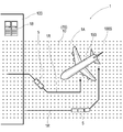
- FIG. 1 is an explanatory diagram of a vehicle system for a GSE vehicle according to a first embodiment.
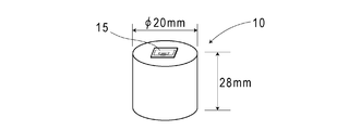
- 1 is a front view of an RFID tag in Embodiment 1.
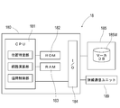
- FIG. 1 is a configuration diagram of a server device in Embodiment 1.
- FIG. 1 is a block diagram illustrating a system configuration of a work vehicle in Embodiment 1.
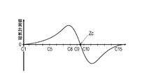
- FIG. The graph which illustrates the change of the magnetic measurement value at the time of passing the magnetic marker in Example 1.
- FIG. which illustrates distribution of the magnetic measurement value of the vehicle width direction at the time of passing the magnetic marker in Example 1.
- FIG. Explanatory drawing which shows the flow of operation
- Example 1 This example is an example related to a work vehicle system 1 that is an example of a vehicle system for managing a work vehicle 5 that moves in a work area 1A set in an airport or the like. The contents will be described with reference to FIGS.
- the work vehicle system 1 in FIG. 1 is a system for managing the work vehicle 5 that performs various operations related to the airplane 190 at an airport or the like.
- a work vehicle fuel vehicle
- a work vehicle talp vehicle
- a work vehicle belt loader, catering car
- a working vehicle towing tractor
- a work area 1 ⁇ / b> A that is a travel area of the work vehicle 5 is set across the parking space of the airplane 190 and the work space in the airport building 100.
- magnetic markers 10 are arranged in a lattice pattern at intervals of 2 m in length and width.
- the work vehicle 5 moves in the work area 1 ⁇ / b> A so as to travel along the magnetic marker 10 and performs work.
- the server device 18 and the work vehicle 5 are communicably connected via wireless communication.
- the server device 18 manages the vehicle position of each work vehicle 5, calculates the route 1R of each work vehicle 5, and remotely controls the work vehicle 5 so as to travel along the route 1R.
- the work vehicle 5 transmits the tag information acquired from the RFID tag (wireless tag) 15 to the server device 18 and automatically travels according to the control information received from the server device 18.
- the magnetic marker 10 (FIG. 2) has a columnar shape with a diameter of 20 mm and a height of 28 mm, and is laid in a state of being accommodated in a hole provided in the road surface 100S on which the work vehicle 5 moves. is there.
- the magnet constituting the magnetic marker 10 is a ferrite plastic magnet in which magnetic particles of iron oxide as a magnetic material are dispersed in a polymer material as a base material.
- the magnetic marker 10 has a magnetic flux density of 8 ⁇ T (micro Tesla) at an upper limit of 250 mm in the range of 100 to 250 mm assumed as a mounting height of the detection unit 2 (described later with reference to FIG. 5) in the work vehicle 5. Acts of magnetism.
- RFID (Radio Frequency IDentification) tags 15 that output tag information wirelessly are stacked on the surface (upper end surface) on the road surface 100S side.
- the RFID tag 15 operates by wireless external power feeding, and outputs a tag ID as an example of tag information to the outside.
- the RFID tag 15 is an electronic component in which an IC chip 157 is mounted on the surface of a tag sheet 150 cut out from, for example, a PET (Polyethylene terephthalate) film. On the surface of the tag sheet 150, print patterns of the loop coil 151 and the antenna 153 are provided.
- the loop coil 151 is a power receiving coil that generates an exciting current by electromagnetic induction from the outside.
- the antenna 153 is a transmission antenna for wirelessly transmitting position data and the like.
- the server device 18 includes an electronic board 180 on which electronic components such as a CPU (Central Processing Unit) 181, a ROM (Read Only Memory) 182, and a RAM (Random Access Memory) 183 are mounted. It is a computer device that is mainly configured.
- a storage device 185 such as a hard disk drive, a wireless communication unit 189, and the like are connected to the electronic board 180 via an I / O (Input / Output) 184.
- the server device 18 processes the software program read from the storage device 185 by the CPU 181 to realize the following functions as each unit.
- Position specifying unit A vehicle position that is the position of the work vehicle 5 is specified. The method of specifying the vehicle position differs between when the work vehicle 5 detects the magnetic marker 10 and between when the work marker 5 detects the magnetic marker 10 and until a new magnetic marker 10 is detected.
- the position specifying unit specifies the vehicle position using the tag information (tag) received by each work vehicle 5 from the RFID tag 15. Until the new magnetic marker 10 is detected, the position specifying unit specifies the vehicle position using the relative position of the destination estimated by the position estimation unit described next.
- Position estimation unit Estimates the relative position of the movement destination of the work vehicle 5 with reference to the laying position of the magnetic marker 10 which is an example of the position through which the work vehicle 5 has passed.
- Route calculation unit calculates a route (reference numeral 1R in FIG. 1) of the work vehicle 5 in accordance with preset work content.
- the work content including the waypoint and the destination is input by the work operator using an input device such as a keyboard, a mouse, or a display.
- Remote control unit Remotely controls the work vehicle 5 to move along the calculated route 1R.
- the remote control unit which is an example of a control unit, calculates control values such as a target steering angle and a target vehicle speed through arithmetic processing using various vehicle information such as the vehicle position and acceleration measurement value of each work vehicle 5 as input values. And return as control information.
- the target speed is zero, that is, a control value including stop control.
- a marker database (marker DB) 185 ⁇ / b> M that stores the laying position of each magnetic marker 10 arranged in the work area 1 ⁇ / b> A is formed using the storage area of the storage device 185.
- a tag ID (tag information) that is identification information of the attached RFID tag 15 is associated (associated) with the laying position of the magnetic marker 10 recorded in the marker DB 185M.
- the work vehicle 5 includes a detection unit 2 that detects the magnetic marker 10 and the RFID tag 15 in addition to a dedicated work device (not shown) according to the work purpose.
- a tag reader unit 34 for acquiring a tag ID, a control unit 32, and the like are provided as common equipment.
- the work vehicle 5 includes a vehicle ECU (Electronic Control Unit) 61 that controls a steering steering unit (not shown), an engine throttle, a brake actuator, and the like.
- the vehicle ECU 61 which is an example of a control unit, can execute control for automatically traveling the work vehicle 5 along the route 1 ⁇ / b> R (see FIG. 1) based on control information (control value) acquired from the server device 18.
- the detection unit 2 and the tag reader unit 34 are illustrated separately, but a unit in which these units are integrated may be employed.
- the detection unit 2 is a unit in which a sensor array 21 that is a magnetic detection unit and an IMU (Inertial Measurement Unit) 22 are integrated.
- This detection unit 2 is a rod-like unit that is long in the vehicle width direction, and is attached to the inside of the front bumper of the work vehicle 5 so as to face the road surface 100S, for example.
- the mounting height of the detection unit 2 with reference to the road surface 100S is 200 mm.
- the sensor array 21 of the detection unit 2 includes 15 magnetic sensors Cn (n is an integer of 1 to 15) arranged in a straight line along the vehicle width direction, a detection processing circuit 212 incorporating a CPU (not shown), and the like. It is equipped with. In the sensor array 21, 15 magnetic sensors Cn are arranged at equal intervals of 10 cm.
- the magnetic sensor Cn is a sensor that detects magnetism using a known MI effect (Magnet Impedance Effect) in which the impedance of a magnetic sensitive body such as an amorphous wire changes sensitively according to an external magnetic field.
- a magnetic sensitive body such as an amorphous wire is disposed along two orthogonal axes so that magnetism acting in the two orthogonal axes can be detected.
- the magnetic sensor Cn is incorporated in the sensor array 21 so that magnetic components in the traveling direction and the vehicle width direction can be detected.
- the magnetic sensor Cn is a highly sensitive sensor having a magnetic flux density measurement range of ⁇ 0.6 mT and a magnetic flux resolution within the measurement range of 0.02 ⁇ T.
- the magnetic marker 10 can act with magnetism having a magnetic flux density of 8 ⁇ T or more in the range of 100 to 250 mm assumed as the mounting height of the magnetic sensor Cn. If the magnetic marker 10 acts on magnetism having a magnetic flux density of 8 ⁇ T or more, it can be detected with high reliability using the magnetic sensor Cn having a magnetic flux resolution of 0.02 ⁇ T.
- the detection processing circuit 212 (FIG. 6) of the sensor array 21 is an arithmetic circuit that executes a marker detection process for detecting the magnetic marker 10.
- the detection processing circuit 212 is configured using a CPU that executes various calculations, a memory element such as a ROM or a RAM, and the like.
- the detection processing circuit 212 acquires the sensor signal output by each magnetic sensor Cn at a cycle of 3 kHz and executes marker detection processing. Then, the detection result of the marker detection process is input to the control unit 32. As will be described in detail later, in this marker detection process, in addition to the detection of the magnetic marker 10, the amount of lateral deviation of the work vehicle 5 with respect to the magnetic marker 10 is measured.
- the IMU 22 incorporated in the detection unit 2 is an inertial navigation unit that acquires measurement values necessary for estimating the relative position of the work vehicle 5 by inertial navigation.
- the IMU 22 includes a two-axis magnetic sensor 221 that is an electronic compass that measures azimuth, a two-axis acceleration sensor 222 that measures acceleration, and a two-axis gyro sensor 223 that measures angular velocity.
- the tag reader unit 34 in FIG. 6 is a communication unit that wirelessly communicates with the RFID tag 15 that is stacked on the surface (end surface) of the magnetic marker 10 (FIG. 2).
- the tag reader unit 34 wirelessly transmits power necessary for the operation of the RFID tag 15 to operate the RFID tag 15 and acquires a tag ID that is identification information of the RFID tag 15.
- the control unit 32 (FIG. 6) controls the detection unit 2 and the tag reader unit 34, and transmits and receives various information and data to and from the server device 18 (see FIG. 1). It is.
- the control unit 32 transmits vehicle information such as a tag ID acquired from the RFID tag 15 and a measured value by the IMU 22 to the server device 18, and acquires control information for automatic traveling from the server device 18.
- the control unit 32 inputs the acquired control information (control value) to the vehicle ECU 61.
- the vehicle information transmitted from the control unit 32 to the server device 18 is different between vehicle information transmitted every predetermined time during traveling and vehicle information transmitted when the magnetic marker 10 is detected.
- the vehicle information transmitted at any time while the work vehicle 5 is traveling includes the orientation measured by the biaxial magnetic sensor 221, the acceleration measured by the biaxial acceleration sensor 222, the measured value of the angular velocity measured by the biaxial gyro sensor 223, and the like. Is included.
- the vehicle information transmitted when the work vehicle 5 detects the magnetic marker 10 includes, in addition to these measured values, the fact that the magnetic marker 10 has been detected, the amount of lateral deviation with respect to the magnetic marker 10, and the tag ID acquired from the RFID tag 15. (Tag information).
- the marker detection process is a process executed by the sensor array 21 of the detection unit 2.
- the sensor array 21 performs a marker detection process with a period of 3 kHz using the magnetic sensor Cn.
- the magnetic sensor Cn is configured to measure the magnetic components in the traveling direction and the vehicle width direction of the work vehicle 5. For example, when the magnetic sensor Cn moves in the traveling direction and passes immediately above the magnetic marker 10, the magnetic measurement value in the traveling direction is reversed between positive and negative before and after the magnetic marker 10 as shown in FIG. It changes so as to cross zero at a position just above 10. Accordingly, when the work vehicle 5 is traveling, when the zero cross Zc in which the polarity of the traveling direction magnetism detected by any one of the magnetic sensors Cn is reversed occurs, the detection unit 2 is positioned immediately above the magnetic marker 10. I can judge. In this way, the detection processing circuit 212 determines that the magnetic marker 10 has been detected when the detection unit 2 is positioned directly above the magnetic marker 10 and the zero cross Zc of the magnetic measurement value in the traveling direction has occurred.
- the magnetic measurement value in the vehicle width direction is obtained from the magnetic marker 10.
- the sign is reversed on both sides of the sandwich, and changes so as to cross zero at a position directly above the magnetic marker 10.
- the sign of the magnetism in the vehicle width direction detected by the magnetic sensor Cn differs depending on which side the magnetic marker 10 is located.
- the two magnetic sensors Cn adjacent to each other with the zero cross Zc in which the polarity of the magnetism in the vehicle width direction is reversed are sandwiched.
- An intermediate position or a position immediately below the magnetic sensor Cn in which the detected magnetism in the vehicle width direction is zero and the signs of the outer magnetic sensors Cn are reversed is the position of the magnetic marker 10 in the vehicle width direction.
- the detection processing circuit 212 measures the deviation of the position of the magnetic marker 10 in the vehicle width direction with respect to the center position of the detection unit 2 (the position of the magnetic sensor C8) as the lateral shift amount. For example, in the case of FIG.
- the position of the zero cross Zc is a position corresponding to C9.5 in the middle of C9 and C10.
- the lateral deviation amount of the magnetic marker 10 is (9.5-8) ⁇ 10 cm with reference to C8 located at the center of the detection unit 2 in the vehicle width direction. It becomes.
- the server device 18 presents a work content input screen (not shown) for setting a predetermined work content on the work vehicle 5 to the work operator when performing remote control of the work vehicle 5.
- the server device 18 sets work contents such as a destination input by the work operator on the work content input screen using a keyboard, a mouse, or the like (S101). Then, a route for efficiently reaching the set destination is calculated using the vehicle position of the target work vehicle 5 as a start point (S102).
- the arrangement and laying position of each magnetic marker 10 arranged in the work area 1A are managed.
- the server device 18 determines a route through the magnetic marker 10 as a route for automatically traveling the work vehicle 5 (route 1R in FIG. 1), and starts remote control for automatically traveling the work vehicle 5 ( S103).
- control unit 32 of the work vehicle 5 tries to detect the magnetic marker 10 by causing the detection unit 2 to repeatedly execute the marker detection process P ⁇ b> 1 described above while automatically traveling by remote control by the server device 18.
- the magnetic marker 10 is detected, the above-described lateral shift amount with respect to the magnetic marker 10 measured by the detection unit 2 is acquired.
- the control unit 32 controls the tag reader unit 34 so that power can be supplied to the RFID tag 15 attached to the magnetic marker 10 (S202). .
- the control unit 32 operates the RFID tag 15 and acquires the tag ID wirelessly transmitted from the RFID tag 15 (S203). Then, the control unit 32 transmits the tag ID acquired together with the lateral deviation amount measured in the marker detection process P1 to the server device 18 (S204).
- the control unit 32 controls the IMU 22 to acquire measurement values such as acceleration, direction, and angular velocity (S205), and transmits these measurement values to the server device 18 (S206).
- the server device 18 determines whether or not the tag ID has been acquired from the work vehicle 5 (S104).
- the server device 18 obtains the tag ID (S104: YES)
- the server device 18 refers to the marker DB 185M, obtains the laying position (of the magnetic marker 10) to which the tag ID is linked, and specifies the vehicle position (S105).
- the vehicle position is specified by offsetting the laying position acquired with reference to the marker DB 185M by the amount of lateral deviation acquired together with the tag ID.
- the server device 18 starts from the work vehicle 5.
- the calculation which estimates a relative position using the vehicle information to acquire is performed (S115).
- the server device 18 calculates a displacement amount by second-order integration of acceleration, which is a measurement value of the 2-axis acceleration sensor 222 of the IMU 22 included in the work vehicle 5, and the work vehicle measured by the 2-axis gyro sensor 223 or the like.
- the relative position with respect to the reference position is estimated by integrating the amount of displacement along the direction of 5.
- a vehicle position specified based on the laying position of the latest magnetic marker 10 detected by the work vehicle 5 can be applied.
- the server device 18 identifies the vehicle position by adding the estimated relative position to the reference position (S105).
- the server device 18 routes the target work vehicle 5 by a calculation process using the vehicle position of the work vehicle 5 identified in step S105, the vehicle information acquired from the work vehicle 5 (measured values of the IMU 22), and the like as input values.
- a control value for traveling along 1R is calculated (S106).
- the server apparatus 18 transmits the control information containing the control value calculated by step S106 with respect to the work vehicle 5 of the transmission source of vehicle information.
- the control unit 32 of the work vehicle 5 inputs the control value transmitted as control information from the server device 18 to the vehicle ECU 61, and executes automatic traveling control (S207).
- the vehicle ECU 61 executes steering control, throttle control, and the like based on the control value input from the server device 18 to realize automatic travel of the work vehicle 5.
- the server device 18 repeatedly executes the processes of steps S104 to S106 until the work vehicle 5 reaches the destination that is the end point of the route 1R (S107: NO), and the work vehicle 5 is set according to the arrival at the destination. Remote control is terminated (S107: YES).
- the work vehicle system 1 configured as described above is a system that identifies the position of the work vehicle 5 using the tag ID of the RFID tag 15 disposed at the same position as the magnetic marker 10.
- the RFID tag 15 can transmit tag information by wireless communication, but it is difficult to specify the relative position with high accuracy on the vehicle side.
- the magnetic marker 10 can specify the relative position with high accuracy on the vehicle side.
- the RFID tag 15 that transmits the tag information and the magnetic marker 10 that can specify the relative position with high accuracy on the vehicle side can be combined well to specify the position of the work vehicle 5 with high accuracy. Realized.
- the magnetic marker 10 detected by the work vehicle 5 can be specified by attaching the RFID tag 15 to the magnetic marker 10.
- the marker DB 185M the laying position of each magnetic marker 10 is managed in a state where tag IDs are linked.
- the work vehicle 5 detects the magnetic marker 10
- the magnetic marker 10 can be identified and the laying position can be acquired.
- the vehicle position of the work vehicle 5 can be specified with high accuracy.
- the RFID tag 15 is attached near the center of the top surface of the magnetic marker 10. For this reason, the temporal relative relationship between the timing at which the magnetic marker 10 is detected and the timing at which communication with the RFID tag 15 becomes possible is almost constant, regardless of the direction in which the work vehicle 5 enters the magnetic marker 10. Therefore, when the work vehicle 5 detects the magnetic marker 10, it can communicate with the RFID tag 15 attached to the magnetic marker 10 with high reliability.
- the magnetic marker 10 serves as a mark, it is not necessary to search for the RFID tag 15 on the work vehicle 5 side and execute communication.
- this work vehicle system 1 since the range in which the radio waves of the tag reader unit 34 reach can be set narrow, interference with the RFID tag 15 attached to another adjacent magnetic marker 10 can be avoided.
- the magnetic markers 10 are arranged in a lattice pattern with a relatively narrow interval of 2 m, the effect of avoiding interference with the RFID tags 15 attached to other magnetic markers 10 is particularly effective. .
- the work vehicle system 1 is a system that can identify the position of the work vehicle 5 in the work area 1A with high reliability, and performs management, control, and the like of the work vehicle 5 that moves in the work area 1A with high reliability. it can.
- the work vehicle system 1 can specify the vehicle position of the work vehicle 5 without assuming reception of GPS radio waves or the like. Therefore, for example, in places where GPS radio waves become unstable, such as indoors or under airplanes, or in facilities such as airports where GPS accuracy can be intentionally suppressed, the accuracy of specifying the vehicle position is not affected. . If the vehicle position specified by the work vehicle system 1 is used, the position of the work vehicle 5 can be managed with high accuracy, and reliable remote control can be realized.
- the structure which attached the sheet-like RFID tag 15 to the upper surface of the magnetic marker 10 is illustrated, the structure in which the magnetic marker 10 and the RFID tag 15 are united is not essential. It is only necessary that the magnetic marker 10 and the RFID tag 15 be disposed at the same position, and the RFID tag 15 may be disposed directly above or below the magnetic marker 10 in the vertical direction.
- a configuration in which a work operator inputs work contents including a waypoint and a destination of the work vehicle 5 using an input device such as a keyboard, a mouse, a display, or the like is illustrated.
- the processing device that has input the aircraft take-off / departure information to determine necessary work by information processing using, for example, artificial intelligence, and to determine the work content of each work vehicle 5 according to the determined content.
- the RFID tag 15 may be attached to some of the magnetic markers 10.
- the laying position of the magnetic marker 10 can be acquired using the tag ID.
- the vehicle position of the work vehicle 5 may be speculatively specified by adding the relative position based on the measurement value by the IMU 22 using the laying position of the magnetic marker 10 as a reference position.
- the magnetic marker 10 without the RFID tag 15 is newly detected, the magnetic marker 10 may be specified by referring to the marker DB 185M and searching for the laying position closest to the estimated vehicle position. If the detected magnetic marker 10 can be specified, the vehicle position can be specified with high accuracy based on the laying position of the magnetic marker 10 as in the case where the tag ID can be acquired.
- the server device 18 has a remote control unit (control unit), and illustrates a configuration in which a plurality of work vehicles 5 are remotely controlled.
- each work vehicle 5 may include a control unit for moving the vehicle by automatic traveling. If the control unit is provided on the vehicle side, each work vehicle 5 acquires the configuration in which each work vehicle 5 autonomously travels autonomously while repeatedly specifying the vehicle position, and the vehicle position specified by the server device 18. A configuration that autonomously travels automatically based on the position can be employed.
- an inter-vehicle communication unit that performs inter-vehicle communication may be provided in each work vehicle 5. If other vehicle information including information indicating the absolute position or relative position of another vehicle can be acquired, each work vehicle 5 can move while avoiding a collision by exchanging information on each other's position. Further, for example, a distance measuring sensor such as a laser radar, a millimeter wave radar, or a sound wave radar may be employed as the other vehicle information acquisition unit. If a distance measuring sensor or the like is used, information representing a relative position with respect to another vehicle can be acquired as other vehicle information.
- a distance measuring sensor such as a laser radar, a millimeter wave radar, or a sound wave radar
- each work vehicle 5 can move more efficiently including the transfer of courses.
- each work vehicle 5 has a marker DB 185M. May be. If each work vehicle 5 includes the marker DB 185M, each work vehicle 5 can specify the vehicle position without depending on the information from the server device 18. In addition, if each work vehicle 5 includes the above-described control unit for automatic traveling, automatic traveling can be performed without depending on the control from the server device 18. As described above, each work vehicle 5 may transmit the vehicle position to the server device 18 even in a case where each work vehicle 5 is configured to be capable of autonomous automatic traveling. In this case, the server position of each work vehicle 5 can be managed on the server device 18 side. If the server device 18 manages the vehicle position of each work vehicle 5, for example, the setting of the movement route of each work vehicle 5 can be executed, and the work efficiency of the plurality of work vehicles 5 as a whole can be improved.
- the configuration for specifying the vehicle position of each work vehicle 5 in the work vehicle system 1 of this example is not only a system for automatically driving the work vehicle 5 by remote control or autonomous control, but also the work vehicle 5 driven by the operator. This is also useful for a system for managing the position with high accuracy on the server device side.
- the configuration of the work vehicle system 1 of this example is effective for management and control of the position of a vehicle that moves in a two-dimensional area with a high degree of freedom, such as a work vehicle used in a container yard of a port.
- tag ID which is the specific information of the RFID tag 15 is illustrated as tag information, but information indicating the laying position of the magnetic marker 10 or the like may be included in the tag information.
- the laying address in the lattice arrangement of the magnetic markers may be included in the tag information.
- a map database that stores map information including information such as the shape of the work area 1A, the arrangement of the magnetic markers, the position of the facility, and the parking place is preferably provided on the vehicle side.
Landscapes
- Engineering & Computer Science (AREA)
- Aviation & Aerospace Engineering (AREA)
- Radar, Positioning & Navigation (AREA)
- Remote Sensing (AREA)
- Physics & Mathematics (AREA)
- General Physics & Mathematics (AREA)
- Automation & Control Theory (AREA)
- Control Of Position, Course, Altitude, Or Attitude Of Moving Bodies (AREA)
Abstract
La présente invention concerne un système de véhicule de travail (1) pour des véhicules se déplaçant dans une zone de travail (1A) au niveau d'un aéroport, d'un port ou similaire, comprenant : un marqueur magnétique (10) qui est disposé dans une zone de travail (1A) ; une étiquette RFID (15) qui émet vers l'extérieur un identifiant d'étiquette à l'aide d'une communication sans fil ; un véhicule de travail (5) qui comprend une unité de détection pour détecter le marqueur magnétique (10), et une unité de lecture d'étiquette pour acquérir l'identifiant d'étiquette émis vers l'extérieur par l'étiquette RFID (15) ; et une unité de spécification de position qui spécifie la position du véhicule dans la zone de travail (1A) en identifiant le marqueur magnétique (10) détecté par le véhicule de travail (5) à l'aide de l'identifiant d'étiquette.
Applications Claiming Priority (2)
| Application Number | Priority Date | Filing Date | Title |
|---|---|---|---|
| JP2018-022655 | 2018-02-12 | ||
| JP2018022655A JP2019137521A (ja) | 2018-02-12 | 2018-02-12 | 車両用システム |
Publications (1)
| Publication Number | Publication Date |
|---|---|
| WO2019156194A1 true WO2019156194A1 (fr) | 2019-08-15 |
Family
ID=67549444
Family Applications (1)
| Application Number | Title | Priority Date | Filing Date |
|---|---|---|---|
| PCT/JP2019/004522 Ceased WO2019156194A1 (fr) | 2018-02-12 | 2019-02-07 | Système de véhicule |
Country Status (2)
| Country | Link |
|---|---|
| JP (1) | JP2019137521A (fr) |
| WO (1) | WO2019156194A1 (fr) |
Families Citing this family (7)
| Publication number | Priority date | Publication date | Assignee | Title |
|---|---|---|---|---|
| JP7453537B2 (ja) * | 2020-05-12 | 2024-03-21 | シンフォニアテクノロジー株式会社 | 走行経路設定システム及び走行経路設定方法 |
| JP7594175B2 (ja) * | 2020-11-06 | 2024-12-04 | シンフォニアテクノロジー株式会社 | 接近経路設定システム及び接近経路設定方法 |
| JP7587151B2 (ja) | 2021-04-01 | 2024-11-20 | 愛知製鋼株式会社 | 磁気マーカシステム、及び磁気マーカシステムの設計方法 |
| WO2022210194A1 (fr) * | 2021-04-01 | 2022-10-06 | 愛知製鋼株式会社 | Système |
| JP7628709B2 (ja) * | 2022-01-13 | 2025-02-12 | 高知県公立大学法人 | 全方向搬送システム |
| JP7815776B2 (ja) * | 2022-01-17 | 2026-02-18 | 株式会社豊田自動織機 | 位置特定装置 |
| JP7076935B1 (ja) | 2022-01-18 | 2022-05-30 | トーヨーカネツ株式会社 | 無人移送車走行用床装置 |
Citations (6)
| Publication number | Priority date | Publication date | Assignee | Title |
|---|---|---|---|---|
| JPH09245298A (ja) * | 1996-03-13 | 1997-09-19 | Toyota Motor Corp | 車両用自動走行装置 |
| JP2016170580A (ja) * | 2015-03-12 | 2016-09-23 | 株式会社シンテックホズミ | 搬送車システム |
| JP2017107456A (ja) * | 2015-12-10 | 2017-06-15 | 国立大学法人豊橋技術科学大学 | 自律走行ロボットシステム |
| WO2017187881A1 (fr) * | 2016-04-28 | 2017-11-02 | 愛知製鋼株式会社 | Système d'aide à la conduite |
| WO2017187879A1 (fr) * | 2016-04-28 | 2017-11-02 | 愛知製鋼株式会社 | Marqueur magnétique et système d'aide à la conduite |
| WO2017217423A1 (fr) * | 2016-06-17 | 2017-12-21 | 愛知製鋼株式会社 | Marqueur magnétique et système de marqueur |
-
2018
- 2018-02-12 JP JP2018022655A patent/JP2019137521A/ja active Pending
-
2019
- 2019-02-07 WO PCT/JP2019/004522 patent/WO2019156194A1/fr not_active Ceased
Patent Citations (6)
| Publication number | Priority date | Publication date | Assignee | Title |
|---|---|---|---|---|
| JPH09245298A (ja) * | 1996-03-13 | 1997-09-19 | Toyota Motor Corp | 車両用自動走行装置 |
| JP2016170580A (ja) * | 2015-03-12 | 2016-09-23 | 株式会社シンテックホズミ | 搬送車システム |
| JP2017107456A (ja) * | 2015-12-10 | 2017-06-15 | 国立大学法人豊橋技術科学大学 | 自律走行ロボットシステム |
| WO2017187881A1 (fr) * | 2016-04-28 | 2017-11-02 | 愛知製鋼株式会社 | Système d'aide à la conduite |
| WO2017187879A1 (fr) * | 2016-04-28 | 2017-11-02 | 愛知製鋼株式会社 | Marqueur magnétique et système d'aide à la conduite |
| WO2017217423A1 (fr) * | 2016-06-17 | 2017-12-21 | 愛知製鋼株式会社 | Marqueur magnétique et système de marqueur |
Also Published As
| Publication number | Publication date |
|---|---|
| JP2019137521A (ja) | 2019-08-22 |
Similar Documents
| Publication | Publication Date | Title |
|---|---|---|
| WO2019156194A1 (fr) | Système de véhicule | |
| CN110419067B (zh) | 标识器系统 | |
| US11687088B2 (en) | Vehicular system | |
| US11801827B2 (en) | Automatic parking system | |
| JP6946695B2 (ja) | マーカシステム | |
| US11454516B2 (en) | Gyro sensor calibration method | |
| EP3904991B1 (fr) | Véhicule et système de diagnostic de véhicule | |
| US11862014B2 (en) | Magnetic marker system | |
| US12246746B2 (en) | Operation system and operation system control method | |
| JP2019067353A (ja) | 車両用システム及びタグ通信方法 | |
| CN111095376B (zh) | 车辆用系统以及标签通信方法 | |
| US12602055B2 (en) | Vehicular system | |
| US12493300B2 (en) | System and magnetic marker detection method | |
| US20240400046A1 (en) | Control method and control system | |
| US12322285B2 (en) | Information acquisition method and vehicular system | |
| JP7381939B2 (ja) | 3次元構造推定方法及び3次元構造推定システム |
Legal Events
| Date | Code | Title | Description |
|---|---|---|---|
| 121 | Ep: the epo has been informed by wipo that ep was designated in this application |
Ref document number: 19751548 Country of ref document: EP Kind code of ref document: A1 |
|
| DPE1 | Request for preliminary examination filed after expiration of 19th month from priority date (pct application filed from 20040101) | ||
| NENP | Non-entry into the national phase |
Ref country code: DE |
|
| 122 | Ep: pct application non-entry in european phase |
Ref document number: 19751548 Country of ref document: EP Kind code of ref document: A1 |