WO2019159461A1 - 摩擦クラッチ - Google Patents
摩擦クラッチ Download PDFInfo
- Publication number
- WO2019159461A1 WO2019159461A1 PCT/JP2018/042591 JP2018042591W WO2019159461A1 WO 2019159461 A1 WO2019159461 A1 WO 2019159461A1 JP 2018042591 W JP2018042591 W JP 2018042591W WO 2019159461 A1 WO2019159461 A1 WO 2019159461A1
- Authority
- WO
- WIPO (PCT)
- Prior art keywords
- cone
- friction
- plate
- input
- output
- Prior art date
- Legal status (The legal status is an assumption and is not a legal conclusion. Google has not performed a legal analysis and makes no representation as to the accuracy of the status listed.)
- Ceased
Links
Images

Classifications
-
- F—MECHANICAL ENGINEERING; LIGHTING; HEATING; WEAPONS; BLASTING
- F16—ENGINEERING ELEMENTS AND UNITS; GENERAL MEASURES FOR PRODUCING AND MAINTAINING EFFECTIVE FUNCTIONING OF MACHINES OR INSTALLATIONS; THERMAL INSULATION IN GENERAL
- F16D—COUPLINGS FOR TRANSMITTING ROTATION; CLUTCHES; BRAKES
- F16D25/00—Fluid-actuated clutches
- F16D25/10—Clutch systems with a plurality of fluid-actuated clutches
-
- F—MECHANICAL ENGINEERING; LIGHTING; HEATING; WEAPONS; BLASTING
- F16—ENGINEERING ELEMENTS AND UNITS; GENERAL MEASURES FOR PRODUCING AND MAINTAINING EFFECTIVE FUNCTIONING OF MACHINES OR INSTALLATIONS; THERMAL INSULATION IN GENERAL
- F16D—COUPLINGS FOR TRANSMITTING ROTATION; CLUTCHES; BRAKES
- F16D23/00—Details of mechanically-actuated clutches not specific for one distinct type
- F16D23/02—Arrangements for synchronisation, also for power-operated clutches
- F16D23/04—Arrangements for synchronisation, also for power-operated clutches with an additional friction clutch
-
- F—MECHANICAL ENGINEERING; LIGHTING; HEATING; WEAPONS; BLASTING
- F16—ENGINEERING ELEMENTS AND UNITS; GENERAL MEASURES FOR PRODUCING AND MAINTAINING EFFECTIVE FUNCTIONING OF MACHINES OR INSTALLATIONS; THERMAL INSULATION IN GENERAL
- F16D—COUPLINGS FOR TRANSMITTING ROTATION; CLUTCHES; BRAKES
- F16D25/00—Fluid-actuated clutches
- F16D25/06—Fluid-actuated clutches in which the fluid actuates a piston incorporated in, i.e. rotating with the clutch
- F16D25/062—Fluid-actuated clutches in which the fluid actuates a piston incorporated in, i.e. rotating with the clutch the clutch having friction surfaces
- F16D25/063—Fluid-actuated clutches in which the fluid actuates a piston incorporated in, i.e. rotating with the clutch the clutch having friction surfaces with clutch members exclusively moving axially
- F16D25/0632—Fluid-actuated clutches in which the fluid actuates a piston incorporated in, i.e. rotating with the clutch the clutch having friction surfaces with clutch members exclusively moving axially with conical friction surfaces, e.g. cone clutches
-
- F—MECHANICAL ENGINEERING; LIGHTING; HEATING; WEAPONS; BLASTING
- F16—ENGINEERING ELEMENTS AND UNITS; GENERAL MEASURES FOR PRODUCING AND MAINTAINING EFFECTIVE FUNCTIONING OF MACHINES OR INSTALLATIONS; THERMAL INSULATION IN GENERAL
- F16D—COUPLINGS FOR TRANSMITTING ROTATION; CLUTCHES; BRAKES
- F16D25/00—Fluid-actuated clutches
- F16D25/06—Fluid-actuated clutches in which the fluid actuates a piston incorporated in, i.e. rotating with the clutch
- F16D25/062—Fluid-actuated clutches in which the fluid actuates a piston incorporated in, i.e. rotating with the clutch the clutch having friction surfaces
- F16D25/063—Fluid-actuated clutches in which the fluid actuates a piston incorporated in, i.e. rotating with the clutch the clutch having friction surfaces with clutch members exclusively moving axially
- F16D25/0635—Fluid-actuated clutches in which the fluid actuates a piston incorporated in, i.e. rotating with the clutch the clutch having friction surfaces with clutch members exclusively moving axially with flat friction surfaces, e.g. discs
-
- F—MECHANICAL ENGINEERING; LIGHTING; HEATING; WEAPONS; BLASTING
- F16—ENGINEERING ELEMENTS AND UNITS; GENERAL MEASURES FOR PRODUCING AND MAINTAINING EFFECTIVE FUNCTIONING OF MACHINES OR INSTALLATIONS; THERMAL INSULATION IN GENERAL
- F16D—COUPLINGS FOR TRANSMITTING ROTATION; CLUTCHES; BRAKES
- F16D23/00—Details of mechanically-actuated clutches not specific for one distinct type
- F16D23/02—Arrangements for synchronisation, also for power-operated clutches
- F16D23/04—Arrangements for synchronisation, also for power-operated clutches with an additional friction clutch
- F16D23/06—Arrangements for synchronisation, also for power-operated clutches with an additional friction clutch and a blocking mechanism preventing the engagement of the main clutch prior to synchronisation
- F16D2023/0693—Clutches with hydraulic actuation
-
- F—MECHANICAL ENGINEERING; LIGHTING; HEATING; WEAPONS; BLASTING
- F16—ENGINEERING ELEMENTS AND UNITS; GENERAL MEASURES FOR PRODUCING AND MAINTAINING EFFECTIVE FUNCTIONING OF MACHINES OR INSTALLATIONS; THERMAL INSULATION IN GENERAL
- F16D—COUPLINGS FOR TRANSMITTING ROTATION; CLUTCHES; BRAKES
- F16D21/00—Systems comprising a plurality of actuated clutches
Definitions
- the present invention relates to a friction clutch used for an automatic transmission or the like.
- a plate that is attached to one of the clutch drum or the hub and a friction that is attached to the other of the clutch drum or the hub Some have frictional engagement of the plates.
- this type of friction clutch in order to increase the capacity of the torque to be transmitted, increase the hydraulic pressure of the piston that closely contacts the plate and the friction plate, increase the area of the piston pressing part, the number of plates and friction plates There is a way to increase
- friction clutch is also required to be compact, the improvement accompanying the increase in the size of the friction clutch as described above is not desired. That is, there is a demand for a friction clutch that is compact, has a large transmission torque capacity, and can suppress drag torque. Examples of friction clutches that attempt to solve such problems include the following.
- Patent Document 1 discloses a combination of a cone clutch and a dog clutch combined with a friction clutch that frictionally engages a plate and a friction plate. According to this friction clutch, the piston is operated, the conical surfaces of the cone clutch are first frictionally engaged, then the teeth of the dog clutch are engaged, and finally the plate and the friction plate are brought into close contact with the piston. ing. And by this structure, the capacity
- the friction clutch is also required to have good responsiveness of reducing shock at the time of engagement and torque transmission linked with hydraulic control.
- the friction clutch disclosed in Patent Document 1 has a possibility that a shock may occur when the cone clutch is frictionally engaged, and a shock may occur. The sticking and frictional engagement state is not released, and there may be a problem that drag torque is generated at this point.
- an object of the present invention is to provide a friction clutch that is compact, has a large transmission torque capacity, has a small shock during engagement, and hardly generates drag torque. .
- the present invention provides a cylindrical clutch drum that is rotatably provided and has an inner peripheral surface spline formed thereon, A hub that is coaxial with the clutch drum and provided on the inner peripheral side of the clutch drum so as to be relatively rotatable; A pusher plate and a driven plate fitted to the inner peripheral surface spline, and an input cone provided on the clutch drum are disposed in the axial direction in the order of the pusher plate, the driven plate, and the input cone.
- the pusher plate when the piston is operated at a low hydraulic pressure, the pusher plate is pressed, the pusher plate, the friction plate, and the driven plate are frictionally engaged and the elastic body is compressed.
- the elastic body when the elastic body is compressed, a shock at the initial stage of frictional engagement of the pusher plate, the friction plate, and the driven plate is relieved.
- the piston when the piston is operated at a high hydraulic pressure, the elastic body is further compressed, the output cone moves in the direction of the input cone, and the input cone and the output cone are brought into a friction engagement state.
- the friction clutch can be made compact.
- the hydraulic pressure of the hydraulic oil necessary for the operation of the piston can be set low, it contributes to the improvement of fuel consumption. Further, when the hydraulic pressure is released, the compressed elastic body acts to push the input cone and the output cone away from each other, so that the cone clutch is difficult to stick. Therefore, the generation of drag torque can be suppressed.
- the structure further includes a second input cone that is frictionally engaged with a surface opposite to the surface of the output cone where the output cone and the input cone engage with the inner surface spline, two cones are provided. Since the torque can be transmitted by the frictional engagement of the surfaces, the capacity of the transmitted torque can be further increased.
- the hub includes a flexible portion that is elastically deformed by being pressed by the output cone when the output cone moves in the input cone direction, the elastically deformed flexible portion is released when the hydraulic pressure is released. Since it acts to push the output cone away from the input cone, the cone clutch is more difficult to stick.
- the input cone has a third input cone that frictionally engages the surface of the output cone opposite to the surface of the output cone where the output cone and the input cone engage, and the hub is interlocked with the output cone, If it is configured to be connected to the second output cone that frictionally engages the surface opposite to the surface of the third input cone with which the input cone engages, torque is transmitted by frictional engagement of the three conical surfaces. Therefore, the transmission torque capacity can be further increased.
- the hub includes a bending portion that is elastically deformed by being pressed by the second output cone when the second output cone moves in the input cone direction, the hub is elastically deformed when the hydraulic pressure is released.
- the bent portion acts to push back the output cone and the second output cone away from the input cone and the third input cone, so that the cone clutch is more difficult to stick.
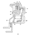
- shaft of the upper half at the time of hydraulic pressure release of the friction clutch of 1st Embodiment of this invention Sectional drawing along the axis
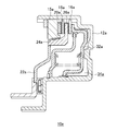
- shaft of the upper half at the time of the high hydraulic pressure of the friction clutch of FIG. Sectional drawing along the axis
- Embodiments of the present invention will be described with reference to FIGS. However, the present invention is not limited to this embodiment.
- FIG. 1 shows a state when the hydraulic pressure of the friction clutch 10 according to the first embodiment of the present invention is released.
- the friction clutch 10 is rotatably provided, and is provided on a cylindrical clutch drum 12 having an inner peripheral surface spline 14 formed on the inner peripheral side of the clutch drum 12 so as to be coaxial with the clutch drum 12 and relatively rotatable.
- the hub 22 is provided.
- the rotating shafts of the clutch drum 12 and the hub 22 are not shown, and the friction clutch 10 has a substantially symmetrical structure with respect to the rotating shaft, so FIGS. 1 to 5 show the upper half of the rotating shaft. ing.
- a pusher plate 16 and a driven plate 18 are fitted to the inner peripheral surface spline 14 of the clutch drum 12, and an input cone 15 is provided on the clutch drum 12.
- the input cone 15 is disposed by being fitted to the inner peripheral surface spline 14 and secured by the snap ring S. These rotate together with the clutch drum 12 and are arranged in the order of the pusher plate 16, the driven plate 18, and the input cone 15 in the axial direction.
- the elastic body 20 is disposed between the driven plate 18 and the input cone 15.
- the elastic body 20 is an annular wave spring, but other than the wave spring may be used as long as it is an elastic body that can be disposed between the driven plate 18 and the input cone 15.
- a piston 32 is provided on the inner peripheral side of the clutch drum 12.
- the piston 32 is configured to move in the direction of the pusher plate 16 by hydraulic oil sent from an oil passage (not shown) to a hydraulic chamber 34 provided between the piston 32 and the clutch drum 12.
- a canceller 36 is disposed on the pusher plate 16 side of the piston 32, and a return spring 37 is provided between the piston 32 and the canceller 36. For this reason, when the piston 32 is moved in the direction of the pusher plate 16 by the working oil, the return spring 37 is compressed, and when the hydraulic pressure of the working oil is released, the return spring 37 pushes the piston 32 back.
- the piston 32 is provided so as to be movable back and forth in the axial direction.
- the space between the piston 32 and the canceller 36 may be used as a canceller hydraulic chamber 38, and return hydraulic oil may be supplied to the canceller hydraulic chamber 38.
- the output cone 24 is connected to the hub 22.
- the output cone 24 is assembled with a friction plate 26 disposed between the pusher plate 16 and the driven plate 18.
- the output cone 24 and the friction plate 26 may be integrated.
- the output cone 24 is provided to be movable in the axial direction with respect to the hub 22.
- the input cone 15 and the output cone 24 are friction engaging surfaces, and a friction material can be attached to either one of the conical surfaces. The same applies to a second input cone 42, a third input cone 44b, and a second output cone 46b, which will be described later.
- the piston 32 When the piston 32 is operated at a low hydraulic pressure, the piston 32 presses the pusher plate 16 to frictionally engage the pusher plate 16, the friction plate 26, and the driven plate 18, and compress the elastic body 20. In this manner, in the friction clutch 10, the torque of the clutch drum 12 is first transmitted to the hub 22 by the disk clutch constituted by the pusher plate 16, the friction plate 26, and the driven plate 18 by the operation of the piston 32.
- the elastic body 20 is compressed when the pusher plate 16, the friction plate 26, and the driven plate 18 are frictionally engaged, so that the shock at the initial stage of the friction engagement of the pusher plate 16, the friction plate 26, and the driven plate 18 is alleviated. .
- the friction clutch 10 includes a second input cone 42 which is fitted between the pusher plate 16 and the piston 32 and is fitted to the inner peripheral surface spline 14 of the clutch drum 12.
- the second input cone 42 is configured to frictionally engage with a surface opposite to the surface of the output cone 24 with which the output cone 24 and the input cone 15 are engaged.
- the second input cone 42 may be formed integrally with the pusher plate 16.
- the hub 22 of the friction clutch 10 can be configured to have the bending portion 28.
- the bending portion 28 is configured to be elastically deformed by being pressed by the output cone 24 when the output cone 24 moves in a direction in which the output cone 24 is frictionally engaged with the input cone 15. According to this configuration, when the hydraulic pressure is released, the elastically deformed deflecting portion 28 acts to push the output cone 24 back in the direction away from the input cone 15, so that the cone clutch is more difficult to stick.
- FIG. 4 shows a friction clutch 10a according to a second embodiment of the present invention, which includes a cone clutch that transmits torque by friction engagement of one conical surface.
- the friction clutch 10 a basically has the same configuration as the friction clutch 10. However, unlike the friction clutch 10, the second input cone 42 (see FIG. 1) is not provided.
- the present invention can have such a simple configuration.
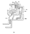
- FIG. 5 shows a friction clutch 10b according to a third embodiment of the present invention that includes a cone clutch that transmits torque by frictional engagement of three conical surfaces.
- the friction clutch 10 b basically has the same configuration as that of the friction clutch 10. However, it differs in the following points.
- the friction clutch 10b includes a third input cone 44b in which the input cone 15b frictionally engages with a surface opposite to the surface of the output cone 24b with which the output cone 24b and the input cone 15b are engaged.
- the hub 22b is linked to the output cone 24b, and is connected to the second output cone 46b that frictionally engages the surface opposite to the surface of the third input cone 44b where the output cone 24b and the third input cone 44b engage.
- the second output cone 46b and the friction plate 26b are integrated, and the output cone 24b is assembled to the second output cone 46b.
- the output cone 24b is connected to the hub 22b. It is what.
- the input cone 15b and the output cone 24b, the output cone 24b and the third input cone 44b, and the third input cone 44b and the second output cone 46b, respectively, are a total of three. Since the torque can be transmitted by frictionally engaging the two conical surfaces, the capacity of the transmitted torque can be further increased.
- the hub 22b may include a bending portion 28b that is elastically deformed by being pressed by the second output cone 46b when the second output cone 46b moves in the direction of the input cone 15b. it can. Since the operation of the bending portion 28b is the same as that of the bending portion 28 of the friction clutch 10, the description thereof is omitted.
- a friction material is attached to the surfaces of the friction plates 26 to 26b facing the pusher plates 16 to 16b and the driven plates 18 to 18b.
- a friction material can be attached to the surfaces of the pusher plates 16 to 16b and the driven plates 18 to 18b facing the friction plates 26 to 26b.
Landscapes
- Engineering & Computer Science (AREA)
- General Engineering & Computer Science (AREA)
- Mechanical Engineering (AREA)
- Hydraulic Clutches, Magnetic Clutches, Fluid Clutches, And Fluid Joints (AREA)
- Mechanical Operated Clutches (AREA)
Abstract
コンパクトで伝達トルクの容量が大きく、係合時のショックが少なく、引摺りトルクが発生し難い摩擦クラッチを提供する。 摩擦クラッチ10は、低油圧でピストン32が作動すると、プッシャプレート16、摩擦板26、ドリブンプレート18を摩擦係合させるとともに弾性体20を圧縮させるので、係合時のショックが少ない。高油圧でピストン32が作動すると、入力コーン15と出力コーン24が摩擦係合するので、伝達トルクの容量を大きくすることができ、摩擦板26とドリブンプレート18の枚数を少なくすることができるので、コンパクトである。油圧開放時は、圧縮されていた弾性体20が入力コーン15と出力コーン24を離間させるように作用するので、入力コーン15と出力コーン24の貼付きを防止でき、引摺りトルクの発生を抑制できる。
Description
本発明は、自動変速機等に使用される摩擦クラッチに関する。
同軸上に相対回転可能に設けられているクラッチドラムとハブの間でトルクを伝達する摩擦クラッチとして、クラッチドラム又はハブの一方に取付けられたプレートと、クラッチドラム又はハブの他方に取付けられた摩擦板を摩擦係合させるものがある。このタイプの摩擦クラッチにおいて、伝達するトルクの容量を大きくするためには、プレートと摩擦板を密着させるピストンの作動油圧を大きくする、ピストンの押圧部の面積を大きくする、プレートと摩擦板の枚数を増やす、というような方策がある。
しかしながら、摩擦クラッチには、コンパクト化の要求もあるため、上記のような、摩擦クラッチの大型化を伴う改良は望まれていない。すなわち、コンパクトで伝達トルクの容量が大きく、さらには、引摺りトルクを抑制できる摩擦クラッチが望まれている。このような課題を解決しようとした摩擦クラッチの例として、以下に挙げるものがある。
特許文献1には、プレートと摩擦板を摩擦係合させる摩擦クラッチに、コーンクラッチとドグクラッチを組合せたものが開示されている。この摩擦クラッチによれば、ピストンを作動させ、まず、コーンクラッチの円錐面同士を摩擦係合させ、次いで、ドグクラッチの歯を噛み合わせ、最終的に、プレートと摩擦板をピストンによって密着させるとされている。そして、この構成により、伝達トルクの容量が大きく、引摺りトルクを抑制することができるとされている。
しかし、摩擦クラッチには、係合時のショックを緩和させることや、油圧制御に連動したトルク伝達という良好な応答性も求められている。この点、特許文献1の摩擦クラッチは、コーンクラッチの摩擦係合時に急にトルク伝達がなされ、ショックが起こる可能性があり、油圧解放時には、最終的に摩擦係合が解除されるコーンクラッチが貼付き、摩擦係合状態が解除されず、この点で引摺りトルクが発生するという問題も生じ得る。
そこで、本発明は、前述した従来技術の問題点に鑑み、コンパクトで伝達トルクの容量が大きく、係合時のショックが少なく、引摺りトルクが発生し難い摩擦クラッチを提供することを目的とする。
本発明は、回転可能に設けられ、内周面スプラインが形成されている円柱状のクラッチドラムと、
前記クラッチドラムと同軸、且つ、相対回転可能に該クラッチドラムの内周側に設けられているハブと、
前記内周面スプラインに嵌合しているプッシャプレート及びドリブンプレートと、前記クラッチドラムに設けられている入力コーンが、軸方向に前記プッシャプレート、ドリブンプレート、入力コーンの順に配設され、
前記ドリブンプレートと入力コーンの間に位置する弾性体と、
前記クラッチドラムの内周側に設けられ、軸方向に進退動し、前記プッシャプレートを前記ドリブンプレート方向に押圧するピストンと、
前記ハブに連結されている出力コーンと、
前記出力コーンに組付けられ、前記プッシャプレートとドリブンプレートの間に配設されている摩擦板を具え、
前記ピストンが前記プッシャプレートの方向に移動すると、該プッシャプレートを押圧し、前記プッシャプレート、摩擦板、ドリブンプレートを摩擦係合させるとともに前記弾性体を圧縮させ、前記プッシャプレートが同方向にさらに移動すると、前記出力コーンが入力コーンの方向に移動し、前記出力コーンと入力コーンが摩擦係合状態になることを特徴とする摩擦クラッチによって前記課題を解決した。
本発明によれば、低油圧でピストンが作動したとき、プッシャプレートを押圧し、プッシャプレート、摩擦板、ドリブンプレートを摩擦係合させるとともに弾性体を圧縮させる。ここで、弾性体が圧縮することにより、プッシャプレート、摩擦板、ドリブンプレートの摩擦係合初期のショックが緩和される。また、高油圧でピストンが作動したときは、弾性体がさらに圧縮され、出力コーンが入力コーンの方向へ移動し、入力コーンと出力コーンが摩擦係合状態になる。このように、入力コーンと出力コーンから構成されるコーンクラッチでトルク伝達を行うことにより、伝達トルクの容量を大きくすることができるので、摩擦板とドリブンプレートの枚数を少なくでき、ピストンを小型化することもできる。よって、摩擦クラッチのコンパクト化を図ることができる。また、ピストンの作動に必要な作動油の油圧を低いものに設定することができるので、燃費の向上にも寄与する。また、油圧解放時、圧縮されていた弾性体が入力コーンと出力コーンを互いに離間する方向に押すように作用するので、コーンクラッチが貼付き難い。よって、引摺りトルクの発生を抑えることができる。
また、内周面スプラインに嵌合する、出力コーンと入力コーンが係合する出力コーンの面の反対側の面に摩擦係合する第二入力コーンをさらに具える構成とすれば、2つの円錐面の摩擦係合でトルクを伝達することができるので、伝達トルクの容量をさらに大きくすることができる。
ここで、ハブが、出力コーンの入力コーン方向への移動時に、出力コーンによって押圧されることによって弾性変形する撓み部を具える構成とすれば、油圧解放時、弾性変形していた撓み部が出力コーンを入力コーンから離れる方向に押戻すように作用するので、コーンクラッチが一層貼付き難い。
一方、入力コーンが、出力コーンと入力コーンが係合する出力コーンの面の反対側の面に摩擦係合する第三入力コーンを具え、ハブが、出力コーンと連動し、出力コーンと第三入力コーンが係合する第三入力コーンの面の反対側の面に摩擦係合する第二出力コーンと連結されている構成とすれば、3つの円錐面の摩擦係合でトルクを伝達することができるので、伝達トルクの容量をさらに大きくすることができる。
ここで、ハブが、第二出力コーンの入力コーン方向への移動時に、第二出力コーンによって押圧されることによって弾性変形する撓み部を具える構成とすれば、油圧解放時、弾性変形していた撓み部が出力コーンと第2出力コーンを入力コーンと第三入力コーンのそれぞれから離れる方向に押戻すように作用するので、コーンクラッチが一層貼付き難い。
本発明の実施例を、図1~5を参照して説明する。但し、本発明はこの実施形態に限定されるものではない。
図1は、本発明の第1実施形態の摩擦クラッチ10の油圧解放時の状態を示している。摩擦クラッチ10は、回転可能に設けられ、内周面スプライン14が形成されている円柱状のクラッチドラム12と、クラッチドラム12と同軸、且つ、相対回転可能にクラッチドラム12の内周側に設けられているハブ22を具えている。クラッチドラム12とハブ22の回転軸は図示を省略しており、摩擦クラッチ10は、当該回転軸に対して略対称の構造であるため、図1~5は、当該回転軸の上側半分を示している。
クラッチドラム12の内周面スプライン14には、プッシャプレート16とドリブンプレート18が嵌合しており、さらに、クラッチドラム12には、入力コーン15が設けられている。入力コーン15は、内周面スプライン14に嵌合し、スナップリングSで抜止めされることで配設されている。これらは、クラッチドラム12とともに回転し、軸方向に、プッシャプレート16、ドリブンプレート18、入力コーン15の順に配設されている。
ドリブンプレート18と入力コーン15の間には、弾性体20が配設されている。弾性体20は、環状のウェーブスプリングであるが、ドリブンプレート18と入力コーン15の間に配設できる弾性体であれば、ウェーブスプリング以外のものを使用してもよい。
クラッチドラム12の内周側には、ピストン32が設けられている。ピストン32は、ピストン32とクラッチドラム12の間に設けられる油圧室34に図示しない油路から送られる作動油によって、プッシャプレート16方向に移動するように構成されている。ピストン32のプッシャプレート16側には、キャンセラ36が配設されており、ピストン32とキャンセラ36の間にはリターンスプリング37が設けられている。このため、ピストン32が作動油によってプッシャプレート16方向に移動すると、リターンスプリング37が圧縮し、作動油の油圧が解放されたとき、リターンスプリング37がピストン32を押戻す。かくして、ピストン32は、軸方向に進退動可能に設けられている。なお、ピストン32とキャンセラ36の間の空間をキャンセラ油圧室38として、キャンセラ油圧室38にリターン用の作動油を供給するような構造としてもよい。
ハブ22には、出力コーン24が連結されている。そして、出力コーン24には、プッシャプレート16とドリブンプレート18の間に配設される摩擦板26が組付けられている。出力コーン24と摩擦板26は、一体型のものであってもよい。ここで、出力コーン24は、ハブ22に対し、軸方向移動可能に設けられている。入力コーン15と出力コーン24は、摩擦係合する面であって、いずれか一方の円錐面には、摩擦材を貼付けることができる。これは、後述する、第二入力コーン42、第三入力コーン44b、第二出力コーン46bも同様である。
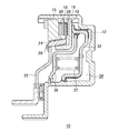
以下に、摩擦クラッチ10の作動について説明する。図2に示す様に、油圧室34に作動油が供給されると、ピストン32がプッシャプレート16の方向に移動し、第二入力コーン42を介してプッシャプレート16をドリブンプレート18の方向に押圧する。このとき、ピストン32とキャンセラ26の間に設けられているリターンスプリング37も圧縮され始める。なお、第二入力コーン42については、後に詳述する。
低油圧でピストン32が作動したとき、ピストン32がプッシャプレート16を押圧することにより、プッシャプレート16、摩擦板26、ドリブンプレート18を摩擦係合させるとともに弾性体20を圧縮させる。このように、摩擦クラッチ10では、ピストン32の作動により、まず、プッシャプレート16、摩擦板26、ドリブンプレート18から構成されるディスククラッチによってクラッチドラム12のトルクをハブ22に伝達させる。ここで、プッシャプレート16、摩擦板26、ドリブンプレート18の摩擦係合時に弾性体20が圧縮することにより、プッシャプレート16、摩擦板26、ドリブンプレート18の摩擦係合初期のショックが緩和される。
低油圧の状態から高油圧の状態へ移行したとき、図3に示すように、ピストン32はプッシャプレート16を同方向にさらに押圧する。そうすると、弾性体20はさらに圧縮されるとともに、出力コーン24が入力コーン15の方向へ移動する。そして、入力コーン15と出力コーン24が摩擦係合状態になることによって、入力コーン15と出力コーン24から構成されるコーンクラッチでトルク伝達が行われる。本構成により、摩擦クラッチ10の伝達トルクの容量を大きくすることができるので、摩擦板26とドリブンプレート18の枚数を少なくすることができ、ピストン32を小型化することもできる。本実施形態では、摩擦板26とドリブンプレート18はともに1枚である。よって、摩擦クラッチ10のコンパクト化を図ることができる。加えて、ピストン32の作動に必要な作動油の油圧を低いものに設定することができるので、燃費の向上にも寄与することができる。なお、耐熱性を向上させる等の目的で、摩擦板26とドリブンプレート18の枚数を増やすことも可能である。
また、摩擦クラッチ10は、プッシャプレート16とピストン32の間に、クラッチドラム12の内周面スプライン14に嵌合する第二入力コーン42を具えている。高油圧でピストン32が作動したとき、第二入力コーン42は、出力コーン24と入力コーン15が係合する出力コーン24の面の反対側の面に摩擦係合するように構成されている。これにより、摩擦クラッチ10は、入力コーン15及び第二入力コーン42と出力コーン24のそれぞれの2つの円錐面の摩擦係合でトルクを伝達することができるので、伝達トルクの容量をさらに大きくすることができる。なお、第二入力コーン42は、プッシャプレート16と一体的に形成されているものでもよい。
図3に示す状態から油圧が解放されたとき、ピストン32は、圧縮されていたリターンスプリング37によって押戻される。また、同様に、圧縮されていた弾性体20が入力コーン15とドリブンプレート18、摩擦板26、延いては出力コーン24を互いに離間する方向に押すように作用する。また、プッシャプレート16と出力コーン24をピストン32の方向に押戻す。これにより、コーンクラッチとディスククラッチの摩擦係合状態は解除される。このように、摩擦クラッチ10では、弾性体20が入力コーン15と出力コーン24を互いに離間する方向に押すので、コーンクラッチが貼付き難く、良好な応答性を実現できる。
また、摩擦クラッチ10のハブ22が撓み部28を有する構成とすることができる。撓み部28は、出力コーン24が入力コーン15と摩擦係合する方向へ移動したときに、出力コーン24によって押圧されることによって弾性変形するように構成されている。本構成によれば、油圧解放時、弾性変形していた撓み部28が出力コーン24を入力コーン15から離れる方向に押戻すように作用するので、コーンクラッチが一層貼付き難い。
図4には、1つの円錐面の摩擦係合でトルクを伝達するコーンクラッチを具えた、本発明の第2実施形態の摩擦クラッチ10aが示されている。摩擦クラッチ10aは、基本的には、摩擦クラッチ10と同様の構成を具えている。しかし、摩擦クラッチ10と異なり、第二入力コーン42(図1参照)を具えていない。本発明は、このようなシンプルな構成とすることもできる。
図5には、3つの円錐面の摩擦係合でトルクを伝達するコーンクラッチを具えた、本発明の第3実施形態の摩擦クラッチ10bが示されている。摩擦クラッチ10bは、基本的には、摩擦クラッチ10と同様の構成を具えている。しかし、以下の点で異なる。
摩擦クラッチ10bは、入力コーン15bが、出力コーン24bと入力コーン15bが係合する出力コーン24bの面の反対側の面に摩擦係合する第三入力コーン44bを具えている。また、ハブ22bが、出力コーン24bと連動し、出力コーン24bと第三入力コーン44bが係合する第三入力コーン44bの面の反対側の面に摩擦係合する第二出力コーン46bと連結されている。摩擦クラッチ10bでは、第二出力コーン46bと摩擦板26bが一体のもので、第二出力コーン46bに出力コーン24bが組付けられていることにより、結果として、出力コーン24bをハブ22bに連結しているものである。
摩擦クラッチ10bによれば、高油圧でピストン32bが作動したとき、入力コーン15bと出力コーン24b、出力コーン24bと第三入力コーン44b、第三入力コーン44bと第二出力コーン46bのそれぞれ合計3つの円錐面を摩擦係合させてトルクを伝達させることができるので、伝達トルクの容量をさらに大きくすることができる。
摩擦クラッチ10bの場合、ハブ22bが、第二出力コーン46bの入力コーン15b方向への移動時に、第二出力コーン46bによって押圧されることによって弾性変形する撓み部28bを具える構成とすることもできる。撓み部28bの作用については、摩擦クラッチ10の撓み部28と同様であるため、説明を省略する。
上記に説明した摩擦クラッチ10~10bでは、摩擦板26~26bのプッシャプレート16~16bとドリブンプレート18~18bに対向する面に摩擦材が貼付けられている。これに換えて、プッシャプレート16~16bとドリブンプレート18~18bの摩擦板26~26bに対向する面に摩擦材を貼付けることもできる。
以上に説明した通り、本発明によれば、コンパクトで伝達トルクの容量が大きく、係合時のショックが少なく、引摺りトルクが発生し難い摩擦クラッチとすることができる。
10~10b クラッチ
12~12b クラッチドラム
14 内周面スプライン
15~15b 入力コーン
16~16b プッシャプレート
18~18b ドリブンプレート
20~20b 弾性体
22~22b ハブ
24~24b 出力コーン
26~26b 摩擦板
28,28b 撓み部
32~32b ピストン
42 第二入力コーン
44 第三入力コーン
46b 第二出力コーン
12~12b クラッチドラム
14 内周面スプライン
15~15b 入力コーン
16~16b プッシャプレート
18~18b ドリブンプレート
20~20b 弾性体
22~22b ハブ
24~24b 出力コーン
26~26b 摩擦板
28,28b 撓み部
32~32b ピストン
42 第二入力コーン
44 第三入力コーン
46b 第二出力コーン
Claims (5)
- 回転可能に設けられ、内周面スプラインが形成されている円柱状のクラッチドラムと、
前記クラッチドラムと同軸、且つ、相対回転可能に該クラッチドラムの内周側に設けられているハブと、
前記内周面スプラインに嵌合しているプッシャプレート及びドリブンプレートと、前記クラッチドラムに設けられている入力コーンが、軸方向に前記プッシャプレート、ドリブンプレート、入力コーンの順に配設され、
前記ドリブンプレートと入力コーンの間に位置する弾性体と、
前記クラッチドラムの内周側に設けられ、軸方向に進退動し、前記プッシャプレートを前記ドリブンプレート方向に押圧するピストンと、
前記ハブに連結されている出力コーンと、
前記出力コーンに組付けられ、前記プッシャプレートとドリブンプレートの間に配設されている摩擦板を具え、
前記ピストンが前記プッシャプレートの方向に移動すると、該プッシャプレートを押圧し、前記プッシャプレート、摩擦板、ドリブンプレートを摩擦係合させるとともに前記弾性体を圧縮させ、前記プッシャプレートが同方向にさらに移動すると、前記出力コーンが入力コーンの方向に移動し、前記出力コーンと入力コーンが摩擦係合状態になることを特徴とする、
摩擦クラッチ。 - 前記内周面スプラインに嵌合する、前記出力コーンと入力コーンが係合する前記出力コーンの面の反対側の面に摩擦係合する第二入力コーンをさらに具える、請求項1の摩擦クラッチ。
- 前記ハブが、前記出力コーンの入力コーン方向への移動時に、該出力コーンによって押圧されることによって弾性変形する撓み部を具える、請求項1又は2の摩擦クラッチ。
- 前記入力コーンが、前記出力コーンと入力コーンが係合する前記出力コーンの面の反対側の面に摩擦係合する第三入力コーンを具え、
前記ハブが、前記出力コーンと連動し、該出力コーンと前記第三入力コーンが係合する該第三入力コーンの面の反対側の面に摩擦係合する第二出力コーンと連結されている、請求項1の摩擦クラッチ。 - 前記ハブが、前記第二出力コーンの入力コーン方向への移動時に、該第二出力コーンによって押圧されることによって弾性変形する撓み部を具える、請求項1又は2の摩擦クラッチ。
Priority Applications (1)
| Application Number | Priority Date | Filing Date | Title |
|---|---|---|---|
| EP18906451.2A EP3722632B1 (en) | 2018-02-15 | 2018-11-19 | Friction clutch |
Applications Claiming Priority (2)
| Application Number | Priority Date | Filing Date | Title |
|---|---|---|---|
| JP2018-024990 | 2018-02-15 | ||
| JP2018024990A JP6951273B2 (ja) | 2018-02-15 | 2018-02-15 | 摩擦クラッチ |
Publications (1)
| Publication Number | Publication Date |
|---|---|
| WO2019159461A1 true WO2019159461A1 (ja) | 2019-08-22 |
Family
ID=67620054
Family Applications (1)
| Application Number | Title | Priority Date | Filing Date |
|---|---|---|---|
| PCT/JP2018/042591 Ceased WO2019159461A1 (ja) | 2018-02-15 | 2018-11-19 | 摩擦クラッチ |
Country Status (3)
| Country | Link |
|---|---|
| EP (1) | EP3722632B1 (ja) |
| JP (1) | JP6951273B2 (ja) |
| WO (1) | WO2019159461A1 (ja) |
Families Citing this family (3)
| Publication number | Priority date | Publication date | Assignee | Title |
|---|---|---|---|---|
| US10982723B1 (en) * | 2019-11-18 | 2021-04-20 | GM Global Technology Operations LLC | Friction clutch assemblies with low-drag disconnect clutch pack having cone clutch synchronizer |
| JP7639808B2 (ja) | 2020-03-04 | 2025-03-05 | ソニーグループ株式会社 | 情報処理装置、情報処理方法、およびプログラム |
| DE102021122704B3 (de) | 2021-09-02 | 2022-10-13 | Schaeffler Technologies AG & Co. KG | Mehrstufige Trennkupplung mit formschlüssig zusammengesetzter mehrteiliger Kupplungsscheibe; sowie Hybridmodul |
Citations (6)
| Publication number | Priority date | Publication date | Assignee | Title |
|---|---|---|---|---|
| JPS3011717Y1 (ja) * | 1952-12-15 | 1955-08-22 | ||
| JPS6023628A (ja) * | 1983-07-18 | 1985-02-06 | Daikin Mfg Co Ltd | クラツチ |
| DE19833397A1 (de) * | 1998-07-24 | 2000-02-10 | Daimler Chrysler Ag | Reibschlußverbindung für ein Getriebe eines Kraftfahrzeuges |
| JP2010002028A (ja) * | 2008-06-23 | 2010-01-07 | Kyowa Metal Work Co Ltd | 多段変速遊星歯車列の摩擦要素 |
| JP2017020654A (ja) | 2015-07-14 | 2017-01-26 | ヘルビガー・アントリーブシュテクニク・ホールディング・ゲゼルシャフト・ミット・ベシュレンクテル・ハフツングHOERBIGER Antriebstechnik Holding GmbH | 自動車変速機用シフト装置 |
| US20180038420A1 (en) * | 2016-08-02 | 2018-02-08 | Hoerbiger Antriebstechnik Holding Gmbh | Gear shift device for a motor vehicle transmission |
Family Cites Families (2)
| Publication number | Priority date | Publication date | Assignee | Title |
|---|---|---|---|---|
| US2393398A (en) * | 1940-01-16 | 1946-01-22 | Snow Nabstedt Gear Corp | Clutch mechanism |
| US6702081B2 (en) * | 2002-08-02 | 2004-03-09 | General Motors Corporation | Torque-transmitting assembly and method |
-
2018
- 2018-02-15 JP JP2018024990A patent/JP6951273B2/ja active Active
- 2018-11-19 EP EP18906451.2A patent/EP3722632B1/en active Active
- 2018-11-19 WO PCT/JP2018/042591 patent/WO2019159461A1/ja not_active Ceased
Patent Citations (6)
| Publication number | Priority date | Publication date | Assignee | Title |
|---|---|---|---|---|
| JPS3011717Y1 (ja) * | 1952-12-15 | 1955-08-22 | ||
| JPS6023628A (ja) * | 1983-07-18 | 1985-02-06 | Daikin Mfg Co Ltd | クラツチ |
| DE19833397A1 (de) * | 1998-07-24 | 2000-02-10 | Daimler Chrysler Ag | Reibschlußverbindung für ein Getriebe eines Kraftfahrzeuges |
| JP2010002028A (ja) * | 2008-06-23 | 2010-01-07 | Kyowa Metal Work Co Ltd | 多段変速遊星歯車列の摩擦要素 |
| JP2017020654A (ja) | 2015-07-14 | 2017-01-26 | ヘルビガー・アントリーブシュテクニク・ホールディング・ゲゼルシャフト・ミット・ベシュレンクテル・ハフツングHOERBIGER Antriebstechnik Holding GmbH | 自動車変速機用シフト装置 |
| US20180038420A1 (en) * | 2016-08-02 | 2018-02-08 | Hoerbiger Antriebstechnik Holding Gmbh | Gear shift device for a motor vehicle transmission |
Non-Patent Citations (1)
| Title |
|---|
| See also references of EP3722632A4 |
Also Published As
| Publication number | Publication date |
|---|---|
| EP3722632A4 (en) | 2021-09-29 |
| JP6951273B2 (ja) | 2021-10-20 |
| EP3722632B1 (en) | 2022-09-07 |
| EP3722632A1 (en) | 2020-10-14 |
| JP2019138448A (ja) | 2019-08-22 |
Similar Documents
| Publication | Publication Date | Title |
|---|---|---|
| US4844219A (en) | Fluid friction couplings | |
| CN110375007B (zh) | 双增益摩擦离合器 | |
| WO2019159461A1 (ja) | 摩擦クラッチ | |
| US20020144875A1 (en) | Double clutch assembly | |
| CN113167337B (zh) | 动力传递装置 | |
| JP4065178B2 (ja) | 多板摩擦式クラッチ | |
| US20160369852A1 (en) | Composite friction and dog clutch | |
| US20120012434A1 (en) | Electromagnetic clutch | |
| JP5267869B2 (ja) | クラッチ装置 | |
| JP4975723B2 (ja) | モータサイクル用クラッチ装置 | |
| US9777778B2 (en) | Engaging/disengaging mechanism of dual clutch | |
| KR20190005261A (ko) | 차량용 클러치 | |
| US7455161B2 (en) | Clutch of automatic transmission | |
| JPH0745888B2 (ja) | 油圧クラッチ構造 | |
| KR101416173B1 (ko) | 클러치 | |
| JP6368102B2 (ja) | 摩擦係合装置 | |
| JP6951281B2 (ja) | 摩擦クラッチ | |
| JP3245292B2 (ja) | クラッチプレート | |
| CN100564918C (zh) | 摩托车用离合装置 | |
| JP3215776U (ja) | デュアルクラッチ | |
| JPH05263837A (ja) | 動力取出装置の動力断接装置 | |
| KR20090054135A (ko) | 차량용 자동 변속기의 클러치 | |
| JP2017040313A (ja) | 摩擦クラッチ | |
| JP2024045968A (ja) | 多板クラッチ | |
| JP2020003049A (ja) | 動力伝達装置 |
Legal Events
| Date | Code | Title | Description |
|---|---|---|---|
| 121 | Ep: the epo has been informed by wipo that ep was designated in this application |
Ref document number: 18906451 Country of ref document: EP Kind code of ref document: A1 |
|
| ENP | Entry into the national phase |
Ref document number: 2018906451 Country of ref document: EP Effective date: 20200710 |
|
| NENP | Non-entry into the national phase |
Ref country code: DE |