WO2019159721A1 - 空気調和装置 - Google Patents
空気調和装置 Download PDFInfo
- Publication number
- WO2019159721A1 WO2019159721A1 PCT/JP2019/003693 JP2019003693W WO2019159721A1 WO 2019159721 A1 WO2019159721 A1 WO 2019159721A1 JP 2019003693 W JP2019003693 W JP 2019003693W WO 2019159721 A1 WO2019159721 A1 WO 2019159721A1
- Authority
- WO
- WIPO (PCT)
- Prior art keywords
- expansion valve
- radiation
- heat exchanger
- opening
- indoor
- Prior art date
- Legal status (The legal status is an assumption and is not a legal conclusion. Google has not performed a legal analysis and makes no representation as to the accuracy of the status listed.)
- Ceased
Links
Images
Classifications
-
- F—MECHANICAL ENGINEERING; LIGHTING; HEATING; WEAPONS; BLASTING
- F25—REFRIGERATION OR COOLING; COMBINED HEATING AND REFRIGERATION SYSTEMS; HEAT PUMP SYSTEMS; MANUFACTURE OR STORAGE OF ICE; LIQUEFACTION SOLIDIFICATION OF GASES
- F25B—REFRIGERATION MACHINES, PLANTS OR SYSTEMS; COMBINED HEATING AND REFRIGERATION SYSTEMS; HEAT PUMP SYSTEMS
- F25B13/00—Compression machines, plants or systems, with reversible cycle
-
- F—MECHANICAL ENGINEERING; LIGHTING; HEATING; WEAPONS; BLASTING
- F24—HEATING; RANGES; VENTILATING
- F24F—AIR-CONDITIONING; AIR-HUMIDIFICATION; VENTILATION; USE OF AIR CURRENTS FOR SCREENING
- F24F1/00—Room units for air-conditioning, e.g. separate or self-contained units or units receiving primary air from a central station
- F24F1/0007—Indoor units, e.g. fan coil units
- F24F1/0059—Indoor units, e.g. fan coil units characterised by heat exchangers
-
- F—MECHANICAL ENGINEERING; LIGHTING; HEATING; WEAPONS; BLASTING
- F24—HEATING; RANGES; VENTILATING
- F24F—AIR-CONDITIONING; AIR-HUMIDIFICATION; VENTILATION; USE OF AIR CURRENTS FOR SCREENING
- F24F1/00—Room units for air-conditioning, e.g. separate or self-contained units or units receiving primary air from a central station
- F24F1/0007—Indoor units, e.g. fan coil units
- F24F1/009—Indoor units, e.g. fan coil units characterised by heating arrangements
- F24F1/0093—Indoor units, e.g. fan coil units characterised by heating arrangements with additional radiant heat-discharging elements, e.g. electric heaters
-
- F—MECHANICAL ENGINEERING; LIGHTING; HEATING; WEAPONS; BLASTING
- F24—HEATING; RANGES; VENTILATING
- F24F—AIR-CONDITIONING; AIR-HUMIDIFICATION; VENTILATION; USE OF AIR CURRENTS FOR SCREENING
- F24F11/00—Control or safety arrangements
- F24F11/30—Control or safety arrangements for purposes related to the operation of the system, e.g. for safety or monitoring
- F24F11/41—Defrosting; Preventing freezing
-
- F—MECHANICAL ENGINEERING; LIGHTING; HEATING; WEAPONS; BLASTING
- F24—HEATING; RANGES; VENTILATING
- F24F—AIR-CONDITIONING; AIR-HUMIDIFICATION; VENTILATION; USE OF AIR CURRENTS FOR SCREENING
- F24F11/00—Control or safety arrangements
- F24F11/30—Control or safety arrangements for purposes related to the operation of the system, e.g. for safety or monitoring
- F24F11/41—Defrosting; Preventing freezing
- F24F11/42—Defrosting; Preventing freezing of outdoor units
-
- F—MECHANICAL ENGINEERING; LIGHTING; HEATING; WEAPONS; BLASTING
- F24—HEATING; RANGES; VENTILATING
- F24F—AIR-CONDITIONING; AIR-HUMIDIFICATION; VENTILATION; USE OF AIR CURRENTS FOR SCREENING
- F24F11/00—Control or safety arrangements
- F24F11/62—Control or safety arrangements characterised by the type of control or by internal processing, e.g. using fuzzy logic, adaptive control or estimation of values
- F24F11/63—Electronic processing
- F24F11/65—Electronic processing for selecting an operating mode
-
- F—MECHANICAL ENGINEERING; LIGHTING; HEATING; WEAPONS; BLASTING
- F24—HEATING; RANGES; VENTILATING
- F24F—AIR-CONDITIONING; AIR-HUMIDIFICATION; VENTILATION; USE OF AIR CURRENTS FOR SCREENING
- F24F11/00—Control or safety arrangements
- F24F11/89—Arrangement or mounting of control or safety devices
-
- F—MECHANICAL ENGINEERING; LIGHTING; HEATING; WEAPONS; BLASTING
- F24—HEATING; RANGES; VENTILATING
- F24F—AIR-CONDITIONING; AIR-HUMIDIFICATION; VENTILATION; USE OF AIR CURRENTS FOR SCREENING
- F24F13/00—Details common to, or for air-conditioning, air-humidification, ventilation or use of air currents for screening
- F24F13/30—Arrangement or mounting of heat-exchangers
-
- F—MECHANICAL ENGINEERING; LIGHTING; HEATING; WEAPONS; BLASTING
- F24—HEATING; RANGES; VENTILATING
- F24F—AIR-CONDITIONING; AIR-HUMIDIFICATION; VENTILATION; USE OF AIR CURRENTS FOR SCREENING
- F24F3/00—Air-conditioning systems in which conditioned primary air is supplied from one or more central stations to distributing units in the rooms or spaces where it may receive secondary treatment; Apparatus specially designed for such systems
- F24F3/06—Air-conditioning systems in which conditioned primary air is supplied from one or more central stations to distributing units in the rooms or spaces where it may receive secondary treatment; Apparatus specially designed for such systems characterised by the arrangements for the supply of heat-exchange fluid for the subsequent treatment of primary air in the room units
-
- F—MECHANICAL ENGINEERING; LIGHTING; HEATING; WEAPONS; BLASTING
- F24—HEATING; RANGES; VENTILATING
- F24F—AIR-CONDITIONING; AIR-HUMIDIFICATION; VENTILATION; USE OF AIR CURRENTS FOR SCREENING
- F24F5/00—Air-conditioning systems or apparatus not covered by F24F1/00 or F24F3/00, e.g. using solar heat or combined with household units such as an oven or water heater
- F24F5/0089—Systems using radiation from walls or panels
-
- F—MECHANICAL ENGINEERING; LIGHTING; HEATING; WEAPONS; BLASTING
- F25—REFRIGERATION OR COOLING; COMBINED HEATING AND REFRIGERATION SYSTEMS; HEAT PUMP SYSTEMS; MANUFACTURE OR STORAGE OF ICE; LIQUEFACTION SOLIDIFICATION OF GASES
- F25B—REFRIGERATION MACHINES, PLANTS OR SYSTEMS; COMBINED HEATING AND REFRIGERATION SYSTEMS; HEAT PUMP SYSTEMS
- F25B41/00—Fluid-circulation arrangements
- F25B41/20—Disposition of valves, e.g. of on-off valves or flow control valves
- F25B41/24—Arrangement of shut-off valves for disconnecting a part of the refrigerant cycle, e.g. an outdoor part
-
- F—MECHANICAL ENGINEERING; LIGHTING; HEATING; WEAPONS; BLASTING
- F25—REFRIGERATION OR COOLING; COMBINED HEATING AND REFRIGERATION SYSTEMS; HEAT PUMP SYSTEMS; MANUFACTURE OR STORAGE OF ICE; LIQUEFACTION SOLIDIFICATION OF GASES
- F25B—REFRIGERATION MACHINES, PLANTS OR SYSTEMS; COMBINED HEATING AND REFRIGERATION SYSTEMS; HEAT PUMP SYSTEMS
- F25B47/00—Arrangements for preventing or removing deposits or corrosion, not provided for in another subclass
- F25B47/02—Defrosting cycles
- F25B47/022—Defrosting cycles hot gas defrosting
- F25B47/025—Defrosting cycles hot gas defrosting by reversing the cycle
-
- F—MECHANICAL ENGINEERING; LIGHTING; HEATING; WEAPONS; BLASTING
- F25—REFRIGERATION OR COOLING; COMBINED HEATING AND REFRIGERATION SYSTEMS; HEAT PUMP SYSTEMS; MANUFACTURE OR STORAGE OF ICE; LIQUEFACTION SOLIDIFICATION OF GASES
- F25B—REFRIGERATION MACHINES, PLANTS OR SYSTEMS; COMBINED HEATING AND REFRIGERATION SYSTEMS; HEAT PUMP SYSTEMS
- F25B2313/00—Compression machines, plants or systems with reversible cycle not otherwise provided for
- F25B2313/023—Compression machines, plants or systems with reversible cycle not otherwise provided for using multiple indoor units
- F25B2313/0233—Compression machines, plants or systems with reversible cycle not otherwise provided for using multiple indoor units in parallel arrangements
-
- F—MECHANICAL ENGINEERING; LIGHTING; HEATING; WEAPONS; BLASTING
- F25—REFRIGERATION OR COOLING; COMBINED HEATING AND REFRIGERATION SYSTEMS; HEAT PUMP SYSTEMS; MANUFACTURE OR STORAGE OF ICE; LIQUEFACTION SOLIDIFICATION OF GASES
- F25B—REFRIGERATION MACHINES, PLANTS OR SYSTEMS; COMBINED HEATING AND REFRIGERATION SYSTEMS; HEAT PUMP SYSTEMS
- F25B2313/00—Compression machines, plants or systems with reversible cycle not otherwise provided for
- F25B2313/031—Sensor arrangements
- F25B2313/0314—Temperature sensors near the indoor heat exchanger
-
- F—MECHANICAL ENGINEERING; LIGHTING; HEATING; WEAPONS; BLASTING
- F25—REFRIGERATION OR COOLING; COMBINED HEATING AND REFRIGERATION SYSTEMS; HEAT PUMP SYSTEMS; MANUFACTURE OR STORAGE OF ICE; LIQUEFACTION SOLIDIFICATION OF GASES
- F25B—REFRIGERATION MACHINES, PLANTS OR SYSTEMS; COMBINED HEATING AND REFRIGERATION SYSTEMS; HEAT PUMP SYSTEMS
- F25B2500/00—Problems to be solved
- F25B2500/12—Sound
-
- F—MECHANICAL ENGINEERING; LIGHTING; HEATING; WEAPONS; BLASTING
- F25—REFRIGERATION OR COOLING; COMBINED HEATING AND REFRIGERATION SYSTEMS; HEAT PUMP SYSTEMS; MANUFACTURE OR STORAGE OF ICE; LIQUEFACTION SOLIDIFICATION OF GASES
- F25B—REFRIGERATION MACHINES, PLANTS OR SYSTEMS; COMBINED HEATING AND REFRIGERATION SYSTEMS; HEAT PUMP SYSTEMS
- F25B2600/00—Control issues
- F25B2600/25—Control of valves
- F25B2600/2513—Expansion valves
-
- F—MECHANICAL ENGINEERING; LIGHTING; HEATING; WEAPONS; BLASTING
- F25—REFRIGERATION OR COOLING; COMBINED HEATING AND REFRIGERATION SYSTEMS; HEAT PUMP SYSTEMS; MANUFACTURE OR STORAGE OF ICE; LIQUEFACTION SOLIDIFICATION OF GASES
- F25B—REFRIGERATION MACHINES, PLANTS OR SYSTEMS; COMBINED HEATING AND REFRIGERATION SYSTEMS; HEAT PUMP SYSTEMS
- F25B2700/00—Sensing or detecting of parameters; Sensors therefor
- F25B2700/19—Pressures
- F25B2700/193—Pressures of the compressor
- F25B2700/1931—Discharge pressures
-
- F—MECHANICAL ENGINEERING; LIGHTING; HEATING; WEAPONS; BLASTING
- F25—REFRIGERATION OR COOLING; COMBINED HEATING AND REFRIGERATION SYSTEMS; HEAT PUMP SYSTEMS; MANUFACTURE OR STORAGE OF ICE; LIQUEFACTION SOLIDIFICATION OF GASES
- F25B—REFRIGERATION MACHINES, PLANTS OR SYSTEMS; COMBINED HEATING AND REFRIGERATION SYSTEMS; HEAT PUMP SYSTEMS
- F25B2700/00—Sensing or detecting of parameters; Sensors therefor
- F25B2700/19—Pressures
- F25B2700/193—Pressures of the compressor
- F25B2700/1933—Suction pressures
Definitions
- This disclosure relates to an air conditioner.
- Patent Document 1 discloses an air conditioner including a radiation type indoor unit and a convection type indoor unit.
- the radiation type indoor unit and the convection type indoor unit are connected to a refrigerant circuit.
- the refrigerant radiates and condenses in the radiant indoor unit at the same time as it radiates and condenses in the convection indoor unit.
- An object of the present disclosure is to provide an air conditioner that can suppress air from being cooled by a radiation panel in a defrost cycle.
- the first mode includes a first heat exchanger (22), a second heat exchanger (31), a radiant panel (40), and an expansion valve that adjusts the flow rate of refrigerant flowing through the radiant panel (40) ( 51), a normal refrigeration cycle for cooling or heating with the radiation panel (40), and the second heat exchange with the first heat exchanger (22) as a radiator.
- 1st aspect can suppress that a refrigerant
- the second aspect is the air conditioner according to the first aspect, wherein the control unit (C1) always keeps the expansion valve (51) in a fully closed state during the defrost cycle.
- the expansion valve is always fully closed means that the expansion valve (51) is always controlled to be fully closed.
- the control attempts to fully close the expansion valve (51), but due to a response delay, the actual opening of the expansion valve (51) immediately after the start of the defrost operation. Is not included in the fully closed state, it is included in the “always fully closed state” in claim 1.
- the 2nd mode it can control that a refrigerant flows inside a radiation panel (40) in the whole period of a defrost cycle. For this reason, the surface of the first heat exchanger (22) can be defrosted while avoiding the radiation panel (40) from becoming an evaporator.
- control unit (C1) sets the opening of the expansion valve (51) to the open state at the first opening before the defrost cycle is started. It is an air conditioner characterized by doing.
- the expansion valve (51) is opened before the start of the defrost cycle. For this reason, the oil inside a radiation panel (40) can be discharged
- a fourth aspect is the air conditioner according to the third aspect, wherein the first opening is smaller than the maximum opening of the expansion valve (51).
- a fifth aspect is the air conditioner according to the fourth aspect, wherein the first opening is an opening that is 50% or more of the maximum opening of the expansion valve (51).
- control unit (C1) changes the opening degree of the expansion valve (51) stepwise before the defrost cycle is started.
- it is an air conditioner characterized by setting it as the 1st opening.
- the first heat exchanger (22) is provided in an indoor unit (30), and the second heat exchanger (31) It is an air conditioner provided in an outdoor unit (20).
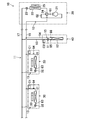
- FIG. 1 is a piping system diagram illustrating a schematic configuration of an air conditioner according to an embodiment.
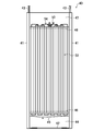
- FIG. 2 is a front view illustrating a schematic configuration of the radiation panel according to the embodiment.
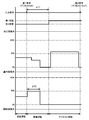
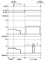
- FIG. 3 is a timing chart showing operations of the four-way switching valve, the indoor expansion valve, and the radiation expansion valve in the preparation operation and the defrost operation.
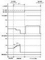
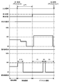
- FIG. 4 is a diagram corresponding to FIG. 3 according to the first modification.
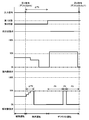
- FIG. 5 is a diagram corresponding to FIG. 3 according to the second modification.
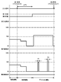
- FIG. 6 is a diagram corresponding to FIG.
- FIG. 7 is a diagram corresponding to FIG.
- FIG. 8 is a diagram corresponding to FIG.
- the air conditioner (10) performs switching between indoor cooling and heating. As shown in FIG. 1, the air conditioner (10) includes an outdoor unit (20), an indoor unit (30), and a radiation panel (40).
- the outdoor unit (20) is installed outside the room.
- the outdoor unit (20) constitutes a heat source unit.
- the outdoor unit (20) includes a compressor (21), an outdoor heat exchanger (22), an outdoor expansion valve (23), a four-way switching valve (24), and an outdoor fan (25).
- the indoor unit (30) is installed near the ceiling of the room.
- the indoor unit (30) constitutes a convection type indoor unit that performs cooling or heating by air conveyed by the indoor fan (33).
- the number of indoor units (30) is one or more.
- Each indoor unit (30) is provided with an indoor heat exchanger (31), an indoor expansion valve (32), and an indoor fan (33).
- Radiant panel (40) is installed on the floor of the room.
- the radiation panel (40) constitutes a radiation-type indoor unit that performs cooling or heating by the movement of radiant heat.
- the number of radiation panels (40) is one or more.
- the air conditioner (10) includes a refrigerant circuit (11) through which the filled refrigerant circulates. Details of the refrigerant circuit (11) will be described later.
- the overall configuration of the radiation panel (40) will be described with reference to FIG.
- the radiation panel (40) includes a pair of support columns (41), a panel body (52) (also referred to as a radiation heat exchanger (52)), and a bottom plate (42).
- One support column (41) is provided at each of the left and right ends of the radiation panel (40). Each column (41) is erected on the floor surface and extends in the vertical direction.
- the panel body (52) is provided between the pair of support posts (41). The front surface and the rear surface of the panel body (52) are exposed to the indoor space.
- the bottom plate (42) extends left and right between the pair of support columns (41) so as to be connected to the lower ends of the pair of support columns (41).
- the bottom plate (42) is fixed to the floor surface in the room via a fastening member (not shown) such as an anchor bolt.
- the upper ends of the pair of support columns (41) are connected to a ceiling-side suspension bolt (not shown) via the fixing portion (43).
- a lower housing chamber (44) is formed below the panel body (52).
- the lower storage chamber (44) is provided with a drain pan (45) for collecting condensed water generated from the panel body (52).
- the open surfaces on the front side and the rear side of the lower storage chamber (44) are respectively covered with the lower cover (46).
- Each lower cover (46) is detachably attached to, for example, the lower portion of the pair of support posts (41).
- an upper storage chamber (47) is formed above the panel body (52).
- the upper accommodation chamber (47) accommodates the liquid pipe (53) and the gas pipe (54) of the refrigerant pipe.
- a radiation expansion valve (51) (not shown in FIG. 2) is connected to the liquid pipe (53).
- the open surfaces on the front side and the rear side of the upper storage chamber (47) are covered with the upper cover (48), respectively.
- Each upper cover (48) is detachably attached to, for example, upper portions of a pair of support columns (41).
- the refrigerant circuit (11) includes an outdoor circuit (12), an indoor circuit (13), and a radiation circuit (15).
- the outdoor circuit (12) is provided in the outdoor unit (20)
- the indoor circuit (13) is provided in the indoor unit (30)
- the radiation circuit (15) is provided in the radiation panel (40).
- the indoor unit (30) and the radiation panel (40) are connected to the outdoor unit (20) via the two connecting pipes (16, 17).
- the indoor circuit (13) and the radiation circuit (15) are connected to the outdoor circuit (12) via a gas communication pipe (16) and a liquid communication pipe (17) as communication pipes.
- a compressor (21), an outdoor heat exchanger (22) (first heat exchanger), an outdoor expansion valve (23), and a four-way switching valve (24) are connected to the outdoor circuit (12).
- the compressor (21) is configured as a variable capacity type. More specifically, the refrigerant circulation amount of the refrigerant circuit (11) can be adjusted by controlling the operating frequency (rotation speed) of the compressor (21) by the inverter device.
- an outdoor fan (25) for conveying outdoor air is provided in the vicinity of the outdoor heat exchanger (22).
- the outdoor expansion valve (23) is a flow rate control valve whose opening degree is variable, and is configured by an electronic expansion valve, for example.
- the four-way switching valve (24) constitutes a switching mechanism for switching between heating operation and cooling operation.
- the four-way selector valve (24) is configured to be switchable between a first state (state indicated by a solid line in FIG. 1) and a second state (state indicated by a broken line in FIG. 1).
- the four-way switching valve (24) switches to the first state in the cooling operation and the defrost operation (details will be described later).
- the four-way switching valve (24) in the first state communicates the discharge side of the compressor (21) with the gas end of the outdoor heat exchanger (22), and at the same time communicates gas with the suction side of the compressor (21). Connect the pipe (16).
- the four-way selector valve (24) switches to the second state in the heating operation.
- the four-way switching valve (24) in the second state allows the discharge side of the compressor (21) and the gas communication pipe (16) to communicate with each other, and at the same time, the suction side of the compressor (21) and the outdoor heat exchanger (22). The gas end is communicated with.
- the outdoor circuit (12) is provided with a discharge pressure sensor (61) and a suction pressure sensor (62).
- the discharge pressure sensor (61) is provided on the discharge side of the compressor (21).
- the discharge pressure sensor (61) detects the pressure of the refrigerant discharged from the compressor (21) (the high pressure of the refrigerant circuit (11)).
- the suction pressure sensor (62) detects the pressure of the suction refrigerant of the compressor (21) (the low pressure of the refrigerant circuit (11)).
- the quantity of the indoor circuit (13) corresponds to the quantity of the indoor unit (30).
- One end (liquid end) of the indoor circuit (13) is connected to the liquid communication pipe (17).
- the other end (gas end) of the indoor circuit (13) is connected to the gas communication pipe (16).
- the indoor expansion valve (32) and the indoor heat exchanger (31) (second heat exchanger) are connected to the indoor circuit (13) in order from the liquid end to the gas end.
- the indoor expansion valve (32) is a flow rate control valve (first control valve) having a variable opening, and is constituted by an electronic expansion valve, for example.
- an indoor fan (33) that conveys indoor air is provided in the vicinity of the indoor heat exchanger (31).
- heat is exchanged between the refrigerant flowing through the indoor heat exchanger (31) and the indoor air conveyed by the indoor fan (33).
- the indoor circuit (13) is provided with a first liquid side temperature sensor (63) and a first gas side temperature sensor (64).
- the first liquid side temperature sensor (63) is provided on the liquid side of the indoor heat exchanger (31), and detects the temperature of the liquid refrigerant flowing through the indoor circuit (13).
- the first gas side temperature sensor (64) is provided on the gas side of the indoor heat exchanger (31) and detects the temperature of the gas refrigerant flowing through the indoor circuit (13).
- the quantity of the radiation circuit (15) corresponds to the quantity of the radiation panel (40).
- One end (liquid end) of the radiation circuit (15) is connected to the liquid communication pipe (17).
- the other end (gas end) of the radiation circuit (15) is connected to the gas communication pipe (16).
- a radiation expansion valve (51) and a radiation heat exchanger (52) are connected to the radiation circuit (15) in order from the liquid end to the gas end.
- the radiation expansion valve (51) is a flow rate control valve (second control valve) having a variable opening degree, and is configured by an electronic expansion valve, for example.
- no fan for conveying air is provided in the vicinity of the radiant heat exchanger (52). That is, the radiant heat exchanger (52) exchanges heat between the refrigerant and the room air by the movement of the radiant heat.
- the radiation circuit (15) is provided with a second liquid side temperature sensor (65) and a second gas side temperature sensor (66).
- the second liquid side temperature sensor (65) is provided on the liquid side (liquid pipe (53)) of the radiant heat exchanger (52) and detects the temperature of the liquid refrigerant flowing through the radiation circuit (15).
- the second gas side temperature sensor (66) is provided on the gas side (gas pipe (54)) of the radiant heat exchanger (52) and detects the temperature of the gas refrigerant flowing through the radiant circuit (15).
- the indoor unit (30) of this embodiment is provided with an indoor controller (C1), and the radiation panel (40) is provided with a radiation controller (C2) (control unit).
- Each of the indoor controller (C1) and the radiation controller (C2) is configured using a microcomputer and a memory device (specifically, a semiconductor memory) that stores software for operating the microcomputer. .
- the indoor controller (C1) and the radiation controller (C2) can input and output detection signals of various sensors, control signals, and the like.
- the indoor controller (C1) controls the start / stop (so-called thermo-on / thermo-off) of the indoor unit (30). More specifically, the indoor controller (C1) stops (thermo-off) the indoor unit (30) when the temperature Tr of the indoor air reaches a predetermined value based on the set temperature Ts.
- the indoor controller (C1) controls the degree of opening of the indoor expansion valve (32) during the cooling operation, so-called superheat degree. Specifically, in the cooling operation, the opening degree of the indoor expansion valve (32) is adjusted so that the superheat degree SH1 of the refrigerant evaporated in the indoor heat exchanger (31) approaches the target superheat degree.
- the superheat degree SH1 is obtained, for example, by the difference between the refrigerant temperature detected by the first gas side temperature sensor (64) and the saturation temperature corresponding to the low pressure detected by the suction pressure sensor (62).
- the indoor controller (C1) controls the degree of opening of the indoor expansion valve (32) during the heating operation, so-called supercooling degree. Specifically, in the heating operation, the opening degree of the indoor expansion valve (32) is adjusted so that the degree of supercooling SC1 of the refrigerant after being condensed in the indoor heat exchanger (31) approaches the target degree of supercooling. .
- the degree of supercooling SC1 is obtained, for example, by the difference between the refrigerant temperature detected by the first liquid side temperature sensor (63) and the saturation temperature corresponding to the high pressure detected by the discharge pressure sensor (61).
- the indoor controller (C1) opens the opening of the indoor expansion valve (32) at a predetermined opening in the defrost operation.
- the opening degree of the indoor expansion valve (32) at this time may be a predetermined fixed opening degree, or may be appropriately adjusted by, for example, superheat degree control.
- an indoor heat exchanger (31) functions as an evaporator.
- the radiation controller (C2) controls the degree of superheat of the opening of the radiation expansion valve (51) during cooling operation. Specifically, in the heating operation, the opening degree of the radiant expansion valve (51) is adjusted so that the superheat degree SH2 of the refrigerant evaporated by the radiant heat exchanger (52) approaches the target superheat degree.
- the superheat degree SH2 is obtained, for example, by the difference between the refrigerant temperature detected by the second gas side temperature sensor (66) and the saturation temperature corresponding to the low pressure detected by the suction pressure sensor (62).
- the radiation controller (C2) controls the degree of opening of the radiation expansion valve (51) in a so-called supercooling degree during heating operation. Specifically, in the heating operation, the opening degree of the radiation expansion valve (51) is adjusted so that the degree of supercooling SC2 of the refrigerant after being condensed in the radiant heat exchanger (52) approaches the target degree of supercooling.
- the degree of supercooling SC2 is obtained, for example, by the difference between the refrigerant temperature detected by the second liquid side temperature sensor (65) and the saturation temperature corresponding to the high pressure detected by the discharge pressure sensor (61).
- the radiation controller (C2) controls the opening of the radiation expansion valve (51) in the defrost operation and the preparatory operation that is executed immediately before the operation. Specifically, the radiation controller (C2) controls the expansion valve (51) so that the opening degree of the radiation expansion valve (51) is always fully closed in the defrost operation. In the preparation operation, the radiation controller (C2) opens the radiation expansion valve (51) at a predetermined opening (details will be described later).
- the operation of the air conditioner (10) according to Embodiment 1 will be described with reference to FIG.
- the air conditioner (10) switches between a cooling operation and a heating operation.
- ⁇ Cooling operation> In the cooling operation, the compressor (21), the outdoor fan (25), and the indoor fan (33) are operated.
- the four-way selector valve (24) is in the first state.
- the outdoor expansion valve (23) is opened to a predetermined opening (for example, fully open).
- the degree of superheat is controlled for the opening degree of the indoor expansion valve (32) and the radiation expansion valve (51).
- a refrigeration cycle is performed in which the refrigerant condensed and radiated in the outdoor heat exchanger (22) evaporates in the indoor heat exchanger (31) and the radiant heat exchanger (52) (that is, the radiant panel (40)).
- the refrigerant compressed by the compressor (21) flows through the outdoor heat exchanger (22).
- the refrigerant dissipates heat to the outdoor air and condenses.
- the refrigerant condensed in the outdoor heat exchanger (22) flows through the liquid communication pipe (17) after passing through the outdoor expansion valve (23).
- the refrigerant flowing through the liquid communication pipe (17) is divided into the indoor circuit (13) and the radiation circuit (15).
- the refrigerant flowing into the indoor circuit (13) is depressurized by the indoor expansion valve (32) and then flows through the indoor heat exchanger (31).
- the indoor heat exchanger (31) the refrigerant absorbs heat from the air conveyed by the indoor fan (33) and evaporates.
- the refrigerant evaporated in the indoor heat exchanger (31) flows out to the gas communication pipe (16).
- the refrigerant flowing into the radiation circuit (15) is depressurized by the radiation expansion valve (51) and then flows through the radiant heat exchanger (52).
- the radiant heat exchanger (52) the refrigerant absorbs heat from the room air around the radiant panel (40) and evaporates.
- the refrigerant evaporated in the radiant heat exchanger (52) flows out to the gas communication pipe (16).
- the refrigerant merged in the gas communication pipe (16) is sucked into the compressor (21) and compressed again.
- ⁇ Heating operation> In the heating operation, the compressor (21), the outdoor fan (25), and the indoor fan (33) are operated.
- the four-way selector valve (24) is in the second state.
- the outdoor expansion valve (23) is superheated.
- the degree of supercooling is controlled for the opening degree of the indoor expansion valve (32) and the radiation panel (40).
- a refrigeration cycle is performed in which the refrigerant condensed and dissipated in the indoor heat exchanger (31) and the radiant heat exchanger (52) is evaporated in the outdoor heat exchanger (22).
- the refrigerant compressed by the compressor (21) flows through the gas communication pipe (16) and is divided into an outdoor circuit (12) and a radiation circuit (15).
- the refrigerant flowing into the indoor circuit (13) flows through the indoor heat exchanger (31).
- the refrigerant dissipates heat to the air conveyed by the indoor fan (33) and condenses.
- the refrigerant condensed in the indoor heat exchanger (31) passes through the indoor expansion valve (32) and then flows out to the liquid communication pipe (17).
- the refrigerant dissipates heat to the room air around the radiant panel (40) and condenses.
- the refrigerant condensed in the radiant heat exchanger (52) passes through the radiant expansion valve (51) and then flows out to the liquid communication pipe (17).
- the refrigerant merged in the liquid communication pipe (17) flows into the outdoor circuit (12), is decompressed by the outdoor expansion valve (23), and then flows through the outdoor heat exchanger (22).
- the outdoor heat exchanger (22) the refrigerant absorbs heat from the outdoor air and evaporates.
- the refrigerant evaporated in the outdoor heat exchanger (22) is sucked into the compressor (21) and compressed again.
- frost may form on the surface of the outdoor heat exchanger (22) serving as an evaporator.
- the air conditioner (10) is configured to be able to perform a defrost operation for defrosting the outdoor heat exchanger (22).
- a refrigeration cycle (defrost cycle) is performed in which the refrigerant releases and condenses in the outdoor heat exchanger (22), and the refrigerant evaporates in the indoor heat exchanger (31).
- a preparatory operation is performed before switching from the heating operation to the defrost operation.
- an operation of discharging the oil accumulated in the radiation panel (40) together with the liquid refrigerant is performed.
- the preparation operation and the defrost operation will be described in detail with reference to FIGS. 1 and 3.
- ⁇ Preparation operation> For example, in the heating operation described above, when the condition A indicating that the surface of the outdoor heat exchanger (22) is frosted is established, the first signal for executing the defrost operation is input to each controller (C1, C2). Is done. Then, a preparation operation for shifting from the heating operation to the defrost operation starts. Here, the preparatory operation is executed until a predetermined time ⁇ T1 elapses after the first signal is input, and then shifts to the defrost operation.
- the condition A is determined based on, for example, the temperature of the refrigerant flowing through the outdoor heat exchanger (22), the temperature of the air passing through the outdoor heat exchanger (22), the execution time of the heating operation, and the like.
- the rotational speed of the compressor (21) decreases stepwise.
- the compressor (21) is stopped before the defrost operation is started.
- the opening of the indoor expansion valve (32) also decreases as the rotational speed of the compressor (21) decreases.
- the control of the opening degree of the indoor expansion valve (32) may be supercooling degree control or control of gradually reducing the target opening degree of the indoor expansion valve (32).
- the state (second state) of the four-way selector valve (24) during the heating operation is maintained as it is. Therefore, the basic refrigerant flow is the same as in the heating operation.
- the radiation controller (C2) opens the radiation expansion valve (51) at a predetermined opening (first opening) in synchronization with the first signal.
- the first opening degree of the present embodiment is set to an opening degree of 50% (for example, about 1000 pulses), assuming that the maximum opening of the radiation expansion valve (51) is 100% (for example, about 2000 pulses).
- the opening of the radiation expansion valve (51) is forcibly opened, the oil (refrigerator oil) inside the radiation panel (40) can be reliably discharged. As a result, poor lubrication of the compressor (21) can be avoided in the subsequent defrost operation.
- the radiation expansion valve (51) When the time ⁇ T2 (for example, 40 seconds) has elapsed since the opening of the radiation expansion valve (51) is changed to the first opening, the radiation expansion valve (51) is fully closed.
- ⁇ T2 is a period shorter than ⁇ T1. Thereby, the radiation expansion valve (51) is fully closed after the opening degree reaches the first opening degree and before the defrost operation is started.
- the opening corresponding to the “fully closed state” is an opening that prevents the refrigerant from substantially flowing through the inside of the radiation panel (40), and is not necessarily limited to a zero pulse opening.
- ⁇ Defrost operation> When ⁇ T1 elapses after the preparation operation is started, the defrost operation is executed. Then, the four-way switching valve (24) is switched from the second state to the first state.
- the rotational speed of the compressor (21) gradually increases to the target rotational speed.
- the indoor expansion valve (32) is opened at a predetermined opening.
- the indoor expansion valve (32) may be controlled in superheat or may be adjusted to a predetermined target opening.
- the outdoor expansion valve (23) is fully opened, for example.
- the radiation expansion valve (51) is controlled to be fully closed.
- the radiation expansion valve (51) is fully closed immediately before the start of the defrost operation. For this reason, at the start of the defrost operation, the target opening (for example, zero pulse) of the radiation expansion valve (51) is maintained as it is.
- the radiation expansion valve (51) is always controlled to be fully closed. That is, the target opening degree of the radiation expansion valve (51) is maintained at a value that satisfies the fully closed state over the entire period of the defrost operation. Note that the target opening of the radiation expansion valve (51) may be changed to a fully closed value at the same timing as the start of the defrost operation.
- defrost cycle In defrost operation, the following refrigeration cycle (defrost cycle) is basically performed.
- the refrigerant compressed by the compressor (21) flows through the outdoor heat exchanger (22).
- the refrigerant radiates heat to the frost on the surface of the outdoor heat exchanger (22).
- the frost of the outdoor heat exchanger (22) is melted.
- the refrigerant radiated and condensed in the outdoor heat exchanger (22) flows through the liquid communication pipe (17).
- the indoor expansion valve (32) In defrost operation, the indoor expansion valve (32) is opened at a predetermined opening. For this reason, the refrigerant in the liquid communication pipe (17) is depressurized by the indoor expansion valve (32) and then evaporated by the indoor heat exchanger (31). The evaporated refrigerant flows through the gas communication pipe (16) and then is sucked into the compressor (21).
- the radiation expansion valve (51) is fully closed. For this reason, the refrigerant in the liquid communication pipe (17) is not sent to the radiation circuit (15) or the radiation panel (40) (radiant heat exchanger (52)). If the refrigerant flows inside the radiation panel (40) in the defrost operation, the refrigerant evaporates at the radiation panel (40). In this case, the surface temperature of the panel body (52) is lowered, and the heating load of the indoor space is increased. Moreover, if a resident touches a panel main body (52), a resident will feel cold.
- the radiation expansion valve (51) is fully closed during the entire period of the defrost operation, it is ensured that the radiation panel (40) is cooled due to the evaporation of the refrigerant. Can be avoided. As a result, it is possible to reliably avoid an increase in the heating load and a loss of comfort of the occupants.
- the radiation expansion valve (51) is opened at the first opening. For this reason, the oil collected inside the radiation panel (40) can be discharged together with the refrigerant. For this reason, in the defrost operation, sufficient oil can be secured, and poor lubrication of the compressor (21) can be avoided.
- the defrost operation when the condition B indicating that the defrosting of the outdoor heat exchanger (22) is completed is satisfied, a second signal for ending the defrost operation is input to each controller (C1, C2). Then, the defrost operation shifts to a normal operation (heating operation).
- the condition B is determined based on, for example, the temperature of the refrigerant flowing through the outdoor heat exchanger (22), the temperature of the air passing through the outdoor heat exchanger (22), the execution time of the defrost operation, and the like.
- the radiation expansion valve (51) is always fully closed during the defrost operation. For this reason, it can avoid reliably that a refrigerant
- the indoor heat exchanger (31) is inside the indoor unit (30), even if the refrigerant evaporates, the temperature of the indoor space is not greatly affected. In particular, if the indoor fan (33) is stopped, this effect is extremely small.
- the radiation panel (40) is installed on the floor surface of the indoor space, and the panel body (52) is configured to be exposed to the indoor space. For this reason, when the radiation panel (40) becomes an evaporator, the ambient temperature of the occupant tends to decrease due to radiation. Further, since the radiant panel (40) is within the reach of the occupant, if the occupant touches the radiant panel (40), the occupant feels cold and feels uncomfortable. On the other hand, in this embodiment, it can avoid reliably that the ambient temperature of a radiation panel (40) falls or a resident feels discomfort.
- the opening of the radiation expansion valve (51) is opened at the first opening before the defrost cycle is started.
- the control unit indoor controller (C1)
- the control unit sets the radiation expansion valve (51) at the first opening before the start of the defrost operation. Leave open.
- the oil in the radiation panel (40) can be discharged and sent to the compressor (21) side.
- the radiation expansion valve (51) is always fully closed during the defrost operation, the refrigerant does not flow inside the radiation panel (40).
- discharging the oil in the radiation panel (40) in this way it is possible to avoid poor lubrication of the compressor (21) during the defrost cycle.
- the first opening is smaller than the maximum opening of the radiation expansion valve (51). If the opening of the radiant expansion valve (51) is too large, the amount of refrigerant flowing through the radiant expansion valve (51) increases, and the passing sound of the refrigerant may become noise. On the other hand, such noise can be suppressed by making the opening degree of the radiation expansion valve (51) smaller than the maximum opening degree.
- the first opening is 50% or more of the maximum opening of the radiation expansion valve (51).
- the first modification shown in FIG. 4 is different from the above embodiment in the control of the preparation operation.
- the opening degree of the radiation expansion valve (51) is changed stepwise. Specifically, when the first signal is input, the radiation controller (C2) gradually steps the target opening of the radiation expansion valve (51) closer to the final target opening (first opening). Change. Thereby, the opening degree of a radiation expansion valve (51) changes gradually so that it may converge to a 1st opening degree. Thereafter, when ⁇ T2 elapses, the radiation expansion valve (51) is fully closed.
- the opening degree of the radiation expansion valve (51) changes stepwise, it is possible to prevent the opening degree of the radiation expansion valve (51) from increasing sharply.
- the opening degree of the radiation expansion valve (51) increases sharply, a large amount of liquid refrigerant may pass through the radiation expansion valve (51), thereby generating noise.
- the radiation expansion valve (51) is gradually opened, the flow rate of the refrigerant flowing instantaneously through the radiation expansion valve (51) can be reduced.
- gradually increasing the opening of the radiation expansion valve (51) in this way can gradually reduce the degree of supercooling of the refrigerant flowing through the radiation panel (40) in the preparatory operation, so that the gas-liquid two-phase state is reached. Transition can be made.
- the passage sound of the refrigerant in the radiation expansion valve (51) can be reduced.
- the target opening may be substantially changed linearly by shortening the period during which the target opening is changed stepwise.
- Modification 2 shown in FIG. 5 is different from the above embodiment in control.
- ⁇ Preparation operation> For example, in the heating operation described above, when the condition A indicating that the surface of the outdoor heat exchanger (22) is frosted is established, the first signal for executing the defrost operation is input to each controller (C1, C2). Is done. Then, a preparation operation for shifting from the heating operation to the defrost operation starts. Here, the preparatory operation is executed until a predetermined time ⁇ T1 elapses after the first signal is input, and then shifts to the defrost operation.
- the condition A is determined based on, for example, the temperature of the refrigerant flowing through the outdoor heat exchanger (22), the temperature of the air passing through the outdoor heat exchanger (22), the execution time of the heating operation, and the like.
- the rotational speed of the compressor (21) decreases stepwise.
- the compressor (21) is stopped before the defrost operation is started.
- the opening of the indoor expansion valve (32) also decreases as the rotational speed of the compressor (21) decreases.
- the control of the opening degree of the indoor expansion valve (32) may be supercooling degree control or control of gradually reducing the target opening degree of the indoor expansion valve (32).
- the state (second state) of the four-way selector valve (24) during the heating operation is maintained as it is. Therefore, the basic refrigerant flow is the same as in the heating operation.
- the radiation controller (C2) performs control to reduce the opening of the radiation expansion valve (51) as the rotational speed of the compressor (21) decreases.
- the control of the opening degree of the radiation expansion valve (51) may be supercooling degree control or control of gradually decreasing the target opening degree of the indoor expansion valve (32).
- ⁇ Defrost operation> When ⁇ T1 elapses after the preparation operation is started, the defrost operation is executed. Then, the four-way switching valve (24) is switched from the second state to the first state.
- the rotational speed of the compressor (21) gradually increases to the target rotational speed.
- the indoor expansion valve (32) is opened at a predetermined opening.
- the indoor expansion valve (32) may be controlled in superheat or may be adjusted to a predetermined target opening.
- the outdoor expansion valve (23) is fully opened, for example.
- the radiation controller (C2) temporarily opens the radiation expansion valve (51) and fully closes the radiation expansion valve (51) for the remaining period.
- the radiation expansion valve (51) is controlled to be fully closed in a part of the period (periods P1 and P3 in FIG. 3), and in the other period (period P2 in FIG. 3), the radiation expansion valve ( 51) is controlled to the open state.
- the opening corresponding to the “fully closed state” is an opening that prevents the refrigerant from substantially flowing inside the radiation panel (40), and is not necessarily limited to the zero pulse opening.
- the following refrigeration cycle (defrost cycle) is basically performed.
- the refrigerant compressed by the compressor (21) flows through the outdoor heat exchanger (22).
- the refrigerant radiates heat to the frost on the surface of the outdoor heat exchanger (22).
- the frost of the outdoor heat exchanger (22) is melted.
- the refrigerant radiated and condensed in the outdoor heat exchanger (22) flows through the liquid communication pipe (17).
- the indoor expansion valve (32) In defrost operation, the indoor expansion valve (32) is opened at a predetermined opening. For this reason, the refrigerant in the liquid communication pipe (17) is depressurized by the indoor expansion valve (32) and then evaporated by the indoor heat exchanger (31). The evaporated refrigerant flows through the gas communication pipe (16) and then is sucked into the compressor (21).
- the radiation expansion valve (51) is fully closed. For this reason, the refrigerant in the liquid communication pipe (17) is not sent to the radiation circuit (15) or the radiation panel (40) (radiant heat exchanger (52)). If the refrigerant flows inside the radiation panel (40), the refrigerant evaporates at the radiation panel (40). In this case, the surface temperature of the panel body (52) is lowered, and the heating load of the indoor space is increased. Moreover, if a resident touches a panel main body (52), a resident will feel cold.
- the radiation expansion valve (51) is fully closed in the period P1 and the period P3. Therefore, in these periods, the radiation panel (40) is cooled due to the evaporation of the refrigerant. It can be avoided reliably. As a result, it is possible to reliably avoid an increase in the heating load and a loss of comfort of the occupants.
- the radiation expansion valve (51) is in the fully closed state over the entire period of the defrost operation, oil (refrigeration oil) accumulates inside the radiation expansion valve (51). There may be a shortage of oil to return. Therefore, in the defrost operation, the radiation expansion valve (51) is opened at the second opening degree during a part of the period (period P2). For this reason, in the period P2, the oil accumulated inside the radiation panel (40) can be discharged together with the refrigerant. As a result, in the defrost operation, sufficient oil can be secured, and poor lubrication of the compressor (21) can be avoided.
- the second opening degree of the present embodiment is set to an opening degree of 50% (for example, about 1000 pulses), assuming that the maximum opening degree of the radiation expansion valve (51) is 100% (for example, about 2000 pulses).
- the defrost operation when the condition B indicating that the defrosting of the outdoor heat exchanger (22) is completed is satisfied, a second signal for ending the defrost operation is input to each controller (C1, C2). Then, the defrost operation shifts to a normal operation (heating operation).
- the condition B is determined based on, for example, the temperature of the refrigerant flowing through the outdoor heat exchanger (22), the temperature of the air passing through the outdoor heat exchanger (22), the execution time of the defrost operation, and the like.
- the radiation expansion valve (51) is fully closed during a part of the periods (periods P1 and P3), and the radiation expansion valve (51) during the other period (period P2). Is opened. For this reason, it can avoid reliably that a refrigerant
- the indoor heat exchanger (31) is inside the indoor unit (30), even if the refrigerant evaporates, the temperature of the indoor space is not greatly affected. In particular, if the indoor fan (33) is stopped, this effect is extremely small.
- the radiation panel (40) is installed on the floor surface of the indoor space, and the panel body (52) is configured to be exposed to the indoor space. For this reason, when the radiation panel (40) becomes an evaporator, the ambient temperature of the occupant tends to decrease due to radiation. Further, since the radiant panel (40) is within the reach of the occupant, if the occupant touches the radiant panel (40), the occupant feels cold and feels uncomfortable. On the other hand, in this embodiment, it can avoid reliably that the ambient temperature of a radiation panel (40) falls or an occupant feels discomfort in periods P1 and P3.
- the second opening is smaller than the maximum opening of the radiation expansion valve (51). If the opening of the radiant expansion valve (51) is too large, the amount of refrigerant flowing through the radiant expansion valve (51) increases, and the passing sound of the refrigerant may become noise. On the other hand, such noise can be suppressed by making the opening degree of the radiation expansion valve (51) smaller than the maximum opening degree.
- the second opening is 50% or more of the maximum opening of the radiation expansion valve (51).
- Modification 3 shown in FIG. 6 differs from the above embodiment in control.
- the radiation controller (C2) opens the radiation expansion valve (51) at a predetermined opening (first opening) in synchronization with the first signal.
- the first opening degree of Modification 3 is set to an opening degree of 50% (for example, about 1000 pulses), assuming that the maximum opening of the radiation expansion valve (51) is 100% (for example, about 2000 pulses).
- the opening of the radiation expansion valve (51) is forcibly opened, the oil (refrigerator oil) inside the radiation panel (40) can be reliably discharged. As a result, poor lubrication of the compressor (21) can be avoided in the subsequent defrost operation.
- the radiation expansion valve (51) When the opening of the radiation expansion valve (51) is changed to the first opening, when the time ⁇ T2 has elapsed, the radiation expansion valve (51) is fully closed. ⁇ T2 is a period shorter than ⁇ T1. Thereby, the radiation expansion valve (51) is fully closed after the opening degree reaches the first opening degree and before the defrost operation is started.
- the opening of the radiation expansion valve (51) is opened at the first opening before the defrost cycle is started.
- the oil in a radiation panel (40) can be discharged
- the first opening is smaller than the maximum opening of the radiation expansion valve (51). If the opening of the radiant expansion valve (51) is too large, the amount of refrigerant flowing through the radiant expansion valve (51) increases, and the passing sound of the refrigerant may become noise. On the other hand, such noise can be suppressed by making the opening degree of the radiation expansion valve (51) smaller than the maximum opening degree.
- the first opening is 50% or more of the maximum opening of the radiation expansion valve (51).
- Modification 4 shown in FIG. 7 is different from the above embodiment in control.
- the opening degree of the radiation expansion valve (51) is changed stepwise. Specifically, when the first signal is input, the radiation controller (C2) gradually steps the target opening of the radiation expansion valve (51) closer to the final target opening (first opening). Change. Thereby, the opening degree of a radiation expansion valve (51) changes gradually so that it may converge to a 1st opening degree. Thereafter, when ⁇ T2 elapses, the radiation expansion valve (51) is fully closed.
- the passage sound of the refrigerant in the radiation expansion valve (51) can be reduced.
- the target opening may be substantially changed linearly by shortening the period during which the target opening is changed stepwise.
- the radiation expansion valve (51) in the defrost operation, is opened in a plurality of periods (in this example, two periods P2 and P4).
- the radiation expansion valve (51) in the period P2, is opened at the second opening (for example, 50% of the fully opened opening).
- the radiation expansion valve (51) is opened at an opening larger than the second opening. In this way, in the defrost operation, the radiation expansion valve (51) is opened at the first opening during a certain period, and the radiation expansion valve (51) is opened at an opening different from the first opening during another period. Also good.
- the indoor heat exchanger (31) and the radiant panel (40) are all radiators for heating operation, the indoor heat exchanger (31) and the radiant panel (40) Cooling operation is performed in which everything is an evaporator.
- the air conditioner (10) is a method (so-called cooling / heating free type) that performs simultaneous cooling operation in which one of the indoor heat exchanger (31) and the radiation panel (40) is an evaporator and the other is a condenser. Also good.
- the number of connecting pipes may be two or three.
- the air conditioner (10) is a system in which the radiation panel (40) (strictly, the radiant heat exchanger (52)) and the indoor heat exchanger (31) are accommodated in one unit (for example, a floor-standing unit). May be.
- the air conditioner (10) may include a heat exchanger (first heat exchanger) dedicated to the defrost operation while the indoor heat exchanger (31) is omitted.
- a heat exchanger first heat exchanger
- the outdoor heat exchanger (22) serves as a radiator and the radiation panel (40) serves as an evaporator.
- a refrigeration cycle is performed in which the radiation panel (40) serves as a radiator and the outdoor heat exchanger (22) serves as an evaporator.
- the indoor unit (30) can be installed on the floor or wall-mounted on the wall, in addition to the ceiling-mounted type (strictly, ceiling-suspended type or ceiling-mounted type) provided on the ceiling side. It may be a formula.
- the radiation panel (40) may be a ceiling-mounted type provided on the ceiling side or a wall-mounted type installed on a wall surface, in addition to the floor-standing type.
- the present disclosure is useful for an air conditioner.
Landscapes
- Engineering & Computer Science (AREA)
- Mechanical Engineering (AREA)
- General Engineering & Computer Science (AREA)
- Chemical & Material Sciences (AREA)
- Combustion & Propulsion (AREA)
- Physics & Mathematics (AREA)
- Thermal Sciences (AREA)
- Signal Processing (AREA)
- Sustainable Development (AREA)
- Life Sciences & Earth Sciences (AREA)
- Fuzzy Systems (AREA)
- Mathematical Physics (AREA)
- Air Conditioning Control Device (AREA)
Abstract
空気調和装置(10)は、第1熱交換器(22)と、第2熱交換器(31)と、輻射パネル(40)と、輻射パネル(40)を流れる冷媒の流量を調節する膨張弁(51)とが接続される冷媒回路(11)と、輻射パネル(40)で冷房又は暖房を行う通常の冷凍サイクルと、第1熱交換器(22)を放熱器とし前記第2熱交換器(31)を蒸発器とするデフロストサイクルとを切り換えるための制御部(C1)とを備える。制御部(C1)は、デフロストサイクル中において、膨張弁(51)を全閉状態とする。
Description
本開示は、空気調和装置に関する。
特許文献1には、輻射型室内機と対流型室内機とを備えた空気調和装置が開示されている。輻射型室内機と、対流型室内機とは、冷媒回路に接続される。例えば暖房運転では、冷媒が輻射型室内機の発熱体で放熱・凝縮すると同時に、対流側室内機で放熱・凝縮する。
輻射パネルを備えた空気調和装置において、熱交換器(例えば室外熱交換器)を除霜する運転を行うことが考えられる。具体的には、例えば圧縮機で圧縮した冷媒を、室外熱交換器で放熱させると同時に、放熱後の冷媒を輻射パネル及び室内熱交換器で蒸発させるデフロストサイクルを行うことが考えられる。この場合、デフロストサイクルでは、輻射パネルにおいて冷媒が周囲の空気から吸熱して蒸発する。このため、輻射パネルの周囲(例えば室内空間)の空気が冷やされてしまうという問題があった。
本開示の目的は、デフロストサイクルにおいて、輻射パネルによって空気が冷やされることを抑制できる空気調和装置を提供することである。
第1の態様は、第1熱交換器(22)と、第2熱交換器(31)と、輻射パネル(40)と、該輻射パネル(40)を流れる冷媒の流量を調節する膨張弁(51)とが接続される冷媒回路(11)と、前記輻射パネル(40)で冷房又は暖房を行う通常の冷凍サイクルと、前記第1熱交換器(22)を放熱器とし前記第2熱交換器(31)を蒸発器とするデフロストサイクルとを切り換えるための制御部(C1)とを備え、前記制御部(C1)は、前記デフロストサイクル中において、前記膨張弁(51)を全閉状態とすることを特徴とする空気調和装置である。
第1の態様は、デフロストサイクル中において、冷媒が輻射パネル(40)の内部を流れることを抑制できる。このため、輻射パネル(40)が蒸発器となることを回避しつつ、第1熱交換器(22)の表面を除霜できる。
第2の態様は、第1の態様において、前記制御部(C1)は、前記デフロストサイクル中において、前記膨張弁(51)を常に全閉状態とすることを特徴とする空気調和装置である。なお、ここでいう「膨張弁を常に全閉状態とする」とは、膨張弁(51)が常に全閉状態となるように制御する、という意味である。よって、例えばデフロスト運転の開始時において、制御上は膨張弁(51)を全閉にしようとしているが、応答遅れに起因して、デフロスト運転の開始直後に実際の膨張弁(51)の開度が全閉状態になっていないとしても、請求項1でいう「常に全閉状態」に含まれる。
第2の態様では、デフロストサイクルの全期間において、冷媒が輻射パネル(40)の内部を流れることを抑制できる。このため、輻射パネル(40)が蒸発器となることを回避しつつ、第1熱交換器(22)の表面を除霜できる。
第3の態様は、第1又は第2の態様において、前記制御部(C1)は、前記デフロストサイクルが開始される前に前記膨張弁(51)の開度を第1開度で開放状態とすることを特徴とする空気調和装置である。
第3の態様では、デフロストサイクルの開始前に膨張弁(51)を開放状態とする。このため、輻射パネル(40)の内部の油をデフロストサイクルの開始前に排出できる。この結果、デフロストサイクル中において、圧縮機(21)に戻される油の量が不足することを回避できる。
第4の態様は、第3の態様において、前記第1開度は、前記膨張弁(51)の最大開度より小さいことを特徴とする空気調和装置である。
第4の態様では、膨張弁(51)の開度が過剰に大きくなることに起因して冷媒の通過音が騒音となってしまうことを抑制できる。
第5の態様は、第4の態様において、前記第1開度は、前記膨張弁(51)の最大開度の50%以上の開度であることを特徴とする空気調和装置である。
第5の態様では、膨張弁(51)の開度が過剰に小さくなることに起因して圧縮機(21)に戻る油の量が不足することを回避できる。
第6の態様は、第3乃至5の態様のいずれか1つにおいて、前記制御部(C1)は、前記デフロストサイクルが開始される前に前記膨張弁(51)の開度を段階的に変更して前記第1開度とすることを特徴とする空気調和装置である。
第6の態様では、膨張弁(51)の開度が急激に大きくなることに起因して冷媒の通過音が騒音となってしまうことを抑制できる。
第7の態様は、第1乃至6の態様のいずれか1つにおいて、前記第1熱交換器(22)は、室内ユニット(30)に設けられ、前記第2熱交換器(31)は、室外ユニット(20)に設けられることを特徴とする空気調和装置である。
《実施形態》
本実施形態の空気調和装置(10)について図面を参照しながら説明する。
本実施形態の空気調和装置(10)について図面を参照しながら説明する。
〈全体構成〉
空気調和装置(10)は、室内の冷房及び暖房を切り換えて行う。図1に示すように、空気調和装置(10)は、室外ユニット(20)と、室内ユニット(30)と、輻射パネル(40)とを備える。
空気調和装置(10)は、室内の冷房及び暖房を切り換えて行う。図1に示すように、空気調和装置(10)は、室外ユニット(20)と、室内ユニット(30)と、輻射パネル(40)とを備える。
室外ユニット(20)は、室外に設置される。室外ユニット(20)は、熱源ユニットを構成している。室外ユニット(20)には、圧縮機(21)、室外熱交換器(22)、室外膨張弁(23)、四方切換弁(24)、及び室外ファン(25)が設けられる。
室内ユニット(30)は、室内の天井付近に設けられる。室内ユニット(30)は、室内ファン(33)によって搬送される空気により、冷房又は暖房を行う対流型の室内機を構成する。室内ユニット(30)の数量は、1つ又は2つ以上である。各室内ユニット(30)には、室内熱交換器(31)、室内膨張弁(32)、及び室内ファン(33)が設けられる。
輻射パネル(40)は、室内の床面に設置される。輻射パネル(40)は、輻射熱の移動により、冷房又は暖房を行う輻射型の室内機を構成する。輻射パネル(40)の数量は、1つ又は2つ以上である。
空気調和装置(10)には、充填された冷媒が循環する冷媒回路(11)が構成される。冷媒回路(11)の詳細は後述する。
〈輻射パネルの全体構成〉
輻射パネル(40)の全体構成について図2を参照しながら説明する。輻射パネル(40)は、一対の支柱(41)と、パネル本体(52)(輻射熱交換器(52)ともいう)と、底板(42)とを備える。
輻射パネル(40)の全体構成について図2を参照しながら説明する。輻射パネル(40)は、一対の支柱(41)と、パネル本体(52)(輻射熱交換器(52)ともいう)と、底板(42)とを備える。
支柱(41)は、輻射パネル(40)の左右側端に1つずつ設けられる。各支柱(41)は、床面上に立設し、上下方向に延びている。
パネル本体(52)は、一対の支柱(41)の間に設けられる。パネル本体(52)は、その前面及び後面が室内空間に露出している。
底板(42)は、一対の支柱(41)の下端に連結するように、該一対の支柱(41)の間を左右に延びている。底板(42)は、アンカーボルト等の締結部材(図示省略)を介して室内の床面に固定される。一対の支柱(41)の上端は、固定部(43)を介して天井側の吊りボルト(図示省略)と連結する。
輻射パネル(40)では、パネル本体(52)の下側に下部収容室(44)が形成される。下部収容室(44)には、パネル本体(52)から発生した結露水を回収するためのドレンパン(45)が設けられる。下部収容室(44)の前側及び後側の各開放面は、下部カバー(46)によってそれぞれ覆われる。各下部カバー(46)は、例えば一対の支柱(41)の下部に着脱可能に取り付けられる。
輻射パネル(40)では、パネル本体(52)の上側に上部収容室(47)が形成される。上部収容室(47)には、冷媒配管の液管(53)及びガス管(54)が収容される。液管(53)には、輻射膨張弁(51)(図2において図示省略)が接続される。上部収容室(47)の前側及び後側の各開放面は、上部カバー(48)によってそれぞれ覆われる。各上部カバー(48)は、例えば一対の支柱(41)の上部に着脱可能に取り付けられる。
〈冷媒回路の詳細な構成〉
冷媒回路(11)の構成について、図1を参照しながら更に詳細に説明する。冷媒回路(11)は、室外回路(12)、室内回路(13)、及び輻射回路(15)を含んでいる。室外回路(12)は、室外ユニット(20)に設けられ、室内回路(13)は室内ユニット(30)に設けられ、輻射回路(15)は輻射パネル(40)に設けられる。本実施形態では、室内ユニット(30)及び輻射パネル(40)が2本の連絡配管(16,17)を介して室外ユニット(20)に接続される。厳密には、室内回路(13)及び輻射回路(15)は、連絡配管としてのガス連絡配管(16)及び液連絡配管(17)を介して、室外回路(12)に接続される。
冷媒回路(11)の構成について、図1を参照しながら更に詳細に説明する。冷媒回路(11)は、室外回路(12)、室内回路(13)、及び輻射回路(15)を含んでいる。室外回路(12)は、室外ユニット(20)に設けられ、室内回路(13)は室内ユニット(30)に設けられ、輻射回路(15)は輻射パネル(40)に設けられる。本実施形態では、室内ユニット(30)及び輻射パネル(40)が2本の連絡配管(16,17)を介して室外ユニット(20)に接続される。厳密には、室内回路(13)及び輻射回路(15)は、連絡配管としてのガス連絡配管(16)及び液連絡配管(17)を介して、室外回路(12)に接続される。
〈室外回路〉
室外回路(12)には、圧縮機(21)、室外熱交換器(22)(第1熱交換器)、室外膨張弁(23)、及び四方切換弁(24)が接続される。圧縮機(21)は、可変容量式に構成される。より詳細には、インバータ装置により、圧縮機(21)の運転周波数(回転数)を制御することで、冷媒回路(11)の冷媒循環量を調節できる。室外熱交換器(22)の近傍には、室外空気を搬送する室外ファン(25)が設けられる。室外熱交換器(22)では、その内部を流れる冷媒と、室外ファン(25)が搬送する室外空気とが熱交換する。室外膨張弁(23)は、開度が可変な流量調節弁であり、例えば電子膨張弁で構成される。
室外回路(12)には、圧縮機(21)、室外熱交換器(22)(第1熱交換器)、室外膨張弁(23)、及び四方切換弁(24)が接続される。圧縮機(21)は、可変容量式に構成される。より詳細には、インバータ装置により、圧縮機(21)の運転周波数(回転数)を制御することで、冷媒回路(11)の冷媒循環量を調節できる。室外熱交換器(22)の近傍には、室外空気を搬送する室外ファン(25)が設けられる。室外熱交換器(22)では、その内部を流れる冷媒と、室外ファン(25)が搬送する室外空気とが熱交換する。室外膨張弁(23)は、開度が可変な流量調節弁であり、例えば電子膨張弁で構成される。
四方切換弁(24)は、暖房運転と冷房運転とを切り換えるための切換機構を構成している。具体的に、四方切換弁(24)は、第1状態(図1の実線で示す状態)と第2状態(図1の破線で示す状態)とに切換可能に構成される。四方切換弁(24)は、冷房運転及びデフロスト運転(詳細は後述する)において第1状態に切り換わる。第1状態の四方切換弁(24)は、圧縮機(21)の吐出側と室外熱交換器(22)のガス端部とを連通させると同時に、圧縮機(21)の吸入側とガス連絡配管(16)とを連通させる。四方切換弁(24)は、暖房運転において第2状態に切り換わる。第2状態の四方切換弁(24)は、圧縮機(21)の吐出側とガス連絡配管(16)とを連通させると同時に、圧縮機(21)の吸入側と室外熱交換器(22)のガス端部とを連通させる。
室外回路(12)には、吐出圧力センサ(61)と吸入圧力センサ(62)とが設けられる。吐出圧力センサ(61)は、圧縮機(21)の吐出側に設けられる。吐出圧力センサ(61)は、圧縮機(21)の吐出冷媒の圧力(冷媒回路(11)の高圧圧力)を検出する。吸入圧力センサ(62)は、圧縮機(21)の吸入冷媒の圧力(冷媒回路(11)の低圧圧力)を検出する。
〈室内回路〉
室内回路(13)の数量は、室内ユニット(30)の数量に対応している。室内回路(13)の一端(液端部)は、液連絡配管(17)に接続される。室内回路(13)の他端(ガス端部)は、ガス連絡配管(16)に接続される。室内回路(13)には、その液端部からそのガス端部に向かって順に、室内膨張弁(32)及び室内熱交換器(31)(第2熱交換器)が接続される。室内膨張弁(32)は、開度が可変な流量調節弁(第1調節弁)であり、例えば電子膨張弁で構成される。室内熱交換器(31)の近傍には、室内空気を搬送する室内ファン(33)が設けられる。室内熱交換器(31)では、その内部を流れる冷媒と、室内ファン(33)が搬送する室内空気とが熱交換する。
室内回路(13)の数量は、室内ユニット(30)の数量に対応している。室内回路(13)の一端(液端部)は、液連絡配管(17)に接続される。室内回路(13)の他端(ガス端部)は、ガス連絡配管(16)に接続される。室内回路(13)には、その液端部からそのガス端部に向かって順に、室内膨張弁(32)及び室内熱交換器(31)(第2熱交換器)が接続される。室内膨張弁(32)は、開度が可変な流量調節弁(第1調節弁)であり、例えば電子膨張弁で構成される。室内熱交換器(31)の近傍には、室内空気を搬送する室内ファン(33)が設けられる。室内熱交換器(31)では、その内部を流れる冷媒と、室内ファン(33)が搬送する室内空気とが熱交換する。
室内回路(13)には、第1液側温度センサ(63)と、第1ガス側温度センサ(64)とが設けられる。第1液側温度センサ(63)は、室内熱交換器(31)の液側に設けられ、室内回路(13)を流れる液冷媒の温度を検出する。第1ガス側温度センサ(64)は、室内熱交換器(31)のガス側に設けられ、室内回路(13)を流れるガス冷媒の温度を検出する。
〈輻射回路〉
輻射回路(15)の数量は、輻射パネル(40)の数量に対応している。輻射回路(15)の一端(液端部)は、液連絡配管(17)に接続される。輻射回路(15)の他端(ガス端部)は、ガス連絡配管(16)に接続される。輻射回路(15)には、その液端部からガス端部に向かって順に、輻射膨張弁(51)及び輻射熱交換器(52)が接続される。輻射膨張弁(51)は、開度が可変な流量調節弁(第2調節弁)であり、例えば電子膨張弁で構成される。輻射熱交換器(52)の近傍には、空気を搬送するファンは設けられてない。つまり、輻射熱交換器(52)は、輻射熱の移動により、冷媒と室内空気とを熱交換させる。
輻射回路(15)の数量は、輻射パネル(40)の数量に対応している。輻射回路(15)の一端(液端部)は、液連絡配管(17)に接続される。輻射回路(15)の他端(ガス端部)は、ガス連絡配管(16)に接続される。輻射回路(15)には、その液端部からガス端部に向かって順に、輻射膨張弁(51)及び輻射熱交換器(52)が接続される。輻射膨張弁(51)は、開度が可変な流量調節弁(第2調節弁)であり、例えば電子膨張弁で構成される。輻射熱交換器(52)の近傍には、空気を搬送するファンは設けられてない。つまり、輻射熱交換器(52)は、輻射熱の移動により、冷媒と室内空気とを熱交換させる。
輻射回路(15)には、第2液側温度センサ(65)と、第2ガス側温度センサ(66)とが設けられる。第2液側温度センサ(65)は、輻射熱交換器(52)の液側(液管(53))に設けられ、輻射回路(15)を流れる液冷媒の温度を検出する。第2ガス側温度センサ(66)は、輻射熱交換器(52)のガス側(ガス管(54))に設けられ、輻射回路(15)を流れるガス冷媒の温度を検出する。
〈室内コントローラ及び輻射コントローラ〉
図1に示すように、本実施形態の室内ユニット(30)には、室内コントローラ(C1)が設けられ、輻射パネル(40)には、輻射コントローラ(C2)(制御部)が設けられる。室内コントローラ(C1)及び輻射コントローラ(C2)のそれぞれは、マイクロコンピュータと、該マイクロコンピュータを動作させるためのソフトウエアを格納するメモリディバイス(具体的には半導体メモリ)とを用いて構成されている。室内コントローラ(C1)及び輻射コントローラ(C2)では、各種のセンサの検出信号や、制御信号等が入出力可能である。
図1に示すように、本実施形態の室内ユニット(30)には、室内コントローラ(C1)が設けられ、輻射パネル(40)には、輻射コントローラ(C2)(制御部)が設けられる。室内コントローラ(C1)及び輻射コントローラ(C2)のそれぞれは、マイクロコンピュータと、該マイクロコンピュータを動作させるためのソフトウエアを格納するメモリディバイス(具体的には半導体メモリ)とを用いて構成されている。室内コントローラ(C1)及び輻射コントローラ(C2)では、各種のセンサの検出信号や、制御信号等が入出力可能である。
室内コントローラ(C1)は、室内ユニット(30)の発停(いわゆるサーモオン/サーモオフ)を制御する。より詳細には、室内コントローラ(C1)は、室内空気の温度Trが、設定温度Tsに基づく所定値に至ると、室内ユニット(30)を停止(サーモオフ)させる。
室内コントローラ(C1)は、冷房運転において、室内膨張弁(32)の開度を、いわゆる過熱度制御する。具体的には、冷房運転では、室内熱交換器(31)で蒸発した後の冷媒の過熱度SH1が目標過熱度に近づくように、室内膨張弁(32)の開度が調節される。ここで、過熱度SH1は、例えば第1ガス側温度センサ(64)で検出した冷媒の温度と、吸入圧力センサ(62)で検出した低圧圧力に対応する飽和温度との差によって求められる。
室内コントローラ(C1)は、暖房運転において、室内膨張弁(32)の開度を、いわゆる過冷却度制御する。具体的には、暖房運転では、室内熱交換器(31)で凝縮した後の冷媒の過冷却度SC1が目標過冷却度に近づくように、室内膨張弁(32)の開度が調節される。ここで、過冷却度SC1は、例えば第1液側温度センサ(63)で検出した冷媒の温度と、吐出圧力センサ(61)で検出した高圧圧力に対応する飽和温度との差によって求められる。
室内コントローラ(C1)は、デフロスト運転において、室内膨張弁(32)の開度を所定開度で開放させる。この際の室内膨張弁(32)の開度は、所定の固定開度であってもよいし、例えば過熱度制御により適宜調節されてもよい。これにより、デフロスト運転では、室内熱交換器(31)が蒸発器として機能する。
輻射コントローラ(C2)は、冷房運転において、輻射膨張弁(51)の開度を、いわゆる過熱度制御する。具体的には、暖房運転では、輻射熱交換器(52)で蒸発した後の冷媒の過熱度SH2が目標過熱度に近づくように、輻射膨張弁(51)の開度が調節される。ここで、過熱度SH2は、例えば第2ガス側温度センサ(66)で検出した冷媒の温度と、吸入圧力センサ(62)で検出した低圧圧力に対応する飽和温度との差によって求められる。
輻射コントローラ(C2)は、暖房運転において、輻射膨張弁(51)の開度を、いわゆる過冷却度制御する。具体的には、暖房運転では、輻射熱交換器(52)で凝縮した後の冷媒の過冷却度SC2が目標過冷却度に近づくように、輻射膨張弁(51)の開度が調節される。ここで、過冷却度SC2は、例えば第2液側温度センサ(65)で検出した冷媒の温度と、吐出圧力センサ(61)で検出した高圧圧力に対応する飽和温度との差によって求められる。
輻射コントローラ(C2)は、デフロスト運転、及びその直前に実行される準備運転において、輻射膨張弁(51)の開度を制御する。具体的に、輻射コントローラ(C2)は、デフロスト運転において、輻射膨張弁(51)の開度が常に全閉状態とするように、該膨張弁(51)を制御する。輻射コントローラ(C2)は、準備運転において、輻射膨張弁(51)の開度を所定開度で開放状態とする(詳細は後述する)。
-運転動作-
実施形態1に係る空気調和装置(10)の運転動作について図1を参照しながら説明する。空気調和装置(10)は、冷房運転と暖房運転とを切り換えて行う。
実施形態1に係る空気調和装置(10)の運転動作について図1を参照しながら説明する。空気調和装置(10)は、冷房運転と暖房運転とを切り換えて行う。
〈冷房運転〉
冷房運転では、圧縮機(21)、室外ファン(25)、及び室内ファン(33)が運転される。四方切換弁(24)が第1状態となる。室外膨張弁(23)は所定開度(例えば全開)に開放される。室内膨張弁(32)及び輻射膨張弁(51)の開度が、過熱度制御される。冷房運転では、室外熱交換器(22)で凝縮・放熱した冷媒が、室内熱交換器(31)及び輻射熱交換器(52)(即ち、輻射パネル(40))で蒸発する冷凍サイクルが行われる。
冷房運転では、圧縮機(21)、室外ファン(25)、及び室内ファン(33)が運転される。四方切換弁(24)が第1状態となる。室外膨張弁(23)は所定開度(例えば全開)に開放される。室内膨張弁(32)及び輻射膨張弁(51)の開度が、過熱度制御される。冷房運転では、室外熱交換器(22)で凝縮・放熱した冷媒が、室内熱交換器(31)及び輻射熱交換器(52)(即ち、輻射パネル(40))で蒸発する冷凍サイクルが行われる。
具体的に、圧縮機(21)で圧縮された冷媒は、室外熱交換器(22)を流れる。室外熱交換器(22)では、冷媒が室外空気へ放熱して凝縮する。室外熱交換器(22)で凝縮した冷媒は、室外膨張弁(23)を通過した後、液連絡配管(17)を流れる。液連絡配管(17)を流れる冷媒は、室内回路(13)と輻射回路(15)とに分流する。
室内回路(13)に流入した冷媒は、室内膨張弁(32)で減圧された後、室内熱交換器(31)を流れる。室内熱交換器(31)では、冷媒が、室内ファン(33)の搬送する空気から吸熱し、蒸発する。室内熱交換器(31)で蒸発した冷媒は、ガス連絡配管(16)へ流出する。
輻射回路(15)に流入した冷媒は、輻射膨張弁(51)で減圧された後、輻射熱交換器(52)を流れる。輻射熱交換器(52)では、冷媒が、輻射パネル(40)の周囲の室内空気から吸熱し、蒸発する。輻射熱交換器(52)で蒸発した冷媒は、ガス連絡配管(16)へ流出する。
ガス連絡配管(16)で合流した冷媒は、圧縮機(21)に吸入されて再び圧縮される。
〈暖房運転〉
暖房運転では、圧縮機(21)、室外ファン(25)、及び室内ファン(33)が運転される。四方切換弁(24)が第2状態となる。室外膨張弁(23)は過熱度制御される。室内膨張弁(32)及び輻射パネル(40)の開度が、過冷却度制御される。暖房運転では、室内熱交換器(31)及び輻射熱交換器(52)でそれぞれ凝縮・放熱した冷媒が、室外熱交換器(22)で蒸発する冷凍サイクルが行われる。
暖房運転では、圧縮機(21)、室外ファン(25)、及び室内ファン(33)が運転される。四方切換弁(24)が第2状態となる。室外膨張弁(23)は過熱度制御される。室内膨張弁(32)及び輻射パネル(40)の開度が、過冷却度制御される。暖房運転では、室内熱交換器(31)及び輻射熱交換器(52)でそれぞれ凝縮・放熱した冷媒が、室外熱交換器(22)で蒸発する冷凍サイクルが行われる。
具体的に、圧縮機(21)で圧縮された冷媒は、ガス連絡配管(16)を流れ、室外回路(12)と輻射回路(15)とに分流する。
室内回路(13)に流入した冷媒は、室内熱交換器(31)を流れる。室内熱交換器(31)では、冷媒が、室内ファン(33)の搬送する空気へ放熱し、凝縮する。室内熱交換器(31)で凝縮した冷媒は、室内膨張弁(32)を通過した後、液連絡配管(17)へ流出する。
輻射回路(15)に流入した冷媒は、輻射熱交換器(52)を流れる。輻射熱交換器(52)では、冷媒が、輻射パネル(40)の周囲の室内空気へ放熱し、凝縮する。輻射熱交換器(52)で凝縮した冷媒は、輻射膨張弁(51)を通過した後、液連絡配管(17)へ流出する。
液連絡配管(17)で合流した冷媒は、室外回路(12)へ流入し、室外膨張弁(23)で減圧された後、室外熱交換器(22)を流れる。室外熱交換器(22)では、冷媒が室外空気から吸熱して蒸発する。室外熱交換器(22)で蒸発した冷媒は、圧縮機(21)に吸入されて再び圧縮される。
-準備運転及びデフロスト運転の概要-
例えば上述した暖房運転を行うと、蒸発器となる室外熱交換器(22)の表面に霜が付くことがある。空気調和装置(10)は、室外熱交換器(22)を除霜するデフロスト運転を実行可能に構成される。デフロスト運転では、室外熱交換器(22)で冷媒が放熱・凝縮し、室内熱交換器(31)で冷媒が蒸発する冷凍サイクル(デフロストサイクル)が行われる。また、暖房運転からデフロスト運転へ切り換わる前には、準備運転が実行される。本実施形態の準備運転では、輻射パネル(40)に溜まっている油を液冷媒とともに排出する動作が行われる。準備運転及びデフロスト運転について、図1及び図3を参照しながら詳細に説明する。
例えば上述した暖房運転を行うと、蒸発器となる室外熱交換器(22)の表面に霜が付くことがある。空気調和装置(10)は、室外熱交換器(22)を除霜するデフロスト運転を実行可能に構成される。デフロスト運転では、室外熱交換器(22)で冷媒が放熱・凝縮し、室内熱交換器(31)で冷媒が蒸発する冷凍サイクル(デフロストサイクル)が行われる。また、暖房運転からデフロスト運転へ切り換わる前には、準備運転が実行される。本実施形態の準備運転では、輻射パネル(40)に溜まっている油を液冷媒とともに排出する動作が行われる。準備運転及びデフロスト運転について、図1及び図3を参照しながら詳細に説明する。
〈準備運転〉
例えば上述した暖房運転において、室外熱交換器(22)の表面に霜が付いたことを示す条件Aが成立すると、デフロスト運転を実行するための第1信号が各コントローラ(C1,C2)に入力される。すると、暖房運転からデフロスト運転へ移行するための準備運転が始まる。ここで、準備運転は、第1信号が入力されてから所定の時間ΔT1が経過するまで実行され、その後、デフロスト運転に移行する。なお、条件Aは、例えば室外熱交換器(22)を流れる冷媒温度、室外熱交換器(22)を通過する空気温度、暖房運転の実行時間等に基づいて判定される。
例えば上述した暖房運転において、室外熱交換器(22)の表面に霜が付いたことを示す条件Aが成立すると、デフロスト運転を実行するための第1信号が各コントローラ(C1,C2)に入力される。すると、暖房運転からデフロスト運転へ移行するための準備運転が始まる。ここで、準備運転は、第1信号が入力されてから所定の時間ΔT1が経過するまで実行され、その後、デフロスト運転に移行する。なお、条件Aは、例えば室外熱交換器(22)を流れる冷媒温度、室外熱交換器(22)を通過する空気温度、暖房運転の実行時間等に基づいて判定される。
準備運転では、圧縮機(21)の回転数が段階的に小さくなる。圧縮機(21)は、デフロスト運転が開始される前に停止状態となる。準備期間では、圧縮機(21)の回転数の低下に伴い室内膨張弁(32)の開度も小さくなる。この室内膨張弁(32)の開度の制御は、過冷却度制御でもよいし、室内膨張弁(32)の目標開度を徐々に小さくする制御でもよい。
準備運転では、暖房運転時の四方切換弁(24)の状態(第2状態)がそのまま維持される。従って、基本的な冷媒の流れは暖房運転と同様となる。
準備運転では、輻射コントローラ(C2)が、第1信号に同期して輻射膨張弁(51)を所定開度(第1開度)で開放状態とする。本実施形態の第1開度は、輻射膨張弁(51)の最大開度を100%(例えば約2000パルス)とすると、50%(例えば約1000パルス)の開度に設定される。
準備期間において、輻射膨張弁(51)の開度を強制的に開放状態とすると、輻射パネル(40)の内部にある油(冷凍機油)を確実に排出できる。この結果、その後のデフロスト運転において、圧縮機(21)の潤滑不良を回避できる。
輻射膨張弁(51)の開度が第1開度に変更されてから、時間ΔT2(例えば40秒)が経過すると、輻射膨張弁(51)が全閉状態となる。ΔT2はΔT1より短い期間である。これにより、輻射膨張弁(51)は、その開度が第1開度になった後、且つデフロスト運転が開始される前に、全閉状態となる。なお、「全閉状態」対応する開度は、輻射パネル(40)の内部を実質的に冷媒が流れないようにする開度であり、必ずしもゼロパルスの開度に限られない。
〈デフロスト運転〉
準備運転が開始された後、ΔT1が経過すると、デフロスト運転が実行される。すると、四方切換弁(24)が第2状態から第1状態に切り換わる。デフロスト運転が開始されると、圧縮機(21)の回転数が目標回転数まで徐々に大きくなる。デフロスト運転の開始直後には、室内膨張弁(32)が所定の開度で開放状態となる。例えば室内膨張弁(32)は、過熱度制御されてもよいし、所定の目標開度に調節されてもよい。室外膨張弁(23)は、例えば全開状態となる。
準備運転が開始された後、ΔT1が経過すると、デフロスト運転が実行される。すると、四方切換弁(24)が第2状態から第1状態に切り換わる。デフロスト運転が開始されると、圧縮機(21)の回転数が目標回転数まで徐々に大きくなる。デフロスト運転の開始直後には、室内膨張弁(32)が所定の開度で開放状態となる。例えば室内膨張弁(32)は、過熱度制御されてもよいし、所定の目標開度に調節されてもよい。室外膨張弁(23)は、例えば全開状態となる。
デフロスト運転では、輻射膨張弁(51)が全閉状態に制御される。本実施形態では、デフロスト運転の開始直前から、輻射膨張弁(51)が全閉状態となっている。このため、デフロスト運転の開始時には、輻射膨張弁(51)の目標開度(例えばゼロパルス)がそのまま維持される。そして、デフロスト運転中には、輻射膨張弁(51)が常に全閉状態に制御される。つまり、デフロスト運転の全期間に亘り、輻射膨張弁(51)の目標開度が全閉状態を満たす値に維持される。なお、デフロスト運転の開始と同じタイミングで、輻射膨張弁(51)の目標開度を全閉の値に変更してもよい。
デフロスト運転では、基本的に以下のような冷凍サイクル(デフロストサイクル)が行われる。圧縮機(21)で圧縮された冷媒は、室外熱交換器(22)を流れる。室外熱交換器(22)では、冷媒が、室外熱交換器(22)の表面の霜に放熱する。これにより、室外熱交換器(22)の霜が融けていく。室外熱交換器(22)で放熱・凝縮した冷媒は、液連絡配管(17)を流れる。
デフロスト運転では、室内膨張弁(32)は所定開度で開放状態となる。このため、液連絡配管(17)の冷媒は、室内膨張弁(32)で減圧された後、室内熱交換器(31)で蒸発する。蒸発した冷媒は、ガス連絡配管(16)を流れた後、圧縮機(21)に吸入される。
一方、デフロスト運転では、輻射膨張弁(51)が全閉状態となる。このため、液連絡配管(17)の冷媒が、輻射回路(15)ないし輻射パネル(40)(輻射熱交換器(52))へ送られることはない。仮に、デフロスト運転において冷媒が輻射パネル(40)の内部を流れると、冷媒が輻射パネル(40)で蒸発してしまう。この場合、パネル本体(52)の表面温度が下がってしまい、室内空間の暖房負荷が増大してしまう。また、在室者がパネル本体(52)に触れると、在室者が冷たく感じてしまう。
これに対し、本実施形態では、デフロスト運転の全期間において、輻射膨張弁(51)が全閉状態となるため、冷媒の蒸発に起因して輻射パネル(40)が冷えてしまうことを確実に回避できる。この結果、暖房負荷が増大したり、在室者の快適性が損なわれたりすることを確実に回避できる。
上述したように、準備運転では、輻射膨張弁(51)が第1開度で開放状態となる。このため、輻射パネル(40)の内部に溜まった油を、冷媒とともに排出できる。このため、デフロスト運転では、十分な油を確保でき、圧縮機(21)の潤滑不良を回避できる。
デフロスト運転中において、室外熱交換器(22)の除霜が完了したことを示す条件Bが成立すると、デフロスト運転を終了させるための第2信号が各コントローラ(C1,C2)に入力される。すると、デフロスト運転から通常の運転(暖房運転)に移行する。なお、条件Bは、例えば室外熱交換器(22)を流れる冷媒温度、室外熱交換器(22)を通過する空気温度、デフロスト運転の実行時間等に基づいて判定される。
-実施形態の効果-
上記実施形態によれば、デフロスト運転中において、輻射膨張弁(51)を常に全閉状態としている。このため、輻射パネル(40)で冷媒が蒸発することを確実に回避できる。
上記実施形態によれば、デフロスト運転中において、輻射膨張弁(51)を常に全閉状態としている。このため、輻射パネル(40)で冷媒が蒸発することを確実に回避できる。
室内熱交換器(31)は、室内ユニット(30)の内部にあるため、冷媒が蒸発しても室内空間の温度にはさほど影響しない。特に、室内ファン(33)を停止すれば、この影響は極めて小さい。これに対し、輻射パネル(40)は、室内空間の床面に設置され、パネル本体(52)は室内空間に露出するように構成される。このため、輻射パネル(40)が蒸発器になると、輻射により、在室者の周囲温度が低下しやすい。また、輻射パネル(40)は、在室者の手の届く位置にあるため、在室者が輻射パネル(40)に触れてしまうと、在室者が冷たく感じ、不快感を覚える。これに対し、本実施形態では、輻射パネル(40)の周囲温度が低下したり、在室者が不快感を覚えたりすることを確実に回避できる。
上記実施形態によれば、デフロストサイクルが開始される前に輻射膨張弁(51)の開度を第1開度で開放状態とする。具体的に、制御部(室内コントローラ(C1))は、デフロスト運転を実行させる信号(第1信号)が入力されると、デフロスト運転の開始前に輻射膨張弁(51)を第1開度で開放状態とする。これにより輻射パネル(40)内の油を排出し、圧縮機(21)側へ送ることができる。デフロスト運転中には常に輻射膨張弁(51)が全閉状態となるため、輻射パネル(40)の内部を冷媒が流れることがない。しかしながら、このように輻射パネル(40)内の油を排出することで、デフロストサイクル中における圧縮機(21)の潤滑不良を回避できる。
上記実施形態によれば、第1開度が、輻射膨張弁(51)の最大開度より小さい開度となる。輻射膨張弁(51)の開度が大きすぎると、輻射膨張弁(51)を流れる冷媒の量が多くなり、冷媒の通過音が騒音となってしまう可能性がある。これに対し、輻射膨張弁(51)の開度を最大開度より小さくすることで、このような騒音を抑制できる。
上記実施形態によれば、第1開度が、輻射膨張弁(51)の最大開度の50%以上となる。これにより、準備期間において、輻射パネル(40)の内部の油を確実に排出できる。
《実施形態の変形例1》
図4に示す変形例1は、上記実施形態と準備運転の制御が異なる。変形例1の準備運転では、第1信号が入力されると、輻射膨張弁(51)の開度が段階的に変更される。具体的に、輻射コントローラ(C2)は、第1信号が入力されると、輻射膨張弁(51)の目標開度を最終的な目標開度(第1開度)に近づけるように段階的に変化させる。これにより、輻射膨張弁(51)の開度は、第1開度に収束するように徐々に変化する。その後、ΔT2が経過すると、輻射膨張弁(51)が全閉状態となる。
図4に示す変形例1は、上記実施形態と準備運転の制御が異なる。変形例1の準備運転では、第1信号が入力されると、輻射膨張弁(51)の開度が段階的に変更される。具体的に、輻射コントローラ(C2)は、第1信号が入力されると、輻射膨張弁(51)の目標開度を最終的な目標開度(第1開度)に近づけるように段階的に変化させる。これにより、輻射膨張弁(51)の開度は、第1開度に収束するように徐々に変化する。その後、ΔT2が経過すると、輻射膨張弁(51)が全閉状態となる。
この変形例1では、輻射膨張弁(51)の開度が段階的に変化するため、輻射膨張弁(51)の開度が急峻に大きくなることを抑制できる。輻射膨張弁(51)の開度が急峻に大きくなると、多量の液冷媒が輻射膨張弁(51)を通過することで、騒音が発生する可能性がある。これに対し、輻射膨張弁(51)を徐々に開放すると、輻射膨張弁(51)を瞬時的に流れる冷媒の流量を低減できる。加えて、このように輻射膨張弁(51)の開度を徐々に大きくすると、準備運転において、輻射パネル(40)を流れる冷媒の過冷却度を徐々に小さくでき、気液二相状態にまで遷移させることができる。以上の制御により、輻射膨張弁(51)における冷媒の通過音を低減できる。なお、このような輻射膨張弁(51)の制御においては、冷媒の過冷却度が5℃以下となるように、輻射膨張弁(51)の開度を段階的に変更するのがよい。また、目標開度を段階的に変化させる期間を短くすることで、実質的には目標開度をリニアーに変化させてもよい。
《変形例2》
図5に示す変形例2は、上記実施形態と制御が異なる。
図5に示す変形例2は、上記実施形態と制御が異なる。
〈準備運転〉
例えば上述した暖房運転において、室外熱交換器(22)の表面に霜が付いたことを示す条件Aが成立すると、デフロスト運転を実行するための第1信号が各コントローラ(C1,C2)に入力される。すると、暖房運転からデフロスト運転へ移行するための準備運転が始まる。ここで、準備運転は、第1信号が入力されてから所定の時間ΔT1が経過するまで実行され、その後、デフロスト運転に移行する。なお、条件Aは、例えば室外熱交換器(22)を流れる冷媒温度、室外熱交換器(22)を通過する空気温度、暖房運転の実行時間等に基づいて判定される。
例えば上述した暖房運転において、室外熱交換器(22)の表面に霜が付いたことを示す条件Aが成立すると、デフロスト運転を実行するための第1信号が各コントローラ(C1,C2)に入力される。すると、暖房運転からデフロスト運転へ移行するための準備運転が始まる。ここで、準備運転は、第1信号が入力されてから所定の時間ΔT1が経過するまで実行され、その後、デフロスト運転に移行する。なお、条件Aは、例えば室外熱交換器(22)を流れる冷媒温度、室外熱交換器(22)を通過する空気温度、暖房運転の実行時間等に基づいて判定される。
準備運転では、圧縮機(21)の回転数が段階的に小さくなる。圧縮機(21)は、デフロスト運転が開始される前に停止状態となる。準備期間では、圧縮機(21)の回転数の低下に伴い室内膨張弁(32)の開度も小さくなる。この室内膨張弁(32)の開度の制御は、過冷却度制御でもよいし、室内膨張弁(32)の目標開度を徐々に小さくする制御でもよい。
準備運転では、暖房運転時の四方切換弁(24)の状態(第2状態)がそのまま維持される。従って、基本的な冷媒の流れは暖房運転と同様となる。
準備運転では、輻射コントローラ(C2)が、圧縮機(21)の回転数の低下に伴って輻射膨張弁(51)の開度を小さくする制御を行う。この輻射膨張弁(51)の開度の制御は、過冷却度制御でもよいし、室内膨張弁(32)の目標開度を徐々に小さくする制御でもよい。
〈デフロスト運転〉
準備運転が開始された後、ΔT1が経過すると、デフロスト運転が実行される。すると、四方切換弁(24)が第2状態から第1状態に切り換わる。デフロスト運転が開始されると、圧縮機(21)の回転数が目標回転数まで徐々に大きくなる。デフロスト運転の開始直後には、室内膨張弁(32)が所定の開度で開放状態となる。例えば室内膨張弁(32)は、過熱度制御されてもよいし、所定の目標開度に調節されてもよい。室外膨張弁(23)は、例えば全開状態となる。
準備運転が開始された後、ΔT1が経過すると、デフロスト運転が実行される。すると、四方切換弁(24)が第2状態から第1状態に切り換わる。デフロスト運転が開始されると、圧縮機(21)の回転数が目標回転数まで徐々に大きくなる。デフロスト運転の開始直後には、室内膨張弁(32)が所定の開度で開放状態となる。例えば室内膨張弁(32)は、過熱度制御されてもよいし、所定の目標開度に調節されてもよい。室外膨張弁(23)は、例えば全開状態となる。
デフロスト運転中には、輻射コントローラ(C2)が、輻射膨張弁(51)を一時的に開放状態とし、残りの期間は該輻射膨張弁(51)を全閉状態とする。本実施形態では、一部の期間(図3の期間P1及びP3)において、輻射膨張弁(51)が全閉状態に制御され、他の期間(図3の期間P2)において、輻射膨張弁(51)が開放状態に制御される。なお、「全閉状態」に対応する開度は、輻射パネル(40)の内部を実質的に冷媒が流れないようにする開度であり、必ずしもゼロパルスの開度に限られない。
期間P1及び期間P3では、基本的に以下のような冷凍サイクル(デフロストサイクル)が行われる。圧縮機(21)で圧縮された冷媒は、室外熱交換器(22)を流れる。室外熱交換器(22)では、冷媒が、室外熱交換器(22)の表面の霜に放熱する。これにより、室外熱交換器(22)の霜が融けていく。室外熱交換器(22)で放熱・凝縮した冷媒は、液連絡配管(17)を流れる。
デフロスト運転では、室内膨張弁(32)は所定開度で開放状態となる。このため、液連絡配管(17)の冷媒は、室内膨張弁(32)で減圧された後、室内熱交換器(31)で蒸発する。蒸発した冷媒は、ガス連絡配管(16)を流れた後、圧縮機(21)に吸入される。
一方、期間P1及び期間P3では、輻射膨張弁(51)が全閉状態となる。このため、液連絡配管(17)の冷媒が、輻射回路(15)ないし輻射パネル(40)(輻射熱交換器(52))へ送られることはない。仮に、冷媒が輻射パネル(40)の内部を流れると、冷媒が輻射パネル(40)で蒸発してしまう。この場合、パネル本体(52)の表面温度が下がってしまい、室内空間の暖房負荷が増大してしまう。また、在室者がパネル本体(52)に触れると、在室者が冷たく感じてしまう。
これに対し、変形例2では、期間P1及び期間P3において、輻射膨張弁(51)が全閉状態となるため、これらの期間では、冷媒の蒸発に起因して輻射パネル(40)が冷えてしまうことを確実に回避できる。この結果、暖房負荷が増大したり、在室者の快適性が損なわれたりすることを確実に回避できる。
一方、デフロスト運転の全期間に亘り、輻射膨張弁(51)が全閉状態であると、輻射膨張弁(51)の内部に油(冷凍機油)が溜まっていくため、圧縮機(21)に戻る油の量が不足してしまう可能性がある。そこで、デフロスト運転では、一部の期間(期間P2)において、輻射膨張弁(51)が第2開度で開放状態となる。このため、期間P2では、輻射パネル(40)の内部に溜まった油を、冷媒とともに排出できる。この結果、デフロスト運転では、十分な油を確保でき、圧縮機(21)の潤滑不良を回避できる。
本実施形態の第2開度は、輻射膨張弁(51)の最大開度を100%(例えば約2000パルス)とすると、50%(例えば約1000パルス)の開度に設定される。輻射膨張弁(51)の開度を最大開度の50%以上とすることで、輻射パネル(40)内の油を十分に排出できる。
デフロスト運転中において、室外熱交換器(22)の除霜が完了したことを示す条件Bが成立すると、デフロスト運転を終了させるための第2信号が各コントローラ(C1,C2)に入力される。すると、デフロスト運転から通常の運転(暖房運転)に移行する。なお、条件Bは、例えば室外熱交換器(22)を流れる冷媒温度、室外熱交換器(22)を通過する空気温度、デフロスト運転の実行時間等に基づいて判定される。
-変形例2の効果-
上記変形例2によれば、デフロスト運転中において、一部の期間(期間P1及びP3)に輻射膨張弁(51)を全閉状態とし、他の期間(期間P2)に輻射膨張弁(51)を開放状態とする。このため、期間P1及びP3においては、輻射パネル(40)で冷媒が蒸発することを確実に回避でき、期間P2においては、輻射パネル(40)内の油を確実に排出できる。
上記変形例2によれば、デフロスト運転中において、一部の期間(期間P1及びP3)に輻射膨張弁(51)を全閉状態とし、他の期間(期間P2)に輻射膨張弁(51)を開放状態とする。このため、期間P1及びP3においては、輻射パネル(40)で冷媒が蒸発することを確実に回避でき、期間P2においては、輻射パネル(40)内の油を確実に排出できる。
室内熱交換器(31)は、室内ユニット(30)の内部にあるため、冷媒が蒸発しても室内空間の温度にはさほど影響しない。特に、室内ファン(33)を停止すれば、この影響は極めて小さい。これに対し、輻射パネル(40)は、室内空間の床面に設置され、パネル本体(52)は室内空間に露出するように構成される。このため、輻射パネル(40)が蒸発器になると、輻射により、在室者の周囲温度が低下しやすい。また、輻射パネル(40)は、在室者の手の届く位置にあるため、在室者が輻射パネル(40)に触れてしまうと、在室者が冷たく感じ、不快感を覚える。これに対し、本実施形態では、期間P1及びP3において、輻射パネル(40)の周囲温度が低下したり、在室者が不快感を覚えたりすることを確実に回避できる。
期間P2において、輻射膨張弁(51)の開度を第2開度で開放状態とすると、輻射パネル(40)内の油を排出し、圧縮機(21)側へ送ることができる。このため、デフロストサイクル中における圧縮機(21)の潤滑不良を回避できる。
上記変形例2によれば、第2開度が、輻射膨張弁(51)の最大開度より小さい開度となる。輻射膨張弁(51)の開度が大きすぎると、輻射膨張弁(51)を流れる冷媒の量が多くなり、冷媒の通過音が騒音となってしまう可能性がある。これに対し、輻射膨張弁(51)の開度を最大開度より小さくすることで、このような騒音を抑制できる。
上記変形例2によれば、第2開度が、輻射膨張弁(51)の最大開度の50%以上となる。これにより、輻射パネル(40)の内部の油を確実に排出できる。
《変形例3》
図6に示す変形例3は、上記実施形態と制御が異なる。
図6に示す変形例3は、上記実施形態と制御が異なる。
準備運転では、輻射コントローラ(C2)が、第1信号に同期して輻射膨張弁(51)を所定開度(第1開度)で開放状態とする。変形例3の第1開度は、輻射膨張弁(51)の最大開度を100%(例えば約2000パルス)とすると、50%(例えば約1000パルス)の開度に設定される。
準備期間において、輻射膨張弁(51)の開度を強制的に開放状態とすると、輻射パネル(40)の内部にある油(冷凍機油)を確実に排出できる。この結果、その後のデフロスト運転において、圧縮機(21)の潤滑不良を回避できる。
輻射膨張弁(51)の開度が第1開度に変更されてから、時間ΔT2が経過すると、輻射膨張弁(51)が全閉状態となる。ΔT2はΔT1より短い期間である。これにより、輻射膨張弁(51)は、その開度が第1開度になった後、且つデフロスト運転が開始される前に、全閉状態となる。
変形例3によれば、デフロストサイクルが開始される前に輻射膨張弁(51)の開度を第1開度で開放状態とする。これにより、デフロスト運転の前から輻射パネル(40)内の油を排出し、圧縮機(21)側へ送ることができる。従って、デフロストサイクル中における圧縮機(21)の潤滑不良を確実に回避できる。
変形例3によれば、第1開度が、輻射膨張弁(51)の最大開度より小さい開度となる。輻射膨張弁(51)の開度が大きすぎると、輻射膨張弁(51)を流れる冷媒の量が多くなり、冷媒の通過音が騒音となってしまう可能性がある。これに対し、輻射膨張弁(51)の開度を最大開度より小さくすることで、このような騒音を抑制できる。
変形例3によれば、第1開度が、輻射膨張弁(51)の最大開度の50%以上となる。これにより、準備期間において、輻射パネル(40)の内部の油を確実に排出できる。
《変形例4》
図7に示す変形例4は、上記実施形態と制御が異なる。変形例4の準備運転では、第1信号が入力されると、輻射膨張弁(51)の開度が段階的に変更される。具体的に、輻射コントローラ(C2)は、第1信号が入力されると、輻射膨張弁(51)の目標開度を最終的な目標開度(第1開度)に近づけるように段階的に変化させる。これにより、輻射膨張弁(51)の開度は、第1開度に収束するように徐々に変化する。その後、ΔT2が経過すると、輻射膨張弁(51)が全閉状態となる。
図7に示す変形例4は、上記実施形態と制御が異なる。変形例4の準備運転では、第1信号が入力されると、輻射膨張弁(51)の開度が段階的に変更される。具体的に、輻射コントローラ(C2)は、第1信号が入力されると、輻射膨張弁(51)の目標開度を最終的な目標開度(第1開度)に近づけるように段階的に変化させる。これにより、輻射膨張弁(51)の開度は、第1開度に収束するように徐々に変化する。その後、ΔT2が経過すると、輻射膨張弁(51)が全閉状態となる。
変形例4では、輻射膨張弁(51)の開度が段階的に変化するため、輻射膨張弁(51)の開度が急峻に大きくなることを抑制できる。輻射膨張弁(51)の開度が急峻に大きくなると、多量の液冷媒が輻射膨張弁(51)を通過することで、騒音が発生する可能性がある。これに対し、輻射膨張弁(51)を徐々に開放すると、輻射膨張弁(51)を瞬時的に流れる冷媒の流量を低減できる。加えて、このように輻射膨張弁(51)の開度を徐々に大きくすると、準備運転において、輻射パネル(40)を流れる冷媒の過冷却度を徐々に小さくでき、気液二相状態にまで遷移させることができる。以上の制御により、輻射膨張弁(51)における冷媒の通過音を低減できる。なお、このような輻射膨張弁(51)の制御においては、冷媒の過冷却度が5℃以下となるように、輻射膨張弁(51)の開度を段階的に変更するのがよい。また、目標開度を段階的に変化させる期間を短くすることで、実質的には目標開度をリニアーに変化させてもよい。
《変形例5》
図8に示す変形例5では、デフロスト運転において、複数の期間(本例では2つの期間P2、P4)において、輻射膨張弁(51)が開放状態となる。例えば期間P2では、輻射膨張弁(51)が第2開度(例えば全開開度の50%)で開放される。例えば期間P4では、輻射膨張弁(51)が第2開度より大きい開度で開放される。このように、デフロスト運転において、ある期間では第1開度で輻射膨張弁(51)を開放状態とし、別の期間において第1開度と異なる開度で輻射膨張弁(51)を開放状態としてもよい。
図8に示す変形例5では、デフロスト運転において、複数の期間(本例では2つの期間P2、P4)において、輻射膨張弁(51)が開放状態となる。例えば期間P2では、輻射膨張弁(51)が第2開度(例えば全開開度の50%)で開放される。例えば期間P4では、輻射膨張弁(51)が第2開度より大きい開度で開放される。このように、デフロスト運転において、ある期間では第1開度で輻射膨張弁(51)を開放状態とし、別の期間において第1開度と異なる開度で輻射膨張弁(51)を開放状態としてもよい。
《その他の実施形態》
上記実施形態の空気調和装置(10)は、室内熱交換器(31)及び輻射パネル(40)の全てが放熱器となる暖房運転や、室内熱交換器(31)及び輻射パネル(40)の全てが蒸発器となる冷房運転を行う。しかしながら、空気調和装置(10)は、室内熱交換器(31)及び輻射パネル(40)の一方が蒸発器となり他方が凝縮器となる冷房同時運転を行う方式(いわゆる冷暖フリー式)であってもよい。この場合、連絡配管の本数は、2本であっても3本であってもよい。
上記実施形態の空気調和装置(10)は、室内熱交換器(31)及び輻射パネル(40)の全てが放熱器となる暖房運転や、室内熱交換器(31)及び輻射パネル(40)の全てが蒸発器となる冷房運転を行う。しかしながら、空気調和装置(10)は、室内熱交換器(31)及び輻射パネル(40)の一方が蒸発器となり他方が凝縮器となる冷房同時運転を行う方式(いわゆる冷暖フリー式)であってもよい。この場合、連絡配管の本数は、2本であっても3本であってもよい。
空気調和装置(10)は、輻射パネル(40)(厳密には、輻射熱交換器(52))と室内熱交換器(31)が1つのユニット(例えば床置きユニット)に収容される方式であってもよい。
空気調和装置(10)は、室内熱交換器(31)が省略される一方、デフロスト運転専用の熱交換器(第1熱交換器)を備えていてもよい。例えば冷房運転では、室外熱交換器(22)が放熱器となり、輻射パネル(40)が蒸発器となる冷凍サイクルが行われる。暖房運転では、輻射パネル(40)が放熱器となり、室外熱交換器(22)が蒸発器となる冷凍サイクルが行われる。また、デフロスト運転では、室外熱交換器(22)(第1熱交換器)が放熱器となり、デフロスト専用の熱交換器(第2熱交換器)が蒸発器となる冷凍サイクル(デフロストサイクル)が行われる。
室内ユニット(30)は、天井側に設けられる天井設置式(厳密には、天井吊り下げ式や天井埋め込み式)以外にも、床面に設置される床置き式や、壁面に設置される壁掛け式であってもよい。
輻射パネル(40)は、床置き式以外にも、天井側に設けられる天井設置式や、壁面に設置される壁掛け式であってもよい。
以上説明したように、本開示は、空気調和装置について有用である。
10 空気調和装置
11 冷媒回路
20 室外ユニット
22 室外熱交換器(第1熱交換器)
30 室内ユニット
31 室内熱交換器(第2熱交換器)
40 輻射パネル
51 輻射膨張弁(膨張弁)
11 冷媒回路
20 室外ユニット
22 室外熱交換器(第1熱交換器)
30 室内ユニット
31 室内熱交換器(第2熱交換器)
40 輻射パネル
51 輻射膨張弁(膨張弁)
Claims (7)
- 第1熱交換器(22)と、第2熱交換器(31)と、輻射パネル(40)と、該輻射パネル(40)を流れる冷媒の流量を調節する膨張弁(51)とが接続される冷媒回路(11)と、
前記輻射パネル(40)で冷房又は暖房を行う通常の冷凍サイクルと、前記第1熱交換器(22)を放熱器とし前記第2熱交換器(31)を蒸発器とするデフロストサイクルとを切り換えるための制御部(C1)とを備え、
前記制御部(C1)は、前記デフロストサイクル中において、前記膨張弁(51)を全閉状態とすることを特徴とする空気調和装置。 - 請求項1において、
前記制御部(C1)は、前記デフロストサイクル中において、前記膨張弁(51)を常に全閉状態とすることを特徴とする空気調和装置。 - 請求項1又は2において、
前記制御部(C1)は、前記デフロストサイクルが開始される前に前記膨張弁(51)の開度を第1開度で開放状態とすることを特徴とする空気調和装置。 - 請求項3において、
前記第1開度は、前記膨張弁(51)の最大開度より小さいことを特徴とする空気調和装置。 - 請求項4において、
前記第1開度は、前記膨張弁(51)の最大開度の50%以上の開度であることを特徴とする空気調和装置。 - 請求項3乃至5のいずれか1つにおいて、
前記制御部(C1)は、前記デフロストサイクルが開始される前に前記膨張弁(51)の開度を段階的に変更して前記第1開度とすることを特徴とする空気調和装置。 - 請求項1乃至6のいずれか1つにおいて、
前記第1熱交換器(22)は、室内ユニット(30)に設けられ、
前記第2熱交換器(31)は、室外ユニット(20)に設けられることを特徴とする空気調和装置。
Priority Applications (3)
| Application Number | Priority Date | Filing Date | Title |
|---|---|---|---|
| CN201980008823.XA CN111615608B (zh) | 2018-02-19 | 2019-02-01 | 空调装置 |
| EP19754417.4A EP3719409B1 (en) | 2018-02-19 | 2019-02-01 | Air-conditioning apparatus |
| US16/925,769 US11519623B2 (en) | 2018-02-19 | 2020-07-10 | Air-conditioning apparatus |
Applications Claiming Priority (4)
| Application Number | Priority Date | Filing Date | Title |
|---|---|---|---|
| JP2018026693A JP6627900B2 (ja) | 2018-02-19 | 2018-02-19 | 空気調和装置 |
| JP2018-026692 | 2018-02-19 | ||
| JP2018026692A JP6627899B2 (ja) | 2018-02-19 | 2018-02-19 | 空気調和装置 |
| JP2018-026693 | 2018-02-19 |
Related Child Applications (1)
| Application Number | Title | Priority Date | Filing Date |
|---|---|---|---|
| US16/925,769 Continuation US11519623B2 (en) | 2018-02-19 | 2020-07-10 | Air-conditioning apparatus |
Publications (1)
| Publication Number | Publication Date |
|---|---|
| WO2019159721A1 true WO2019159721A1 (ja) | 2019-08-22 |
Family
ID=67620131
Family Applications (1)
| Application Number | Title | Priority Date | Filing Date |
|---|---|---|---|
| PCT/JP2019/003693 Ceased WO2019159721A1 (ja) | 2018-02-19 | 2019-02-01 | 空気調和装置 |
Country Status (4)
| Country | Link |
|---|---|
| US (1) | US11519623B2 (ja) |
| EP (1) | EP3719409B1 (ja) |
| CN (1) | CN111615608B (ja) |
| WO (1) | WO2019159721A1 (ja) |
Cited By (1)
| Publication number | Priority date | Publication date | Assignee | Title |
|---|---|---|---|---|
| CN113654109A (zh) * | 2020-05-12 | 2021-11-16 | 青岛海尔空调器有限总公司 | 空调器及其控制方法、控制装置 |
Families Citing this family (4)
| Publication number | Priority date | Publication date | Assignee | Title |
|---|---|---|---|---|
| JP6705522B1 (ja) * | 2019-02-27 | 2020-06-03 | ダイキン工業株式会社 | 空気調和機 |
| CN112797593A (zh) * | 2020-12-28 | 2021-05-14 | 珠海格力电器股份有限公司 | 自清洁控制方法及单冷型空调器 |
| US11674706B2 (en) * | 2021-09-09 | 2023-06-13 | Haier Us Appliance Solutions, Inc. | System and method for operating an air conditioner unit having an auxiliary electric heater |
| CN114484829A (zh) * | 2022-01-14 | 2022-05-13 | 青岛海尔空调器有限总公司 | 空调系统及其控制方法 |
Citations (3)
| Publication number | Priority date | Publication date | Assignee | Title |
|---|---|---|---|---|
| JPH08226716A (ja) * | 1995-02-17 | 1996-09-03 | Sanyo Electric Co Ltd | 冷凍装置 |
| JP2012149837A (ja) * | 2011-01-19 | 2012-08-09 | Daikin Industries Ltd | 空気調和機 |
| JP2015025627A (ja) | 2013-07-26 | 2015-02-05 | 株式会社 エコファクトリー | 空気調和装置及び空気調和装置の運転方法 |
Family Cites Families (19)
| Publication number | Priority date | Publication date | Assignee | Title |
|---|---|---|---|---|
| US5267450A (en) * | 1992-07-20 | 1993-12-07 | Matsushita Electric Ind. Co., Ltd. | Air conditioning apparatus |
| US5542260A (en) * | 1994-08-31 | 1996-08-06 | Bourne; Richard C. | Night-storage underfloor cooling systems |
| JPH09113014A (ja) * | 1995-10-23 | 1997-05-02 | Sanyo Electric Co Ltd | 空気調和機の制御装置 |
| JP4923794B2 (ja) * | 2006-07-06 | 2012-04-25 | ダイキン工業株式会社 | 空気調和装置 |
| JP4229188B2 (ja) * | 2007-01-23 | 2009-02-25 | ダイキン工業株式会社 | 空気調和装置 |
| EP2302310A1 (en) * | 2008-06-03 | 2011-03-30 | Panasonic Corporation | Refrigeration cycle device |
| US8752397B2 (en) * | 2008-10-29 | 2014-06-17 | Mitsubishi Electric Corporation | Air-conditioning apparatus |
| JP5229031B2 (ja) * | 2009-03-18 | 2013-07-03 | ダイキン工業株式会社 | 空調機 |
| WO2013171803A1 (ja) * | 2012-05-18 | 2013-11-21 | 三菱電機株式会社 | ヒートポンプ装置 |
| JP5869955B2 (ja) * | 2012-05-23 | 2016-02-24 | シャープ株式会社 | 輻射式空気調和機 |
| EP2863153B1 (en) * | 2012-10-18 | 2018-03-07 | Daikin Industries, Ltd. | Air conditioner |
| CN104180563B (zh) | 2013-05-27 | 2017-06-20 | 珠海格力电器股份有限公司 | 多联机系统制热时的回油方法 |
| JP5549773B1 (ja) * | 2013-09-30 | 2014-07-16 | 株式会社富士通ゼネラル | 空気調和装置 |
| JP6688555B2 (ja) * | 2013-11-25 | 2020-04-28 | 三星電子株式会社Samsung Electronics Co.,Ltd. | 空気調和機 |
| CN105264296A (zh) * | 2014-05-09 | 2016-01-20 | 生态工厂有限公司 | 空调装置 |
| JP6402661B2 (ja) * | 2015-03-20 | 2018-10-10 | ダイキン工業株式会社 | 冷凍装置 |
| SG11201602334PA (en) * | 2016-03-02 | 2017-10-30 | Eco Factory Co Ltd | Heating element cover component, heating element cover, radiant cooling and heating apparatus, and air conditioning system |
| CN205619615U (zh) * | 2016-05-05 | 2016-10-05 | 广东志高暖通设备股份有限公司 | 一种多联机空调系统 |
| WO2018198275A1 (ja) * | 2017-04-27 | 2018-11-01 | 三菱電機株式会社 | 冷凍サイクル装置 |
-
2019
- 2019-02-01 WO PCT/JP2019/003693 patent/WO2019159721A1/ja not_active Ceased
- 2019-02-01 CN CN201980008823.XA patent/CN111615608B/zh active Active
- 2019-02-01 EP EP19754417.4A patent/EP3719409B1/en active Active
-
2020
- 2020-07-10 US US16/925,769 patent/US11519623B2/en active Active
Patent Citations (3)
| Publication number | Priority date | Publication date | Assignee | Title |
|---|---|---|---|---|
| JPH08226716A (ja) * | 1995-02-17 | 1996-09-03 | Sanyo Electric Co Ltd | 冷凍装置 |
| JP2012149837A (ja) * | 2011-01-19 | 2012-08-09 | Daikin Industries Ltd | 空気調和機 |
| JP2015025627A (ja) | 2013-07-26 | 2015-02-05 | 株式会社 エコファクトリー | 空気調和装置及び空気調和装置の運転方法 |
Non-Patent Citations (1)
| Title |
|---|
| See also references of EP3719409A4 |
Cited By (1)
| Publication number | Priority date | Publication date | Assignee | Title |
|---|---|---|---|---|
| CN113654109A (zh) * | 2020-05-12 | 2021-11-16 | 青岛海尔空调器有限总公司 | 空调器及其控制方法、控制装置 |
Also Published As
| Publication number | Publication date |
|---|---|
| CN111615608B (zh) | 2022-04-05 |
| US11519623B2 (en) | 2022-12-06 |
| EP3719409A4 (en) | 2021-03-31 |
| CN111615608A (zh) | 2020-09-01 |
| US20200340699A1 (en) | 2020-10-29 |
| EP3719409B1 (en) | 2022-09-28 |
| EP3719409A1 (en) | 2020-10-07 |
Similar Documents
| Publication | Publication Date | Title |
|---|---|---|
| US11519623B2 (en) | Air-conditioning apparatus | |
| JP6685409B2 (ja) | 空気調和装置 | |
| JP2014089004A (ja) | 空気調和装置 | |
| JP5772904B2 (ja) | 熱回収型冷凍装置 | |
| US10544958B2 (en) | Air conditioner with defrost control | |
| JP7387022B2 (ja) | 冷熱源ユニットおよび冷凍サイクル装置 | |
| JP2012077921A (ja) | 冷凍装置 | |
| JP5949831B2 (ja) | 冷凍装置 | |
| US7578137B2 (en) | Air-conditioning system with multiple indoor and outdoor units and control system therefor | |
| JP2019132575A (ja) | 空気調和装置 | |
| WO2020189586A1 (ja) | 冷凍サイクル装置 | |
| JP2008180435A (ja) | 空気調和機 | |
| JP6627899B2 (ja) | 空気調和装置 | |
| JP6627900B2 (ja) | 空気調和装置 | |
| JP2006300369A (ja) | 空気調和機 | |
| JP2019143966A (ja) | 空気調和装置 | |
| WO2019159621A1 (ja) | 空気調和装置 | |
| JP2019143966A5 (ja) | ||
| JP7150198B2 (ja) | 冷凍装置 | |
| JP2002333188A (ja) | 冷凍装置の制御方法及び冷凍装置 | |
| WO2025192539A1 (ja) | 冷凍サイクル装置 | |
| WO2025210734A1 (ja) | 冷凍サイクル装置 | |
| WO2024106479A1 (ja) | 冷凍システム |
Legal Events
| Date | Code | Title | Description |
|---|---|---|---|
| 121 | Ep: the epo has been informed by wipo that ep was designated in this application |
Ref document number: 19754417 Country of ref document: EP Kind code of ref document: A1 |
|
| ENP | Entry into the national phase |
Ref document number: 2019754417 Country of ref document: EP Effective date: 20200703 |
|
| NENP | Non-entry into the national phase |
Ref country code: DE |