WO2019159737A1 - レーザ溶接方法及びレーザ溶接システム - Google Patents
レーザ溶接方法及びレーザ溶接システム Download PDFInfo
- Publication number
- WO2019159737A1 WO2019159737A1 PCT/JP2019/003832 JP2019003832W WO2019159737A1 WO 2019159737 A1 WO2019159737 A1 WO 2019159737A1 JP 2019003832 W JP2019003832 W JP 2019003832W WO 2019159737 A1 WO2019159737 A1 WO 2019159737A1
- Authority
- WO
- WIPO (PCT)
- Prior art keywords
- laser
- laser beam
- tip
- pattern
- irradiation
- Prior art date
- Legal status (The legal status is an assumption and is not a legal conclusion. Google has not performed a legal analysis and makes no representation as to the accuracy of the status listed.)
- Ceased
Links
Images








Classifications
-
- B—PERFORMING OPERATIONS; TRANSPORTING
- B23—MACHINE TOOLS; METAL-WORKING NOT OTHERWISE PROVIDED FOR
- B23K—SOLDERING OR UNSOLDERING; WELDING; CLADDING OR PLATING BY SOLDERING OR WELDING; CUTTING BY APPLYING HEAT LOCALLY, e.g. FLAME CUTTING; WORKING BY LASER BEAM
- B23K26/00—Working by laser beam, e.g. welding, cutting or boring
- B23K26/20—Bonding
- B23K26/21—Bonding by welding
-
- H—ELECTRICITY
- H02—GENERATION; CONVERSION OR DISTRIBUTION OF ELECTRIC POWER
- H02K—DYNAMO-ELECTRIC MACHINES
- H02K15/00—Processes or apparatus specially adapted for manufacturing, assembling, maintaining or repairing of dynamo-electric machines
- H02K15/08—Forming windings by laying conductors into or around core parts
- H02K15/085—Forming windings by laying conductors into or around core parts by laying conductors into slotted stators
-
- H—ELECTRICITY
- H02—GENERATION; CONVERSION OR DISTRIBUTION OF ELECTRIC POWER
- H02K—DYNAMO-ELECTRIC MACHINES
- H02K3/00—Details of windings
- H02K3/04—Windings characterised by the conductor shape, form or construction, e.g. with bar conductors
Definitions
- the present invention relates to a laser welding method and a laser welding system for electrically joining ends of coil segments constituting a coil used in a rotating electric machine such as a motor or a generator or an electromagnetic device such as a transformer.
- a plurality of coil segments formed by bending a rectangular wire having a rectangular cross section into a U shape are inserted into a core slot, and the distal end portion in the insertion direction of the coil segment protruding from the end surface of the core is surrounded. Bending is performed in the opposite direction for each layer in the direction, and tip portions facing each other in adjacent layers are electrically connected to form a coil in which a plurality of coil segments are connected in series.
- the insulating film is removed in advance in the insertion direction of the coil segment, and the distal parts from which the insulating film has been removed are in a state of being abutted side by side so that the rectangular tip surfaces form one plane.
- arc welding such as TIG (Tungsten Inert Gas) welding or laser welding such as YAG (Yttrium Aluminum Garnet) laser.
- the laser light is generally irradiated from the direction perpendicular to the front end surface around the boundary from the viewpoint of equalizing the energy supply to the two front end surfaces and eliminating the melting bias. For this reason, when a slight gap exists, the laser beam may enter the inside through the gap and the insulating coating may be destroyed. Since the coil segments of the other layers and the coil segments of the other phases are present below the welded part, if the laser beam enters deeply, these insulation films are destroyed, and interlayer insulation or interphase insulation is not achieved. There was a risk of being cut off.
- Patent Document 1 proposes a method of joining by irradiating the laser beam obliquely.
- the conductor joining method proposed in Patent Document 1 is configured such that one of the two opposing surfaces of the bare conductor is irradiated with a laser beam obliquely. Is melted locally, and the other opposing surface is melted by the heat, so that the whole is melted. According to this oblique irradiation method, there is no concern that the laser beam enters the inside through the boundary gap and destroys the insulating coating.
- the tip surface of the end part to be welded of this type of coil segment has a rectangular (for example, rectangular) shape, and the shape after welding is finished in a smooth hemispherical or dome-like shape that is symmetric. desirable. If there are non-smooth parts or corners, cracks will occur due to vibrations over time, etc., and the weld will separate, or a part of the weld deposit will fall off and enter the core, causing a short circuit. It is because it is easy to do.
- the present invention has been made in view of such a situation, and an object of the present invention is to obtain a high-quality welding quality by laser welding while solving the problems caused by laser light entering.
- the laser welding method of the present invention is configured so that the tip portions of the coil segments projecting from the end face of the core are opposed to each other in the radial direction of the core.
- the laser beam is irradiated with an irradiation pattern that is symmetric with respect to the boundary between the tip surfaces.
- a laser beam is irradiated perpendicularly to each of the tip surfaces, and the laser beam is moved while crossing the boundary between the tip surfaces. May be turned off.
- the irradiation pattern includes a first pattern that continuously or intermittently makes a round around the outer periphery of a single plane that combines the respective front end surfaces, and a continuous or intermittent inside of the first pattern.
- the second pattern may be included.
- the irradiation pattern may include a continuous or intermittent pattern along a diagonal line of one plane that combines the tip surfaces.
- the distal end portions of the coil segments protruding from the end surface of the core are opposed to each other in the radial direction of the core.
- a control device that controls the laser light irradiation device so that the laser light irradiates each tip surface with an irradiation pattern that is symmetrical with respect to a boundary between the tip surfaces.
- control device is configured such that the laser light is irradiated perpendicularly to each of the front end surfaces and moves while crossing the boundary between the front end surfaces, and the laser light is moved to the boundary.
- the laser beam irradiation device may be controlled to turn off the laser beam irradiation when crossing the line.
- control device includes an input device for inputting welding conditions, a welding condition including an area of the tip surface, and a reference table in which a relationship between the output and / or moving speed of the laser beam is obtained in advance.
- the laser beam irradiation device may be controlled by selecting the output and / or moving speed of the corresponding laser beam from the reference table based on the welding condition input by the input device.
- FIG. 8A It is a figure which shows the state which the clearance gap has produced after pressing and clamping with the holding member from the state of FIG. 8A. It is a front view which shows the ideal welding shape of the front-end
- FIG. 4 is a block diagram showing an outline of a laser welding system according to an embodiment of the present invention.
- the distal end portions 6c of the distal end portion 6c of the coil segment protruding from the end surface 4b of the core 4 are opposed to each other in the core 4 on the rectangular distal end surface of the distal end portion 6c.
- This is a laser welding system that welds by irradiating each tip surface with laser light in a state in which the heights in the axial direction of the cores are substantially the same and are butted in the radial direction of the core 4.
- the laser welding system 2 controls the laser light irradiation device 8 so as to irradiate each tip surface with the laser light irradiation device 8 that irradiates the laser light Lb and an irradiation pattern in which the movement trajectory of the laser light is substantially the same.
- a control device 10, a touch panel type input device 12 for inputting welding conditions, a gripper mechanism described later for pressurizing and clamping a pair of tip portions 6c to be welded, and the most advanced of the pair of tip portions 6c to be welded Has a cutting mechanism 23 and the like.
- the control device 10 and the input device 12 are separately displayed here, the input device 12 may be integrated with the control device 10.
- the laser light irradiation device 8 includes a laser oscillator 16, a laser head 18 that emits laser light vertically toward a welding target, an optical fiber 20 that transmits the laser light oscillated from the laser oscillator 16 to the laser head 18, and A drive mechanism 22 for displacing the laser head 18 two-dimensionally is provided.
- the laser head 18 incorporates a condensing optical system (a collimating lens or a condensing lens) for condensing the laser light transmitted through the optical fiber 20 to an appropriate spot diameter.
- the control device 10 is a microcomputer having a CPU (Central Processing Unit), a RAM (Random Access Memory), a ROM (Read Only Memory), an I / O interface, etc., and controls the output of the laser oscillator 16 or a drive mechanism. The movement of the laser head 18 is controlled via 22.
- CPU Central Processing Unit
- RAM Random Access Memory
- ROM Read Only Memory
- I / O interface etc.
- the core 4 is supported by the index mechanism 24, and is rotated by a predetermined angle (index rotation) in the circumferential direction of the core 4 in order to change the welding position.
- Index rotation by the index mechanism 24 is controlled by the control device 10.
- the position of the welding position may be changed by moving the laser head 18.
- the coil segment is formed by bending a rectangular wire whose surface is covered with an insulating coating made of enamel or polyimide resin into a U shape. More specifically, the coil segment 6 includes a pair of slot insertion portions 6a and 6a extending linearly and a connecting portion 6b that connects them, and the connecting portion 6b has a step shape (crank shape). ing.
- the tip of the tip portion 6c of the slot insertion portion 6a has an insulating coating removed for electrical joining by welding.
- this portion is referred to as a peeling portion 6d.
- the coil segment 6 is inserted from the end surface 4 a side of the core 4 shown in FIG. 4, and the tip end portion 6 c of the slot insertion portion 6 a protrudes from the end surface 4 b of the core 4.
- the connecting portion 6b protrudes from the end face 4a of the core 4, but is omitted in FIG.
- the tip end portion 6c of the coil segment 6 protruding from the end face 4b of the core 4 is bent in different directions in the circumferential direction by twist processing for each layer adjacent to the core 4 in the radial direction.
- FIG. 6 After twist processing, as shown in FIG. 6, the front end portions 6c of adjacent layers face each other.
- reference numeral 4c denotes a plurality of slots arranged radially in the circumferential direction of the core 4
- 5 denotes an insulating sheet made of paper or synthetic resin inserted into the slot 4c.
- the peeling portions 6 d are aligned with each other by a positioning tool (not shown) in the circumferential direction of the core 4, and are pressed and clamped from the radial direction of the core 4 by a pair of gripping members 26. And matched.
- the gripper mechanism 14 is composed of a pair of gripping members 26 and a drive source (not shown) that drives them.
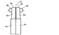
- FIG. 7 shows a state after cutting. In this state, that is, in a state where the heights of the front end surfaces 6e in the axial direction of the core 4 are substantially the same, the peeling portions 6d are butted against each other in the radial direction of the core 4. Laser welding by the welding system 2 is performed.
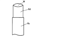
- 9A and 9B show an ideal shape after welding. It is desirable that the metal (here, copper) melted by the irradiation of the laser beam Lb is solidified into a smooth arc shape (including a hemispherical or dome-shaped concept) by surface tension. With such a welded shape W, the gripping member 26 after welding is smoothly pulled out, and cracks due to stress concentration are less likely to occur, so that the welded part is missing and the welded part is separated. And other problems can be suppressed.
- the metal here, copper
- laser light is not irradiated at the boundary between the pair of tip surfaces 6e shown in FIG. 7 where a gap is formed.
- laser welding can be performed without causing the laser light Lb to enter from the gap.
- the laser beam is irradiated with an irradiation pattern that is symmetric with respect to the boundary between the tip surfaces 6e. As a result, a smooth arc-shaped weld shape as shown in FIGS. 9A and 9B can be stably obtained.
- FIG. 1 is a plan view showing a state in which a pair of peeling portions 6d of the coil segment 6 shown in FIG. 6 are abutted side by side in the radial direction of the core 4, and reference numeral 28 denotes a pair of tip surfaces shown in FIG. The boundary between 6e is shown.
- the right rectangular front end surface in the figure is distinguished as 6eR
- the left rectangular front end surface is identified as 6eL.
- Reference numeral 6eC indicates one plane obtained by combining the tip surface 6eR and the tip surface 6eL.
- a rectangular preheating pattern 30 indicated by a one-dot chain line that goes around the outer periphery of the plane 6eC is a movement trajectory of the laser beam Lb, and continuously or in the vicinity of the outer periphery of one plane 6eC obtained by combining the tip surfaces 6eR and 6eL.
- An example of a first pattern that makes an intermittent circuit is shown.
- the X-shaped line corner elimination pattern 32 indicated by the alternate long and short dash line along the diagonal line of the plane 6eC shows an example of a continuous or intermittent pattern along the diagonal line of the plane 6eC, due to the movement locus of the laser light Lb. .
- the main welding pattern 34 of the rectangular line shown with the dashed-dotted line located inside the preheating pattern 30 is the 2nd pattern which circles the inside of the preheating pattern 30 continuously or intermittently by the movement locus of the laser beam Lb.
- the “movement trajectory” is a linear trajectory after the spot of the laser beam has moved, and the moving direction, moving order, moving speed, etc. of the laser beam do not matter.
- the laser beam Lb is irradiated and welded to the plane 6eC with the irradiation pattern including the above three patterns.
- the preheating pattern 30 is an irradiation pattern that continuously or intermittently makes a round around the outer periphery of the flat surface 6eC. “Continuous” means that the laser beam Lb is turned on to move, and “intermittent” means that the laser beam Lb is turned on and off repeatedly.
- the laser beam Lb moves straight to the left starting from the upper right corner of the plane 6eC (moving locus 30a), and moves straight across the boundary 28 to the upper left corner of the tip surface 6eL (moving locus 30b).
- the laser beam Lb is not irradiated when crossing the boundary 28. That is, the control device 10 turns off the irradiation of the laser beam Lb before the boundary 28 based on the movement distance on the tip surface 6eR calculated in advance, and the irradiation port of the laser head 18 enters the tip surface 6eL beyond the boundary 28. Immediately thereafter, control is performed to turn on the irradiation of the laser beam Lb.
- FIG. 1 the outline of the movement trajectory of each irradiation pattern is roughly shown for easy understanding, and irradiation OFF when crossing the boundary 28 is not reflected.
- the irradiation off period ⁇ t of the laser beam Lb is set corresponding to the maximum value of the gap formed randomly at the boundary 28 of each tip surface pair, and is obtained by experiment.
- the irradiation off period ⁇ t also varies depending on the moving speed of the laser light Lb.
- the laser beam Lb After the laser beam Lb travels straight to the upper left corner of the tip surface 6eL, it changes its direction by 90 ° and moves straight to the lower left corner of the tip surface 6eL (movement locus 30c). Thereafter, the direction is further changed by 90 ° to move straight (moving locus 30d), and move straight across the boundary 28 to the lower right corner of the tip surface 6eR (moving locus 30e). When crossing the boundary 28, the laser beam Lb is not irradiated as described above.
- control device 10 turns off the irradiation of the laser light Lb before the boundary 28 based on the movement distance on the tip surface 6eL calculated in advance, and the irradiation port of the laser head 18 enters the tip surface 6eR beyond the boundary 28. Immediately thereafter, control is performed to turn on the irradiation of the laser beam Lb. After the laser beam Lb moves straight to the lower right corner of the front end face 6eR, it changes its direction by 90 ° and moves straight to the start point (movement locus 30f).
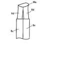
- the preheating pattern 30 is provided in order to define the outer shape of the weld shape so that the bulging portion Wa and the sag are not generated outside the flat surface 6eC (see FIG. 1) of the molten metal as shown in FIG. 9C. .
- it functions as a frame for restricting the random flow of the molten metal by the main welding described later.
- the movement trajectories 30a to 30f are formed by continuous irradiation of the laser light Lb in the respective ranges, but may be formed by intermittent irradiation.
- the starting point in the preheating pattern 30 is not limited to the above, and may be any part of the rectangular moving locus in FIG. 2A, and the moving direction is not limited.
- the corner eraser pattern 32 is an irradiation pattern that moves continuously along the diagonal line of the plane 6eC shown in FIG. 1, and the corner eraser pattern 32 has an outer corner portion Wb as shown in FIG. 9D. It is provided in order to prevent solidification in a state of protruding. Further, the corner eraser pattern 32 is also a pattern that contributes to the preheating of the flat surface 6 eC like the preheating pattern 30.
- the laser beam Lb moves straight diagonally downward to the left starting from the upper right corner of the plane 6eC (moving locus 32a), and moves linearly across the boundary 28 to the lower left corner of the tip surface 6eL. (Movement locus 32b).
- the laser beam Lb is not irradiated when crossing the boundary 28. That is, the control device 10 turns off the irradiation of the laser beam Lb before the boundary 28 based on the movement distance on the tip surface 6eR calculated in advance, and the irradiation port of the laser head 18 enters the tip surface 6eL beyond the boundary 28. Immediately thereafter, control is performed to turn on the irradiation of the laser beam Lb.
- the laser head 18 When the irradiation of the laser beam along one of the diagonal lines of the plane 6eC is completed, the laser head 18 is displaced in a state where the irradiation of the laser beam Lb is turned off. For example, the laser beam Lb obliquely upwards to the left starting from the lower right corner of the plane 6eC. Moves straight (moving locus 32c), and moves diagonally across the boundary 28 to the upper left corner of the tip surface 6eL (moving locus 32d).
- the laser beam Lb is not irradiated when crossing the boundary 28. That is, the control device 10 turns off the irradiation of the laser beam Lb before the boundary 28 based on the movement distance on the tip surface 6eR calculated in advance, and the irradiation port of the laser head 18 enters the tip surface 6eL beyond the boundary 28. Immediately thereafter, control is performed to turn on the irradiation of the laser beam Lb.
- the method for determining the irradiation off period of the laser beam Lb is the same as that in the case of the preheating pattern 30.
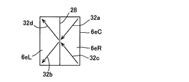
- the two starting points in the corner eraser pattern 32 are not limited to the above, and may exist on the tip surface 6eL side, or may exist on both the tip surface 6eR and the tip surface 6eL. Further, the moving direction is not limited. For example, as shown in FIG. 3, it is good also as an irradiation pattern which consists of the movement locus
- the laser beam Lb may move too much due to the inertia of the movement of the laser head 18, and the corner portion may be crushed and adversely affect the welded shape.
- the irradiation pattern By setting the irradiation pattern to be the central portion of the plane 6eC, the above concerns can be solved. In this case, since the laser beam Lb does not cross the boundary 28 in any movement, the problem that the laser beam Lb enters inward from the gap at the boundary 28 does not occur.
- the main welding pattern 34 is an irradiation pattern that continuously goes around the inside of the preheating pattern 30 in the plane 6eC shown in FIG.
- the laser beam Lb moves straight to the left starting from the upper right of the plane 6eC (movement locus 34a), and moves straight to the upper left of the plane 6eC across the boundary 28 (movement locus 34b).
- the laser beam Lb is not irradiated when crossing the boundary 28.
- control device 10 turns off the irradiation of the laser beam Lb before the boundary 28 based on the movement distance on the tip surface 6eR calculated in advance, and the irradiation port of the laser head 18 enters the tip surface 6eL beyond the boundary 28. Immediately thereafter, control is performed to turn on the irradiation of the laser beam Lb.
- the laser beam Lb After the laser beam Lb travels straight to the upper left of the plane 6eC, it changes its direction by 90 ° and moves straight to the lower left of the plane 6eC (movement locus 34c). After that, the direction is further changed by 90 ° to move straight (moving track 34d), and move straight across the boundary 28 to the lower right of the plane 6eC (moving track 34e).
- the control device 10 turns off the irradiation of the laser light Lb before the boundary 28 based on the movement distance on the tip surface 6eL calculated in advance, and the irradiation port of the laser head 18 enters the tip surface 6eR beyond the boundary 28. Immediately thereafter, control is performed to turn on the irradiation of the laser beam Lb.
- the method for determining the irradiation off period of the laser beam Lb is the same as that in the case of the preheating pattern 30.
- the laser beam Lb moves straight to the lower right of the plane 6eC, it changes its direction by 90 ° and moves straight to the start point (movement track 34f).
- the starting point in the main welding pattern 34 is not limited to the above, and may be any part of the rectangular movement locus in FIG. 2C, and the movement direction is not limited.
- the irradiation with the preheating pattern 30 is performed before the irradiation with the laser beam Lb by the main welding pattern 34, solidification proceeds in a state where the random flow of the molten metal by the main welding pattern 34 is regulated.
- the bulging portion Wa as shown in FIG. 1 does not occur, and the welding shape has a smooth arcuate contour due to surface tension.
- the corner portion Wb as shown in FIG. As described above, the corner blanking pattern 32 contributes to the preheating of the plane 6 eC together with the preheating pattern 30.
- the irradiation of the laser beam Lb based on the corner eraser pattern 32 is unnecessary depending on the conditions. For example, when four corners of a flat wire are chamfered to some extent in order to prevent damage to the insulating film, the degree of the corner shape remains small. It may be omitted. Further, in such a case, the preheating of the plane 6eC may be emphasized, and the laser beam Lb may be moved in an X shape within the range of the preheating pattern 30 shown in FIG. That is, an X-shaped irradiation pattern for moving the laser beam Lb along the diagonal line of the rectangular outline may be added to the preheating pattern 30.
- the control device 10 executes laser welding using the preheating pattern 30, the corner erase pattern 32, and the main welding pattern 34 based on a predetermined program.
- the predetermined program irradiates the laser beam Lb along the preheating pattern 30, irradiates the laser beam Lb along the square erase pattern 32, and irradiates the laser beam Lb along the main welding pattern 34.
- the steps are programmed to be executed in this order.
- the order of irradiating the laser beam Lb along the preheating pattern 30 and the step of irradiating the laser beam Lb along the corner elimination pattern 32 may be reversed.
- the nonvolatile memory (for example, ROM) of the control device 10 has welding conditions in which the area of the plane 6eC, which is the sum of the areas of the tip surfaces 6eR and 6eL, is divided in stages, and the laser in the laser oscillator 16 of the laser light irradiation device 8.
- a reference table (control table) 11 in which the relationship between the output and / or the moving speed of the laser head 18 is obtained in advance is stored.
- the ROM stores a laser beam off period ( ⁇ t) when crossing the boundary 28.
- ⁇ t laser beam off period
- the control device 10 selects the output and / or moving speed of the corresponding laser beam from the reference table 11 based on the input welding condition, and the condition of the laser beam irradiation device 8 is selected. Set up.
- the welding conditions to be input in addition to the area (cross-sectional area) of the flat surface 6eC, the vertical and horizontal dimensions of the tip surfaces 6eR and 6eL, the material of the coil segment 6, the temperature and humidity in the welding environment, and the level difference of the flat surface 6eC (boundary 28 ),
- the flatness of the flat surface 6eC, the surface properties of the flat surface 6eC (presence of oil or the like), the temperature of the coil segment 6, and the like are set in advance as sensory parameters in stages, and the operator judges and inputs them visually or by hand. Also good.
- the control device 10 receives input of welding conditions (S11), and uses the vertical and horizontal dimensions of the front end surfaces 6eR and 6eL in the input welding conditions, and in-plane these
- the moving direction and the moving distance of the laser beam Lb in FIG. 5 are calculated based on each irradiation pattern stored in advance in the control device 10 (S12), and the reference table is based on the area of the plane 6eC obtained from the vertical and horizontal dimensions.
- the output and moving speed of the laser beam Lb are determined (S13).
- each irradiation pattern includes information on the position.
- the control device 10 determines the timing for temporarily turning off the laser beam Lb based on the information on the crossing position and the above-described laser beam off period ⁇ t (S14). When the temperature difference or the humidity difference exceeds the reference range, the determined value is corrected using an appropriate correction coefficient. Based on the above determination, the control device 10 controls the laser beam irradiation device 8 (S15), irradiates the tip surfaces 6eR and 6eL of the coil segment 6 with the laser beam Lb, and welds the coil segment 6.
- the reference table 11 may be transmitted from a terminal device connected to the control device 10 by wire or wireless LAN, or may be acquired from an external storage device such as a USB memory.
- the single laser beam Lb is moved and irradiated so as to cross the boundary 28.
- the tip surfaces 6eR and 6eL are applied to the tip surfaces by one laser beam Lb without crossing the boundary 28. It is good also as a structure irradiated individually with the irradiation pattern which becomes substantially symmetrical with respect to the boundary between them. That is, half of each irradiation pattern shown in FIG. 1 (the preheating pattern 30, the corner erase pattern 32, and the main welding pattern 34) may be individually performed on the respective tip surfaces 6eR and 6eL.
- the laser beam irradiation pattern may be only the main welding pattern, and the shape thereof is not limited to a rectangular shape, but is symmetrical with respect to the boundary between the tip surfaces facing each other in the radial direction of the core among the tip portions of the coil segments. Any irradiation pattern may be used.
- the number of laser beams Lb irradiated on the plane 6eC is not limited to one.
- the laser beam Lb oscillated by the laser beam irradiation device 8 is branched by a beam splitter such as a half mirror, and the tip surfaces 6eR and 6eL are individually irradiated with substantially the same irradiation pattern with two laser beams Lb. It is good.
- DESCRIPTION OF SYMBOLS 2 ... Laser welding system, 4 ... Core, 4b ... End surface, 6 ... Coil segment, 6c ... Tip part, 6e ... Tip surface, 6eC ... Plane, 8 ... Laser beam irradiation apparatus, 10 ... Control apparatus, 11 ... Reference table, DESCRIPTION OF SYMBOLS 12 ... Input device, 30 ... Preheating pattern, 30a, 30b, 30c, 30d, 30e, 30f ... Movement locus, 32 ... Square eraser pattern, 32a, 32b, 32c, 32d ... Movement locus, 34 ... Main welding pattern, 34a , 34b, 34c, 34d, 34e, 34f ... movement locus, Lb ... laser light
Landscapes
- Engineering & Computer Science (AREA)
- Power Engineering (AREA)
- Physics & Mathematics (AREA)
- Optics & Photonics (AREA)
- Manufacturing & Machinery (AREA)
- Plasma & Fusion (AREA)
- Mechanical Engineering (AREA)
- Laser Beam Processing (AREA)
- Connections Effected By Soldering, Adhesion, Or Permanent Deformation (AREA)
- Manufacture Of Motors, Generators (AREA)
Abstract
コアのスロットに挿入されたU字状のコイルセグメントの隣り合う層の先端部(6c)同士が突き合わせられ、これらの先端面(6eR,6eL)は境界(28)を有する1つの平面(6eC)を形成している。この平面(6eC)に対してレーザ光(Lb)が照射され、溶接がなされる。レーザ光(Lb)の移動軌跡は、例えば境界(28)を横切る3つの照射パターンである、予熱パターン(30)、角消し用パターン(32)及び本溶接パターン(34)を備える。境界(28)を横切るときはレーザ光(Lb)の照射をオフするとよい。以上の構成により、レーザ光の入り込みによる問題を解消しつつ、レーザ溶接による高品位な溶接品質を得る。
Description
本発明は、モータや発電機等の回転電機又はトランス等の電磁機器に用いられるコイルを構成するコイルセグメントの端部同士を電気的に接合するためのレーザ溶接方法及びレーザ溶接システムに関する。
例えば、回転電機のステータでは、断面が矩形の平角線をU字状に折り曲げて形成した複数のコイルセグメントをコアのスロットに挿入し、コアの端面から突出したコイルセグメントの挿入方向先端部を周方向に層毎に逆向きに折り曲げ、隣り合う層で対向する先端部同士を電気的に接続することにより複数のコイルセグメントが一連に繋がったコイルを形成することが行われている。
コイルセグメントの挿入方向先端部は予め絶縁被膜を除去されており、絶縁被膜を除去された先端部同士は、その矩形状の先端面が1つの平面を形成するように横並びに突き合わされた状態で、TIG(Tungsten Inert Gas)溶接等のアーク溶接やYAG(Yttrium Aluminum Garnet)レーザ等のレーザ溶接により接合される。
コイルセグメントの挿入方向先端部は予め絶縁被膜を除去されており、絶縁被膜を除去された先端部同士は、その矩形状の先端面が1つの平面を形成するように横並びに突き合わされた状態で、TIG(Tungsten Inert Gas)溶接等のアーク溶接やYAG(Yttrium Aluminum Garnet)レーザ等のレーザ溶接により接合される。
アーク溶接では熱の影響を受ける範囲が広いため、溶接部以外の絶縁被膜の損傷を防止すべく絶縁被膜を除去する部分の長さを大きくとる必要があるが、この場合、コイルエンドの高さの増加を招来し、モータ等の小型化を阻害する要因となる。
これに対し、レーザ溶接では金属を局所的に溶融・凝固させることができて熱の影響範囲を狭くできるため、小型化や生産効率の向上、溶接品質の均一化への寄与が大きい。
これに対し、レーザ溶接では金属を局所的に溶融・凝固させることができて熱の影響範囲を狭くできるため、小型化や生産効率の向上、溶接品質の均一化への寄与が大きい。
しかしながら、レーザ溶接ではレーザ光の直進性による問題が存在する。この問題について以下に説明する。
コイルセグメントの先端部同士は、突き合わせ面の境界に隙間が生じないように把持部材(グリッパ)で加圧・挟持されるが、先端面の切断形状の不均一性等により完全に隙間が無くなることはむしろ少ない。換言すれば、隙間が無いように先端部同士を完全に密着させることは現実的に困難である。
コイルセグメントの先端部同士は、突き合わせ面の境界に隙間が生じないように把持部材(グリッパ)で加圧・挟持されるが、先端面の切断形状の不均一性等により完全に隙間が無くなることはむしろ少ない。換言すれば、隙間が無いように先端部同士を完全に密着させることは現実的に困難である。
一方、レーザ光は、2つの先端面へのエネルギー供給を均等にして溶融偏りを無くす観点から先端面に垂直な方向から境界を中心にして照射されるのが一般的である。
このため、僅かな隙間が存在した場合にはその隙間から内部にレーザ光が入り込み、絶縁被膜を破壊することがあった。
溶接部位の下方には、他層のコイルセグメントや他相のコイルセグメントが重なるように存在しているため、レーザ光の進入位置が深いとこれらの絶縁被膜を破壊し、層間絶縁又は相間絶縁が断たれる虞があった。
このため、僅かな隙間が存在した場合にはその隙間から内部にレーザ光が入り込み、絶縁被膜を破壊することがあった。
溶接部位の下方には、他層のコイルセグメントや他相のコイルセグメントが重なるように存在しているため、レーザ光の進入位置が深いとこれらの絶縁被膜を破壊し、層間絶縁又は相間絶縁が断たれる虞があった。
このようなレーザ光の直進性による弊害を防止すべく、特許文献1にはレーザ光を斜めに照射して接合する方法が提案されている。
この特許文献1で提案された導体接合方法は、その段落「0026」に記載されているように、裸導体の2つの対向面の一方に斜めに照射されたレーザ光により、その一方の対向面が局所的に溶融し、その熱で他方の対向面も溶融することにより、全体が溶融するというものである。
この斜め照射方式によれば、レーザ光が境界の隙間から内部に進入して絶縁被膜を破壊するという心配はない。
この特許文献1で提案された導体接合方法は、その段落「0026」に記載されているように、裸導体の2つの対向面の一方に斜めに照射されたレーザ光により、その一方の対向面が局所的に溶融し、その熱で他方の対向面も溶融することにより、全体が溶融するというものである。
この斜め照射方式によれば、レーザ光が境界の隙間から内部に進入して絶縁被膜を破壊するという心配はない。
ところで、この種のコイルセグメントの溶接対象となる端部の先端面は矩形(例えば長方形)の形状を有しており、溶接後の形状は左右対称の滑らかな半球状ないしドーム状に仕上がるのが望ましい。
滑らかでない部分や角部が存在すると経時的な振動等によりクラックが生じて溶着部が分離する起点となったり、溶接の肉盛りの一部が脱落してコア内に入り込み、短絡の原因となったりしやすいからである。
滑らかでない部分や角部が存在すると経時的な振動等によりクラックが生じて溶着部が分離する起点となったり、溶接の肉盛りの一部が脱落してコア内に入り込み、短絡の原因となったりしやすいからである。
このような問題を生じないレーザ溶接による形状を確実且つ均一に得るには、先端面同士を合わせた1つの平面に対する偏りの無い均一なエネルギー供給が必要となるが、上記のように先端面間の境界を中心にしてエネルギー供給の対称性(溶接形状の均一性)を得るべく照射すると、境界の隙間からレーザ光が入り込む問題を避けられなかった。
また、特許文献1の如く斜め照射方式を採用した場合、上記の左右対称の滑らかな溶接形状は期待できない。
また、特許文献1の如く斜め照射方式を採用した場合、上記の左右対称の滑らかな溶接形状は期待できない。
本発明は、このような現状に鑑みて創案されたもので、レーザ光の入り込みによる問題を解消しつつ、レーザ溶接による高品位な溶接品質を得ることができるようにすることを目的とする。
上記目的を達成するために、本発明のレーザ溶接方法は、コアの端面から突出したコイルセグメントの先端部のうち該コアの径方向で対向する先端部同士を、該先端部の矩形状の先端面の前記コアの軸方向における高さを略同じにして前記コアの径方向で突き合わせた状態で前記各先端面にレーザ光を照射して溶接するレーザ溶接方法であって、前記各先端面に対し、前記レーザ光を、前記各先端面間の境界に対して対称となる照射パターンで照射するものである。
このようなレーザ溶接方法において、前記各先端面に対して垂直にレーザ光を照射するとともに、前記各先端面間の境界を横切りながら前記レーザ光を移動させ、前記境界を横切るときは前記レーザ光の照射をオフするようにしてもよい。
また、前記照射パターンが、前記各先端面を合わせた一つの平面の外周近傍を連続的に又は断続的に一周する第1パターンと、該第1パターンの内側を連続的に又は断続的に一周する第2パターンとを含むようにしてもよい。
さらに、前記照射パターンが、前記各先端面を合わせた一つの平面の対角線に沿った連続的な又は断続的なパターンを含むようにしてもよい。
また、本発明のレーザ溶接システムは、コアの端面から突出したコイルセグメントの先端部のうち該コアの径方向で対向する先端部同士を、該各先端部の矩形状の先端面の前記コアの軸方向における高さを略同じにして前記コアの径方向で突き合わせた状態で前記各先端面にレーザ光を照射して溶接するレーザ溶接システムであって、レーザ光を照射するレーザ光照射装置と、前記レーザ光が、前記各先端面間の境界に対して対称となる照射パターンで前記各先端面を照射するように前記レーザ光照射装置を制御する制御装置とを有しているものである。
このようなレーザ溶接システムにおいて、前記制御装置は、前記各先端面に対して前記レーザ光が垂直に照射されて前記先端面間の境界を横切りながら移動するように、且つ前記レーザ光が前記境界を横切るときは前記レーザ光の照射をオフするように前記レーザ光照射装置を制御するようにしてもよい。
また、溶接条件を入力する入力装置と、前記先端面の面積を含む溶接条件と、前記レーザ光の出力及び/又は移動速度との関係が予め求められた参照テーブルとを有し、前記制御装置は、前記入力装置により入力された前記溶接条件に基づいて前記参照テーブルから対応する前記レーザ光の出力及び/又は移動速度を選択して前記レーザ光照射装置を制御するようにしてもよい。
本発明によれば、レーザ光の入り込みによる問題を解消しつつ、レーザ溶接による高品位な溶接品質を得ることができる。
以下、本発明の実施形態について図面を参照して説明する。
図4は、本発明の一実施形態に係るレーザ溶接システムの概要を示すブロック構成図である。
このレーザ溶接システム2は、コア4の端面4bから突出したコイルセグメントの先端部6cのうちコア4の径方向で対向する先端部6c同士を、該先端部6cの矩形状の先端面のコア4の軸方向における高さを略同じにしてコア4の径方向で突き合わせた状態でその各先端面にレーザ光を照射して溶接するレーザ溶接システムである。
そして、このレーザ溶接システム2は、レーザ光Lbを照射するレーザ光照射装置8と、レーザ光の移動軌跡が略同一の照射パターンで各先端面を照射するようにレーザ光照射装置8を制御する制御装置10と、溶接条件を入力するタッチパネル方式の入力装置12と、溶接対象の一対の先端部6c同士を加圧・挟持する後述のグリッパ機構と、溶接対象の一対の先端部6cの最先端を切断する切断機構23等を有している。
ここでは制御装置10と入力装置12とを分離して表示しているが、入力装置12が制御装置10に一体に設けられている構成でもよい。
このレーザ溶接システム2は、コア4の端面4bから突出したコイルセグメントの先端部6cのうちコア4の径方向で対向する先端部6c同士を、該先端部6cの矩形状の先端面のコア4の軸方向における高さを略同じにしてコア4の径方向で突き合わせた状態でその各先端面にレーザ光を照射して溶接するレーザ溶接システムである。
そして、このレーザ溶接システム2は、レーザ光Lbを照射するレーザ光照射装置8と、レーザ光の移動軌跡が略同一の照射パターンで各先端面を照射するようにレーザ光照射装置8を制御する制御装置10と、溶接条件を入力するタッチパネル方式の入力装置12と、溶接対象の一対の先端部6c同士を加圧・挟持する後述のグリッパ機構と、溶接対象の一対の先端部6cの最先端を切断する切断機構23等を有している。
ここでは制御装置10と入力装置12とを分離して表示しているが、入力装置12が制御装置10に一体に設けられている構成でもよい。
レーザ光照射装置8は、レーザ発振器16と、溶接対象に向けてレーザ光を垂直に射出するレーザヘッド18と、レーザ発振器16から発振されたレーザ光をレーザヘッド18に伝送する光ファイバ20と、レーザヘッド18を二次元変位させる駆動機構22等を有している。
レーザヘッド18は、光ファイバ20で伝送されるレーザ光を適切なスポット径に集光するための集光光学系(コリメートレンズや集光レンズ)を内蔵している。
レーザヘッド18は、光ファイバ20で伝送されるレーザ光を適切なスポット径に集光するための集光光学系(コリメートレンズや集光レンズ)を内蔵している。
制御装置10は、CPU(Central Processing Unit)、RAM(Random Access Memory)、ROM(Read Only Memory)、I/Oインターフェース等を有するマイクロコンピュータであり、レーザ発振器16の出力を制御したり、駆動機構22を介してレーザヘッド18の移動を制御する。
コア4はインデックス機構24に支持されており、溶接位置を変えるべくコア4の周方向に所定角度ずつ回転(インデックス回転)される。インデックス機構24によるインデックス回転は制御装置10により制御される。
溶接位置の位置変えは、レーザヘッド18の移動によって行ってもよい。
溶接位置の位置変えは、レーザヘッド18の移動によって行ってもよい。
コイルセグメントは図5に示すように、表面がエナメルやポリイミド樹脂等からなる絶縁被膜で覆われた平角線を曲げ加工によりU字状に形成したものである。具体的に説明すると、このコイルセグメント6は、直線状に延びる一対のスロット挿入部6a、6aと、これらを連結する連結部6bとからなり、連結部6bは段差形状(クランク形状)を有している。スロット挿入部6aの先端部6cの最先端は、溶接により電気的に接合するために絶縁被膜を除去されている。以下、この部分を剥離部6dと称する。
このコイルセグメント6は、図4に示すコア4の端面4a側から挿入され、スロット挿入部6aの先端部6cはコア4の端面4bから突出する。実際にはコア4の端面4aから連結部6bが突出しているが図4では省略している。
コア4の端面4bから突出したコイルセグメント6の先端部6cは、コア4の径方向に隣り合う層毎に、ツイスト加工によって周方向の異なる向きに折り曲げられる。
コア4の端面4bから突出したコイルセグメント6の先端部6cは、コア4の径方向に隣り合う層毎に、ツイスト加工によって周方向の異なる向きに折り曲げられる。
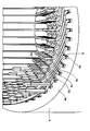
ツイスト加工後は、図6に示すように、隣り合う層の先端部6c同士が対向する。図6において、符号4cはコア4の周方向に放射状に複数配置されたスロットを、5はスロット4cに挿入された紙製又は合成樹脂製の絶縁シートを示している。
この状態で図7に示すように、剥離部6d同士がコア4の周方向の位置ずれを不図示の位置決め具で位置合わせされ、一対の把持部材26でコア4の径方向から加圧・挟持され、突き合わせられる。一対の把持部材26とこれらを駆動する不図示の駆動源とでグリッパ機構14が構成されている。
この状態で図7に示すように、剥離部6d同士がコア4の周方向の位置ずれを不図示の位置決め具で位置合わせされ、一対の把持部材26でコア4の径方向から加圧・挟持され、突き合わせられる。一対の把持部材26とこれらを駆動する不図示の駆動源とでグリッパ機構14が構成されている。
グリッパ機構14等による位置決めがなされた状態では、一対の剥離部6dの矩形状(長方形)の先端面6eの、コア4の軸方向における位置が揃っているとは限らない。実際には殆ど揃っていない。このため、溶接品質を向上させるべく、剥離部6d同士が把持された状態で先端面6eを揃えるための切断が切断機構23によってなされる。
図7は切断後の状態を示しており、この状態、即ちコア4の軸方向における先端面6eの高さを略同じにして剥離部6d同士をコア4の径方向で突き合わせた状態で、レーザ溶接システム2によるレーザ溶接が行われる。
図7は切断後の状態を示しており、この状態、即ちコア4の軸方向における先端面6eの高さを略同じにして剥離部6d同士をコア4の径方向で突き合わせた状態で、レーザ溶接システム2によるレーザ溶接が行われる。
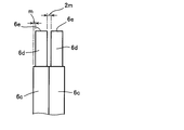
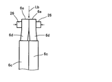
図8Aに示すように、コイルセグメント6の先端部6c同士を突き合わせた状態では、単純には絶縁被膜の厚みmの2倍分の隙間(2m)が剥離部6d間に存在する。この状態で図8Bに示すように把持部材26で加圧すると、条件によっては剥離部6d間の隙間は無くなりレーザ光Lbが剥離部6d間に進入することはない。
しかしながら、加圧によって剥離部6d間の隙間が無くなることは非常に稀で、実際には図8Cに示すように、切断後の先端面6eの形状の不均一性等により隙間が存在し、該隙間を介してレーザ光Lbが下方に進入する。
溶接部位の下方には、図6に示したように、他の層や相のコイルセグメントが重なるように存在するため、これらにレーザ光Lbが届いて絶縁被膜が破壊されると、層間又は相間の絶縁が断たれることになる。
溶接部位の下方には、図6に示したように、他の層や相のコイルセグメントが重なるように存在するため、これらにレーザ光Lbが届いて絶縁被膜が破壊されると、層間又は相間の絶縁が断たれることになる。
図9A及び図9Bは、溶接後の理想的な形状を示している。レーザ光Lbの照射によって溶融した金属(ここでは銅)が表面張力で滑らかな円弧状(半球状又はドーム状の概念を含む)に凝固するのが望ましい。
このような溶接形状Wとなれば、溶接後の把持部材26の引き抜きもスムーズになされるとともに、応力集中によるクラックが生じにくいので、溶接部の一部が欠けて溶着部が分離する起点となるなどの不具合を抑制することができる。
このような溶接形状Wとなれば、溶接後の把持部材26の引き抜きもスムーズになされるとともに、応力集中によるクラックが生じにくいので、溶接部の一部が欠けて溶着部が分離する起点となるなどの不具合を抑制することができる。
しかしながら、単にレーザ光を照射しても、図9Cに示すように、溶融金属が偏って凝固し、図7に示した一対の先端面6eを合わせた一つの平面の領域外に膨らむ膨らみ部Waが生じたり、図9Dに示すように、一つの平面の角部Wbが残って外側に突出した状態となったりする。
このような膨らみ部Waや角部Wbは、溶接後の把持部材26の引き抜きを阻害したり、把持部材26の引き抜きや経時的な振動で脱落して、コア4の内部に付着して短絡の原因になったりする虞がある。
このような膨らみ部Waや角部Wbは、溶接後の把持部材26の引き抜きを阻害したり、把持部材26の引き抜きや経時的な振動で脱落して、コア4の内部に付着して短絡の原因になったりする虞がある。
即ち、この種のレーザ溶接では、レーザ光Lbが剥離部6d間の隙間から進入して意図しない箇所で絶縁被膜が破壊される問題と、溶接形状の品質が一定しないという問題が併存している。
これらの問題を同時に解消する本発明の一実施形態のレーザ溶接方法を、図1及び図2を参照して説明する。
本実施形態において、隙間が形成される図7に示した一対の先端面6e間の境界では、レーザ光を照射しない。これにより、境界における隙間の有無に関係なく、隙間からのレーザ光Lbの入り込みを来すことなくレーザ溶接を行うことができる。また、各先端面6e間の境界に対して対称となる照射パターンでレーザ光の照射を行っている。このことにより、図9Aや図9Bに示したような滑らかな円弧状の溶接形状を安定して得ることができる。
本実施形態において、隙間が形成される図7に示した一対の先端面6e間の境界では、レーザ光を照射しない。これにより、境界における隙間の有無に関係なく、隙間からのレーザ光Lbの入り込みを来すことなくレーザ溶接を行うことができる。また、各先端面6e間の境界に対して対称となる照射パターンでレーザ光の照射を行っている。このことにより、図9Aや図9Bに示したような滑らかな円弧状の溶接形状を安定して得ることができる。
図1は、図6に示したコイルセグメント6の一対の剥離部6dがコア4の径方向で横並びに突き合わせられている状態の平面図であり、符号28は図7に示した一対の先端面6e間の境界を示している。ここでは、図中右側の長方形の先端面を6eR、左側の長方形の先端面を6eLとして区別する。符号6eCは先端面6eRと先端面6eLとを合わせた一つの平面を示している。
平面6eCの外周近傍を一周する一点鎖線で示す矩形ラインの予熱パターン30は、レーザ光Lbの移動軌跡であり、各先端面6eR、6eLを合わせた一つの平面6eCの外周近傍を連続的に又は断続的に一周する第1パターンの一例を示している。
平面6eCの対角線に沿う一点鎖線で示すX状ラインの角消し用パターン32は、レーザ光Lbの移動軌跡による、平面6eCの対角線に沿った連続的な又は断続的なパターンの一例を示している。
平面6eCの対角線に沿う一点鎖線で示すX状ラインの角消し用パターン32は、レーザ光Lbの移動軌跡による、平面6eCの対角線に沿った連続的な又は断続的なパターンの一例を示している。
また、予熱パターン30の内側に位置する一点鎖線で示す矩形ラインの本溶接パターン34は、レーザ光Lbの移動軌跡による、予熱パターン30の内側を連続的に又は断続的に一周する第2パターンの一例を示している。
上記「移動軌跡」とは、レーザ光のスポットが移動した後の線状の軌跡であり、レーザ光の移動方向や移動順序、移動速度などは問わない。
本実施形態では、平面6eCに対し、結果的に上記3つのパターンからなる照射パターンでレーザ光Lbを照射して溶接する。
上記「移動軌跡」とは、レーザ光のスポットが移動した後の線状の軌跡であり、レーザ光の移動方向や移動順序、移動速度などは問わない。
本実施形態では、平面6eCに対し、結果的に上記3つのパターンからなる照射パターンでレーザ光Lbを照射して溶接する。
図2Aを参照して、予熱パターン30におけるレーザ光Lbの移動軌跡を説明する。
予熱パターン30は、平面6eCの外周近傍を連続的又は断続的に一周する照射パターンである。連続的にとはレーザ光Lbの照射をオンにして移動することをいい、断続的にとはレーザ光Lbの照射のオン、オフを繰り返しながら移動することをいう。
予熱パターン30では、例えば平面6eCの右上隅を始点として左側へレーザ光Lbが直進移動し(移動軌跡30a)、境界28を横切って先端面6eLの左上隅まで直進移動する(移動軌跡30b)。
予熱パターン30は、平面6eCの外周近傍を連続的又は断続的に一周する照射パターンである。連続的にとはレーザ光Lbの照射をオンにして移動することをいい、断続的にとはレーザ光Lbの照射のオン、オフを繰り返しながら移動することをいう。
予熱パターン30では、例えば平面6eCの右上隅を始点として左側へレーザ光Lbが直進移動し(移動軌跡30a)、境界28を横切って先端面6eLの左上隅まで直進移動する(移動軌跡30b)。
ここで、境界28を横切るときはレーザ光Lbは照射されない。即ち、制御装置10は予め算出された先端面6eRにおける移動距離に基づいて境界28の手前でレーザ光Lbの照射をオフし、レーザヘッド18の照射口が境界28を越えて先端面6eLに入った直後にレーザ光Lbの照射をオンする制御を行う。なお、図1では各照射パターンの移動軌跡の全体輪郭を把握し易くするために大まかに示しており、境界28を横切るときの照射オフは反映していない。
レーザ光Lbの照射オフ期間Δtは、各先端面ペアの境界28でランダムに形成される隙間の最大値に対応して設定されており、実験により求められる。照射オフ期間Δtは、レーザ光Lbの移動速度によっても異なる。
レーザ光Lbの照射オフ期間Δtは、各先端面ペアの境界28でランダムに形成される隙間の最大値に対応して設定されており、実験により求められる。照射オフ期間Δtは、レーザ光Lbの移動速度によっても異なる。
レーザ光Lbは先端面6eLの左上隅まで直進した後は向きを90°変えて先端面6eLの左下隅まで直進移動する(移動軌跡30c)。その後、更に方向を90°変えて直進移動し(移動軌跡30d)、境界28を横切って先端面6eRの右下隅まで直進移動する(移動軌跡30e)。境界28を横切るときは上記と同様に、レーザ光Lbは照射されない。
即ち、制御装置10は予め算出された先端面6eLにおける移動距離に基づいて境界28の手前でレーザ光Lbの照射をオフし、レーザヘッド18の照射口が境界28を越えて先端面6eRに入った直後にレーザ光Lbの照射をオンする制御を行う。
レーザ光Lbが先端面6eRの右下隅まで直進移動した後は向きを90°変えて始点まで直進移動する(移動軌跡30f)。
レーザ光Lbが先端面6eRの右下隅まで直進移動した後は向きを90°変えて始点まで直進移動する(移動軌跡30f)。
予熱パターン30は、図9Cで示したような溶融金属の平面6eC(図1参照)外への膨らみ部Waや垂れ下がりが生じないように、溶接形状の外郭を規定するために設けられるものである。換言すれば、後述する本溶接による溶融金属のランダムな流動を規制する枠として機能するものである。
ここでは各移動軌跡30a~30fをそれぞれの範囲におけるレーザ光Lbの連続照射によって形成しているが、断続的な照射によって形成してもよい。
なお、予熱パターン30における始点は、上記に限定されず図2Aの矩形の移動軌跡のいずれの箇所でもよく、移動向きも限定されない。
ここでは各移動軌跡30a~30fをそれぞれの範囲におけるレーザ光Lbの連続照射によって形成しているが、断続的な照射によって形成してもよい。
なお、予熱パターン30における始点は、上記に限定されず図2Aの矩形の移動軌跡のいずれの箇所でもよく、移動向きも限定されない。
次に、図2Bを参照して、角消し用パターン32におけるレーザ光Lbの移動軌跡を説明する。
角消し用パターン32は、図1に示した平面6eCの対角線に沿って連続的に移動する照射パターンであり、角消し用パターン32は、図9Dで示したような角部Wbが残って外側に突出した状態で凝固することを防止するために設けられるものである。
また、角消し用パターン32は、予熱パターン30と同様に平面6eCの予熱にも寄与するパターンでもある。
角消し用パターン32では、例えば平面6eCの右上隅を始点として左斜め下方へレーザ光Lbが直進移動し(移動軌跡32a)、境界28を斜めに横切って先端面6eLの左下隅まで直進移動する(移動軌跡32b)。
角消し用パターン32は、図1に示した平面6eCの対角線に沿って連続的に移動する照射パターンであり、角消し用パターン32は、図9Dで示したような角部Wbが残って外側に突出した状態で凝固することを防止するために設けられるものである。
また、角消し用パターン32は、予熱パターン30と同様に平面6eCの予熱にも寄与するパターンでもある。
角消し用パターン32では、例えば平面6eCの右上隅を始点として左斜め下方へレーザ光Lbが直進移動し(移動軌跡32a)、境界28を斜めに横切って先端面6eLの左下隅まで直進移動する(移動軌跡32b)。
ここで、境界28を横切るときはレーザ光Lbは照射されない。即ち、制御装置10は予め算出された先端面6eRにおける移動距離に基づいて境界28の手前でレーザ光Lbの照射をオフし、レーザヘッド18の照射口が境界28を越えて先端面6eLに入った直後にレーザ光Lbの照射をオンする制御を行う。
平面6eCの対角線の一方に沿ったレーザ光の照射が完了すると、レーザ光Lbの照射をオフした状態でレーザヘッド18が変位し、例えば平面6eCの右下隅を始点として左斜め上方へレーザ光Lbが直進移動し(移動軌跡32c)、境界28を斜めに横切って先端面6eLの左上隅まで直進移動する(移動軌跡32d)。
ここで、境界28を横切るときはレーザ光Lbは照射されない。即ち、制御装置10は予め算出された先端面6eRにおける移動距離に基づいて境界28の手前でレーザ光Lbの照射をオフし、レーザヘッド18の照射口が境界28を越えて先端面6eLに入った直後にレーザ光Lbの照射をオンする制御を行う。いずれの場合も、レーザ光Lbの照射オフ期間の定め方は、予熱パターン30の場合と同様である。
なお、角消し用パターン32における2つの始点は上記に限定されず、先端面6eL側に存在してもよく、先端面6eRと先端面6eLの両方に存在してもよい。また、移動向きも限定されない。
例えば図3に示すように、平面6eCの4つの角部を始点として、それぞれ平面6eCの中心に向かって直進移動する移動軌跡32a、32b、32c、32dからなる照射パターンとしてもよい。
例えば図3に示すように、平面6eCの4つの角部を始点として、それぞれ平面6eCの中心に向かって直進移動する移動軌跡32a、32b、32c、32dからなる照射パターンとしてもよい。
平面6eCの角部が終点となる照射パターンでは、レーザヘッド18の移動の慣性によってレーザ光Lbが移動しすぎて角部が潰れて溶接形状に悪影響を及ぼす可能性があるが、いずれも終点が平面6eCの中央部となる照射パターンとすることにより、上記懸念を解消することができる。
この場合、レーザ光Lbはいずれの移動においても境界28を横切らないので、境界28での隙間からレーザ光Lbが内方に入り込む問題も生じない。
この場合、レーザ光Lbはいずれの移動においても境界28を横切らないので、境界28での隙間からレーザ光Lbが内方に入り込む問題も生じない。
次に、図2Cを参照して、本溶接パターン34におけるレーザ光Lbの移動軌跡を説明する。
本溶接パターン34は、図1に示した平面6eCにおける予熱パターン30の内方を連続的に一周する照射パターンである。本溶接パターン34では、例えば平面6eCの右上を始点として左側へレーザ光Lbが直進移動し(移動軌跡34a)、境界28を横切って平面6eCの左上まで直進移動する(移動軌跡34b)。
ここで、境界28を横切るときはレーザ光Lbは照射されない。即ち、制御装置10は予め算出された先端面6eRにおける移動距離に基づいて境界28の手前でレーザ光Lbの照射をオフし、レーザヘッド18の照射口が境界28を越えて先端面6eLに入った直後にレーザ光Lbの照射をオンする制御を行う。
本溶接パターン34は、図1に示した平面6eCにおける予熱パターン30の内方を連続的に一周する照射パターンである。本溶接パターン34では、例えば平面6eCの右上を始点として左側へレーザ光Lbが直進移動し(移動軌跡34a)、境界28を横切って平面6eCの左上まで直進移動する(移動軌跡34b)。
ここで、境界28を横切るときはレーザ光Lbは照射されない。即ち、制御装置10は予め算出された先端面6eRにおける移動距離に基づいて境界28の手前でレーザ光Lbの照射をオフし、レーザヘッド18の照射口が境界28を越えて先端面6eLに入った直後にレーザ光Lbの照射をオンする制御を行う。
レーザ光Lbは平面6eCの左上まで直進した後は向きを90°変えて平面6eCの左下まで直進移動する(移動軌跡34c)。その後、更に方向を90°変えて直進移動し(移動軌跡34d)、境界28を横切って平面6eCの右下まで直進移動する(移動軌跡34e)。境界28を横切るときは上記と同様に、レーザ光Lbは照射されない。
即ち、制御装置10は予め算出された先端面6eLにおける移動距離に基づいて境界28の手前でレーザ光Lbの照射をオフし、レーザヘッド18の照射口が境界28を越えて先端面6eRに入った直後にレーザ光Lbの照射をオンする制御を行う。いずれの場合も、レーザ光Lbの照射オフ期間の定め方は、予熱パターン30の場合と同様である。
即ち、制御装置10は予め算出された先端面6eLにおける移動距離に基づいて境界28の手前でレーザ光Lbの照射をオフし、レーザヘッド18の照射口が境界28を越えて先端面6eRに入った直後にレーザ光Lbの照射をオンする制御を行う。いずれの場合も、レーザ光Lbの照射オフ期間の定め方は、予熱パターン30の場合と同様である。
レーザ光Lbが平面6eCの右下まで直進移動した後は向きを90°変えて始点まで直進移動する(移動軌跡34f)。
なお、本溶接パターン34における始点は、上記に限定されず図2Cの矩形の移動軌跡のいずれの箇所でもよく、移動向きも限定されない。
なお、本溶接パターン34における始点は、上記に限定されず図2Cの矩形の移動軌跡のいずれの箇所でもよく、移動向きも限定されない。
実験の結果、以上の3つの溶接パターンを用いて溶接を行うことにより、図9A及び図9Bに示したような良好な溶接形状Wを得ることができた。
実験では、レーザ光照射装置8として、トルンプ社製のTruDisk4002(4000W;YAGレーザ)を使用した。平面6eCの面積は14.7mm2であった。
実験では、レーザ光照射装置8として、トルンプ社製のTruDisk4002(4000W;YAGレーザ)を使用した。平面6eCの面積は14.7mm2であった。
本溶接パターン34によるレーザ光Lbの照射の前に、予熱パターン30による照射を実施しているので、本溶接パターン34による溶融金属のランダムな流動が規制された状態で凝固が進行するので図9Cに示すような膨らみ部Waは生じず、表面張力による滑らかな円弧状の輪郭の溶接形状となる。また、角消し用パターン32により図9Dに示すような角部Wbも生じない。上記のように、角消し用パターン32は予熱パターン30とともに平面6eCの予熱にも寄与している。
予熱パターン30、角消し用パターン32及び本溶接パターン34のうち、条件によっては角消し用パターン32に基づくレーザ光Lbの照射は不要である。例えば、絶縁被膜の損傷を防止するために平角線の4つの角部がある程度面取りされている場合には、角部形状が残る度合いも少ないので、このような場合には角消し用パターン32を省略してもよい。
さらにこのような場合には、平面6eCの予熱に重きをおいて、図1に示す予熱パターン30の範囲内でレーザ光LbをX状に移動させて第2の予熱パターンとしてもよい。即ち、予熱パターン30に、矩形輪郭の対角線に沿ってレーザ光Lbを移動させるX状の照射パターンを追加してもよい。
さらにこのような場合には、平面6eCの予熱に重きをおいて、図1に示す予熱パターン30の範囲内でレーザ光LbをX状に移動させて第2の予熱パターンとしてもよい。即ち、予熱パターン30に、矩形輪郭の対角線に沿ってレーザ光Lbを移動させるX状の照射パターンを追加してもよい。
制御装置10は、所定のプログラムに基づいて、予熱パターン30、角消し用パターン32及び本溶接パターン34によるレーザ溶接を実行する。
所定のプログラムは、予熱パターン30に沿ってレーザ光Lbを照射するステップと、角消し用パターン32に沿ってレーザ光Lbを照射するステップと、本溶接パターン34に沿ってレーザ光Lbを照射するステップとをこの順に実行させるようにプログラミングされている。
予熱パターン30に沿ってレーザ光Lbを照射するステップと、角消し用パターン32に沿ってレーザ光Lbを照射するステップとは順序を逆にしてもよい。
所定のプログラムは、予熱パターン30に沿ってレーザ光Lbを照射するステップと、角消し用パターン32に沿ってレーザ光Lbを照射するステップと、本溶接パターン34に沿ってレーザ光Lbを照射するステップとをこの順に実行させるようにプログラミングされている。
予熱パターン30に沿ってレーザ光Lbを照射するステップと、角消し用パターン32に沿ってレーザ光Lbを照射するステップとは順序を逆にしてもよい。
制御装置10の不揮発性メモリ(例えばROM)には、先端面6eR、6eLの面積を合わせた平面6eCの面積が段階的に区画された溶接条件と、レーザ光照射装置8のレーザ発振器16におけるレーザ出力及び/又はレーザヘッド18の移動速度との関係が予め求められた参照テーブル(制御テーブル)11が格納されている。また、ROMには境界28を横切るときのレーザ光オフ期間(Δt)が記憶されている。図4では分かり易くするため、制御装置10の外に参照テーブル11を示している。
入力装置12により溶接条件が入力されると、制御装置10は入力された溶接条件に基づいて参照テーブル11から対応するレーザ光の出力及び/又は移動速度を選択してレーザ光照射装置8の条件設定を行う。
入力装置12により溶接条件が入力されると、制御装置10は入力された溶接条件に基づいて参照テーブル11から対応するレーザ光の出力及び/又は移動速度を選択してレーザ光照射装置8の条件設定を行う。
入力する溶接条件としては、平面6eCの面積(断面積)の他に、先端面6eR、6eLの縦及び横寸法、コイルセグメント6の材質、溶接環境における温度、湿度、平面6eCの段差(境界28における段差)、平面6eCの平面度、平面6eCの表面性状(油等の有無)、コイルセグメント6の温度等がある。
平面6eCの段差、平面6eCの平面度、平面6eCの表面性状、コイルセグメント6の温度は、予め官能パラメータとしてレベルを段階的に設定し、オペレータが目視や手触りで判断して入力するようにしてもよい。
平面6eCの段差、平面6eCの平面度、平面6eCの表面性状、コイルセグメント6の温度は、予め官能パラメータとしてレベルを段階的に設定し、オペレータが目視や手触りで判断して入力するようにしてもよい。
例えば、制御装置10は、図10に示すように、溶接条件の入力を受け付け(S11)、その入力された溶接条件中の先端面6eR、6eLの縦及び横寸法を用いて、これらの面内でのレーザ光Lbの移動方向及び移動距離を、予め制御装置10に記憶された各照射パターンに基づいて算出するとともに(S12)、縦及び横寸法から求めた平面6eCの面積に基づいて参照テーブル11を参照し、レーザ光Lbの出力及び移動速度を決定する(S13)。ここで、各照射パターンには、パターンが先端面間の境界28を横切る場合、その位置の情報も含まれる。制御装置10は、その横切る位置の情報と、上述のレーザ光オフ期間Δtとに基づき、レーザ光Lbを一時的にオフするタイミングを決定する(S14)。温度差や湿度差が基準範囲を超えている場合には適宜の補正係数を用いて決定値を補正する。
制御装置10は、以上の決定に基づきレーザ光照射装置8を制御し(S15)、コイルセグメント6の先端面6eR、6eLにレーザ光Lbを照射して、コイルセグメント6を溶接する。
制御装置10は、以上の決定に基づきレーザ光照射装置8を制御し(S15)、コイルセグメント6の先端面6eR、6eLにレーザ光Lbを照射して、コイルセグメント6を溶接する。
参照テーブル11は、制御装置10に有線や無線LANで接続された端末機器から送信するようにしてもよく、又はUSBメモリ等の外部記憶装置から取得するようにしてもよい。
上記実施形態では、1つのレーザ光Lbを境界28を横切るように移動させて照射する構成としたが、境界28を横切ることなく1つのレーザ光Lbで各先端面6eR、6eLをその各先端面間の境界に対して略対称となる照射パターンで個別に照射する構成としてもよい。即ち、図1に示した各照射パターン(予熱パターン30、角消し用パターン32、本溶接パターン34)の半分をそれぞれ各先端面6eR、6eLに対して個別に実施してもよい。
また、レーザ光の照射パターンは、本溶接パターンだけでもよく、その形状も矩形に限らず、コイルセグメントの先端部のうちコアの径方向で対向する各先端面間の境界に対して対称となる照射パターンであればよい。
さらに、平面6eCに照射するレーザ光Lbは1本に限定されない。例えば、レーザ光照射装置8で発振されたレーザ光Lbを、ハーフミラー等のビームスプリッタで分岐し、2本のレーザ光Lbで先端面6eR、6eLを略同一の照射パターンにより個別に照射する構成としてもよい。
さらに、平面6eCに照射するレーザ光Lbは1本に限定されない。例えば、レーザ光照射装置8で発振されたレーザ光Lbを、ハーフミラー等のビームスプリッタで分岐し、2本のレーザ光Lbで先端面6eR、6eLを略同一の照射パターンにより個別に照射する構成としてもよい。
以上、本発明の好ましい実施形態について説明したが、本発明はかかる特定の実施形態に限定されるものではなく、種々の変形・変更が可能である。上述した本発明の構成は、一部のみ取り出して実施することもできるし、以上の説明の中で述べた変形は、相互に矛盾しない限り任意に組み合わせて適用可能である。本発明の実施形態に記載された効果は、本発明から生じる最も好適な効果を例示したに過ぎず、本発明による効果は、本発明の実施形態に記載されたものに限定されるものではない。
2…レーザ溶接システム、4…コア、4b…端面、6…コイルセグメント、6c…先端部、6e…先端面、6eC…平面、8…レーザ光照射装置、10…制御装置、11…参照テーブル、12…入力装置、30…予熱パターン、30a,30b,30c,30d,30e,30f…移動軌跡、32…角消し用パターン、32a,32b,32c,32d…移動軌跡、34…本溶接パターン、34a,34b,34c,34d,34e,34f…移動軌跡、Lb…レーザ光
Claims (7)
- コアの端面から突出したコイルセグメントの先端部のうち該コアの径方向で対向する先端部同士を、該各先端部の矩形状の先端面の前記コアの軸方向における高さを略同じにして前記コアの径方向で突き合わせた状態で前記各先端面にレーザ光を照射して溶接するレーザ溶接方法であって、
前記各先端面に対し、前記レーザ光を、前記各先端面間の境界に対して対称となる照射パターンで照射することを特徴とするレーザ溶接方法。 - 請求項1に記載のレーザ溶接方法において、
前記各先端面に対して垂直にレーザ光を照射するとともに、前記各先端面間の境界を横切りながら前記レーザ光を移動させ、前記境界を横切るときは前記レーザ光の照射をオフすることを特徴とするレーザ溶接方法。 - 請求項1又は2に記載のレーザ溶接方法において、
前記照射パターンが、前記各先端面を合わせた一つの平面の外周近傍を連続的に又は断続的に一周する第1パターンと、該第1パターンの内側を連続的に又は断続的に一周する第2パターンとを含むことを特徴とするレーザ溶接方法。 - 請求項1乃至3のいずれか一項に記載のレーザ溶接方法において、
前記照射パターンが、前記各先端面を合わせた一つの平面の対角線に沿った連続的又は断続的なパターンを含むことを特徴とするレーザ溶接方法。 - コアの端面から突出したコイルセグメントの先端部のうち該コアの径方向で対向する先端部同士を、該各先端部の矩形状の先端面の前記コアの軸方向における高さを略同じにして前記コアの径方向で突き合わせた状態で前記各先端面にレーザ光を照射して溶接するレーザ溶接システムであって、
レーザ光を照射するレーザ光照射装置と、前記レーザ光が、前記各先端面間の境界に対して対称となる照射パターンで前記各先端面を照射するように前記レーザ光照射装置を制御する制御装置とを有していることを特徴とするレーザ溶接システム。 - 請求項5に記載のレーザ溶接システムにおいて、
前記制御装置は、前記各先端面に対して前記レーザ光が垂直に照射されて前記先端面間の境界を横切りながら移動するように、且つ前記レーザ光が前記境界を横切るときは前記レーザ光の照射をオフするように前記レーザ光照射装置を制御することを特徴とするレーザ溶接システム。 - 請求項5又は6に記載のレーザ溶接システムにおいて、
溶接条件を入力する入力装置と、
前記先端面の面積を含む溶接条件と、前記レーザ光の出力及び/又は移動速度との関係が予め求められた参照テーブルと、
を有し、
前記制御装置は、前記入力装置により入力された前記溶接条件に基づいて前記参照テーブルから対応する前記レーザ光の出力及び/又は移動速度を選択して前記レーザ光照射装置を制御することを特徴とするレーザ溶接システム。
Priority Applications (1)
| Application Number | Priority Date | Filing Date | Title |
|---|---|---|---|
| JP2020500400A JP7054265B2 (ja) | 2018-02-19 | 2019-02-04 | レーザ溶接方法及びレーザ溶接システム |
Applications Claiming Priority (2)
| Application Number | Priority Date | Filing Date | Title |
|---|---|---|---|
| JP2018027421 | 2018-02-19 | ||
| JP2018-027421 | 2018-02-19 |
Publications (1)
| Publication Number | Publication Date |
|---|---|
| WO2019159737A1 true WO2019159737A1 (ja) | 2019-08-22 |
Family
ID=67619859
Family Applications (1)
| Application Number | Title | Priority Date | Filing Date |
|---|---|---|---|
| PCT/JP2019/003832 Ceased WO2019159737A1 (ja) | 2018-02-19 | 2019-02-04 | レーザ溶接方法及びレーザ溶接システム |
Country Status (2)
| Country | Link |
|---|---|
| JP (1) | JP7054265B2 (ja) |
| WO (1) | WO2019159737A1 (ja) |
Cited By (22)
| Publication number | Priority date | Publication date | Assignee | Title |
|---|---|---|---|---|
| JPWO2021100457A1 (ja) * | 2019-11-20 | 2021-05-27 | ||
| JP2021093832A (ja) * | 2019-12-10 | 2021-06-17 | 日立Astemo株式会社 | コイル及びコイルの製造方法 |
| WO2021182634A1 (ja) * | 2020-03-12 | 2021-09-16 | アイシン・エィ・ダブリュ株式会社 | 回転電機用ステータ製造方法 |
| JPWO2021182636A1 (ja) * | 2020-03-12 | 2021-09-16 | ||
| JP2021145473A (ja) * | 2020-03-12 | 2021-09-24 | 株式会社アイシン | 回転電機用ステータ製造方法 |
| WO2022211133A1 (ja) * | 2021-04-02 | 2022-10-06 | 古河電気工業株式会社 | レーザ溶接方法およびレーザ溶接装置 |
| CN115383303A (zh) * | 2022-09-01 | 2022-11-25 | 深圳泰德激光技术股份有限公司 | 铜线焊接方法、设备及计算机可读存储介质 |
| JP2022177664A (ja) * | 2021-05-18 | 2022-12-01 | トヨタ自動車株式会社 | レーザ溶接方法 |
| JP2022182279A (ja) * | 2021-05-28 | 2022-12-08 | 古河電気工業株式会社 | レーザ溶接方法、レーザ溶接装置、および電気装置 |
| JPWO2023281930A1 (ja) * | 2021-07-08 | 2023-01-12 | ||
| US20230026208A1 (en) * | 2021-07-26 | 2023-01-26 | Denso Corporation | Stator and method of manufacturing same |
| US20230040799A1 (en) * | 2021-08-03 | 2023-02-09 | Denso Corporation | Stator and method for producing stator |
| EP4160875A1 (de) | 2021-10-01 | 2023-04-05 | Valeo eAutomotive Germany GmbH | Formleiter für eine wicklung eines aktivteils einer rotierenden elektrischen maschine, aktivteil für eine rotierende elektrische maschine und zugehöriges herstellungsverfahren |
| EP4160874A1 (de) | 2021-10-01 | 2023-04-05 | Valeo eAutomotive Germany GmbH | Verfahren zur herstellung eines aktivteils für eine rotierende elektrische maschine, aktivteil für eine rotierende elektrische maschine und rotierende elektrische maschine |
| EP4159358A1 (de) | 2021-10-01 | 2023-04-05 | Valeo eAutomotive Germany GmbH | Verfahren zur herstellung eines aktivteils für eine rotierende elektrische maschine, aktivteil für eine rotierende elektrische maschine und rotierende elektrische maschine |
| JP2023537399A (ja) * | 2020-08-14 | 2023-08-31 | コアレイズ オーワイ | 時間依存走査パターンおよびエネルギー入力を用いた金属ピン対のレーザ溶接 |
| JPWO2023175724A1 (ja) * | 2022-03-15 | 2023-09-21 | ||
| CN116833563A (zh) * | 2023-07-21 | 2023-10-03 | 联合汽车电子有限公司 | 一种扁线电机定子焊接工艺 |
| WO2024029530A1 (ja) | 2022-08-03 | 2024-02-08 | 古河電気工業株式会社 | コイルの溶接装置及び溶接方法 |
| JP2024019291A (ja) * | 2020-10-20 | 2024-02-08 | 古河電気工業株式会社 | レーザ溶接方法 |
| JP2025124143A (ja) * | 2024-02-14 | 2025-08-26 | 本田技研工業株式会社 | 導体接合方法 |
| WO2025210992A1 (ja) * | 2024-04-01 | 2025-10-09 | 三菱電機株式会社 | 回転電機および回転電機の製造方法 |
Families Citing this family (1)
| Publication number | Priority date | Publication date | Assignee | Title |
|---|---|---|---|---|
| GB2639192A (en) * | 2024-03-07 | 2025-09-17 | Jaguar Land Rover Ltd | Laser welding method |
Citations (3)
| Publication number | Priority date | Publication date | Assignee | Title |
|---|---|---|---|---|
| JPH06210476A (ja) * | 1993-01-14 | 1994-08-02 | Shibuya Kogyo Co Ltd | レーザ加工装置 |
| JP2014205166A (ja) * | 2013-04-12 | 2014-10-30 | 日本車輌製造株式会社 | レーザ溶接方法およびレーザ・アークハイブリッド溶接方法 |
| JP2018020340A (ja) * | 2016-08-02 | 2018-02-08 | トヨタ自動車株式会社 | 平角線のレーザ溶接方法 |
-
2019
- 2019-02-04 JP JP2020500400A patent/JP7054265B2/ja active Active
- 2019-02-04 WO PCT/JP2019/003832 patent/WO2019159737A1/ja not_active Ceased
Patent Citations (3)
| Publication number | Priority date | Publication date | Assignee | Title |
|---|---|---|---|---|
| JPH06210476A (ja) * | 1993-01-14 | 1994-08-02 | Shibuya Kogyo Co Ltd | レーザ加工装置 |
| JP2014205166A (ja) * | 2013-04-12 | 2014-10-30 | 日本車輌製造株式会社 | レーザ溶接方法およびレーザ・アークハイブリッド溶接方法 |
| JP2018020340A (ja) * | 2016-08-02 | 2018-02-08 | トヨタ自動車株式会社 | 平角線のレーザ溶接方法 |
Cited By (45)
| Publication number | Priority date | Publication date | Assignee | Title |
|---|---|---|---|---|
| JPWO2021100457A1 (ja) * | 2019-11-20 | 2021-05-27 | ||
| JP7514255B2 (ja) | 2019-11-20 | 2024-07-10 | 日立Astemo株式会社 | 回転電機の固定子の製造方法、回転電機の固定子、及び回転電機 |
| JP7193442B2 (ja) | 2019-12-10 | 2022-12-20 | 日立Astemo株式会社 | コイル及びコイルの製造方法 |
| JP2021093832A (ja) * | 2019-12-10 | 2021-06-17 | 日立Astemo株式会社 | コイル及びコイルの製造方法 |
| JP2021145476A (ja) * | 2020-03-12 | 2021-09-24 | 株式会社アイシン | 回転電機用ステータ製造方法 |
| JP2021145473A (ja) * | 2020-03-12 | 2021-09-24 | 株式会社アイシン | 回転電機用ステータ製造方法 |
| WO2021182636A1 (ja) * | 2020-03-12 | 2021-09-16 | アイシン・エィ・ダブリュ株式会社 | 回転電機用ステータ製造方法 |
| CN115136474A (zh) * | 2020-03-12 | 2022-09-30 | 株式会社爱信 | 旋转电机用定子制造方法 |
| JPWO2021182636A1 (ja) * | 2020-03-12 | 2021-09-16 | ||
| JP7460403B2 (ja) | 2020-03-12 | 2024-04-02 | 株式会社アイシン | 回転電機用ステータ製造方法 |
| JP7335420B2 (ja) | 2020-03-12 | 2023-08-29 | 株式会社アイシン | 回転電機用ステータ製造方法 |
| WO2021182634A1 (ja) * | 2020-03-12 | 2021-09-16 | アイシン・エィ・ダブリュ株式会社 | 回転電機用ステータ製造方法 |
| JP7222945B2 (ja) | 2020-03-12 | 2023-02-15 | 株式会社アイシン | 回転電機用ステータ製造方法 |
| JP2023537399A (ja) * | 2020-08-14 | 2023-08-31 | コアレイズ オーワイ | 時間依存走査パターンおよびエネルギー入力を用いた金属ピン対のレーザ溶接 |
| JP7662768B2 (ja) | 2020-08-14 | 2025-04-15 | コアレイズ オーワイ | 時間依存走査パターンおよびエネルギー入力を用いた金属ピン対のレーザ溶接 |
| US12330235B2 (en) | 2020-08-14 | 2025-06-17 | Corelase Oy | Laser welding of metal pin pairs with time-dependent scan pattern and energy input |
| JP7733087B2 (ja) | 2020-10-20 | 2025-09-02 | 古河電気工業株式会社 | レーザ溶接方法 |
| JP2024019291A (ja) * | 2020-10-20 | 2024-02-08 | 古河電気工業株式会社 | レーザ溶接方法 |
| JP7585464B2 (ja) | 2021-04-02 | 2024-11-18 | 古河電気工業株式会社 | レーザ溶接方法およびレーザ溶接装置 |
| JP2024169684A (ja) * | 2021-04-02 | 2024-12-05 | 古河電気工業株式会社 | レーザ溶接方法およびレーザ溶接装置 |
| JPWO2022211133A1 (ja) * | 2021-04-02 | 2022-10-06 | ||
| WO2022211133A1 (ja) * | 2021-04-02 | 2022-10-06 | 古河電気工業株式会社 | レーザ溶接方法およびレーザ溶接装置 |
| JP2022177664A (ja) * | 2021-05-18 | 2022-12-01 | トヨタ自動車株式会社 | レーザ溶接方法 |
| JP7512950B2 (ja) | 2021-05-18 | 2024-07-09 | トヨタ自動車株式会社 | レーザ溶接方法 |
| JP2022182279A (ja) * | 2021-05-28 | 2022-12-08 | 古河電気工業株式会社 | レーザ溶接方法、レーザ溶接装置、および電気装置 |
| JP7665419B2 (ja) | 2021-05-28 | 2025-04-21 | 古河電気工業株式会社 | レーザ溶接方法 |
| WO2023281930A1 (ja) * | 2021-07-08 | 2023-01-12 | パナソニックIpマネジメント株式会社 | レーザ溶接装置、レーザ溶接方法及び回転電機の製造方法 |
| JPWO2023281930A1 (ja) * | 2021-07-08 | 2023-01-12 | ||
| US20230026208A1 (en) * | 2021-07-26 | 2023-01-26 | Denso Corporation | Stator and method of manufacturing same |
| US12463486B2 (en) * | 2021-07-26 | 2025-11-04 | Denso Corporation | Stator with coat-removed portions of electrical conductor wires and method of manufacturing same |
| US20230040799A1 (en) * | 2021-08-03 | 2023-02-09 | Denso Corporation | Stator and method for producing stator |
| EP4159358A1 (de) | 2021-10-01 | 2023-04-05 | Valeo eAutomotive Germany GmbH | Verfahren zur herstellung eines aktivteils für eine rotierende elektrische maschine, aktivteil für eine rotierende elektrische maschine und rotierende elektrische maschine |
| EP4160874A1 (de) | 2021-10-01 | 2023-04-05 | Valeo eAutomotive Germany GmbH | Verfahren zur herstellung eines aktivteils für eine rotierende elektrische maschine, aktivteil für eine rotierende elektrische maschine und rotierende elektrische maschine |
| EP4160875A1 (de) | 2021-10-01 | 2023-04-05 | Valeo eAutomotive Germany GmbH | Formleiter für eine wicklung eines aktivteils einer rotierenden elektrischen maschine, aktivteil für eine rotierende elektrische maschine und zugehöriges herstellungsverfahren |
| WO2023052471A1 (de) | 2021-10-01 | 2023-04-06 | Valeo Eautomotive Germany Gmbh | Formleiter für eine wicklung eines aktivteils einer rotierenden elektrischen maschine, aktivteil für eine rotierende elektrische maschine und zugehöriges herstellungsverfahren |
| JP7791306B2 (ja) | 2022-03-15 | 2025-12-23 | 株式会社東芝 | レーザ溶接方法、および回転電機の製造方法 |
| DE112022006862T5 (de) | 2022-03-15 | 2025-01-09 | Kabushiki Kaisha Toshiba | Laserschweissverfahren und verfahren zur herstellung einer rotierenden elektrischen maschine |
| JPWO2023175724A1 (ja) * | 2022-03-15 | 2023-09-21 | ||
| KR20250041168A (ko) | 2022-08-03 | 2025-03-25 | 후루카와 덴키 고교 가부시키가이샤 | 코일의 용접 장치 및 용접 방법 |
| WO2024029530A1 (ja) | 2022-08-03 | 2024-02-08 | 古河電気工業株式会社 | コイルの溶接装置及び溶接方法 |
| CN115383303A (zh) * | 2022-09-01 | 2022-11-25 | 深圳泰德激光技术股份有限公司 | 铜线焊接方法、设备及计算机可读存储介质 |
| CN116833563A (zh) * | 2023-07-21 | 2023-10-03 | 联合汽车电子有限公司 | 一种扁线电机定子焊接工艺 |
| JP2025124143A (ja) * | 2024-02-14 | 2025-08-26 | 本田技研工業株式会社 | 導体接合方法 |
| JP7844522B2 (ja) | 2024-02-14 | 2026-04-13 | 本田技研工業株式会社 | 導体接合方法 |
| WO2025210992A1 (ja) * | 2024-04-01 | 2025-10-09 | 三菱電機株式会社 | 回転電機および回転電機の製造方法 |
Also Published As
| Publication number | Publication date |
|---|---|
| JPWO2019159737A1 (ja) | 2021-02-25 |
| JP7054265B2 (ja) | 2022-04-13 |
Similar Documents
| Publication | Publication Date | Title |
|---|---|---|
| WO2019159737A1 (ja) | レーザ溶接方法及びレーザ溶接システム | |
| JP6390672B2 (ja) | 平角線のレーザ溶接方法 | |
| JP6593280B2 (ja) | 平角線のレーザ溶接方法 | |
| JP5958109B2 (ja) | 回転電機の導体接合方法 | |
| JP7063693B2 (ja) | 平角線のレーザ溶接方法 | |
| JP7733087B2 (ja) | レーザ溶接方法 | |
| JP6299136B2 (ja) | 鋼板のレーザー溶接方法およびレーザー溶接装置 | |
| US12390881B2 (en) | Laser welding method | |
| JP2014183623A (ja) | 回転電機の導体接合方法及び回転電機のコイル | |
| CN116568450A (zh) | 用于激光焊接导电线的方法和装置 | |
| WO2020170413A1 (ja) | 銅を含む部材の溶接方法、および回転電機の製造方法 | |
| JP2013109948A (ja) | 角線の接合構造及び接合方法 | |
| JP2025100655A (ja) | レーザ溶接方法およびレーザ溶接装置 | |
| JP2018121396A (ja) | コイルの製造方法 | |
| JP2021044890A (ja) | 導線の接合方法 | |
| JP2023128200A (ja) | 溶接方法およびレーザ装置 | |
| JP2021129341A (ja) | 積層鉄心の製造方法 | |
| JP2021044883A (ja) | 導線の接合方法 | |
| JP2023059864A (ja) | レーザ溶接方法およびレーザ溶接装置 | |
| US20260108986A1 (en) | Laser welding method and method for manufacturing rotary electrical machine | |
| CN111774728B (zh) | 定子铜线焊接方法及控制器、激光加工机和可读程序载体 | |
| JP2024127301A (ja) | 電線接続端子の製造方法、電線接続端子、および端子付き電線 | |
| JPS6355877A (ja) | シ−トコイルの接続方法 | |
| JP2022115294A (ja) | レーザ溶接方法、レーザ溶接装置、および溶接体 | |
| JP3190864U (ja) | アーク溶接用エンドタブ |
Legal Events
| Date | Code | Title | Description |
|---|---|---|---|
| 121 | Ep: the epo has been informed by wipo that ep was designated in this application |
Ref document number: 19754627 Country of ref document: EP Kind code of ref document: A1 |
|
| ENP | Entry into the national phase |
Ref document number: 2020500400 Country of ref document: JP Kind code of ref document: A |
|
| NENP | Non-entry into the national phase |
Ref country code: DE |
|
| 122 | Ep: pct application non-entry in european phase |
Ref document number: 19754627 Country of ref document: EP Kind code of ref document: A1 |