WO2019163280A1 - Tour - Google Patents
Tour Download PDFInfo
- Publication number
- WO2019163280A1 WO2019163280A1 PCT/JP2018/047194 JP2018047194W WO2019163280A1 WO 2019163280 A1 WO2019163280 A1 WO 2019163280A1 JP 2018047194 W JP2018047194 W JP 2018047194W WO 2019163280 A1 WO2019163280 A1 WO 2019163280A1
- Authority
- WO
- WIPO (PCT)
- Prior art keywords
- tool
- spindle
- axis direction
- tool post
- tools
- Prior art date
- Legal status (The legal status is an assumption and is not a legal conclusion. Google has not performed a legal analysis and makes no representation as to the accuracy of the status listed.)
- Ceased
Links
Images




Classifications
-
- B—PERFORMING OPERATIONS; TRANSPORTING
- B23—MACHINE TOOLS; METAL-WORKING NOT OTHERWISE PROVIDED FOR
- B23B—TURNING; BORING
- B23B3/00—General-purpose turning-machines or devices, e.g. centre lathes with feed rod and lead screw; Sets of turning-machines
- B23B3/30—Turning-machines with two or more working-spindles, e.g. in fixed arrangement
-
- B—PERFORMING OPERATIONS; TRANSPORTING
- B23—MACHINE TOOLS; METAL-WORKING NOT OTHERWISE PROVIDED FOR
- B23B—TURNING; BORING
- B23B13/00—Arrangements for automatically conveying or chucking or guiding stock
- B23B13/04—Arrangements for automatically conveying or chucking or guiding stock for turning-machines with a plurality of working-spindles
-
- B—PERFORMING OPERATIONS; TRANSPORTING
- B23—MACHINE TOOLS; METAL-WORKING NOT OTHERWISE PROVIDED FOR
- B23Q—DETAILS, COMPONENTS, OR ACCESSORIES FOR MACHINE TOOLS, e.g. ARRANGEMENTS FOR COPYING OR CONTROLLING; MACHINE TOOLS IN GENERAL CHARACTERISED BY THE CONSTRUCTION OF PARTICULAR DETAILS OR COMPONENTS; COMBINATIONS OR ASSOCIATIONS OF METAL-WORKING MACHINES, NOT DIRECTED TO A PARTICULAR RESULT
- B23Q39/00—Metal-working machines incorporating a plurality of sub-assemblies, each capable of performing a metal-working operation
- B23Q39/04—Metal-working machines incorporating a plurality of sub-assemblies, each capable of performing a metal-working operation the sub-assemblies being arranged to operate simultaneously at different stations, e.g. with an annular work-table moved in steps
- B23Q39/048—Metal-working machines incorporating a plurality of sub-assemblies, each capable of performing a metal-working operation the sub-assemblies being arranged to operate simultaneously at different stations, e.g. with an annular work-table moved in steps the work holder of a work station transfers directly its workpiece to the work holder of a following work station
-
- B—PERFORMING OPERATIONS; TRANSPORTING
- B23—MACHINE TOOLS; METAL-WORKING NOT OTHERWISE PROVIDED FOR
- B23Q—DETAILS, COMPONENTS, OR ACCESSORIES FOR MACHINE TOOLS, e.g. ARRANGEMENTS FOR COPYING OR CONTROLLING; MACHINE TOOLS IN GENERAL CHARACTERISED BY THE CONSTRUCTION OF PARTICULAR DETAILS OR COMPONENTS; COMBINATIONS OR ASSOCIATIONS OF METAL-WORKING MACHINES, NOT DIRECTED TO A PARTICULAR RESULT
- B23Q39/00—Metal-working machines incorporating a plurality of sub-assemblies, each capable of performing a metal-working operation
- B23Q2039/008—Machines of the lathe type
Definitions
- the present invention relates to a lathe provided with a plurality of spindles.
- a front spindle with a front spindle, a guide bush that supports a workpiece protruding from the front spindle, a back spindle with a back spindle that can face the front spindle via the guide bush, and a plurality of workpieces NC (numerical control) lathes having a turret and the like are known.
- the back spindle head is movable in the control axis direction orthogonal to the center line of the back spindle and in the control axis direction orthogonal to the center line of the front spindle.
- the plurality of turrets mainly include a main turret that performs front machining on a workpiece protruding from a guide bush, and a back machining turret that performs back machining on a workpiece gripped by a back spindle.
- the main tool post holds a plurality of tools arranged in the control axis direction, and is supported so as to be movable in the control axis direction with respect to a support base located on the front spindle side from the tip of the workpiece protruding from the front spindle. Has been.
- the back working tool post holds a plurality of tools arranged in the control axis direction on the back spindle side rather than a plurality of tools arranged in the control axis direction on the main tool post.
- the automatic lathe disclosed in Patent Document 1 includes a first spindle that can move linearly along the Z1 axis, a first tool rest that can move linearly along the X1 and Y1 axes, and the Z2 and X3 axes. And a second main spindle that can move linearly and a second tool post that can move linearly along the X2 axis. Since the entire structure of the automatic lathe is disposed obliquely, the X1 axis, the X2 axis, the X3 axis, and the Y1 axis are neither horizontal nor vertical.
- the X1 axis, the X2 axis, and the X3 axis are parallel to each other, and the Y1 axis is orthogonal to the X1 axis, the X2 axis, and the X3 axis.
- the present invention discloses a lathe capable of easily collecting chips around the tool post.
- the lathe of the present invention includes a first spindle stock provided with a first spindle for gripping a workpiece, A first tool post for holding a plurality of first tools for machining a workpiece protruding from the first spindle; A support table that supports the first tool post in a side portion that is closer to the first spindle side than a tip of a workpiece protruding from the first spindle; A first tool post driving unit that moves the first tool post in a first axial direction orthogonal to the center line of the first main spindle; A second spindle stock provided with a second spindle for receiving a workpiece from the first spindle at a position facing the first spindle; A second headstock drive unit that moves the second headstock in a second axis direction that is perpendicular to the center line of the first spindle and that is oblique to the first axis direction; A second tool post for holding a second tool for machining a workpiece gripped by the second spindle,
- the lathe 1 As illustrated in FIGS. 1 to 7, the lathe 1 according to an aspect of the present technology includes a first headstock 10, a first tool rest 40, a support base 30, a first tool rest driving unit U ⁇ b> 2, and a second headstock 20. , A second spindle head drive unit U3 and a second tool post 50 are provided.
- the first spindle stock 10 includes a first spindle 11 that holds a workpiece W1.
- the first tool post 40 holds a plurality of first tools T1 for machining the workpiece W1 protruding from the first main spindle 11.
- the support base 30 supports the first tool rest 40 so that the first tool rest 40 can be transferred at a side portion 31 that is closer to the first main spindle 11 than the tip W1a of the workpiece W1 protruding from the first main spindle 11.
- the first tool post driving unit U2 moves the first tool post 40 in a first axial direction (for example, Y1 axial direction) orthogonal to the center line AX1 of the first main spindle 11.
- the second spindle stock 20 includes a second spindle 21 that receives the workpiece W0 from the first spindle 11 at a position facing the first spindle 11.
- the second spindle head drive unit U3 is orthogonal to the center line AX1 of the first spindle 11, and is inclined with respect to the first axis direction (Y1 axis direction) (for example, the X2 axis direction).
- the second headstock 20 is moved to the position.
- the second tool post 50 holds a second tool T2 for machining the workpiece W2 held by the second spindle 21.
- the plurality of first tools T1 are arranged in the first axial direction (Y1 axial direction).
- a direction orthogonal to the center line AX1 of the first main shaft 11 and the first axis direction is defined as a third axis direction (for example, X1 axis direction).
- the second tool post 50 holding the second tool T2 is in a position that does not overlap the plurality of first tools T1 in the third axial direction (X1 axial direction), and the center of the first main spindle 11 In the linear direction (Z1-axis direction), the second tool T2 and a portion on the extension line of the second tool T2 (for example, a range R1 shown in FIG. 5) are at positions where they overlap with the first tools T1.
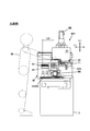
- FIG. 8 schematically illustrates the appearance of the lathe 901.
- FIG. 9 schematically illustrates the movement of the main tool post 40 of the lathe 901 viewed from the Z1 axis direction.
- FIG. 10 schematically illustrates the front of the lathe 901.
- FIG. 11 schematically illustrates work such as setup on the lathe 901.
- a lathe 901 includes a front spindle stock 10, a guide bush 15, a rear spindle stock 20, a main tool post 40, a support base 30, a back tool post 50, and various drive units U1 to U3 on the base 2. .
- the front spindle head drive unit U1 includes a feed mechanism 10z and a Z1 axis motor M1, and moves the front spindle head 10 provided with the front spindle 11 in both directions in the Z1 axis direction.
- the Z1 axis direction is a horizontal direction along the center line AX1 of the front main shaft 11.
- the main tool post drive unit U2 includes feed mechanisms 40x and 40y, an X1 axis motor M2, and a Y1 axis motor (not shown), and moves the main tool post 40 in both directions of the X1 axis direction and the Y1 axis direction.
- the X1 axis direction is the vertical direction and is orthogonal to the Z1 axis direction.
- the Y1 axis direction is a horizontal direction and is orthogonal to the Z1 axis direction and the X1 axis direction.
- the back spindle head drive unit U3 includes feed mechanisms 20x and 20z, an X2 axis motor (not shown), and a Z2 axis motor M5.
- the back spindle base 20 provided with the back spindle 21 is both in the X2 axis direction and the Z2 axis direction. Move in the direction.
- the Z2 axis direction is a horizontal direction along the center line AX2 of the back main shaft 21, and is a horizontal direction along the Z1 axis direction.
- the X2 axis direction is a horizontal direction along the Y1 axis direction and is orthogonal to the Z2 axis direction.
- the support base 30 holds the main tool rest 40 so that the main tool rest 40 can be transferred in the X1 and Y1 axial directions at the side portion 31 facing the back main shaft 21.
- a plurality of first tools are arranged in the Y1 axis direction on the lower surface of the main body 41 of the main tool post 40.
- a plurality of second tools for back surface processing are arranged in the X2 axis direction on the surface (facing surface 51) facing the back main shaft 21 in the back tool rest 50.
- FIG. 9 shows a state ST91 in which the main tool post 40 is disposed at the moving end opposite to the back tool post 50 (right side in FIG. 9) in the Y1 axis direction.
- the lower part of FIG. 9 shows a state ST92 in which the main tool post 40 is arranged at the moving end on the back tool post 50 side (left side in FIG. 9) in the Y1 axis direction.
- the first tool T1 held by the main body 41 of the main tool post 40 is arranged in a horizontal direction orthogonal to the Z1 axis direction because the main tool post 40 moves in the horizontal Y1 axis direction.
- the second tool T2 held on the back tool rest 50 is arranged in a horizontal direction orthogonal to the Z2 axis direction in order to process the workpiece gripped by the back main shaft 21 moving in the horizontal X2 axis direction. For this reason, when the main tool post 40 moves toward the back tool post 50 when viewed from the Z1 axis direction, the first tool T1 and the second tool T2 overlap. Therefore, as shown in FIG. 10, the first tool T1 held on the main tool rest 40 is behind the back tool rest 50, that is, between the side 31 of the support base 30 and the back tool rest 50. A gap CL9 that allows passage is formed.
- the main tool post 40 processes the workpiece, so that chips scattered from the workpiece easily accumulate in the gap CL9.
- the chips accumulated in the gap CL9 are difficult to collect as they are.
- the machining point of the main tool post 40 and the machining point of the back tool post 50 are separated from each other by the gap CL9, and the stroke of the back spindle stock 20 is increased accordingly.
- the second tool T2 is arranged horizontally from the center line AX1 of the front main shaft 11 toward the operator Wr during work such as setup, so that the guide bush 15 at the back is accordingly provided. It is difficult to access etc.
- the second axis direction (X2 axis direction) orthogonal to the center line AX1 of the first main shaft 11 is relative to the first axis direction (Y1 axis direction). And diagonal.
- the 2nd tool post 50 holding the 2nd tool T2 can be made into the position which does not overlap with a plurality of 1st tools T1.
- the second tool T2 and the second tool T2 in the second tool post 50 holding the second tool T2 in the center line direction (Z1 axis direction) of the first main spindle 11 and A portion (range R1) on the extension line of the second tool T2 can be set to a position where it overlaps with the plurality of first tools T1. That is, since the second tool post 50 approaches the side part 31 of the support base 30 that supports the first tool post 40, it becomes difficult for chips to enter between the side part 31 of the support base 30 and the second tool post 50. . Therefore, this aspect 1 can provide the lathe which makes it easy to collect the chips around the second tool post.
- the stroke of the second head stock can be shortened, and the structure constituting the periphery of the second head stock can be reduced, and the cost can be reduced. Can be lowered.
- the guide bush and the like in the back are easily accessible, and workability is good.
- the horizontal distance from the position of the second tool to the center line of the first spindle is the horizontal distance in the comparative example (FIG. 11). Therefore, workability such as setup can be improved in this respect as well.
- the first spindle stock may be fixed so as not to move, or may be movable in the direction of the center line of the first spindle.
- the workpiece protruding from the first main shaft may be supported by the guide bush or may be processed without support of the guide bush.
- Holding the tool by the tool post includes holding the tool unit having the tool by the tool post.
- the first tool post may hold a tool different from the first tool arranged in the first axial direction.
- the support base may support the guide bush or may support the first main shaft.
- the second headstock driving unit may move the second headstock in the center line direction of the second main spindle in addition to the second axis direction.
- the fact that the second axial direction is oblique with respect to the first axial direction means that the second axial direction is not a direction along the first axial direction and the second axial direction is perpendicular to the first axial direction. Means no.
- the second tool post holding the second tool does not overlap with the plurality of first tools in the third axis direction.
- the second tool does not overlap with the plurality of first tools in the third axis direction, and the second tool It means that the second tool post excluding the tool does not overlap with the plurality of first tools in the third axial direction.
- the second tool post holding the second tool overlaps with the plurality of first tools in the direction of the center line of the first spindle with the second tool and the portion on the extension line of the second tool.
- the second tool is overlapped with a plurality of first tools in the direction of the center line of the first spindle.
- (Case 2) In the second tool post excluding the second tool, a portion on the extension line of the second tool in the center line direction of the first spindle overlaps with the plurality of first tools in the center line direction of the first spindle. There is.
- the first tool rest 40 is a third position that does not overlap the second tool rest 50 holding the second tool T2 in the first axial direction (Y1 axial direction).
- the tool T3 may be held.
- the second tool rest 50 holding the second tool T2 is in a position where it can overlap with the third tool T3 in the third axial direction (X1 axial direction). Also good.
- This aspect can improve the freedom of processing while suppressing the increase in size of the machine.
- the lathe 1 may further include a guide bush 15 that is supported through a work W ⁇ b> 1 protruding from the first main shaft 11.
- the first tool post driving unit U2 may move the first tool post 40 in the third axial direction (X1 axial direction) in addition to the first axial direction (Y1 axial direction). This aspect can improve the degree of freedom of processing.
- reference numeral 10 is used for the front spindle as an example of the first spindle
- reference numeral 11 is used for the front spindle as an example of the first spindle
- the back is used for an example of the second spindle.
- Reference numeral 20 is used for the headstock
- reference numeral 21 is used for the back spindle as an example of the second spindle
- reference numeral 40 is used for the main tool post as an example of the first tool post
- a back tool as an example of the second tool post.
- the reference numeral 50 is used, the main tool post driving unit as an example of the first tool post driving unit is used with the reference symbol U2, and the rear main shaft driving unit as an example of the second main spindle drive unit is used with the reference symbol U3. To do.
- FIG. 1 schematically illustrates the configuration of a spindle movement type NC (numerical control) lathe 1 as an example of a lathe.
- FIG. 2 schematically illustrates the appearance of the lathe 1.
- FIG. 3 schematically illustrates the movement of the main tool post 40.
- FIG. 4 schematically illustrates a main part of the lathe 1.
- FIG. 5 is a front view schematically illustrating the lathe 1. Note that the drawings referred to in this specification are merely examples for explaining the present technology, and do not limit the present technology. Moreover, the description of the positional relationship of each part is only an example.
- change the left / right direction to the up / down direction or the front / rear direction change the up / down direction to the left / right direction or the front / rear direction, change the front / rear direction to the left / right direction or the up / down direction, or change the rotation direction to the reverse direction. It is also included in the present technology. Further, the same direction, position, etc. are not limited to exact matching, but include deviation from exact matching due to an error.
- a lathe 1 shown in FIG. 1 and the like has a front spindle stock 10, a guide bush 15, a rear spindle stock 20, a main tool post 40, a support tool 30, a back tool post 50, various driving units U1 to U3 on a base 2.
- An NC device 70 is provided.
- the main parts of the various platforms 2, 10, 20, 30, 40, 50, the guide bush 15, and the tools T1 to T4 can be made of, for example, metal.
- the NC device 70 controls the operations of the front spindle stock 10, the rear spindle stock 20, the main tool post 40, the drive units U1 to U3, and the like.
- a lathe 1 shown in FIG. 2 and the like has X1, Y1, Z1, X2, and Z2 axes as control axes.
- the X1, Y1, Z1, X2, and Z2 axis directions mean directions along the X1, Y1, Z1, X2, and Z2 axes.
- the workpiece W0 shown in FIG. 1 is a generic term for the workpiece W1 that is the target of the front surface processing and the workpiece W2 that is the target of the back surface processing.
- the front head stock 10 provided with the front main shaft 11 is movable with respect to the base 2 in the Z1 axis direction along the center line AX1 of the front main shaft 11.
- the Z1 axis direction shown in FIG. 2 etc. is a horizontal direction.
- the NC device 70 controls the position of the front headstock 10 in the Z1 axis direction via the front headstock drive unit U1.
- the front spindle 11 grips a columnar (rod-like) workpiece W1 inserted in the Z1 axis direction in a collet (not shown) so as to be releasable, and the workpiece W1 is centered on a spindle centerline AX1 along the longitudinal direction of the workpiece W1. Rotate.
- the guide bush 15 is attached to a support base 30 in front of the front main shaft 11.
- the guide bush 15 disposed in front of the front main shaft 11 supports a longitudinal workpiece W1 penetrating the front main shaft 11 so as to be slidable in the Z1 axis direction, and is centered on the main shaft center line AX1 in synchronization with the front main shaft 11.
- the guide bush 15 is supported through the workpiece W1 protruding from the front main shaft 11. Due to the presence of the guide bush 15, the bending of the elongated workpiece W1 is suppressed and high-precision machining is performed.
- the back spindle stock 20 provided with the back spindle 21 is in the Z2 axis direction along the center line AX2 of the back spindle 21 and the X2 axis direction (second axis direction) orthogonal to the spindle center line AX2 with respect to the base 2.
- the Z2 axis direction is a direction along the Z1 axis direction.
- the Z2 axis direction shown in FIG. 2 etc. is the horizontal direction.
- the X2 axis direction is not along any of the X1 and Y1 axis directions that are the moving directions of the main tool post 40, but is oblique to the horizontal Y1 axis direction (example of the first axis direction) and is vertical.
- the angle ⁇ (see FIG. 4) formed by the horizontal Y1 axis direction and the oblique X2 axis direction is not particularly limited, and can be, for example, about 10 to 80 °.
- the angle may be about 20 to 70 °, or it may be about 40 ° or less with emphasis on suppressing the height of the machine.
- the rear main shaft 21 is movable in the X2 axis direction through a position facing the front main shaft 11 via the guide bush 15. Referring to FIGS. 2 and 4, the back main shaft 21 moves in both directions in the X2 axis direction from the center line AX1 of the front main shaft 11 toward the front side (left side in FIG. 4). To do.
- the NC device 70 controls the position of the back spindle stock 20 in the X2 and Z2 axis directions via the back spindle drive unit U3.
- the back main shaft 21 receives the work W0 from the front main shaft 11 at a position facing the front main shaft 11 via the guide bush 15, and releasably grips the work W2 inserted in the Z2 axis direction with a collet (not shown).
- the back spindle 21 is centered on the spindle centerline AX2 along the longitudinal direction of the workpiece W2. As a result, the workpiece W2 is rotated.
- the main tool post 40 is supported by the support stand 30 so as to be movable in the X1 and Y1 axis directions perpendicular to the center line AX1 of the front main shaft 11 with respect to the side portion 31 facing the back main shaft 21.
- the X1 axis direction (example of the third axis direction) is a vertical direction and is orthogonal to the Z1 axis direction.
- the Y1 axis direction (example of the first axis direction) is a horizontal direction and is orthogonal to the Z1 axis direction and the X1 axis direction.
- the NC device 70 controls the position of the main tool post 40 in the X1 and Y1 axial directions via the main tool post driving unit U2.
- the main tool post 40 includes a body portion 41 that holds a plurality of first tools T1, an extension portion 42 that holds a plurality of third tools T3, and a plurality of fourth tools T4.
- This is a comb-type tool rest having branch portions 43 to be held.
- the main body 41 has a surface (facing surface 41a) that faces down and can face the back tool post 50 in the X1 axis direction, and holds a plurality of first tools T1 arranged in the Y1 axis direction on the facing surface 41a.
- FIG. 4 shows six cutting tools and three drills as the first tool T1, but the type and number of the first tool T1 are not limited to the example shown in FIG.
- the extension portion 42 extends downward from the portion (right side in FIG. 4) opposite to the back tool rest 50 with respect to the center line AX1 of the front main shaft 11 in the Y1 axis direction on the opposing surface 41a. ing.
- the extension portion 42 has a surface (facing surface 42a) that can face the back tool post 50 in the Y1 axis direction, and holds a plurality of third tools T3 arranged in the X1 axis direction on the facing surface 42a. Although three drills are shown as the third tool in FIG. 4, the type and number of the third tool T3 are not limited to the example shown in FIG. As shown in the lower part of FIG.
- the plurality of third tools T3 includes a back tool rest 50 holding a plurality of second tools T2 for back machining and a Y1 axis even when the main tool rest 40 moves in the Y1 axis direction. It is in a position that does not overlap in the direction.
- the branch portion 43 extends from the facing surface 41 a to the back main shaft 21 side and extends downward in the X1 axis direction between the arrangement of the first tools T1 and the extension portion 42.
- the branch portion 43 has a surface facing the side portion 31 of the support base 30 in the Z1 axis direction, and holds a plurality of fourth tools T4 arranged in the X1 axis direction on the facing surface.
- the plurality of fourth tools T4 are in positions that do not overlap in the Y1 axis direction with the back tool rest 50 holding the plurality of second tools T2 even if the main tool rest 40 moves in the Y1 axis direction.
- the branch portion 43 also has a surface that can face the back main shaft 21 in the Z1 axis direction, and can hold a plurality of tools arranged in the X1 axis direction on this facing surface.
- the main tool post 40 holds a plurality of tools T1, T3, and T4 that process the workpiece W1 that protrudes from the front spindle 11 and penetrates the guide bush 15.
- the support base 30 is fixed so as not to move with respect to the base 2 between the front main spindle 10 and the rear main spindle 20, and extends from the base 2 to the upper side in the X1 axis direction.
- the support base 30 holds a guide bush 15 that allows the workpiece W1 protruding from the front main shaft 11 to pass therethrough.
- the side 31 facing the back main shaft 21 in the support base 30 supports the main tool rest 40 so that it can be transferred in the X1 and Y1 axis directions, and fixes the attached back tool rest 50 so as not to move. Note that the side portion 31 of the support base 30 is located closer to the front main shaft 11 than the tip W1a of the workpiece W1 protruding from the front main shaft 11 and penetrating the guide bush 15.
- the back tool post 50 is fixed so as not to move with respect to the side 31 of the support base 30.
- the back tool post 50 has a surface (facing surface 51) facing the back main shaft 21, and holds a plurality of second tools T2 for back surface processing arranged in the X2 axis direction on the facing surface 51.
- 2 and 4 show four drills as the second tool T2, the type and number of the second tool T2 are not limited to the examples shown in FIGS.
- the back tool post 50 holds the plurality of second tools T2 for processing the workpiece W2 held by the back spindle 21.
- a tool unit having a tool may be detachably attached to the main tool post 40 and the back tool post 50. Also in this case, the tool rests 40 and 50 hold the tool. Further, a tool rest other than the tool rests 40 and 50 may be installed on the lathe 1.
- the back tool post 50 holding the plurality of second tools T2 is in a position that does not overlap the plurality of first tools T1 in the X1 axis direction.
- the upper limit (boundary B2) of the back tool rest 50 holding the plurality of second tools T2 is lower than the lower limit (boundary B1) of the movement range of the plurality of first tools T1 in the X1 axis direction. It is in. For this reason, the back tool post 50 holding the plurality of second tools T2 is in a position that does not overlap with the plurality of first tools T1.
- This state is shown as a state ST1 in the upper part of FIG.
- 3 shows a state ST1 in which the main tool post 40 is arranged at the moving end opposite to the back tool post 50 (the right side in FIG. 3) in the Y1-axis direction.
- 3 shows a state ST2 in which the main tool post 40 is disposed at the moving end on the back tool post 50 side (left side in FIG. 3) in the Y1 axis direction.
- the first tool T1 held by the main body 41 of the main tool post 40 is arranged in a horizontal direction orthogonal to the Z1 axis direction because the main tool post 40 moves in the horizontal Y1 axis direction.
- the second tool T2 held on the back tool rest 50 processes a workpiece gripped by the back main spindle 21 moving in the X2 axis direction at a portion descending toward the front side, and therefore a plurality of first tools T2 in the X1 axis direction are processed. They are arranged in the X2 axis direction below the tool T1. For this reason, when viewed from the Z1 axis direction, the first tool T1 and the second tool T2 do not overlap even if the main tool post 40 moves to the back tool post 50 side.
- the back of the back tool post 50 is placed behind the back tool post 50, that is, so that no gap is formed between the side 31 of the support stand 30 and the back tool post 50. It can be attached to the side part 31.
- the back tool post 50 holding the plurality of second tools T2 includes a plurality of second tools T2 in the Z1 axis direction and a portion (range R1) on an extension line of the plurality of second tools T2 having a plurality of second tools T2. There is an overlap with one tool T1.
- the range R1 means a range from the back surface of the back tool rest 50 to the tip of the second tool T2 in the Z1 axis direction. Since the first tool T1 is in the range R1 shown in FIG.
- the back tool post 50 holding the plurality of second tools T2 is on the extended lines of the plurality of second tools T2 and the plurality of second tools T2.
- the portion (range R1) is at a position where there is an overlap with the plurality of first tools T1 in the Z1 axis direction.
- the plurality of third tools T3 held by the extension 42 of the main tool post 40 has a plurality of second tools even if the main tool post 40 moves in the Y1 axis direction.
- the back tool post 50 holding the tool T2 is in a position that does not overlap in the Y1 axis direction.
- the back tool post in which the boundary B4 on the third tool T3 side of the back tool rest 50 holding the plurality of second tools T2 in the Y1 axis direction is within the movement range of the plurality of third tools T3. It is on the back tool post 50 side from the boundary B3 on the 50 side. For this reason, the plurality of third tools T3 are in positions that do not overlap with the back tool post 50 holding the plurality of second tools T2.
- the back tool post 50 holding the second tool T2 can be arranged to overlap with a plurality of third tools T3 moving in the X1 axis direction.
- the back tool post 50 holding the second tool T2 is in a position where it can overlap with the plurality of third tools T3.
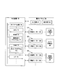
- FIG. 6 schematically illustrates the configuration of the electric circuit of the NC lathe 1.
- the NC device 70 includes an operation panel 80, a Z1-axis motor M1, an X1-axis motor M2, a Y1-axis motor M3, an X2-axis motor M4, a Z2-axis motor M5, and a rotary motor for the front spindle 11.
- a rotary motor (not shown) for the back main shaft 21, a rotary motor (not shown) for a rotary drill, and the like are connected.
- the NC device 70 includes a CPU (Central Processing Unit) 71, a ROM (Read Only Memory) 72 as a semiconductor memory, a RAM (Random Access Memory) 73 as a semiconductor memory, a timer circuit 74, an I / F (interface) 75, and the like. have.
- I / Fs of the operation panel 80 and the servo motors M1 to M5 are collectively indicated as I / F75.
- the ROM 72 an interpretation execution program P1 for interpreting and executing the machining program P2 is written.
- the RAM 73 stores a machining program P2 created by the user.
- the machining program is also called an NC program.
- the CPU 71 causes the computer to function as the NC device 70 by using the RAM 73 as a work area and executing the interpretation execution program P1 recorded in the ROM 72.
- the interpretation execution program P1 may be realized by other means such as ASIC (Application Specific Integrated Circuit).
- the operation panel 80 includes an input unit 81 and a display unit 82, and functions as a user interface of the NC device 70.
- the input unit 81 includes, for example, a button or a touch panel for receiving an operation input from an operator.
- the display unit 82 includes, for example, a display that displays various settings regarding the operation input received from the operator and various information related to the NC lathe 1.
- the operator can store the machining program P2 in the RAM 73 using the operation panel 80 or an external computer.
- the front headstock drive unit U1 includes a feed mechanism 10z and a Z1-axis motor M1, and moves the front headstock 10 provided with the front main shaft 11 in both directions in the Z1 axis direction.
- the feed mechanism 10z includes, for example, a pair of rails and ball screws installed on the base 2, and a pair of guide members and nuts fixed to the bottom surface of the front spindle stock 10.
- a guide member is slidably fitted to each rail, and a nut is screwed to the ball screw.
- the feeding mechanism 10z may use a slidable fitting structure between the dovetail groove and the ant.
- the main tool post drive unit U2 includes feed mechanisms 40x and 40y, an X1-axis motor M2, and a Y1-axis motor M3, and moves the main tool post 40 in both directions of the X1 axis direction and the Y1 axis direction.
- the feed mechanism 40x is constituted by, for example, a dovetail groove and a ball screw arranged on the slide base 35 that slides in the Y1-axis direction, and a dovetail and a nut arranged on the back surface (the front headstock 10 side) of the main tool post 40. Is done.
- an ant is slidably fitted into the dovetail groove and a nut is screwed into the ball screw.
- the feed mechanism 40y includes, for example, dovetail grooves and ball screws arranged at the top of the side portion 31 of the support base 30, and dovetails and nuts arranged on the back surface of the slide base 35 (on the front headstock 10 side). The Here, it is assumed that an ant is slidably fitted into the dovetail groove and a nut is screwed into the ball screw.
- the feed mechanisms 40x and 40y may have a slidable fitting structure between the rail and the guide member in addition to the slidable fitting structure between the dovetail groove and the ant.
- the feed mechanism 40x can be configured by a pair of rails and a ball screw installed on the slide base 35, and a guide member and a nut fixed to the back surface of the main tool post 40.
- the feed mechanism 40 y can be configured by a pair of rails and ball screws installed on the upper portion of the side portion 31 of the support base 30, and a guide member and a nut fixed to the back surface of the slide base 35.
- the back spindle head drive unit U3 has feed mechanisms 20x, 20z, an X2 axis motor M4, and a Z2 axis motor M5, and moves the back spindle head 20 provided with the back spindle 21 in both directions of the X2 axis direction and the Z2 axis direction.
- the feed mechanism 20x includes, for example, a pair of rails and ball screws installed on the base 2, and a pair of guide members and nuts fixed to the bottom surface of the slide base 5 that slides in the X2 axial direction.
- a guide member is slidably fitted to each rail, and a nut is screwed to the ball screw.
- the feed mechanism 20z includes, for example, a pair of rails and ball screws installed on the slide base 5, and a pair of guide members and nuts fixed to the bottom surface of the back spindle stock 20.
- a guide member is slidably fitted to each rail, and a nut is screwed to the ball screw.
- the back spindle stock 20 moves in the Z2 axis direction with respect to the base 2 via the slide base 5.
- a slidable fitting structure between the dovetail groove and the ant may be used.
- the feed mechanism 20 x can be configured by a dovetail groove and a ball screw arranged on the base 2, and an ant and nut arranged on the bottom surface of the slide base 5.
- the feed mechanism 20 z can be configured by a dovetail groove and a ball screw arranged on the slide base 5 and an dovetail and a nut arranged on the bottom surface of the back spindle stock 20.
- the workpiece machining control is performed, for example, as follows. First, the NC device 70 moves forward while gripping the workpiece W1 on the front spindle 11, projects the tip W1a from the guide bush 15 by a predetermined amount, and appropriately rotates the workpiece W1 to drive the main tool post 40 to perform front machining. Process. After the predetermined front surface machining, the NC device 70 places the back main shaft 21 at a position where the center lines AX1 and AX2 meet each other, advances the front main shaft 11 while gripping the work W1, and moves the back main shaft 21 to the back main shaft 21 after the front processing. To hold.
- the NC device 70 drives the main tool post 40 and separates the workpieces W1 and W2 with a parting tool, and then appropriately drives the workpiece W2 to drive the rear spindle stock 20 and the main tool post 40 as necessary. To perform backside processing. At this time, the back surface processing by the second tool T2 held on the back tool rest 50 is performed. After the predetermined back surface processing, the NC device 70 drives the back headstock 20 to a predetermined product discharge position to discharge the workpiece W2, that is, the product after the back surface processing.
- the X2 axis direction orthogonal to the center line AX1 of the first main shaft 11 is oblique to the horizontal Y1 axis direction. Therefore, as in the state ST2 in FIG. 3, the back tool rest 50 holding the plurality of second tools T2 in the vertical X1 axis direction can be positioned so as not to overlap the plurality of first tools T1. Due to this positional relationship, as shown in FIG. 5, in the Z1 axis direction, the plurality of second tools T2 of the back tool post 50 holding the plurality of second tools T2 and the extended lines of the plurality of second tools T2 The part (range R1) in the position can overlap with the plurality of first tools T1.
- this example can shorten the stroke of the back headstock 20 in the Z2 axis direction, can reduce the structure constituting the periphery of the back headstock 20, and can reduce the size of the machine itself. Can reduce costs.
- the guide bush at the back is at the time of work such as setup.
- the second tool T2 may become an obstacle to access to etc.
- the second tool T2 is arranged at a position lower than the center line AX1 of the front main shaft 11 as in this specific example shown in FIG. 7, the operator Wr is in the back when performing work such as setup. It is easy to access the guide bush 15 and the like, and the workability is good.
- the horizontal distance L1 from the position of the second tool T2 on the back tool post 50 to the center line AX1 of the front spindle 11 is shorter than the horizontal distance L9 in the comparative example shown in FIG. Improved workability.
- a lathe to which the present technology can be applied may be a lathe that does not have a guide bush and processes a workpiece held by a main shaft.
- the back tool post 50 may be movable in a control axis direction that is orthogonal to the center line AX2 of the back main shaft 21 and that is different from the X2 axis direction.
- two or more rows of the second tools T2 can be arranged on the back tool post 50.
- the number of the second tool T2 held on the back tool rest 50 in the X2 axis direction may be one.
- the workpiece is moved in the Z1 axis direction. Can be processed. Even if the rear headstock does not move in the Z2 axis direction, for example, by gripping the workpiece with the front spindle that matches the spindle centerline and moving the front headstock in the Z1 axis direction, the workpiece is moved in the Z2 axis direction. It can be moved and processed. Even when the main tool post does not move in the X1 axis direction, for example, the workpiece can be machined by moving the front spindle table in the X1 axis direction. Either case is included in the present technology.
- the mounting location of the back tool post is not limited to the side of the support base, but may be the top surface of the base.
- chips do not accumulate behind the back tool post, and chip recovery performance is improved.
- this mode 1 has the effect of making it easier to collect chips around the back tool post.
- the main tool post does not have at least one of the third tool T3 and the fourth tool T4, the basic effect of facilitating the collection of chips around the back tool post can be obtained.
Landscapes
- Engineering & Computer Science (AREA)
- Mechanical Engineering (AREA)
- Turning (AREA)
Abstract
L'invention concerne un tour dans lequel des copeaux autour d'un porte-outil sont facilement récupérés. Un tour (1) comprend des poupées (10, 20), des porte-outils (40, 50), une base de support (30) et des unités d'entraînement (U2, U3). La base de support (30) soutient le premier porte-outil (40) sur un côté (31) de façon à être transportable. La première unité d'entraînement de porte-outil U2 déplace le premier porte-outil (40) dans une première direction axiale (direction de l'axe Y1) qui est orthogonale à la ligne centrale AX1 d'une première broche (11). La seconde unité d'entraînement de poupée fixe U3 déplace la seconde poupée fixe (20) dans une seconde direction axiale (direction de l'axe X2) qui est orthogonale à la ligne centrale AX1 de la première broche (11) et inclinée par rapport à la première direction axiale (direction de l'axe Y1). Le second porte-outil (50) retenant un second outil T2 est dans une position qui ne chevauche pas une pluralité de premiers outils T1 dans une troisième direction axiale (direction de l'axe X1) et est dans une position dans laquelle le second outil T2 et une partie (plage R1) sur une ligne étendue du second outil T2 chevauchent la pluralité de premiers outils T1 dans la direction de la ligne centrale (direction de l'axe Z1) de la première broche (11).
Priority Applications (3)
| Application Number | Priority Date | Filing Date | Title |
|---|---|---|---|
| CN201880085119.XA CN111556799A (zh) | 2018-02-26 | 2018-12-21 | 车床 |
| EP18907279.6A EP3733330B1 (fr) | 2018-02-26 | 2018-12-21 | Tour |
| US16/940,725 US20200368821A1 (en) | 2018-02-26 | 2020-07-28 | Lathe |
Applications Claiming Priority (2)
| Application Number | Priority Date | Filing Date | Title |
|---|---|---|---|
| JP2018-031965 | 2018-02-26 | ||
| JP2018031965A JP6880437B2 (ja) | 2018-02-26 | 2018-02-26 | 旋盤 |
Related Child Applications (1)
| Application Number | Title | Priority Date | Filing Date |
|---|---|---|---|
| US16/940,725 Continuation US20200368821A1 (en) | 2018-02-26 | 2020-07-28 | Lathe |
Publications (1)
| Publication Number | Publication Date |
|---|---|
| WO2019163280A1 true WO2019163280A1 (fr) | 2019-08-29 |
Family
ID=67687598
Family Applications (1)
| Application Number | Title | Priority Date | Filing Date |
|---|---|---|---|
| PCT/JP2018/047194 Ceased WO2019163280A1 (fr) | 2018-02-26 | 2018-12-21 | Tour |
Country Status (6)
| Country | Link |
|---|---|
| US (1) | US20200368821A1 (fr) |
| EP (1) | EP3733330B1 (fr) |
| JP (1) | JP6880437B2 (fr) |
| CN (1) | CN111556799A (fr) |
| TW (1) | TWI763940B (fr) |
| WO (1) | WO2019163280A1 (fr) |
Families Citing this family (2)
| Publication number | Priority date | Publication date | Assignee | Title |
|---|---|---|---|---|
| JP7655816B2 (ja) * | 2021-08-19 | 2025-04-02 | 株式会社ツガミ | 工作機械 |
| DE112021008382T5 (de) * | 2021-10-22 | 2024-08-01 | Fuji Corporation | Drehmaschine mit zwei nach vorne gewandten Spindeln |
Citations (4)
| Publication number | Priority date | Publication date | Assignee | Title |
|---|---|---|---|---|
| JPH055305U (ja) * | 1991-04-08 | 1993-01-26 | セイコー精機株式会社 | 主軸移動形自動旋盤 |
| JPH0557504A (ja) * | 1991-09-03 | 1993-03-09 | Amada Co Ltd | 棒材加工装置 |
| JPH08118203A (ja) * | 1994-10-25 | 1996-05-14 | Citizen Watch Co Ltd | Nc旋盤の制御方法及び制御装置 |
| WO2002024386A1 (fr) | 2000-09-22 | 2002-03-28 | Citizen Watch Co., Ltd. | Tour automatique |
Family Cites Families (7)
| Publication number | Priority date | Publication date | Assignee | Title |
|---|---|---|---|---|
| DE20021264U1 (de) * | 2000-12-15 | 2001-04-05 | Wilhelm Fette Gmbh, 21493 Schwarzenbek | Schaftfräser für die Bearbeitung von Werkstücken aus Nichteisenmetall oder Kunststoff |
| JP4090888B2 (ja) * | 2001-05-15 | 2008-05-28 | シチズンホールディングス株式会社 | 数値制御旋盤及びこの数値制御旋盤によるワークの加工方法 |
| DE10130760A1 (de) * | 2001-06-22 | 2003-01-09 | Traub Drehmaschinen Gmbh | Drehmaschine |
| DE10131733A1 (de) * | 2001-06-22 | 2003-01-09 | Traub Drehmaschinen Gmbh | Drehmaschine |
| JP2005111631A (ja) * | 2003-10-09 | 2005-04-28 | Star Micronics Co Ltd | Nc自動旋盤 |
| EP1632309B1 (fr) * | 2004-09-06 | 2007-06-20 | Tornos SA | Dispositif d'usinage en contre-opération dans un tour multibroches |
| CN105817654B (zh) * | 2016-05-31 | 2018-08-28 | 程泰机械(吴江)有限公司 | 一种硬轨数控车床 |
-
2018
- 2018-02-26 JP JP2018031965A patent/JP6880437B2/ja active Active
- 2018-10-18 TW TW107136732A patent/TWI763940B/zh active
- 2018-12-21 EP EP18907279.6A patent/EP3733330B1/fr active Active
- 2018-12-21 CN CN201880085119.XA patent/CN111556799A/zh active Pending
- 2018-12-21 WO PCT/JP2018/047194 patent/WO2019163280A1/fr not_active Ceased
-
2020
- 2020-07-28 US US16/940,725 patent/US20200368821A1/en not_active Abandoned
Patent Citations (4)
| Publication number | Priority date | Publication date | Assignee | Title |
|---|---|---|---|---|
| JPH055305U (ja) * | 1991-04-08 | 1993-01-26 | セイコー精機株式会社 | 主軸移動形自動旋盤 |
| JPH0557504A (ja) * | 1991-09-03 | 1993-03-09 | Amada Co Ltd | 棒材加工装置 |
| JPH08118203A (ja) * | 1994-10-25 | 1996-05-14 | Citizen Watch Co Ltd | Nc旋盤の制御方法及び制御装置 |
| WO2002024386A1 (fr) | 2000-09-22 | 2002-03-28 | Citizen Watch Co., Ltd. | Tour automatique |
Non-Patent Citations (1)
| Title |
|---|
| See also references of EP3733330A4 |
Also Published As
| Publication number | Publication date |
|---|---|
| JP2019147202A (ja) | 2019-09-05 |
| US20200368821A1 (en) | 2020-11-26 |
| TW201936298A (zh) | 2019-09-16 |
| EP3733330A1 (fr) | 2020-11-04 |
| EP3733330B1 (fr) | 2024-09-04 |
| EP3733330A4 (fr) | 2021-09-22 |
| JP6880437B2 (ja) | 2021-06-02 |
| TWI763940B (zh) | 2022-05-11 |
| CN111556799A (zh) | 2020-08-18 |
Similar Documents
| Publication | Publication Date | Title |
|---|---|---|
| JP4997240B2 (ja) | 複数の刃物台を備える自動旋盤 | |
| JPS60207746A (ja) | 多面加工機械 | |
| JP4681191B2 (ja) | 2主軸対向旋盤 | |
| TWI763939B (zh) | 車床 | |
| WO2019082508A1 (fr) | Tour sur lequel est montée une unité d'outil | |
| JP6880437B2 (ja) | 旋盤 | |
| JP4270421B2 (ja) | 複合加工機械及び複合加工方法 | |
| JP2828232B2 (ja) | 対向主軸旋盤 | |
| JPH03208501A (ja) | 数値制御複合旋盤 | |
| US10695842B2 (en) | Horizontal lathe machine with a mid-spindle and two tooling turrets | |
| JP4498631B2 (ja) | 主軸移動型自動旋盤 | |
| JP3947799B2 (ja) | ターニングセンタ | |
| JP2003062701A (ja) | 対向主軸cnc旋盤 | |
| JP2835745B2 (ja) | 2主軸対向旋盤 | |
| KR20130077293A (ko) | 다중 주축 및 다중 테이블을 구비한 공작기계 | |
| JPH10328901A (ja) | 対向主軸旋盤 | |
| JP2005153084A (ja) | 2主軸対向旋盤 | |
| CN117600853A (zh) | 一种卧式加工中心 | |
| JPH0661642B2 (ja) | 数値制御自動旋盤 | |
| JPH06114601A (ja) | 数値制御旋盤 | |
| JP2006123046A (ja) | 旋盤 | |
| JP2001198703A (ja) | 複合移動軸を備えた数値制御工作機械及びこの数値制御工作機械による加工方法 | |
| JPH04118902U (ja) | 旋 盤 | |
| HK1141487A (en) | A multiple-spindle turning machine having workpiece supporting spindles movable in the direction of the longitudinal axis of the machine | |
| JPS63306802A (ja) | 工作機械 |
Legal Events
| Date | Code | Title | Description |
|---|---|---|---|
| 121 | Ep: the epo has been informed by wipo that ep was designated in this application |
Ref document number: 18907279 Country of ref document: EP Kind code of ref document: A1 |
|
| ENP | Entry into the national phase |
Ref document number: 2018907279 Country of ref document: EP Effective date: 20200729 |
|
| NENP | Non-entry into the national phase |
Ref country code: DE |