WO2019163380A1 - Système de production de vêtement, procédé de commande associé, procédé de connexion d'unité et vêtement - Google Patents
Système de production de vêtement, procédé de commande associé, procédé de connexion d'unité et vêtement Download PDFInfo
- Publication number
- WO2019163380A1 WO2019163380A1 PCT/JP2019/002089 JP2019002089W WO2019163380A1 WO 2019163380 A1 WO2019163380 A1 WO 2019163380A1 JP 2019002089 W JP2019002089 W JP 2019002089W WO 2019163380 A1 WO2019163380 A1 WO 2019163380A1
- Authority
- WO
- WIPO (PCT)
- Prior art keywords
- unit
- units
- base
- connection
- hole
- Prior art date
- Legal status (The legal status is an assumption and is not a legal conclusion. Google has not performed a legal analysis and makes no representation as to the accuracy of the status listed.)
- Ceased
Links
Images









Classifications
-
- G—PHYSICS
- G06—COMPUTING OR CALCULATING; COUNTING
- G06F—ELECTRIC DIGITAL DATA PROCESSING
- G06F30/00—Computer-aided design [CAD]
- G06F30/10—Geometric CAD
- G06F30/12—Geometric CAD characterised by design entry means specially adapted for CAD, e.g. graphical user interfaces [GUI] specially adapted for CAD
-
- A—HUMAN NECESSITIES
- A41—WEARING APPAREL
- A41D—OUTERWEAR; PROTECTIVE GARMENTS; ACCESSORIES
- A41D1/00—Garments
-
- A—HUMAN NECESSITIES
- A41—WEARING APPAREL
- A41H—APPLIANCES OR METHODS FOR MAKING CLOTHES, e.g. FOR DRESS-MAKING OR FOR TAILORING, NOT OTHERWISE PROVIDED FOR
- A41H43/00—Other methods, machines or appliances
-
- A—HUMAN NECESSITIES
- A44—HABERDASHERY; JEWELLERY
- A44B—BUTTONS, PINS, BUCKLES, SLIDE FASTENERS, OR THE LIKE
- A44B99/00—Subject matter not provided for in other groups of this subclass
-
- G—PHYSICS
- G06—COMPUTING OR CALCULATING; COUNTING
- G06F—ELECTRIC DIGITAL DATA PROCESSING
- G06F30/00—Computer-aided design [CAD]
-
- G—PHYSICS
- G06—COMPUTING OR CALCULATING; COUNTING
- G06F—ELECTRIC DIGITAL DATA PROCESSING
- G06F2111/00—Details relating to CAD techniques
- G06F2111/16—Customisation or personalisation
-
- G—PHYSICS
- G06—COMPUTING OR CALCULATING; COUNTING
- G06F—ELECTRIC DIGITAL DATA PROCESSING
- G06F2113/00—Details relating to the application field
- G06F2113/12—Cloth
Definitions
- the present invention relates to a garment production system, its control method, and garment.
- Clothes can be broadly classified into ready-made clothes that are mass-produced with a fixed design and tailored clothes that are produced in a single product with a design tailored to the user. Originally, it is preferable that the clothes are only for the user according to the user's fashion sense and values. However, in general, the production of tailored clothes takes time, and it is difficult to efficiently produce clothes with an original design suitable for each user. In view of this, techniques have been proposed in which clothes are divided into a plurality of pieces and managed so that the combination of pieces can be changed (Patent Documents 1 and 2).
- the present invention has been made in view of the above problems, and an object thereof is to provide a garment production system, a control method thereof, and a garment capable of efficiently producing garments according to the user's wishes. It is in.
- a garment production system includes a basic information acquisition unit that acquires basic information including data related to a user and type information that specifies a predetermined garment type, and a predetermined garment based on the basic information.
- a pattern data generation unit that generates pattern data of each unit that constitutes each predetermined area included in the unit, and a unit generation unit that generates each unit based on the pattern data.
- the pattern data generation unit When change request information for requesting a change of a part of a predetermined garment is acquired, the pattern data generation unit generates pattern data corresponding to the change based on the change request information, and the unit generation unit The unit corresponding to the change may be generated based on the pattern data corresponding to the change.
- An assembly unit for assembling a predetermined garment by connecting the units in a predetermined arrangement may be further provided.
- the change request information may be acquired after a predetermined garment assembled by the assembly unit is shipped to a predetermined destination.
- the assembly unit may assemble the predetermined clothes by replacing a part of each unit constituting the predetermined clothes with a unit corresponding to the change.
- Units corresponding to the change may be shipped to a predetermined destination.
- a housing that houses the basic information acquisition unit, the pattern data generation unit, and the unit generation unit may be further provided, and the housing may be configured to be portable.
- the user who acquires the predetermined clothes may be different from the user who acquires the predetermined clothes assembled by the assembly unit in response to the change.
- the garment production system includes a computer and a processing device controlled by the computer, and the computer includes data relating to a user and type information designating a predetermined garment type. Is obtained, and based on the obtained basic information, pattern data of each unit that constitutes each predetermined area included in the predetermined clothing is generated, and the operation of the processing apparatus is controlled based on the pattern data. Each unit is generated, and when change request information requesting a change of a part of a predetermined garment is obtained, pattern data corresponding to the change is generated based on the change request information, and the change is made. A unit corresponding to the change is generated by controlling the operation of the processing apparatus based on the corresponding pattern data.
- a garment includes a plurality of units and a fastener for connecting the plurality of units, and the fastener is connected across the plurality of units on the back side of the plurality of units.
- a first contact portion that contacts the surface of the unit, and a second contact portion that is provided at the other end of the shaft.
- It has a base part which is located on the connection base side with respect to the contact part and the second contact part contacts, and a pair of pressing parts which are provided at positions where the pins are sandwiched on the connection base side with respect to the base part and press the connection base.
- the base may be formed with a pair of slits extending from the opposite side of the position where each pressing portion is provided to each pressing portion toward each pressing portion and communicating with the through hole.
- a semi-cylindrical pressing piece for pressing the connection base may be provided at the tip of each pressing portion.
- a fastener is a fastener for connecting a plurality of units in a garment composed of a plurality of units, and the fastener includes a pin and a fitting member, A pin base, a shaft extending from the pin base, and a fitting portion provided at a tip of the shaft and fitted into the fitting member.
- the fitting member includes a ring-shaped fitting base portion and a fitting base portion.
- a plurality of insertion pieces provided on the inner periphery, and the plurality of insertion pieces form insertion holes into which the insertion portions are inserted by the inner end portions thereof, and the insertion holes are expanded and contracted by elastic deformation. To do.
- the plurality of insertion pieces may protrude inward from the inner periphery of the insertion base.
- the plurality of insertion pieces are constituted by three insertion pieces and are provided at equal intervals along the circumferential direction of the insertion base, and each insertion piece is separated from the inner peripheral surface of the insertion base.
- You may have the center part which is provided and forms a to-be-inserted hole, and the connection part located in the both ends of the center part and connected to the internal peripheral surface.
- a unit connection structure is a unit connection structure in which at least two units are connected by the above-described fastener, and a first connection hole is formed on at least one side of each unit.
- one of the two units connected to each other is formed with a second connection hole positioned inside the first connection hole, and the first communication hole is closer to the pin base than the second connection hole.
- the portion between the first communication hole and the second connection hole of one unit covers the outer periphery of the pin base and at least one side so that the first connection hole and the second connection hole
- the shaft and the insertion portion are penetrated and attached to the pin, and the other unit of the two units is connected to the first connection hole in a state where the first communication hole is located on one unit side with respect to the second connection hole.
- Hole and second series And shaft and fitting portion into the hole is through is mounted on the pin, fitting portion is fitted into the insertion hole of the insert member, the two units, is sandwiched between the pin base and the insert member is connected to each other.
- a garment according to still another aspect of the present invention includes a plurality of units and the fastener for connecting the plurality of units, and is configured by connecting adjacent units by the connecting structure of the units. Yes.
- FIG. 1 is an overall configuration diagram of a garment production system. It is explanatory drawing which shows the structural example of a database. It is explanatory drawing which shows the utilization method of a garment production system. It is explanatory drawing which concerns on 2nd Example and shows the other usage example of a clothing production system. It is explanatory drawing in the case of comprising according to 3rd Example so that a clothing production system can be carried. It is explanatory drawing in the case of incorporating chips, such as a sensor, in a unit or a fastener concerning 4th Example. It is explanatory drawing at the time of enabling it to refer to the log
- FIG. 1 It is a top view of the state which connected the unit with the fastener. It is a disassembled perspective view of the pin of a connection part, and a press member.
- (A) is the top view of a press member
- (b) is the side view which looked at the press member of (a) from the right side
- (c) is the side view which looked at the press member of (a) from the lower side.
- (A) is a side view of the pin of a fastener
- (b) is a perspective view of a pin.
- (A) is a top view of the insertion member of a fastener
- (b) is a perspective view of an insertion member. It is sectional drawing which shows the connection structure of the unit which connected two units with the fastener.
- (a) is a side view of a pin of a fastener
- (b) is a perspective view of the pin.
- (A) is a top view of the insertion member of a fastener
- (b) is a perspective view of an insertion member. It is sectional drawing which shows the connection structure of the unit which connected two units with the fastener.
- each unit can be reused, it is possible to produce environmentally friendly clothes. Furthermore, according to the present embodiment, since the design of clothes can be changed without using a special device such as a sewing machine, the user can change the design of his / her clothes at home or the like, improving usability. .
- the present invention for example, a system for individually producing various clothes such as shirts, jackets, dresses, and skirts according to the user's request will be described.
- the present invention is not limited thereto, and examples thereof include bags and shoes. It can also be applied to clothing. When including not only clothes but also clothing, it may be expressed as, for example, “clothes and the like”.
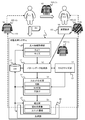
- FIG. 1 is an explanatory diagram showing the overall configuration of a garment production system 1 for individually producing garments (or clothes, etc.).
- the garment production system 1 is a system for producing a garment 100 that constitutes a garment according to a user's request.
- the garment production system 1 can produce a finished product of the garment 100, or can produce only the unit 110 that is a component of the garment 100, as in other embodiments described below. A detailed configuration example of the garment 100 will be described later in another embodiment.
- the garment production system 1 includes, for example, a basic information acquisition unit 11, a pattern data generation unit 12, a customization unit 13, a unit generation unit 14, an assembly unit 15, a shipping unit 16, and a database unit 17. Can do.
- the database is abbreviated as DB.
- the garment production system 1 does not necessarily include the assembly unit 15. This is because the garment 100 of the present embodiment is configured by connecting a plurality of units that can be easily assembled and disassembled, so that the garment 100 can be assembled outside the garment production system 1.
- the basic elements of the garment such as the best season, the sleeve, and the town are divided by a plurality of units 110 each. It is not necessary that all the basic elements constituting the garment are divided by the plurality of units 110, and the main elements (including at least the best season and sleeves) of the basic elements only need to be configured by the plurality of units 110. That is, “predetermined regions” indicate either basic elements of clothing or major elements of basic elements of clothing.
- each unit 110 is generated according to the user's order, and the generated units 110 are connected by the fasteners 120 according to a predetermined arrangement, thereby individually producing the garment 100 according to the user's request. can do.
- the user may desire a partial change in the configuration of the garment 100 by sending the change request information D2 to the garment production system 1 at a later date.
- the clothes 100 (1) are given to the clothes before the configuration change
- the clothes 100 (2) are given the clothes after the structure change.
- it does not ask before and after a structure change, it calls the clothing 100.
- the user who ordered the clothing 100 (1) and the user who requests the configuration change (customization) of the clothing (1) are the same user U1.
- the user U1 who is the orderer of the garment 100 (1) before the configuration change and the user U2 requesting the configuration change may be different, as in other embodiments described later.
- the basic information acquisition unit 11 acquires, from the user, basic information D1 including data related to the user and type information for designating a predetermined clothing type (S1).
- the data related to the user includes, for example, size data such as height and chest circumference in addition to bibliographic items such as the user's name, address, and contact address.
- the type information is information for designating the type of the garment 100 having a structure unique to the present embodiment, and is selected from types prepared in advance, such as shirts, jackets, pants, dresses, and skirts.
- the size of each part of the user's body can be measured by, for example, a stationary scanner or a handy scanner, a camera, an ultrasonic measurement device, and the like, and can be input to the garment production system 1 as electronic data.
- a sheet for entering a numerical value of the size may be prepared, and the value written on the sheet may be input to the garment production system 1 by character recognition with a camera or the like.
- the salesperson may manually measure and read the size of each part of the user's body, and the result of automatically recognizing the read voice may be input to the clothing production system 1.
- the pattern generation unit 12 generates pattern data of each unit 110 that constitutes each region of the clothing 100 designated by the user based on the basic information D1 acquired by the basic information acquisition unit 11 (S2).
- the customization unit 13 can customize the color and material of the unit when generating the pattern data (S3).
- the customization operation may be performed by the user himself / herself, or may be performed by a salesperson or the like while listening to the user's request.
- the material of all the units 110 may be the same, or the material may be different for each unit.
- the unit generation unit 14 generates each unit based on the pattern data generated by the pattern data generation unit 12 (S4). For example, the unit generation unit 14 stacks the selected material, adds an identification number to the cut material, and makes a hole at a predetermined position.
- the unit generation unit 14 can include, for example, a laser processing machine, a laser printer, a 3D printer, and the like.
- the identification number is information for uniquely determining the position of the unit 110 in the garment 100.
- the identification number may be printed on the unit 110 so that it can be visually confirmed, or may be added to the unit 110 in a form that can be detected by infrared rays or ultraviolet rays.
- a configuration may be adopted in which a memory element in which information is written is embedded in the unit 110 and an identification number is read from the memory element by using RFID technology or the like.
- the assembling unit 15 assembles the clothes 100 by connecting the units generated by the unit generating unit 14 to a predetermined arrangement.
- the assembling unit 15 prepares the fastener 120, and connects the adjacent units with the prepared fastener 120 (S5).
- the fastener 120 connects the unit 110 so that it can be assembled and disassembled manually. Therefore, the assembly unit 15 may be excluded from the garment production system 1.
- the shipping unit 16 tags the clothes 100 assembled by the assembling unit 15, packs them, creates a shipping slip, and prepares for shipping, and then ships the clothes 100 to a predetermined destination (S ⁇ b> 6). ).
- the predetermined destination is the user U1 who is the orderer of the clothes 100.
- the clothes shipped toward the user U1 are referred to as clothes 100 (1).
- the user U1 may desire to change the design of the clothes 100 (1) according to a change in taste, a change in fashion, or the like (S7).
- the user U1 transmits the change request information D2 to the garment production system 1 and sends the garment 100 (1) to be changed to the garment production system 1 (S8).
- the pattern data generation unit 12 generates pattern data corresponding to the change requested by the user based on the change request information D2 (S2).
- the unit generator 14 generates a unit 110 corresponding to the change based on the pattern data corresponding to the change (S4).
- the assembling unit 15 assembles the garment 100 (2) with a new design by incorporating the new unit 110 into the garment 100 (1).
- the clothing 100 (2) whose design configuration has been changed is shipped from the shipping unit 16 toward the user U1 (S9).
- User U1 sends the existing garment 100 (2) and request change request information D2 to the garment production system 1 (S8) when he / she wishes to change the design further.
- the garment 100 (2) becomes the garment before the configuration change.
- reference numeral 100 (3) can be given to clothes that have undergone two design changes (not shown).
- pattern data of each unit 110 constituting each area of the garment 100 is generated based on the user-related data including the user size data and the type information. However, the type information and the size of the type are generated. Based on the information, pattern data of each unit 110 constituting each region of the clothing 100 may be generated. That is, each unit 110 may be generated based on a prescribed size for each type of garment 100 to produce a large number of ready-made garments.
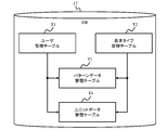
- the database unit 17 includes, for example, a user management table T1, a basic type management table T2, a pattern data management table T3, and a unit data management table T4.
- the user management table T1 manages data related to users.
- the data related to the user can include, for example, the user's nomination, address, contact address, size data, settlement information, purchase history of the clothing 100, and the like.
- the basic type management table T2 manages the basic types of the clothes 100. In addition to the basic type shape, the material type and size classification may be included.
- the pattern data management table T3 manages the pattern data of each unit 110 constituting the clothes ordered by the user.
- the unit data management table T4 manages, for example, the manufacturing date, identification number, history, etc. of each unit 110.
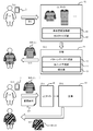
- FIG. 3 shows an example of how to use the garment production system 1.
- the garment production system 1 is distributed and arranged in a website (EC site) 18 and a factory 19.
- EC site 18 accesses EC (Electronic Commerce) site 18 linked with clothing production system 1 by using user terminal 2 such as a smartphone, for example.
- the EC site 18 includes a basic information acquisition unit 11 and a customization unit 13.
- the user inputs basic information D1 from the user terminal 2 to the basic information acquisition unit 11 (S11). Furthermore, the user can also change the basic type design by inputting to the customization unit 13 from the user terminal 2.
- the factory 19 includes, for example, a pattern data generation unit 12, a unit generation unit 14, and an assembly unit 15. Although illustration is omitted, the factory 19 may include a shipping unit 16.
- the factory 19 generates pattern data of each unit 110 based on the basic information D1 passed from the EC site 18, generates each unit 110 from the pattern data, and assembles each unit 110 to garment 100 (1 ) Is produced (S12).
- the factory 19 sends the produced clothing 100 (1) to the user U1 who is the orderer (S13).
- User U1 wears clothes 100 (1) and enjoys for a while, but fashion, taste, lifestyle, etc. change with time.
- the user U1 who wishes to change the design accesses the EC site 18 using the user terminal 2 and inputs the change request information D2 to the EC site 18, thereby changing the design of the garment 100 (1) currently owned.
- a request is made (S15).
- the clothes 100 (1) to be changed are sent to the factory 19 (S15).
- the factory 19 recreates the garment 100 (1) into the garment 100 (2) by recreating at least a part of the pattern data based on the change request information D2 and newly creating the unit 110 (S16).
- the remade clothing 100 (2) is shipped from the factory 19 to the user U1 (S17).
- the pattern data of each unit 110 that constitutes each predetermined area included in the garment 100 is generated, and each unit 110 is generated based on the pattern data.
- the change request information D2 for requesting the change of the unit of the copy is acquired, the pattern data corresponding to the change is generated based on the change request information D2, and the change is supported based on the pattern data corresponding to the change Since the unit 110 to be generated is generated, it is possible to produce the garment 100 that can meet the detailed demands of the user.
- the predetermined area such as the best time is composed of a plurality of units, it is possible to produce clothes having a design that meets the detailed requirements of the user. Furthermore, according to the present embodiment, some of the units can be changed later, and it is possible to follow a change in user's preference, a change in fashion, and the like, and the convenience of the user can be improved.
- the environment-friendly garment 100 can be produced.
- the design of the clothes 100 can be changed without using a special device such as a sewing machine, the user can change the design of the clothes 100 by changing the unit 110 at home or the like. Can be changed, and the usability is improved.
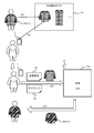
- FIG. 4 is an explanatory diagram showing a method of using the garment production system 1.
- User U1 registers clothes 100 (1) in a website 18a such as a secondhand sales site and tries to sell them (S21).
- the website 18a may be a clothes exchange site or a site operated by the user U1 individually. Any means may be used as an opportunity for the owner of the garment 100 (1) to change from the user U1 to another user U2. Therefore, the user U1 may sell the clothing 100 (1) at a so-called flea market or exhibit it at a bazaar without going through the website 18a.
- User U2 accesses website 18a via user terminal 2 and purchases clothing 100 (1) (S22). Alternatively, the user U2 obtains the clothes 100 (1) at an actual second-hand goods store or a flea market.
- a tag 109 (see FIG. 8) is attached to the garment 100 (1) as described later.
- Identification information (ID) for identifying the owner user is added to the tag 109.
- the user ID may be printed in a readable form, or may be added in a form that cannot be read by a normal person such as a barcode.
- User U2 reads the user ID of the acquired garment 100 (1) via the user terminal 2, and transmits it together with the basic information D1 and the change request information D2 to the factory 19a constituting the garment production system 1a (S23). Furthermore, the user U2 sends the acquired clothes 100 (1) to the factory 19a (S23).
- the basic information D1 includes, for example, information such as the name and address of the user U2 and size data of each part of the body of the user U2.
- the user U2 can separately acquire the size of the user U2 by using a size data acquisition device such as a camera provided in the user terminal 2 or a scanner device installed in a store or the like.
- the change request information D2 can include information on the design change (including size change) of the garment 100 (1) and information for requesting registration of owner change.
- the factory 19a changes the design of the garment 100 (1) based on the basic information D1 and the change request information D2 received from the user U2 (S24).
- the factory 19a changes the user ID added to the tag 109 from the ID of the user U1 to the ID of the user U2, and updates the stored content of the database unit 17 (S24).
- the factory 19a sends the clothes 100 (2) tailored based on the designation from the user U2 to the user U2 (S25).
- This embodiment which is configured in this way, also has the same function and effect as the first embodiment. Furthermore, according to the present embodiment, even when the clothes 100 (1) are transferred from one user U1 to another user U2, the unit 110 prepared for the original user U1 is effectively used to create a new user U2. Can be produced efficiently.
- FIG. 5 is an explanatory diagram of the garment production system 1b according to the present embodiment.
- the garment production system 1b includes a mobile factory section (also called a mobile factory) 3.
- the mobile factory 3 includes, for example, a mobile factory main body 31, a processing device 32 provided in the mobile factory main body 31, and a computer 33.
- the computer 33 stores, for example, control programs for the basic information acquisition unit 11, the pattern data generation unit 12, the customization unit 13, and the unit generation unit 14.
- the processing device 32 includes a processing machine portion (for example, a laser processing machine) of the unit generation unit 14.
- the processing device 32 may include at least a part of the configuration of the assembly unit 15, for example, a robot that attaches the fastener 120 to the unit 110.
- the computer 33 can acquire the size of each part of the body of the user U1 by using the size data acquisition device 34 such as a scanner or a camera (S31).
- the size data acquisition device 34 may be a device attached to the mobile factory 3, or a smartphone or the like possessed by the user U1 or a salesperson.
- the computer 33 When the computer 33 acquires the basic information D1 such as the size data and the clothes type desired by the user, the computer 33 generates pattern data and sends control data to the processing apparatus (S32).
- the processing device 32 produces the unit 110 based on the control data (S33).
- Each produced unit 110 is assembled outside the mobile factory 3.
- the processing device 32 has an assembly function, the assembly process may be performed in the mobile factory 3. Alternatively, the user can take the completed units 110 and the fasteners 120 home and assemble them by themselves.
- This embodiment which is configured in this way, also has the same function and effect as the first embodiment. Furthermore, in the present embodiment, since the garment production system 1b is configured as the mobile factory 3 configured to be movable or portable, the garment 100 can be manufactured and sold at an arbitrary place, and usability is improved. Furthermore, by bringing the mobile factory 3 to a small store, it is possible to produce and sell strict couture and made-to-order products on the spot.
- the senor 160 is built in the unit 110 or the fastener 120 constituting the garment 100.
- a reference numeral 110 ⁇ / b> S is given to a unit incorporating the sensor 160
- a reference numeral 120 ⁇ / b> S is given to a fastener incorporating the sensor 160.
- the sensor 160 is configured as a sensor that can detect data related to the body of the user wearing the clothing 100, such as a body temperature sensor, a pulse sensor, a vibration sensor, a pressure sensor, and the like. Or sensor 160 may be constituted as a sensor which measures the external environment of clothes 100, such as outside temperature, humidity, and the amount of solar radiation.
- the garment 100 can also include an internal environment sensor that detects the internal environment of the garment 100 (user's biological information) and an external environment sensor that detects the external environment of the garment 100.
- These sensors include, for example, a measurement unit, a transmission unit that sends information measured by the measurement unit to the outside, and a power supply unit (all not shown).
- the power supply unit may be, for example, a battery, a small power generator that generates electricity at body temperature, or a device that converts electromagnetic waves input from the outside into electric power.
- Information is collected by the data collection device 41 of the sensor 160 built in the unit 110S or the fastener 120S. Information collected from each sensor 160 is sent to the data analysis system 42.
- the data collection device 41 may be configured as a so-called wearable terminal such as a wristwatch type, a bracelet type, an anklet type, a pendant type, a necklace type, a collar type, a glasses type, a hat type, or a smartphone. It may be configured as a portable information terminal.
- the data analysis system 42 executes a predetermined data analysis process based on the information of each sensor 160 received from the data collection device 41 and outputs the result. For example, the data analysis system 42 can estimate the user's health condition or estimate the user's mood, and send the estimation result to a smartphone or the like possessed by the user.
- the sensor 160 can be built in the unit 110S or the fastener 120S, and therefore the sensor 160 can be arranged at a predetermined position of the garment 100. Thereby, a user's health condition etc. can be analyzed and the convenience improves.
- FIG. 7 is an explanatory diagram of this embodiment.
- the user can inquire about the history of the clothing 100 in units.
- the unit history inquiry unit 51 When an inquiry request is input from the user terminal 2 such as a smartphone held by the user, the unit history inquiry unit 51 generates a unit history inquiry screen G1 corresponding to the inquiry request and transmits it to the user terminal 2 (S41). .
- the inquiry request includes, for example, a user ID.
- the clothing ID may be included in the inquiry request.
- the unit history inquiry unit 51 is a device or a computer program that can use the database unit 17.
- the unit history inquiry unit 51 searches the database unit 17 and acquires information requested from the user terminal 2 (S42).
- the unit history inquiry part 51 produces
- the unit history inquiry screen G1 can include, for example, a unit history list display portion GP11 and a clothing image display portion GP12 corresponding to the unit history.
- the list display portion GP11 can have items such as “area”, “unit ID”, and “history”.
- “Area” is an area to which the unit 110 belongs among the basic elements of the garment 100.
- the “unit ID” is identification information that uniquely identifies the unit 110.
- “History” is information relating to the history of the unit 110, for example, the date and time when the unit was generated, the location where the unit was generated, the transition of the user ID that is the owner of the unit, the frequency of replacement, and the material before replacement There are various types.
- the user can sell the clothing 100 formed by connecting the units 110 on a website or the like, and can also sell the unit 100 on a unit basis.
- the user can also make a new garment 100 by connecting the units 110 collected here and there with the fasteners 120.
- This embodiment which is configured in this way, also has the same function and effect as the first embodiment. Further, in the present embodiment, the user can inquire about the history of each unit 110 constituting the clothes 100 that the user owns or the clothes 100 to be purchased. For this reason, according to the present embodiment, the user can confirm the origin of each unit 110 constituting the garment 100, and convenience is improved.
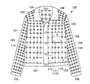
- FIG. 8 is a schematic diagram of the garment 100 according to the present embodiment.
- FIG. 8 is a schematic diagram of the garment 100 according to the present embodiment.
- the garment 100 includes a front body part 101, a back part 102, a sleeve part 103, a collar part 104, a placket part 105, a pocket part 106, a hem part 107, and a cuff part. 108 and a tag 109.
- Each part is configured to be detachable by a fastener 120 described later with respect to an adjacent part.
- the tag 109 describes information associated with the user ID or the user. Note that identification information (user ID) may not be added to the tag 109.
- the front body part 101, the back part 102, and the sleeve part 103 are composed of a plurality of units (pieces) 110 and a plurality of fasteners 120.
- Each unit 110 is made of materials such as cotton, wool, nylon, leather, fur, synthetic fiber, silk, plastic, and metal.
- Each unit 110 basically has a shape that does not depend on the position on the clothes 100, the shape of the clothes 100, and the like. In the present embodiment, the unit 110 is mostly rectangular but may be any shape that includes four sides. .
- Each unit 110 may have a triangular shape or other polygonal shapes. Or the shape containing a curve may be sufficient.
- the material may be used as a material (fabric) by processing materials other than used clothes and clothes.
- Each unit 110 has a front surface 111 and a back surface 112 (see FIG. 12).
- An identification number 113 indicating the position of each unit 110 in the garment 100 is attached to the surface 111 of each unit 110.
- the identification number 113 is attached
- a first through hole 114 is formed at each corner of each unit 110.
- Each unit 110 may not have the identification number 113 attached.
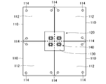
- FIG. 9 is a plan view showing a state in which adjacent units 110 are connected by a fastener 120.
- FIG. 10 is an exploded perspective view of the pin 141 and the pressing member 142 of the connecting portion 140.
- FIG. 11A is a plan view of the pressing member 142
- FIG. 11B is a side view of the pressing member 142 of FIG. 11A viewed from the right side
- FIG. 11C is a side view of the pressing member 142 of FIG. FIG.
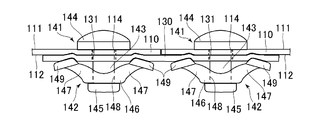
- FIG. 12 is a side view showing a state in which adjacent units 110 are connected by a fastener 120.
- the fastener 120 includes a connection base 130 and a plurality (four in this embodiment) of connection parts 140.
- connection base 130 is made of a material having flexibility and excellent tensile strength, such as felt, leather, or the same material as the unit 110. As shown in FIG. 12, a plurality of second through holes 131 are formed in the connection base 130. The diameter of the second through hole 131 is substantially equal to the diameter of the first through hole 114.
- Each connecting portion 140 is made of a flexible material such as a resin material, and includes a pin 141 and a pressing member 142.
- the pin 141 includes, for example, a shaft 143, a front projection 144 provided at one end of the shaft 143, and a back projection 145 provided at the other end of the shaft 143.
- the front protrusion 144 corresponds to a “first contact portion”
- the back protrusion 145 corresponds to a “second contact portion”.
- the diameter of the shaft 143 is configured to be slightly smaller than the diameter of the first through hole 114 and the diameter of the second through hole 131.
- the front projection 144 has a substantially dome shape, and the diameter of the first through hole 114 and the second through hole 131 are such that the diameter does not pass through the first through hole 114 and the second through hole 131. It is configured to be sufficiently larger than the diameter.
- the back protrusion 145 has a substantially disk shape, and its diameter is slightly larger than the diameter of the first through hole 114 and the second through hole 131, and the first through hole 114 and the second through hole 131 are formed. It is configured to pass.
- the pressing member 142 includes a base 146 and a pair of pressing portions 147.
- the base portion 146 has a substantially annular shape having a third through hole 148.
- the diameter of the third through hole 148 is smaller than the diameter of the back projection 145 and is configured to be substantially the same as the diameter of the shaft 143.
- the second pressing portions 147 are provided at positions facing each other in the radial direction of the base portion 146, and extend so as to be separated from each other as the distance from the base portion 146 increases.
- a semi-cylindrical (fan-shaped) pressing piece 149 is provided at the tip of each pressing portion 147.
- a slit 150 is formed that extends to the middle of each pressing portion 147 along the thickness direction of the base 146. Each slit 150 communicates with the third through hole 148.
- the assembly work may be performed by a person such as a factory worker, a store salesperson, or a user, or may be performed by a robot.
- a subject that performs the following assembly method is called a work subject.
- the worker may be a human or a machine.
- the work subject arranges a plurality of units 110 to be connected to each other based on the identification number 113 so that the sides are adjacent to each other.
- the work subject is arranged on the back surface 112 of the plurality of units 110 arranged adjacent to each other so that the connection base 130 of the fastener 120 extends over the units 110 arranged adjacent to each other.
- the second through hole 131 of the connection base 130 and the first through hole 114 of each unit 110 are opposed to each other.
- the work subject passes the pin 141 of the connecting portion 140 through the first through-hole 114 and the second through-hole 131 from the surface 111 side of the plurality of units 110, and the front projection 144 is placed on the surface of the unit 110. It is made to contact 111.
- the work subject presses the pair of pressing parts 147 toward the connection base 130 side while the pair of pressing parts 147 are located closer to the connection base 130 side than the base part 146 while the work main body presses the base member 146.
- the pressing pieces 149 of the pair of pressing portions 147 are in contact with the connection base 130, and the pair of pressing portions 147 are spread apart so as to be connected to each other while having an elastic force.
- the base 130 is pressed. Thereby, the unit 110 and the connection base 130 are clamped by the connection part 140.
- four adjacent units 110 can be connected to each other by attaching connecting portions 140 at four locations.
- the work subject can repeatedly create the garment 100 by repeating the assembly process.
- the work subject when releasing the connection of the plurality of units 110, deforms the third through hole 148 and the slit 150 so as to spread while pulling one of the pair of pressing portions 147, and then presses the pressing portion 147.
- the pin 141 is removed from the back protrusion 145.
- the work subject removes the pin 141 from the first through hole 114 and the second through hole 131, thereby releasing the connection of the plurality of units 110.
- the garment 100 includes the plurality of units 110 and the fastener 120 for connecting the plurality of units 110, and the plurality of fasteners 120 are provided on the back surface 112 side of the plurality of units 110.
- a plurality of connecting portions 140 that connect the plurality of units 110 and the connecting base 130 to each other.
- the connecting part 140 includes a pin 141 and a pressing member 142.
- the pin 141 includes a shaft 143 that passes through the unit 110 and the connection base 130, a front projection 144 that is provided at one end of the shaft 143 and abuts against the surface 111 of the unit 110, and a back projection provided at the other end of the shaft 143. Part 145.
- the pressing member 142 has a third through hole 148 through which the pin 141 passes, a base portion 146 that is located on the connection base 130 side with respect to the back projection portion 145 and abuts the back projection portion 145, and a connection base 130 with respect to the base portion 146. And a pair of pressing portions 147 that press the connection base 130 at a position sandwiching the pin 143 on the side.
- the units 110 can be recombined many times, and various patterns, shapes, and materials can be freely combined in a single textile, and clothes 100 that match the user's body shape and preferences can be easily provided. can do.
- the plurality of units 110 can be easily connected or separated by the fastener 120 constituted by the connection base 130 and the connection part 140, the user can assemble and reassemble the clothing 100.
- the fastener 120 can be reused.
- the base portion 146 is formed with a pair of slits 150 extending from the opposite side of the position where the pressing portions 147 are provided toward the pressing portions 147 toward the pressing portions 147 and communicating with the third through holes 148. ing. Thereby, since the 3rd through-hole 148 can be easily expanded by a pair of slit 150, the press member 142 can be easily attached to the pin 141, or can be removed from the pin 141.
- the first through hole 114 and the second through hole 131 may not be through holes, and may be slits or cross-shaped cuts, for example.
- the front protrusion 144 may not be a dome shape, and may be any shape as long as it does not pass through the first through hole 114 such as a cross shape.
- FIG. 13 is a schematic diagram of a garment 200 according to the present embodiment.
- the garment 200 includes a front body part 201, a back part 202, a sleeve part 203, a collar part 204, a skirt part 205, and a tag 206.
- Each part is configured to be detachable with a fastener 220 described later with respect to adjacent parts.
- the tag 206 describes a user ID or information associated with the user.
- the front body part 201, the back part 202, and the sleeve part 203 are composed of a plurality of units (pieces) 210 and a plurality of fasteners 220.
- the material, shape, and the like of each unit 210 are basically the same as those of the unit 110 of the sixth embodiment, but a part of the unit 210 of the present embodiment has a shape that depends on the shape of the garment 200.
- each unit 210 is formed with a plurality of first connection holes 211 and a plurality of second connection holes 212 arranged in two rows along each side of the rectangular shape.
- the plurality of second connection holes 212 are formed inside the plurality of first connection holes 211 at a predetermined interval.
- FIG. 14 for simplification of the drawing, only one first connection hole 211 and one second connection hole 212 on each side of some units 210 are given identification numbers.
- the two units 210 to be connected to each other are connected by the fastener 220 with the side of one unit 210 and the side of the other unit 210 folded and overlapped.
- the second unit 210 is formed on the side of the one unit 210.
- the two connection holes 212 are formed more inside than the second connection holes 212 formed on the side of the other unit 210.
- a second connection hole 212 indicated by a broken line on the right side of the unit 210 shown in FIG. 14 indicates the second connection hole 212 formed on the side of one unit 210 arranged on the inner side.
- the fastener 220 includes a pin 221 and a fitted member 222.
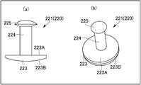
- FIG. 15A is a side view of the pin 221 of the fastener 220, and FIG. 15B is a perspective view of the pin 221.
- FIG. 15B is a perspective view of the pin 221.
- FIG. 16A is a plan view of the insertion member 222 of the fastener 220
- FIG. 16B is a perspective view of the insertion member 222.
- the pin 221 is made of a resin material (for example, nylon). As shown in FIG. 15, the pin 221 includes a substantially disk-shaped pin base portion 223 constituted by a flat surface 223A and a spherical surface 223B, a shaft 224 extending from the center portion of the pin base portion 223 on the flat surface 223A side, and the tip of the shaft 224. And a fitting portion 225 provided in the.
- the fitting portion 225 has a substantially oval shape, and the diameter (major axis) is larger than the diameter of the shaft 224. Further, the length of the shaft 224 is set according to the thickness of the unit 210.
- the fitted member 222 has a substantially disk shape and is made of a flexible material such as a resin material (for example, ABS resin).
- the insertion member 222 includes an insertion base portion 226 having an annular shape, and a plurality (eight in this embodiment) of insertion pieces 227 provided on the inner periphery of the insertion base portion 226. Note that the number of the inserted pieces 227 is not limited to eight.
- Each inserted piece 227 is provided on the inner periphery of the inserted base portion 226 at equal intervals along the circumferential direction, protrudes inward from the inner periphery of the inserted base portion 226, and forms a cantilever shape. Yes. Therefore, a gap 229 is formed between the adjacent insertion pieces 227.
- the plurality of insertion pieces 227 form insertion insertion holes 228 into which the insertion portions 225 are inserted by the inner end portions thereof, and expand and contract the insertion insertion holes 228 by elastic deformation. In FIG. 16, for simplification of the drawing, only one inserted portion 227 is given an identification number.
- each insertion piece 227 inclines so that it may approach the insertion part 225 as it goes inward in the state with which the pin 221 was mounted
- each inserted piece 227 has a first inclined surface 227A that inclines so as to approach the insertion portion 225 toward the pin base portion 223 side in the state where the insertion piece 227 is attached to the pin 221.
- the second inclined surface 227B is inclined so as to approach the pin base 223 as it goes inward.
- the radial length of the second inclined surface 227B is configured to be shorter than the radial length of the first inclined surface.
- the diameter of the insertion portion 225 of the pin 221 is configured to be longer than the diameter of the insertion hole 228 of the insertion member 222.
- the assembly work may be performed by a person such as a factory worker, a store salesperson, or a user, or may be performed by a robot.
- a subject that performs the following assembly method is called a work subject.
- the worker may be a human or a machine.
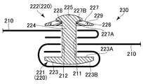
- FIG. 17 is a cross-sectional view showing a connecting structure 230 of the units 210 in which the two units 210 are connected by the fasteners 220.
- the work subject arranges the units 210 to be connected to each other so that the sides are adjacent to each other.
- the work subject causes the fitting portion 225 of the pin 221 and the shaft 224 to pass through the first connection hole 211 of the unit 210 located on the inner side (body side) in the state of becoming the garment 200 among the adjacently arranged units 210.
- the unit 210 has front and back sides, the fitting portion 225 of the pin 221 and the shaft 224 are passed through from the back side to the front side.
- the unit 210 covers the flat surface 223A of the pin base 223.
- the unit 210 is wound so as to cover the spherical surface 223 ⁇ / b> B of the pin base portion 223, and the fitting portion 225 of the pin 221 and the shaft 224 are passed through the second connection hole 212.
- the first unit 210 has the first communication hole 211 positioned closer to the pin base 223 than the second connection hole 212, and the first unit 210 A portion between the first communication hole 211 and the second connection hole 212 covers the outer periphery of the pin base portion 223 and the side (cut edge) of one unit 210 so that the first connection hole 211 and the second connection hole 212
- the shaft 224 and the fitting portion 225 are penetrated and attached to the pin 221.
- the other unit 210 has the first connection hole 211 in a state in which the first communication hole 211 is located closer to the one unit 210 than the second connection hole 212.
- the shaft 224 and the fitting portion 225 are penetrated through the second connecting hole 212 and attached to the pin 221.
- the insertion portion 225 is inserted into the insertion hole 228 of the insertion member 222, and the two units 210 are sandwiched by the pin base portion 223 and the insertion member 222 and connected to each other. In this way, the connection structure 230 of the units 210 shown in FIG. 17 is formed. Then, the garment 200 can be created by the work subject repeatedly performing the assembly process in the adjacent units 210.
- the units 210 can be rearranged many times, and various patterns, shapes, and materials can be freely combined in a single textile, and the clothes 200 that match the user's body shape and preferences can be easily provided. can do.
- the plurality of units 210 can be easily connected or separated by the fastener 220, the user can assemble and reassemble the garment 200, and the unit 210 and the fastener 220 can be reused.
- the fastener 220 includes a pin 221 and a fitting member 222.
- the pin 221 has a pin base 223, a shaft 224, and a fitting portion 225, and the fitting member 222 has an annular shape.
- the insertion base 226 has a plurality of insertion pieces 227 provided on the inner periphery of the insertion base 226. The plurality of insertion pieces 227 are inserted into the insertion portions 225 by their inner ends.
- the insertion hole 228 is formed, and the insertion hole 228 is enlarged or reduced by elastic deformation. That is, the pin 221 and the inserted member 222 are connected by snap fit. Therefore, the pin 221 and the insertion member 222 can be firmly connected and can be easily connected or separated. As a result, the connection of several units 210 can be stabilized and the intensity
- connection structure 230 of the unit 210 the portion between the first communication hole 211 and the second connection hole 212 of the unit 210 covers the outer periphery of the pin base portion 223 and the side (edge edge) of one unit 210. Since it is configured, it is possible to prevent the pin 221 from being exposed to the back side, and the cutting edge of the unit 210 from being exposed to the outside. Therefore, the comfort of the garment 200 can be improved.
- the eighth embodiment will be described with reference to FIGS.
- the fastener 320 since the configuration of the fastener 320 is different from that of the garment 200 described in the seventh embodiment, the configuration of the fastener 320 will be described.
- the fastener 320 includes a pin 321 and a fitted member 322.
- FIG. 18A is a side view of the pin 321 of the fastener 320
- FIG. 18B is a perspective view of the pin 321.
- FIG. 18A is a side view of the pin 321 of the fastener 320
- FIG. 18B is a perspective view of the pin 321.
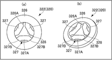
- FIG. 19A is a plan view of the inserted member 322 of the fastener 320
- FIG. 19B is a perspective view of the inserted member 322.
- the pin 321 includes a substantially disc-shaped pin base portion 323 constituted by a flat surface 323A and a spherical surface 323B, a shaft 324 extending from the center portion of the pin base portion 323 on the flat surface 323A side, And a fitting portion 325 provided at the tip of the shaft 324.
- the fitted member 322 has a substantially disk shape and is made of a flexible material such as a resin material (for example, ABS resin).
- the insertion member 322 includes an insertion base portion 326 having an annular shape, and a plurality of (three in this embodiment) insertion pieces 327 provided on the inner periphery of the insertion base portion 326.
- Each inserted piece 327 is provided on the inner peripheral surface 326A of the inserted base 326 at equal intervals along the circumferential direction.
- Each inserted piece 327 includes a central portion 327A provided apart from the inner peripheral surface 326A, and a connecting portion 327B extending from both ends of the central portion 327A toward the inner peripheral surface 326A and connected to the inner peripheral surface 326A.
- Have Adjacent connecting portions 227B are separated from each other in the circumferential direction.
- FIG. 19 for simplification of the drawing, only the center part 327 ⁇ / b> A and the connection part 327 ⁇ / b> B of one insertion part 227 are given identification numbers.
- the central portion 327A of the three insertion pieces 327 is provided so as to form a substantially equilateral triangle shape, and the insertion holes 328 having a substantially equilateral triangular shape are formed by the three central portions 327A.
- the insertion hole 328 is configured such that the diameter of the maximum circle that can be inserted is longer than the diameter of the shaft 324 and shorter than the diameter of the insertion portion 325.
- the assembly of the plurality of units 210 is performed in the same manner as in the seventh embodiment, and as shown in FIG. 20, a connecting structure 330 of the units 210 is formed by connecting the two units 210 with the fasteners 320.
- the fastener 320 it is possible to provide the fastener 320, the connecting structure 330 of the unit 210, and the garment 200 that have the same effects as in the seventh embodiment.
- the shapes of the fasteners 220 and 320 are not limited to the shapes shown in the seventh and eighth embodiments.
- the fastener corresponds to the pin bases 223 and 323 of the pins 221 and 321, a base having a part longer than the diameter of the first communication hole 211, the shafts 224 and 324 and the fitting parts 225 of the pins 221 and 321, 325, a penetrating portion extending from the base portion and penetrating the first communication hole 211 and the like, and corresponding to the fitted members 222 and 322, provided in a portion protruding from one unit 210 of the penetrating portion.
- the structure provided with the fastening part which has a part longer than the diameter of the communicating hole 212 may be sufficient.
- the said fastening part may be comprised integrally with respect to the penetration part, and may be comprised separately so that attachment or detachment is possible.
- this invention is not limited to the above-mentioned embodiment, Various modifications are included.
- the above embodiment has been described in detail for easy understanding of the present invention, and is not necessarily limited to the one having all the configurations described.
- a part of the configuration of one embodiment can be replaced with the configuration of another embodiment.
- the configuration of another embodiment can be added to the configuration of a certain embodiment.
- another configuration can be added, deleted, or replaced.
- the above components, functions, processing units, processing means, etc. may be realized in hardware by designing some or all of them, for example, with an integrated circuit.
- Each of the above-described configurations, functions, and the like may be realized by software by interpreting and executing a program that realizes each function by the processor.
- Information such as programs, tables, and files for realizing each function can be stored in a recording device such as a memory, a hard disk, an SSD (Solid State Drive), or a recording medium such as an IC card, an SD card, or a DVD.
Landscapes
- Engineering & Computer Science (AREA)
- Physics & Mathematics (AREA)
- Geometry (AREA)
- Theoretical Computer Science (AREA)
- General Physics & Mathematics (AREA)
- Computer Hardware Design (AREA)
- Evolutionary Computation (AREA)
- General Engineering & Computer Science (AREA)
- Textile Engineering (AREA)
- Human Computer Interaction (AREA)
- Architecture (AREA)
- Computational Mathematics (AREA)
- Mathematical Analysis (AREA)
- Mathematical Optimization (AREA)
- Pure & Applied Mathematics (AREA)
- Professional, Industrial, Or Sporting Protective Garments (AREA)
- Slide Fasteners, Snap Fasteners, And Hook Fasteners (AREA)
- General Factory Administration (AREA)
- Management, Administration, Business Operations System, And Electronic Commerce (AREA)
- Outerwear In General, And Traditional Japanese Garments (AREA)
Abstract
L'invention concerne un système de production de vêtement et un procédé de commande conçu pour permettre une production efficace de vêtements en fonctions des désirs des utilisateurs. Un système de production de vêtement 1 comprend : une section d'acquisition d'informations de base 11 pour acquérir des informations de base D1 comprenant des données relatives à l'utilisateur et des informations de type spécifiant le type d'un vêtement donné 100 ; une section de génération de données de modèle 12 pour générer des données de modèle pour les unités respectives 110 qui conçoivent chaque région donnée du vêtement donné sur la base des informations de base ; et une section de génération d'unité 14 pour générer chaque unité sur la base des données de modèle.
Applications Claiming Priority (2)
| Application Number | Priority Date | Filing Date | Title |
|---|---|---|---|
| JP2018-027595 | 2018-02-20 | ||
| JP2018027595A JP2022137314A (ja) | 2018-02-20 | 2018-02-20 | 衣服生産システム、その制御方法および衣服 |
Publications (1)
| Publication Number | Publication Date |
|---|---|
| WO2019163380A1 true WO2019163380A1 (fr) | 2019-08-29 |
Family
ID=67687648
Family Applications (1)
| Application Number | Title | Priority Date | Filing Date |
|---|---|---|---|
| PCT/JP2019/002089 Ceased WO2019163380A1 (fr) | 2018-02-20 | 2019-01-23 | Système de production de vêtement, procédé de commande associé, procédé de connexion d'unité et vêtement |
Country Status (2)
| Country | Link |
|---|---|
| JP (1) | JP2022137314A (fr) |
| WO (1) | WO2019163380A1 (fr) |
Cited By (1)
| Publication number | Priority date | Publication date | Assignee | Title |
|---|---|---|---|---|
| CN118452581A (zh) * | 2024-04-30 | 2024-08-09 | 广州市星道实业有限公司 | 一种衣服片体的边缘轮廓识别方法 |
Citations (11)
| Publication number | Priority date | Publication date | Assignee | Title |
|---|---|---|---|---|
| JPS6188211U (fr) * | 1984-11-16 | 1986-06-09 | ||
| JPS6342208U (fr) * | 1986-09-08 | 1988-03-19 | ||
| JPH0329003U (fr) * | 1989-08-01 | 1991-03-22 | ||
| JPH0451209U (fr) * | 1990-09-06 | 1992-04-30 | ||
| JP3063463U (ja) * | 1998-12-16 | 1999-11-05 | 株式会社アイリス | 棒状突起に止め具を差し込むワンタッチ釦 |
| JP2000187683A (ja) * | 1998-03-11 | 2000-07-04 | Toray Ind Inc | 衣料・服飾品の製造方法および衣料・服飾品の製造支援装置 |
| JP2002191891A (ja) * | 2000-12-27 | 2002-07-10 | Brother Ind Ltd | 加工装置 |
| JP2002227006A (ja) * | 2001-02-01 | 2002-08-14 | Mayumi Kobayashi | リムーバブルパーツウエア |
| JP2009028182A (ja) * | 2007-07-25 | 2009-02-12 | Samkyung Co Ltd | スナップボタンにおけるプラスチック製雌型留め具 |
| JP4526569B2 (ja) * | 2008-02-27 | 2010-08-18 | 千穂 西 | 新しい衣服用ピース |
| JP2017226947A (ja) * | 2016-06-02 | 2017-12-28 | アディダス アーゲー | 衣料品を製造する方法およびシステム |
-
2018
- 2018-02-20 JP JP2018027595A patent/JP2022137314A/ja active Pending
-
2019
- 2019-01-23 WO PCT/JP2019/002089 patent/WO2019163380A1/fr not_active Ceased
Patent Citations (11)
| Publication number | Priority date | Publication date | Assignee | Title |
|---|---|---|---|---|
| JPS6188211U (fr) * | 1984-11-16 | 1986-06-09 | ||
| JPS6342208U (fr) * | 1986-09-08 | 1988-03-19 | ||
| JPH0329003U (fr) * | 1989-08-01 | 1991-03-22 | ||
| JPH0451209U (fr) * | 1990-09-06 | 1992-04-30 | ||
| JP2000187683A (ja) * | 1998-03-11 | 2000-07-04 | Toray Ind Inc | 衣料・服飾品の製造方法および衣料・服飾品の製造支援装置 |
| JP3063463U (ja) * | 1998-12-16 | 1999-11-05 | 株式会社アイリス | 棒状突起に止め具を差し込むワンタッチ釦 |
| JP2002191891A (ja) * | 2000-12-27 | 2002-07-10 | Brother Ind Ltd | 加工装置 |
| JP2002227006A (ja) * | 2001-02-01 | 2002-08-14 | Mayumi Kobayashi | リムーバブルパーツウエア |
| JP2009028182A (ja) * | 2007-07-25 | 2009-02-12 | Samkyung Co Ltd | スナップボタンにおけるプラスチック製雌型留め具 |
| JP4526569B2 (ja) * | 2008-02-27 | 2010-08-18 | 千穂 西 | 新しい衣服用ピース |
| JP2017226947A (ja) * | 2016-06-02 | 2017-12-28 | アディダス アーゲー | 衣料品を製造する方法およびシステム |
Cited By (1)
| Publication number | Priority date | Publication date | Assignee | Title |
|---|---|---|---|---|
| CN118452581A (zh) * | 2024-04-30 | 2024-08-09 | 广州市星道实业有限公司 | 一种衣服片体的边缘轮廓识别方法 |
Also Published As
| Publication number | Publication date |
|---|---|
| JP2022137314A (ja) | 2022-09-22 |
Similar Documents
| Publication | Publication Date | Title |
|---|---|---|
| Jones et al. | Wearable Bits: scaffolding creativity with a prototyping toolkit for wearable e-textiles | |
| Koo et al. | Design functions in transformable garments for sustainability | |
| US7398133B2 (en) | Matching the fit of individual garments to individual consumers | |
| US20100023426A1 (en) | Distributed matching system for comparing garment information and buyer information embedded in object metadata at distributed computing locations | |
| CN105527946A (zh) | 一种基于工业互联网的快速成衣系统及其方法 | |
| US20180253430A1 (en) | Tagging, Tracking, and Cataloging Articles of Clothing | |
| KR20150129597A (ko) | 커스텀 디자인 의류를 주문하기 위한 방법 및 장치 | |
| US20190378191A1 (en) | Information processing method, garment order reception management apparatus, and storage medium | |
| JP2013196553A (ja) | 衣服管理及びレコメンド装置 | |
| JP2020181278A (ja) | ファッション推薦サーバ、ファッション推薦システム、ファッション推薦方法およびファッション推薦プログラム | |
| Zakaria | Clothing for children and teenagers: anthropometry, sizing and fit | |
| CN205384500U (zh) | 一种基于工业互联网的快速成衣系统 | |
| JP2022137314A (ja) | 衣服生産システム、その制御方法および衣服 | |
| Au et al. | Design preferences and experience of older people's choice in fashion in Hong Kong | |
| Zakaria | Evaluation of fit and size | |
| IL268482B (en) | Size measurement device, management server, user terminal and size measurement system | |
| JP2015011631A (ja) | 電子機器 | |
| CN112914175A (zh) | 一种口罩及口罩生产方法 | |
| Özbek et al. | APPLICATION OF DEVELOPING CLOTHING RECOMMENDATION SYSTEM WITH ARTIFICIAL INTELLIGENCE TECHNIQUES | |
| Wilcox | Stitching and Sustainability: Understanding How Home Garment Makers Value Clothing | |
| Byeon et al. | Wearable Designs for Hair Designers with 3D Virtual Images and 3D Printed Models | |
| Cohen | Design and Testing of Connectors for Detachable Joining of E-Textiles to Rigid Electronics | |
| CN121961690A (zh) | 一种个性化服装定制管理系统 | |
| Wilcox et al. | A Value Framework for Clothing | |
| Schulz-Müllensiefen et al. | Uniqlo: A Case Study on Creating Market Share with Affordable and Timeless Designs |
Legal Events
| Date | Code | Title | Description |
|---|---|---|---|
| 121 | Ep: the epo has been informed by wipo that ep was designated in this application |
Ref document number: 19757217 Country of ref document: EP Kind code of ref document: A1 |
|
| NENP | Non-entry into the national phase |
Ref country code: DE |
|
| ENP | Entry into the national phase |
Ref document number: 2020501598 Country of ref document: JP Kind code of ref document: A |
|
| 122 | Ep: pct application non-entry in european phase |
Ref document number: 19757217 Country of ref document: EP Kind code of ref document: A1 |