WO2019163393A1 - Dispositif de transmission de puissance - Google Patents
Dispositif de transmission de puissance Download PDFInfo
- Publication number
- WO2019163393A1 WO2019163393A1 PCT/JP2019/002365 JP2019002365W WO2019163393A1 WO 2019163393 A1 WO2019163393 A1 WO 2019163393A1 JP 2019002365 W JP2019002365 W JP 2019002365W WO 2019163393 A1 WO2019163393 A1 WO 2019163393A1
- Authority
- WO
- WIPO (PCT)
- Prior art keywords
- power transmission
- transmission device
- piston
- accumulator
- range
- Prior art date
- Legal status (The legal status is an assumption and is not a legal conclusion. Google has not performed a legal analysis and makes no representation as to the accuracy of the status listed.)
- Ceased
Links
Images



Classifications
-
- F—MECHANICAL ENGINEERING; LIGHTING; HEATING; WEAPONS; BLASTING
- F16—ENGINEERING ELEMENTS AND UNITS; GENERAL MEASURES FOR PRODUCING AND MAINTAINING EFFECTIVE FUNCTIONING OF MACHINES OR INSTALLATIONS; THERMAL INSULATION IN GENERAL
- F16D—COUPLINGS FOR TRANSMITTING ROTATION; CLUTCHES; BRAKES
- F16D25/00—Fluid-actuated clutches
- F16D25/06—Fluid-actuated clutches in which the fluid actuates a piston incorporated in, i.e. rotating with the clutch
- F16D25/062—Fluid-actuated clutches in which the fluid actuates a piston incorporated in, i.e. rotating with the clutch the clutch having friction surfaces
- F16D25/063—Fluid-actuated clutches in which the fluid actuates a piston incorporated in, i.e. rotating with the clutch the clutch having friction surfaces with clutch members exclusively moving axially
- F16D25/0635—Fluid-actuated clutches in which the fluid actuates a piston incorporated in, i.e. rotating with the clutch the clutch having friction surfaces with clutch members exclusively moving axially with flat friction surfaces, e.g. discs
- F16D25/0638—Fluid-actuated clutches in which the fluid actuates a piston incorporated in, i.e. rotating with the clutch the clutch having friction surfaces with clutch members exclusively moving axially with flat friction surfaces, e.g. discs with more than two discs, e.g. multiple lamellae
-
- F—MECHANICAL ENGINEERING; LIGHTING; HEATING; WEAPONS; BLASTING
- F16—ENGINEERING ELEMENTS AND UNITS; GENERAL MEASURES FOR PRODUCING AND MAINTAINING EFFECTIVE FUNCTIONING OF MACHINES OR INSTALLATIONS; THERMAL INSULATION IN GENERAL
- F16D—COUPLINGS FOR TRANSMITTING ROTATION; CLUTCHES; BRAKES
- F16D25/00—Fluid-actuated clutches
- F16D25/12—Details not specific to one of the before-mentioned types
-
- F—MECHANICAL ENGINEERING; LIGHTING; HEATING; WEAPONS; BLASTING
- F16—ENGINEERING ELEMENTS AND UNITS; GENERAL MEASURES FOR PRODUCING AND MAINTAINING EFFECTIVE FUNCTIONING OF MACHINES OR INSTALLATIONS; THERMAL INSULATION IN GENERAL
- F16D—COUPLINGS FOR TRANSMITTING ROTATION; CLUTCHES; BRAKES
- F16D48/00—External control of clutches
- F16D48/02—Control by fluid pressure
Definitions
- the present invention relates to a power transmission device.
- JPH-257058A discloses a fastening element having a dish plate.
- lowering the spring constant of the dish plate can reduce the oil pressure drop shock at the time of release, but the hydraulic pressure response at the time of fastening deteriorates.
- increasing the spring constant of the dish plate the hydraulic pressure response at the time of fastening can be increased, but the hydraulic loss shock at the time of release is worsened.
- the present invention has been made in view of such technical problems, and an object thereof is to provide a power transmission device capable of satisfying both a hydraulic response request at the time of fastening and a hydraulic response request at the time of release.
- a power transmission device includes a piston, a hydraulic chamber that is supplied with hydraulic pressure that moves the piston in a predetermined direction, and a dish plate that generates a biasing force that moves the piston in a direction opposite to the predetermined direction.
- a fastening element an accumulator connected to the hydraulic chamber, and a control unit for stopping the supply of the discharge pressure of the accumulator to the hydraulic chamber.
- the fastening or releasing operation depending only on the characteristics of the dish plate can be performed at a predetermined timing, Further, at other predetermined timings, a fastening or releasing operation using the dish plate characteristic and the accumulator characteristic complementarily can be performed. Therefore, it is possible to satisfy both the hydraulic response request at the time of fastening and the hydraulic response request at the time of release.
- FIG. 1 is a schematic configuration diagram of a vehicle equipped with a power transmission device according to an embodiment of the present invention.
- FIG. 2 is a circuit diagram showing a hydraulic control circuit according to the embodiment of the present invention.
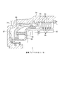
- FIG. 3 is a partially enlarged view of the cross section of the forward clutch FWD / C.
- FIG. 4 is a partially enlarged view of the cross section of the reverse brake REV / B.
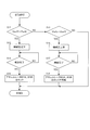
- FIG. 5 is a flowchart showing a control flow according to the embodiment of the present invention.
- FIG. 6 is a timing chart showing an example of control according to the embodiment of the present invention.
- FIG. 1 is a schematic configuration diagram of the vehicle 100.
- the vehicle 100 includes an engine 1, an automatic transmission 3 as a power transmission device, an oil pump 5, and drive wheels 6.
- Engine 1 is an internal combustion engine that uses gasoline, light oil, or the like as fuel, and functions as a driving source for traveling.
- the engine 1 is controlled in rotational speed, torque, and the like based on a command from the controller 10.
- the automatic transmission 3 includes a torque converter 20, a fastening element 60, a belt-type continuously variable transmission mechanism (hereinafter also referred to as “CVT”) 30, and a hydraulic control valve unit 40 (hereinafter simply referred to as “valve unit 40”). And an oil pan 32 for storing oil (operating oil), and a controller 10 as a control device.
- CVT continuously variable transmission mechanism
- valve unit 40 hydraulic control valve unit 40
- the automatic transmission 3 has a range such as a D range, that is, a drive range, an R range, that is, a reverse range, an N range, that is, a neutral range, and a P range, that is, a parking range.
- the range of the automatic transmission 3 is selected by the shift lever 31.
- the D range and the R range are travel ranges
- the N range and the P range are non-travel ranges.
- the torque converter 20 is provided on a power transmission path between the engine 1 and the drive wheels 6.
- the torque converter 20 transmits power through a fluid. Further, the torque converter 20 can enhance the power transmission efficiency of the driving force from the engine 1 by fastening the lock-up clutch 20a.
- the CVT 30 is disposed on the power transmission path between the fastening element 60 and the drive wheel 6, and changes the gear ratio steplessly according to the vehicle speed, the accelerator opening, and the like.
- the CVT 30 includes a primary pulley 30a, a secondary pulley 30b, and a belt 30c wound around the pulleys 30a and 30b.
- the gear ratio is changed steplessly by moving the movable pulley of the primary pulley 30a and the movable pulley of the secondary pulley 30b in the axial direction by the pulley pressure and changing the pulley contact radius of the belt 30c.
- the pulley pressure acting on the primary pulley 30a and the pulley pressure acting on the secondary pulley 30b are regulated by the valve unit 40 using the discharge pressure from the oil pump 5 as a source pressure.
- the differential 12 is connected to the output shaft of the secondary pulley 30b of the CVT 30 via a final reduction gear mechanism (not shown).
- the drive wheel 6 is connected to the differential 12 via a drive shaft 13.
- the fastening element 60 is disposed on a power transmission path between the torque converter 20 and the CVT 30.
- the fastening element 60 has a forward clutch FWD / C as a first fastening element and a reverse brake REV / B as a second fastening element. Engagement or disengagement of the forward clutch FWD / C and the reverse brake REV / B is controlled by the engagement pressure adjusted by the valve unit 40 using the discharge pressure of the oil pump 5 as a source pressure based on a command from the controller 10.
- the oil pump 5 is driven when the rotation of the engine 1 is transmitted through a belt.
- the oil pump 5 is constituted by a vane pump, for example.
- the oil pump 5 sucks up the hydraulic oil stored in the oil pan 32 and supplies the hydraulic oil to the valve unit 40.
- the hydraulic oil supplied to the valve unit 40 is regulated in the valve unit 40 and used for driving the pulleys 30a and 30b, driving the fastening element 60, lubricating each element of the automatic transmission 3, and the like.
- the controller 10 includes a microcomputer having a central processing unit (CPU), a read only memory (ROM), a random access memory (RAM), and an input / output interface (I / O interface).
- the controller 10 can be composed of a plurality of microcomputers. Specifically, the controller 10 can be configured by an ATCU that controls the automatic transmission 3, an SCU that controls the shift range, an ECU that controls the engine 1, and the like. Note that the control unit that controls the accumulators 80A and 80B, which will be described later, is a function in which the controller 10 executes the control as a virtual unit.
- An accelerator opening sensor 53 for detecting the degree an inhibitor switch 54 for detecting a select range of the CVT 30 (a state of a select lever or a select switch for switching forward, reverse, neutral and parking), and a third speed for detecting the rotational speed of the secondary pulley 30b.
- Signals from a rotational speed sensor 55, a pedaling force sensor 56 that detects the pedaling force of the brake, a vehicle speed sensor 57 that detects the vehicle speed V, and an oil temperature sensor 58 that detects the oil temperature are input.
- the controller 10 controls various operations of the engine 1 and the automatic transmission 3 based on these input signals.
- the valve unit 40 includes a hydraulic control circuit C that controls the operation of the forward clutch FWD / C and the reverse brake REV / B (see FIG. 2).
- the hydraulic control circuit C will be described below with reference to FIG.
- the hydraulic control circuit C includes a hydraulic circuit 71, a selection hydraulic actuator 72, a range selection valve 73, an ON / OFF valve 74, a flow path 75, an accumulator 80A, and an accumulator 80B.
- the hydraulic circuit 71 adjusts the pressure of the hydraulic oil discharged from the oil pump 5 in accordance with a command from the controller 10.
- the selection hydraulic actuator 72 is provided downstream of the hydraulic circuit 71.
- the selection hydraulic actuator 72 blocks the flow path 75 in response to a command from the controller 10.
- the selection hydraulic actuator 72 is constituted by, for example, a three-way solenoid valve.
- the range select valve 73 is provided downstream of the select hydraulic actuator 72.
- the hydraulic fluid discharged from the oil pump 5 is supplied to the range select valve 73 through the hydraulic circuit 71 and the select hydraulic actuator 72.
- the range select valve 73 includes a spool (not shown) and an actuator (not shown) that drives the spool. Based on an instruction from the controller 10, the spool is switched to any one of a forward position, a neutral position, and a reverse position. In the forward position, the flow path 75 and the forward clutch FWD / C communicate with each other, and the reverse brake REV / B and the tank T communicate with each other. In the neutral position, the forward clutch FWD / C and the reverse brake REV / B communicate with the tank T. In the reverse position, the flow path 75 and the reverse brake REV / B communicate with each other, and the forward clutch FWD / C and the tank T communicate with each other.
- the accumulator 80A is connected to a flow path 77 that connects the range select valve 73 and the forward clutch FWD / C.
- the accumulator 80B is connected to a flow path 78 that connects the range select valve 73 and the reverse brake REV / B. The specific configuration of the accumulators 80A and 80B will be described later.
- the ON / OFF valve 74 is provided in the branch flow path 76 that branches from between the hydraulic circuit 71 and the selection hydraulic actuator 72 in the flow path 75.
- the ON / OFF valve 74 is configured as a three-way solenoid valve, for example.
- the ON / OFF valve 74 controls the operation of the accumulators 80A and 80B. Specific control of the ON / OFF valve 74 will be described later.
- the range select valve 73 When the driver operates the shift lever 31 to the R range, the range select valve 73 is switched to the reverse position, and the hydraulic oil supplied from the oil pump 5 passes through the hydraulic circuit 71 and the select hydraulic actuator 72 to the reverse brake REV / B. Supplied. As a result, the reverse brake REV / B is engaged and the vehicle 100 moves backward.
- the range select valve 73 When the driver operates the shift lever 31 to the N range or the P range, the range select valve 73 is switched to the neutral position, and the hydraulic oil in the forward clutch FWD / C and the reverse brake REV / B is discharged to the tank T. As a result, the forward clutch FWD / C and the reverse brake REV / B are released, and the automatic transmission 3 enters the neutral state.
- the accumulator 80B has the same configuration as that of the accumulator 80A, and the description thereof is omitted with the same reference numerals. .
- the accumulator 80A includes a cylinder part 81, a piston 82, a first oil chamber 83, a second oil chamber 84, a space 85, and a spring 86 as an elastic member.
- the cylinder part 81 is formed by a substantially cylindrical hole.
- the cylinder part 81 has a large diameter part 81a and a small diameter part 81b having a smaller diameter than the large diameter part 81a.
- the piston 82 is slidably accommodated in the cylinder part 81.
- the piston 82 has a large diameter portion 82a that slides on the large diameter portion 81a and a small diameter portion 82b that slides on the small diameter portion 81b.
- the first oil chamber 83 is defined by a small diameter part 81 b of the cylinder part 81 and a small diameter part 82 b of the piston 82 in the small diameter part 81 b of the cylinder part 81.
- the first oil chamber 83 of the accumulator 80A is connected to the flow path 77, and the first oil chamber 83 of the accumulator 80B is connected to the flow path 78.
- the second oil chamber 84 is defined by the large diameter portion 81a of the cylinder portion 81, the large diameter portion 82a of the piston 82, and the small diameter portion 82b on the small diameter portion 81b side of the large diameter portion 81a of the cylinder portion 81.
- the second oil chamber 84 is connected to the ON / OFF valve 74 through the branch flow path 76.
- the space 85 is provided on the opposite side of the large diameter portion 81a of the cylinder portion 81 with the second oil chamber 84 and the large diameter portion 82a interposed therebetween.
- the spring 86 is provided in the space 85.
- the spring 86 urges the piston 82 in the direction in which the volumes of the first oil chamber 83 and the second oil chamber 84 are reduced.
- a gas such as nitrogen may be filled in the space 85 as an elastic member.
- the accumulators 80A and 80B configured as described above absorb the shock caused by the hydraulic pressure during the operation of the forward clutch FWD / C and the reverse brake REV / B and the pulsation of the hydraulic pressure in the flow paths 77 and 78.
- the forward clutch FWD / C includes a clutch drum 61, a clutch hub 62, a driven plate 63, a drive plate 64, a dish plate 65 as a first dish plate, and a piston 66 as a first piston.
- the clutch drum 61 and the clutch hub 62 are arranged coaxially.
- the clutch drum 61 is connected to a rotating element (shaft, gear, etc.) not shown.
- the clutch hub 62 is connected to another rotating element (shaft, gear, etc.) not shown.
- the driven plate 63 is attached to the clutch drum 61 so as to be slidable in the axial direction by spline coupling.
- a drive plate 64 is attached to the clutch hub 62 so as to be slidable in the axial direction by spline coupling.
- the driven plate 63 and the drive plate 64 are alternately arranged. Clutch facings are provided on the friction surfaces on both sides of the drive plate 64.
- the clutch drum 61 transmits the rotation input from the rotating element connected to the clutch drum 61 to the clutch hub 62 via the driven plate 63 and the drive plate 64.
- the piston 66 is disposed so as to be displaceable with respect to the axial direction of the forward clutch FWD / C.
- the dish plate 65 is constituted by a member having a spring property such as a disc spring, for example.
- the forward clutch FWD / C further includes a piston chamber 67, a canceller chamber 68, and a partition plate 69.
- the piston chamber 67 as the first hydraulic chamber is defined between the clutch drum 61 and the piston 66.
- the piston chamber 67 is connected to a range select valve 73 (see FIG. 2) through a flow path 77.
- a return spring 70 is provided between the piston 66 and the partition plate 69.
- the return spring 70 biases the piston 66 toward the release side (the direction in which the pressure contact between the driven plate 63 and the drive plate 64 is released).
- the canceller chamber 68 is defined between the partition plate 69 and the piston 66. Oil is filled to prevent the hydraulic pressure in the piston chamber 67 from fluctuating due to centrifugal force.
- the reverse brake REV / B includes a case 91, a hub 92 as a rotating body, a first plate 93, a second plate 94, a dish plate 95 as a second dish plate, and a piston 96 as a second piston. .
- the first plate 93 is attached to the case 91 so as to be slidable in the axial direction by spline coupling.
- a second plate 94 is attached to the hub 92 so as to be slidable in the axial direction by spline coupling.
- the first plate 93 and the second plate 94 are alternately arranged. Clutch facings are provided on the friction surfaces on both sides of the second plate 94.
- the hub 92 is restricted from rotating relative to the case 91 when the first plate 93 and the second plate 94 are pressed against (fastened).
- the piston 96 is disposed so as to be displaceable with respect to the axial direction of the reverse brake REV / B.
- the dish plate 95 is configured by a member having a spring property such as a disc spring, for example.
- the reverse brake REV / B further includes a piston chamber 97 and a partition plate 99.
- a piston chamber 97 as a second hydraulic chamber is defined between the case 91 and the piston 96.
- the piston chamber 97 is connected to the range select valve 73 (see FIG. 2) through the flow path 78.
- the piston 96 moves in a direction in which the first plate 93 and the second plate 94 are pressed against each other.
- a return spring 98 is provided between the piston 96 and the partition plate 99.
- the return spring 98 urges the piston 96 toward the release side (the direction in which the pressure contact between the first plate 93 and the second plate 94 is released).
- the reverse brake REV / B also has a dish plate 95. For this reason, even in the reverse brake REV / B, it is not easy to achieve both reduction of the hydraulic pressure loss shock and improvement of responsiveness when the reverse brake REV / B is operated only by adjusting the spring constant of the dish plate 95. .
- accumulators 80A and 80B are provided in flow paths 77 and 78 for supplying hydraulic pressure to forward clutch FWD / C and reverse brake REV / B, respectively, and the operation of accumulators 80A and 80B is controlled by controller 10.
- controller 10 controls the operation of accumulators 80A and 80B to achieve both reduction of hydraulic pressure loss shock and improvement of responsiveness when the engaging element 60 (forward clutch FWD / C and reverse brake REV / B) is operated.
- the control of the accumulators 80A and 80B will be specifically described with reference to FIG.
- FIG. 5 is a flowchart showing a control flow of the accumulators 80A and 80B according to the present embodiment.
- the controller 10 determines whether or not the shift range has been switched from the D range or R range to the P range or N range. That is, the controller 10 determines whether or not the shift range is switched from the travel range to the non-travel range. Based on the signal from the inhibitor switch 54, the controller 10 determines whether or not the shift lever 31 has been switched from the D range or R range to the P range or R range. If the shift range has been switched from the D range or R range to the P range or R range, the process proceeds to step S12. If the shift range has not been switched from the D range or R range to the P range or R range, the process proceeds to step S15.
- step S12 the fastening pressure is reduced. Specifically, the controller 10 switches the range select valve 73 to the neutral position. As a result, the hydraulic pressure (fastening pressure) of the fastened fastening element 60 (forward clutch FWD / C or reverse brake REV / B) decreases.
- step S13 it is determined whether or not release of the engaged element 60 (forward clutch FWD / C or reverse brake REV / B) that has been engaged is completed. That is, the controller 10 determines whether or not the shift range has been switched. Specifically, the controller 10 determines whether or not a predetermined time has elapsed since the range select valve 73 was switched to the neutral position. If the predetermined time has elapsed, the process proceeds to step S14. If the predetermined time has not elapsed, the determination in step S13 is repeated. Note that, for example, the pressures of the flow channel 77 and the flow channel 78 may be detected, and the release completion of the fastening element 60 may be determined based on the pressure.
- step S14 the accumulators 80A and 80B are locked. Specifically, the ON / OFF valve 74 is turned ON to supply hydraulic pressure to the second oil chamber 84 of the accumulators 80A and 80B.
- the hydraulic pressure supplied to the second oil chamber 84 is also referred to as “back pressure”.
- the piston 82 moves in the direction in which the spring 86 is compressed (left direction in FIG. 2), and comes into contact with the side wall on the space 85 side of the large diameter portion 81a. And stop. That is, when the ON / OFF valve 74 is in the ON state, the piston 82 is locked (held) at this position. For this reason, even if the pressure of the forward clutch FWD / C, specifically, the pressure in the piston chamber 67 decreases, the pressure (release pressure) accumulated in the accumulator 80A is supplied to the piston chamber 67 through the flow path 77. None happen.
- step S15 the controller 10 determines whether or not the shift range has been switched from the P range or the N range to the D range or the R range. That is, the controller 10 determines whether or not the shift range is switched from the non-traveling range to the traveling range. Based on the signal from the inhibitor switch 54, the controller 10 determines whether or not the shift lever 31 has been switched from the P range or the N range to the D range or the R range. If the shift range has been switched from the P range or N range to the D range or R range, the process proceeds to step S16, and the shift range has not been switched, or the travel range to the travel range (for example, the D range to the R range). ), Or if it is determined that the non-running range is switched to the non-running range (for example, P range to N range), the process proceeds to END.
- step S16 the fastening pressure is increased. Specifically, the controller 10 switches the range select valve 73 to the forward position or the reverse position according to the selected shift range. As a result, the hydraulic pressure (engagement pressure) of the engagement element 60 (forward clutch FWD / C or reverse brake REV / B) increases.
- step S17 it is determined whether or not the engagement of the engagement element 60 (forward clutch FWD / C or reverse brake REV / B) has been completed. That is, the controller 10 determines whether or not the shift range has been switched. Specifically, the controller 10 determines whether or not a predetermined time has elapsed since the range select valve 73 was switched to the forward position or the reverse position. If the predetermined time has elapsed, the process proceeds to step S18. If the predetermined time has not elapsed, the determination in step S17 is repeated. Note that, for example, the pressures of the flow path 77 and the flow path 78 may be detected, and the fastening completion of the fastening element 60 may be determined based on the pressure.
- step S18 the accumulators 80A and 80B are unlocked. Specifically, the ON / OFF valve 74 is turned OFF to reduce the hydraulic pressure (back pressure) in the second oil chamber 84 of the accumulators 80A and 80B.
- the piston 82 moves in the direction in which the second oil chamber 84 contracts (rightward in FIG. 2) due to the urging force of the spring 86.
- the piston 82 stops at a position where the urging force of the spring 86 and the urging force by the hydraulic pressure acting on the small diameter portion 82b of the piston 82 are balanced. That is, when the ON / OFF valve 74 is OFF, the piston 82 is unlocked. For this reason, when the pressure of the forward clutch FWD / C, specifically, the pressure in the piston chamber 67 decreases, the pressure (release pressure) is supplied from the accumulator 80A to the piston chamber 67 through the flow path 77.
- the discharge pressure of the accumulator 80A can be supplied to the piston chamber 67.
- the pressure accumulation function of the accumulator 80A is effective.
- the accumulator 80B can supply the discharge pressure of the accumulator 80B to the piston chamber 97 when the ON / OFF valve 74 is OFF. That is, when the ON / OFF valve 74 is OFF, the pressure accumulation function of the accumulator 80B is effective.
- FIG. 6 shows an example in which the shift range is switched in the order of D ⁇ N ⁇ D.
- the controller 10 switches the range select valve 73 to the neutral position.
- the hydraulic pressure (fastening pressure) in the piston chamber 67 of the forward clutch FWD / C is discharged to the tank T through the range select valve 73.
- the ON / OFF valve 74 is in the OFF state, the locked state of the accumulator 80A is released.
- the hydraulic pressure in the piston chamber 67 of the FWD / C decreases, the pressure (discharge pressure) accumulated in the accumulator 80 ⁇ / b> A is supplied to the flow channel 77.
- a rapid drop in the hydraulic pressure in the piston chamber 67 of the forward clutch FWD / C is suppressed, so that a hydraulic pressure release shock when the forward clutch FWD / C is released can be reduced.
- the controller 10 switches the ON / OFF valve 74 to ON at time t3 after a predetermined time has elapsed from time t1, specifically, after the release of the forward clutch FWD / C is completed (time t2).
- time t2 the hydraulic oil discharged from the oil pump 5 is supplied to the second oil chamber 84 through the flow path 75, the branch flow path 76 and the ON / OFF valve 74.
- the accumulator 80A is locked (time t4). That is, while the forward clutch FWD / C is maintained in the released state, the supply of the discharge pressure of the accumulator 80A to the piston chamber 67 is stopped.
- the controller 10 switches the range select valve 73 to the forward position.
- the hydraulic oil discharged from the oil pump 5 is supplied from the range select valve 73 to the piston chamber 67 of the forward clutch FWD / C through the flow path 77.
- the piston 82 does not move.
- substantially the entire amount of hydraulic oil discharged from the oil pump 5 is supplied to the piston chamber 67 of the forward clutch FWD / C.
- the engaging speed of the forward clutch FWD / C becomes faster than when the accumulator 80A is not locked. That is, by stopping the supply of the discharge pressure of the accumulator 80A to the piston chamber 67 from the start of engagement of the forward clutch FWD / C to the completion of engagement, the responsiveness when the forward clutch FWD / C is engaged is improved.
- the controller 10 switches the ON / OFF valve 74 to OFF. Thereby, the hydraulic pressure (back pressure) in the second oil chamber 84 is discharged to the tank T through the ON / OFF valve 74.
- the first oil chamber 83 is supplied with high-pressure hydraulic oil (a hydraulic pressure that can engage the forward clutch FWD / C).
- the piston 82 is held at a position in contact with the side wall.
- Switching of the ON / OFF valve 74 to OFF may be performed at any time as long as it is after the time when the fastening pressure has increased to a pressure at which the piston 82 can be maintained in contact with the side wall on the space 85 side. .
- the accumulator 80A, Lock 80B when switching from the non-traveling range (P range, N range) to the traveling range (D range, R range), the lock of the accumulators 80A, 80B is released after the fastening of the fastening element 60 is completed.
- the fastening element 60 By locking the accumulators 80A and 80B, that is, by stopping the discharging function of the accumulators 80A and 80B, the fastening element 60 (forward clutch FWD / C or reverse brake depending only on the characteristics of the dish plates 65 and 95 at a predetermined timing). REV / B) can be engaged or released. Further, by releasing the lock of the accumulators 80A and 80B, that is, by enabling the discharging function of the accumulators 80A and 80B, the characteristics of the dish plates 65 and 95 and the characteristics of the accumulators 80A and 80B are complemented at other predetermined timings.
- the engaging element 60 (the forward clutch FWD / C or the reverse brake REV / B) used for the purpose can be engaged or released.
- the spring characteristics (spring constant) of the dish plates 65 and 95 are set to one of the fastening time and the releasing time, and the discharging function of the accumulators 80A and 80B is stopped (invalid) when one of the fastening time and the releasing time. To keep).
- the spring characteristic (spring constant) of the dish plates 65 and 95 is set to one of fastening and releasing.
- the lack of spring characteristics on the other side can be supplemented by the characteristics of the accumulators 80A and 80B.
- the power transmission device (automatic transmission 3) includes pistons 66 and 96, a hydraulic chamber (piston chambers 67 and 97) to which hydraulic pressure for moving the pistons 66 and 96 in a predetermined direction, and pistons 66 and 96 in a predetermined direction.
- a hydraulic chamber to which hydraulic pressure for moving the pistons 66 and 96 in a predetermined direction
- pistons 66 and 96 in a predetermined direction are connected to the hydraulic chambers (piston chambers 67, 97) and the fastening elements 60 (forward clutch FWD / C, reverse brake REV / B) having dish plates 65, 95 that generate urging forces that move in the opposite direction.
- accumulators 80A and 80B, and a controller (controller 10) for stopping the supply of the release pressures of the accumulators 80A and 80B to the hydraulic chambers (piston chambers 67 and 97).
- the fastening or releasing operation depending only on the characteristics of the dish plates 65 and 95 can be performed at a predetermined timing.
- a fastening or releasing operation that complementarily uses the characteristics of the dish plates 65 and 95 and the characteristics of the accumulators 80A and 80B. Therefore, it is possible to satisfy both the hydraulic response request at the time of fastening and the hydraulic response request at the time of release.
- control unit shifts the engaging element 60 (forward clutch FWD / C, reverse brake REV / B) from the disengaged state to the engaged state, the hydraulic chamber (piston chamber 67, 97).
- the disabling (stopping) the discharging function of the accumulators 80A and 80B it is possible to improve the engagement response of the engagement element 60 (forward clutch FWD / C, reverse brake REV / B). Further, at this time, the function of preventing the sudden engagement of the fastening elements 60 (forward clutch FWD / C, reverse brake REV / B) by the accumulators 80A and 80B is lowered, but since the dish plates 65 and 95 are present, the fastening elements 60 ( The forward clutch FWD / C and the reverse brake REV / B) can be sufficiently provided with a function of preventing sudden engagement.
- the controller (controller 10) is configured to release hydraulic pressure chambers (piston chambers 67, 80B) of the accumulators 80A and 80B from the start of engagement of the engagement element 60 (forward clutch FWD / C, reverse brake REV / B) to the completion of engagement. 97).
- control unit controls the hydraulic chambers (piston chambers 67, 80B) of the discharge pressures of the accumulators 80A, 80B. 97).
- a method of locking the accumulators 80A and 80B after an instruction to make a transition from the released state to the engaged state is conceivable, but there is a time lag between the instruction and the locking. For this reason, the time lag at the time of the state transition of the fastening element 60 (forward clutch FWD / C, reverse brake REV / B) can be shortened by setting the accumulators 80A and 80B in the locked state in advance.
- control unit causes the engaging element 60 (forward clutch FWD / C, reverse brake REV / B) to transition from the engaged state to the released state, the hydraulic chamber (piston chamber 67, 97) Release the supply stop.
- the force against the dish plates 65 and 95 is enabled by enabling the discharging function of the accumulators 80A and 80B.
- the engagement capacity of the engagement element 60 (forward clutch FWD / C, reverse brake REV / B) can be moderated.
- the hydraulic pressure release of the engaging element 60 (forward clutch FWD / C, reverse brake REV / B) can be moderated, and the hydraulic pressure release shock can be suppressed.
- the controller controls the hydraulic chambers (piston chamber 67, 97) Release the supply stop.
- the lock release state of the accumulators 80A and 80B is maintained from the start of release of the engaging element 60 (forward clutch FWD / C, reverse brake REV / B) to the completion of release.
- control unit controls the hydraulic chambers (piston chambers 67, 80B) of the discharge pressures of the accumulators 80A, 80B. 97) Release the supply stop.
- a method of controlling the back pressure of the accumulators 80A and 80B after an instruction to shift the engaging element 60 (forward clutch FWD / C, reverse brake REV / B) from the engaged state to the released state is also conceivable.
- the engaging element 60 forward clutch FWD / C, reverse brake REV / B
- the lag of the state transition of the fastening element 60 can be shortened by making the back pressure state a preparation state in advance.
- the accumulators 80A and 80B are locked at a position where the pressure accumulation function is stopped (a position where pressure is not accumulated, that is, a position where the spring 86 is the maximum length) and a position where the pressure accumulation function is functioned (a position where pressure is accumulated, ie, a spring).
- the position where 86 is the minimum length) is conceivable.
- the accumulator function is restored when the lock of the accumulators 80A and 80B is released after the fastening (when the back pressure is released), and the hydraulic pressure in the piston chambers 67 and 97 is maintained despite the complete fastening. It can change. For this reason, the latter configuration can prevent such a change in hydraulic pressure.
- the control unit (controller 10) stops supply by supplying back pressure to the accumulators 80A and 80B.
- the system can be reduced in size compared to the case where the pistons 82 of the accumulators 80A and 80B are moved to the lock position using, for example, an electromagnetic actuator.
- the power transmission device (automatic transmission 3) includes a first piston (piston 66), a first hydraulic chamber (piston chamber 67) for supplying hydraulic pressure for moving the first piston (piston 66) in a first predetermined direction, A first fastening element (forward clutch FWD / C) having a first dish plate (dish plate 65) that generates a biasing force that moves the first piston (piston 66) in a direction opposite to the first predetermined direction; The second piston (piston 96), the second hydraulic chamber (piston chamber 97) for supplying hydraulic pressure for moving the second piston (piston 96) in the second predetermined direction, and the second piston (piston 96) for the second predetermined A second engagement plate (reverse brake REV / B) having a second dish plate (dish plate 95) for generating an urging force to move in a direction opposite to the direction A first accumulator (accumulator 80A) connected to the first hydraulic chamber (piston chamber 67), a second accumul
- the first accumulator (accumulator 80A) and the second accumulator (accumulator 80B) are simultaneously shifted to the locked state by controlling the control unit (controller 10) for stopping supply to the chamber 97) and the control unit (controller 10). Lock Having a granulation (branch channel 76 and ON / OFF valve 74), the.
- This configuration has a lock structure (branch flow path 76 and ON / OFF valve 74) that simultaneously shifts the plurality of accumulators 80A and 80B to the locked state. This makes it possible to simplify the system and reduce costs.
- a branch flow path 76 that is a common back pressure supply oil path and an ON / OFF valve 74 that controls the branch flow path 76 are provided.
- the pistons 82 of the accumulators 80A and 80B can be locked simultaneously with a common member.
- the common member corresponds to the lock structure.
- control unit stops supplying the discharge pressures of the accumulators 80A and 80B to the hydraulic chambers (piston chambers 67 and 97).
- the hydraulic chamber of the discharge pressures of the accumulators 80A and 80B after an instruction to shift the engagement element 60 (forward clutch FWD / C, reverse brake REV / B) from the released state (non-traveling range) to the engaged state (traveling range) is given. It is also conceivable to stop the supply to (piston chambers 67, 97). However, there is a time lag between the instruction and the supply of hydraulic pressure. For this reason, when the non-traveling range is selected, the time lag at the time of the state transition of the engaging element 60 (forward clutch FWD / C, reverse brake REV / B) is set by locking accumulators 80A and 80B in advance. Can be shortened.
- the fastening element 60 forward clutch FWD / C, reverse brake REV / B
- the fastening element 60 forward clutch FWD / C, reverse brake REV / B
- the first engagement element (forward clutch FWD / C) is a forward engagement element
- the second engagement element (reverse brake REV / B) is a reverse engagement element.
- valves for controlling the accumulators 80A and 80B may be provided.
- the locking means of the accumulators 80A and 80B is not limited to the configuration for supplying the back pressure, and for example, an electromagnetic actuator may be used.
- accumulators are provided for both the forward clutch FWD / C and the reverse brake REV / B.
- the hydraulic response request at the time of engagement and the hydraulic response request at the time of release If both are not so required, an accumulator may be provided only in the forward clutch FWD / C.
- the automatic transmission 3 has been described as an example of the power transmission device, but the power transmission device is not limited to this, and may be, for example, a speed reducer or a forward / reverse switching mechanism.
Landscapes
- Engineering & Computer Science (AREA)
- General Engineering & Computer Science (AREA)
- Mechanical Engineering (AREA)
- Physics & Mathematics (AREA)
- Fluid Mechanics (AREA)
- Hydraulic Clutches, Magnetic Clutches, Fluid Clutches, And Fluid Joints (AREA)
- Control Of Transmission Device (AREA)
Abstract
La présente invention concerne une transmission automatique comprenant : un élément de couplage ayant un piston, une chambre de piston à laquelle une pression hydraulique pour déplacer le piston dans une direction prédéterminée est fournie ; et une tôle emboutie qui génère une force de poussée pour déplacer le piston dans la direction opposée à la direction prédéterminée ; un accumulateur qui se raccorde à la chambre de piston ; et une unité de commande qui arrête l'alimentation en pression de la chambre de piston, la pression ayant été libérée de l'accumulateur.
Priority Applications (1)
| Application Number | Priority Date | Filing Date | Title |
|---|---|---|---|
| JP2020501605A JP6982676B2 (ja) | 2018-02-22 | 2019-01-24 | 動力伝達装置 |
Applications Claiming Priority (2)
| Application Number | Priority Date | Filing Date | Title |
|---|---|---|---|
| JP2018029620 | 2018-02-22 | ||
| JP2018-029620 | 2018-02-22 |
Publications (1)
| Publication Number | Publication Date |
|---|---|
| WO2019163393A1 true WO2019163393A1 (fr) | 2019-08-29 |
Family
ID=67688283
Family Applications (1)
| Application Number | Title | Priority Date | Filing Date |
|---|---|---|---|
| PCT/JP2019/002365 Ceased WO2019163393A1 (fr) | 2018-02-22 | 2019-01-24 | Dispositif de transmission de puissance |
Country Status (2)
| Country | Link |
|---|---|
| JP (1) | JP6982676B2 (fr) |
| WO (1) | WO2019163393A1 (fr) |
Citations (4)
| Publication number | Priority date | Publication date | Assignee | Title |
|---|---|---|---|---|
| JPS5018611B1 (fr) * | 1970-02-18 | 1975-07-01 | ||
| JPS60126734U (ja) * | 1984-02-06 | 1985-08-26 | トヨタ自動車株式会社 | 車輌用自動変速機の油圧制御装置 |
| JPH0281928U (fr) * | 1988-12-14 | 1990-06-25 | ||
| JP2016084847A (ja) * | 2014-10-24 | 2016-05-19 | アイシン精機株式会社 | 流体制御装置 |
-
2019
- 2019-01-24 WO PCT/JP2019/002365 patent/WO2019163393A1/fr not_active Ceased
- 2019-01-24 JP JP2020501605A patent/JP6982676B2/ja active Active
Patent Citations (4)
| Publication number | Priority date | Publication date | Assignee | Title |
|---|---|---|---|---|
| JPS5018611B1 (fr) * | 1970-02-18 | 1975-07-01 | ||
| JPS60126734U (ja) * | 1984-02-06 | 1985-08-26 | トヨタ自動車株式会社 | 車輌用自動変速機の油圧制御装置 |
| JPH0281928U (fr) * | 1988-12-14 | 1990-06-25 | ||
| JP2016084847A (ja) * | 2014-10-24 | 2016-05-19 | アイシン精機株式会社 | 流体制御装置 |
Also Published As
| Publication number | Publication date |
|---|---|
| JP6982676B2 (ja) | 2021-12-17 |
| JPWO2019163393A1 (ja) | 2021-02-04 |
Similar Documents
| Publication | Publication Date | Title |
|---|---|---|
| US8801573B2 (en) | Power transmitting apparatuses | |
| US8758198B2 (en) | Power transmitting apparatuses | |
| KR101601603B1 (ko) | 무단 변속기의 변속 제어 장치 | |
| CN104246316B (zh) | 自动变速器的控制方法及控制装置、以及自动变速器系统 | |
| JP5874839B2 (ja) | 変速機のブレーキ装置及びその制御システム | |
| KR101356264B1 (ko) | 코스트 스톱 차량 및 코스트 스톱 방법 | |
| US8690733B2 (en) | Vehicle control system and control method thereof | |
| US10730523B2 (en) | Vehicle drive device and method of controlling vehicle drive device | |
| US20110048552A1 (en) | Control apparatus for automatic transmission | |
| US20140315687A1 (en) | Hydraulic pressure control device and vehicle control device | |
| US8506454B2 (en) | Fluid pressure control device for automatic transmission | |
| US20150217773A1 (en) | Automatic transmission and control method for the automatic transmission | |
| JP6439756B2 (ja) | 車両用変速機の制御装置 | |
| JP4573796B2 (ja) | 自動変速機の油圧制御装置 | |
| JP5660733B2 (ja) | 動力伝達装置 | |
| JP6982676B2 (ja) | 動力伝達装置 | |
| JP2019147445A (ja) | 車両の制御装置及び車両の制御方法 | |
| CN111059280A (zh) | 用于车辆的动力传递系统的控制设备 | |
| JP4573795B2 (ja) | 自動変速機の油圧制御装置 | |
| JP6721309B2 (ja) | 自動変速機 | |
| US10302192B2 (en) | Method and device for controlling automatic transmission | |
| JP6206393B2 (ja) | 自動変速機の油圧制御装置および油圧制御方法 | |
| JP2007057073A (ja) | 無段変速機の制御装置 | |
| JP2019090464A (ja) | 変速機の制御装置 | |
| JP2004332904A (ja) | 無段変速機の変速比制御装置 |
Legal Events
| Date | Code | Title | Description |
|---|---|---|---|
| 121 | Ep: the epo has been informed by wipo that ep was designated in this application |
Ref document number: 19757024 Country of ref document: EP Kind code of ref document: A1 |
|
| ENP | Entry into the national phase |
Ref document number: 2020501605 Country of ref document: JP Kind code of ref document: A |
|
| NENP | Non-entry into the national phase |
Ref country code: DE |
|
| 122 | Ep: pct application non-entry in european phase |
Ref document number: 19757024 Country of ref document: EP Kind code of ref document: A1 |