WO2019164249A1 - 무선 통신 시스템에 있어서 통신 장치의 동작 방법 및 이를 이용한 통신 장치 - Google Patents
무선 통신 시스템에 있어서 통신 장치의 동작 방법 및 이를 이용한 통신 장치 Download PDFInfo
- Publication number
- WO2019164249A1 WO2019164249A1 PCT/KR2019/002049 KR2019002049W WO2019164249A1 WO 2019164249 A1 WO2019164249 A1 WO 2019164249A1 KR 2019002049 W KR2019002049 W KR 2019002049W WO 2019164249 A1 WO2019164249 A1 WO 2019164249A1
- Authority
- WO
- WIPO (PCT)
- Prior art keywords
- information
- determined
- level
- size
- pdcch
- Prior art date
- Legal status (The legal status is an assumption and is not a legal conclusion. Google has not performed a legal analysis and makes no representation as to the accuracy of the status listed.)
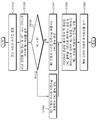
- Ceased
Links
Images




Classifications
-
- H—ELECTRICITY
- H03—ELECTRONIC CIRCUITRY
- H03M—CODING; DECODING; CODE CONVERSION IN GENERAL
- H03M13/00—Coding, decoding or code conversion, for error detection or error correction; Coding theory basic assumptions; Coding bounds; Error probability evaluation methods; Channel models; Simulation or testing of codes
- H03M13/03—Error detection or forward error correction by redundancy in data representation, i.e. code words containing more digits than the source words
- H03M13/05—Error detection or forward error correction by redundancy in data representation, i.e. code words containing more digits than the source words using block codes, i.e. a predetermined number of check bits joined to a predetermined number of information bits
- H03M13/13—Linear codes
-
- H—ELECTRICITY
- H03—ELECTRONIC CIRCUITRY
- H03M—CODING; DECODING; CODE CONVERSION IN GENERAL
- H03M13/00—Coding, decoding or code conversion, for error detection or error correction; Coding theory basic assumptions; Coding bounds; Error probability evaluation methods; Channel models; Simulation or testing of codes
- H03M13/29—Coding, decoding or code conversion, for error detection or error correction; Coding theory basic assumptions; Coding bounds; Error probability evaluation methods; Channel models; Simulation or testing of codes combining two or more codes or code structures, e.g. product codes, generalised product codes, concatenated codes, inner and outer codes
- H03M13/2906—Coding, decoding or code conversion, for error detection or error correction; Coding theory basic assumptions; Coding bounds; Error probability evaluation methods; Channel models; Simulation or testing of codes combining two or more codes or code structures, e.g. product codes, generalised product codes, concatenated codes, inner and outer codes using block codes
-
- H—ELECTRICITY
- H04—ELECTRIC COMMUNICATION TECHNIQUE
- H04L—TRANSMISSION OF DIGITAL INFORMATION, e.g. TELEGRAPHIC COMMUNICATION
- H04L1/00—Arrangements for detecting or preventing errors in the information received
-
- H—ELECTRICITY
- H04—ELECTRIC COMMUNICATION TECHNIQUE
- H04L—TRANSMISSION OF DIGITAL INFORMATION, e.g. TELEGRAPHIC COMMUNICATION
- H04L1/00—Arrangements for detecting or preventing errors in the information received
- H04L1/0001—Systems modifying transmission characteristics according to link quality, e.g. power backoff
- H04L1/0009—Systems modifying transmission characteristics according to link quality, e.g. power backoff by adapting the channel coding
- H04L1/0011—Systems modifying transmission characteristics according to link quality, e.g. power backoff by adapting the channel coding applied to payload information
-
- H—ELECTRICITY
- H04—ELECTRIC COMMUNICATION TECHNIQUE
- H04L—TRANSMISSION OF DIGITAL INFORMATION, e.g. TELEGRAPHIC COMMUNICATION
- H04L1/00—Arrangements for detecting or preventing errors in the information received
- H04L1/0001—Systems modifying transmission characteristics according to link quality, e.g. power backoff
- H04L1/0036—Systems modifying transmission characteristics according to link quality, e.g. power backoff arrangements specific to the receiver
- H04L1/0038—Blind format detection
-
- H—ELECTRICITY
- H04—ELECTRIC COMMUNICATION TECHNIQUE
- H04L—TRANSMISSION OF DIGITAL INFORMATION, e.g. TELEGRAPHIC COMMUNICATION
- H04L1/00—Arrangements for detecting or preventing errors in the information received
- H04L1/004—Arrangements for detecting or preventing errors in the information received by using forward error control
- H04L1/0056—Systems characterized by the type of code used
- H04L1/0057—Block codes
-
- H—ELECTRICITY
- H04—ELECTRIC COMMUNICATION TECHNIQUE
- H04L—TRANSMISSION OF DIGITAL INFORMATION, e.g. TELEGRAPHIC COMMUNICATION
- H04L1/00—Arrangements for detecting or preventing errors in the information received
- H04L1/004—Arrangements for detecting or preventing errors in the information received by using forward error control
- H04L1/0056—Systems characterized by the type of code used
- H04L1/0061—Error detection codes
-
- H—ELECTRICITY
- H04—ELECTRIC COMMUNICATION TECHNIQUE
- H04L—TRANSMISSION OF DIGITAL INFORMATION, e.g. TELEGRAPHIC COMMUNICATION
- H04L1/00—Arrangements for detecting or preventing errors in the information received
- H04L1/004—Arrangements for detecting or preventing errors in the information received by using forward error control
- H04L1/0072—Error control for data other than payload data, e.g. control data
-
- H—ELECTRICITY
- H04—ELECTRIC COMMUNICATION TECHNIQUE
- H04L—TRANSMISSION OF DIGITAL INFORMATION, e.g. TELEGRAPHIC COMMUNICATION
- H04L5/00—Arrangements affording multiple use of the transmission path
-
- H—ELECTRICITY
- H04—ELECTRIC COMMUNICATION TECHNIQUE
- H04W—WIRELESS COMMUNICATION NETWORKS
- H04W72/00—Local resource management
- H04W72/20—Control channels or signalling for resource management
- H04W72/23—Control channels or signalling for resource management in the downlink direction of a wireless link, i.e. towards a terminal
-
- H—ELECTRICITY
- H03—ELECTRONIC CIRCUITRY
- H03M—CODING; DECODING; CODE CONVERSION IN GENERAL
- H03M13/00—Coding, decoding or code conversion, for error detection or error correction; Coding theory basic assumptions; Coding bounds; Error probability evaluation methods; Channel models; Simulation or testing of codes
- H03M13/03—Error detection or forward error correction by redundancy in data representation, i.e. code words containing more digits than the source words
- H03M13/05—Error detection or forward error correction by redundancy in data representation, i.e. code words containing more digits than the source words using block codes, i.e. a predetermined number of check bits joined to a predetermined number of information bits
- H03M13/09—Error detection only, e.g. using cyclic redundancy check [CRC] codes or single parity bit
Definitions
- the present disclosure relates to wireless communication, and more particularly, to a method of operating a communication device and a communication device using the same in a wireless communication system.
- Massive Machine Type Communications which connects multiple devices and objects to provide various services anytime and anywhere, is also one of the major issues to be considered in next-generation communication.
- Next-generation wireless access technology considering improved mobile broadband communication, Massive MTC, Ultra-Reliable and Low Latency Communication (URLLC), etc. May be referred to as new radio access technology (RAT) or new radio (NR).
- RAT new radio access technology
- NR new radio
- LTE long term evolution
- data to be transmitted is divided into multiple code blocks, and channel coding and cyclic redundancy check (CRC) are added to each code block and included in the transport block. After that, it transmits through one data channel.
- CRC channel coding and cyclic redundancy check
- An object of the present specification is to provide a method for operating a communication device and a communication device using the same in a wireless communication system having improved performance.
- a method of operating a communication device determines first information associated with an aggregation level for a PDCCH and second information associated with a mother code size for a polar code, wherein the aggregation level is a first level.
- the mothercode size being associated with the first to third sizes, and the second information determined according to the first information; Determining whether the first information is determined at a third level; And when it is determined that the first information is determined at the third level, generating a CRC block comprising a first type of masking sequence.
- a mother code size of a correct size may be selected.
- the number of masking sequences associated with the aggregation level for the PDCCH can be reduced, overhead of the wireless communication system can be reduced.
- a wireless communication system with improved performance can be provided.
- FIG 1 illustrates an existing wireless communication system.
- FIG. 2 is a block diagram illustrating a radio protocol structure for a user plane.
- FIG. 3 is a block diagram illustrating a radio protocol architecture for a control plane.
- FIG. 4 illustrates a system structure of a next generation wireless access network to which NR is applied.
- FIG. 5 illustrates a frame structure that can be applied in the NR.
- FIG. 7 is a diagram showing the difference between the conventional control area and the CORESET in the NR.
- FIG. 8 shows an example of a frame structure that can be used in NR.
- FIG. 9 is a diagram illustrating the concept of polar coding.
- FIG. 10 is a diagram illustrating a polarization tendency along the length of a code block.
- FIG. 11 is a diagram illustrating a basic module of a polar code.
- FIG. 12 is a diagram of an example of a channel combination having an N level.
- 13 and 14 show the structure of an input bit according to a CRC block.
- 15 is a flowchart illustrating a method of operating a communication device in a wireless communication system according to an exemplary embodiment.
- 16 is a flowchart illustrating a method of operating a communication device in a wireless communication system according to another embodiment.
- 17 is a block diagram illustrating components of a transmitting apparatus and a receiving apparatus according to the present embodiment.
- FIG. 18 shows an example of a structure of a signal processing module in a transmission device.
- FIG. 19 shows another example of a structure of a signal processing module in a transmission device.
- FIG. 20 illustrates an example of a wireless communication device according to an embodiment of the present invention.
- E-UTRAN Evolved-UMTS Terrestrial Radio Access Network
- LTE Long Term Evolution
- the E-UTRAN includes a base station (BS) 20 that provides a control plane and a user plane to a user equipment (UE).
- the terminal 10 may be fixed or mobile and may be called by other terms such as a mobile station (MS), a user terminal (UT), a subscriber station (SS), a mobile terminal (MT), a wireless device (Wireless Device), and the like.
- the base station 20 refers to a fixed station communicating with the terminal 10, and may be referred to by other terms such as an evolved-NodeB (eNB), a base transceiver system (BTS), an access point, and the like.
- eNB evolved-NodeB
- BTS base transceiver system
- access point and the like.
- the base stations 20 may be connected to each other through an X2 interface.
- the base station 20 is connected to a Serving Gateway (S-GW) through an MME (Mobility Management Entity) and an S1-U through an Evolved Packet Core (EPC) 30, more specifically, an S1-MME through an S1 interface.
- S-GW Serving Gateway
- MME Mobility Management Entity
- EPC Evolved Packet Core
- EPC 30 is composed of MME, S-GW and P-GW (Packet Data Network-Gateway).
- the MME has information about the access information of the terminal or the capability of the terminal, and this information is mainly used for mobility management of the terminal.
- S-GW is a gateway having an E-UTRAN as an endpoint
- P-GW is a gateway having a PDN as an endpoint.
- Layers of the Radio Interface Protocol between the terminal and the network are based on the lower three layers of the Open System Interconnection (OSI) reference model, which is widely known in communication systems.
- L2 second layer
- L3 third layer
- the RRC Radio Resource Control
- the RRC layer located in the third layer plays a role of controlling radio resources between the terminal and the network. To this end, the RRC layer exchanges an RRC message between the terminal and the base station.
- FIG. 2 is a block diagram illustrating a radio protocol architecture for a user plane.
- 3 is a block diagram illustrating a radio protocol structure for a control plane.
- the user plane is a protocol stack for user data transmission
- the control plane is a protocol stack for control signal transmission.
- FIG. 3 is a block diagram illustrating a radio protocol structure for a control plane.
- a physical layer (PHY) layer provides an information transfer service to a higher layer using a physical channel.
- the physical layer is connected to a medium access control (MAC) layer, which is an upper layer, through a transport channel. Data is moved between the MAC layer and the physical layer through the transport channel. Transport channels are classified according to how and with what characteristics data is transmitted over the air interface.
- MAC medium access control
- the physical channel may be modulated by an orthogonal frequency division multiplexing (OFDM) scheme and utilizes time and frequency as radio resources.
- OFDM orthogonal frequency division multiplexing
- the functions of the MAC layer include mapping between logical channels and transport channels and multiplexing / demultiplexing into transport blocks provided as physical channels on transport channels of MAC service data units (SDUs) belonging to the logical channels.
- the MAC layer provides a service to a Radio Link Control (RLC) layer through a logical channel.
- RLC Radio Link Control
- RLC layer Functions of the RLC layer include concatenation, segmentation, and reassembly of RLC SDUs.
- QoS Quality of Service
- the RLC layer has a transparent mode (TM), an unacknowledged mode (UM), and an acknowledged mode (Acknowledged Mode).
- TM transparent mode
- UM unacknowledged mode
- Acknowledged Mode acknowledged mode
- AM Three modes of operation (AM).
- AM RLC provides error correction through an automatic repeat request (ARQ).
- the RRC (Radio Resource Control) layer is defined only in the control plane.
- the RRC layer is responsible for the control of logical channels, transport channels, and physical channels in connection with configuration, re-configuration, and release of radio bearers.
- RB means a logical path provided by the first layer (PHY layer) and the second layer (MAC layer, RLC layer, PDCP layer) for data transmission between the terminal and the network.
- PDCP Packet Data Convergence Protocol
- Functions of the Packet Data Convergence Protocol (PDCP) layer in the user plane include delivery of user data, header compression, and ciphering.
- the functionality of the Packet Data Convergence Protocol (PDCP) layer in the control plane includes the transfer of control plane data and encryption / integrity protection.
- the establishment of the RB means a process of defining characteristics of a radio protocol layer and a channel to provide a specific service, and setting each specific parameter and operation method.
- RB can be further divided into SRB (Signaling RB) and DRB (Data RB).
- SRB is used as a path for transmitting RRC messages in the control plane
- DRB is used as a path for transmitting user data in the user plane.
- the UE If an RRC connection is established between the RRC layer of the UE and the RRC layer of the E-UTRAN, the UE is in an RRC connected state, otherwise it is in an RRC idle state.
- the downlink transmission channel for transmitting data from the network to the UE includes a BCH (Broadcast Channel) for transmitting system information and a downlink shared channel (SCH) for transmitting user traffic or control messages.
- Traffic or control messages of a downlink multicast or broadcast service may be transmitted through a downlink SCH or may be transmitted through a separate downlink multicast channel (MCH).
- the uplink transport channel for transmitting data from the terminal to the network includes a random access channel (RACH) for transmitting an initial control message and an uplink shared channel (SCH) for transmitting user traffic or control messages.
- RACH random access channel
- SCH uplink shared channel
- BCCH broadcast control channel
- PCCH paging control channel
- CCCH common control channel
- MCCH multicast control channel
- MTCH multicast traffic
- the physical channel is composed of several OFDM symbols in the time domain and several sub-carriers in the frequency domain.
- One sub-frame consists of a plurality of OFDM symbols in the time domain.
- the RB is a resource allocation unit and includes a plurality of OFDM symbols and a plurality of subcarriers.
- each subframe may use specific subcarriers of specific OFDM symbols (eg, the first OFDM symbol) of the corresponding subframe for the physical downlink control channel (PDCCH), that is, the L1 / L2 control channel.
- Transmission Time Interval is a unit time of subframe transmission.
- new radio access technology new RAT
- new radio NR
- Massive Machine Type Communications which connects multiple devices and objects to provide various services anytime and anywhere, is also one of the major issues to be considered in next-generation communication.
- communication system design considering services / terminals that are sensitive to reliability and latency has been discussed.
- next-generation wireless access technologies in consideration of such extended mobile broadband communication, massive MTC, Ultra-Reliable and Low Latency Communication (URLLC), and the like are discussed in the present invention for convenience. Is called new RAT or NR.
- NG-RAN new generation radio access network
- the NG-RAN may include a gNB and / or eNB that provides a user plane and control plane protocol termination to the terminal.
- 4 illustrates a case of including only gNB.
- gNB and eNB are connected to each other by Xn interface.
- the gNB and eNB are connected to a 5G Core Network (5GC) through an NG interface.
- 5GC 5G Core Network
- AMF access and mobility management function
- UPF user plane function
- gNB is inter-cell radio resource management (Inter Cell RRM), radio bearer management (RB control), connection mobility control (Radio Admission Control), radio admission control (Radio Admission Control), measurement configuration and provision (Measurement configuration & Provision) , Dynamic resource allocation, and the like.
- AMF can provide functions such as NAS security, idle state mobility handling, and the like.
- the UPF may provide functions such as mobility anchoring and PDU processing.
- FIG. 5 illustrates a frame structure that can be applied in the NR.
- a frame may include 10 ms (milliseconds) and include 10 subframes including 1 ms.
- One or more slots may be included in the subframe according to subcarrier spacing.
- the following table exemplifies a subcarrier spacing configuration ⁇ .
- the following table shows the number of slots in a frame (N frame, ⁇ slot ), the number of slots in a subframe (N subframe, ⁇ slot ), the number of symbols in a slot (N slot symb ), etc., according to the subcarrier spacing configuration ⁇ . To illustrate.
- the physical downlink control channel may be composed of one or more control channel elements (CCEs) as shown in the following table.
- CCEs control channel elements
- an aggregation level (hereinafter 'AL') may be associated with the number of one or more CCEs allocated for the PDCCH.
- the PDCCH may be transmitted through a resource composed of 1, 2, 4, 8, or 16 CCEs.
- the CCE may consist of six resource element groups (REGs), and one REG may consist of one resource block in the frequency domain and one orthogonal frequency division multiplexing (OFDM) symbol in the time domain.
- REGs resource element groups
- OFDM orthogonal frequency division multiplexing
- the terminal may receive the PDCCH in the CORESET.
- the CORESET may be configured of N CORESET RB resource blocks in the frequency domain and may be configured by N CORESET symb ⁇ ⁇ 1, 2, 3 ⁇ symbols in the time domain.
- N CORESET RB , N CORESET symb may be provided by a base station through a higher layer signal.
- a frequency domain and a time domain associated with CORESET may be defined based on an RRC signaling message of a higher layer.
- a plurality of CCEs may be included in the CORESET.
- the UE may attempt PDCCH detection in units of 1, 2, 4, 8, or 16 CCEs in CORESET.
- One or a plurality of CCEs capable of attempting PDCCH detection may be referred to as PDCCH candidates.
- the terminal may receive a plurality of resets.
- FIG. 7 is a diagram showing the difference between the conventional control area and the CORESET in the NR.
- the control region 300 in the conventional wireless communication system (eg, LTE / LTE-A) is configured over the entire system band used by the base station. Except for some terminals (eg, eMTC / NB-IoT terminals) that support only a narrow band, all terminals may receive radio signals of the entire system band of the base station in order to properly receive / decode control information transmitted by the base station. I should have been able.
- the CORESETs 301, 302, and 303 may be referred to as radio resources for control information that the terminal should receive, and may use only a part of the system band instead of the entire system band.
- the base station may allocate CORESET to each terminal and transmit control information through the assigned CORESET. For example, in FIG. 6, the first CORESET 301 may be allocated to the terminal 1, the second CORESET 302 may be allocated to the second terminal, and the third CORESET 303 may be allocated to the terminal 3.
- the terminal in the NR may receive control information of the base station even though the terminal does not necessarily receive the entire system band.
- the CORESET there may be a terminal specific CORESET for transmitting terminal specific control information and a common CORESET for transmitting control information common to all terminals.
- the resource may include at least one of a resource in the time domain, a resource in the frequency domain, a resource in the code domain, and a resource in the spatial domain.
- FIG. 8 shows an example of a frame structure that can be used in NR.
- a structure in which a control channel and a data channel are time division multiplexed (TDM) within one TTI may be considered as a frame structure for the purpose of minimizing latency. Can be.
- the hatched area represents a downlink control area, and the black part represents an uplink control area.
- An area without an indication may be used for downlink data (DL data) transmission or may be used for uplink data (UL data) transmission.
- downlink (DL) transmission and uplink (UL) transmission may be sequentially performed in one subframe.
- DL data may be transmitted in a subframe, and UL ACK / NACK may also be received.
- UL ACK / NACK may also be received.
- a time gap may be required for a BS and a UE to switch from a transmission mode to a reception mode or a process from a reception mode to a transmission mode.
- some OFDM symbols at the time of switching from DL to UL in a self-contained subframe structure may be configured as a guard period (GP).
- GP guard period
- FIG. 9 is a diagram illustrating the concept of polar encoding.
- the polar encoding process using the polar code may include a channel combining step S1 and a channel splitting step S2.
- a vector channel Wvcc may be generated by appropriately combining a plurality of basic channels W.
- polarized new channels can be created.
- a channel having a channel capacity C (W) of '1' may be allocated for transmission of information bits since transmission without error is possible. Since the channel having the channel capacity C (W) of '0' cannot transmit information, the channel may be allocated for transmission of frozen bits, which are meaningless bits.
- FIG. 10 is a diagram illustrating a polarization tendency along the length of a code block.
- FIG. 11 is a diagram illustrating a base module of a polar code.
- the above-described channel combination may be performed by concatenating a binary-input discrete memoryless channel (B-DMC channel) in parallel.
- B-DMC channel binary-input discrete memoryless channel
- the size of the code block may be determined based on the channel combination.
- W in FIG. 11 may represent a B-DMC channel.
- the base module of the polar code of FIG. 11 may combine two B-DMC channels.
- u1 and u2 of FIG. 11 may be binary-input source bits.
- X1 and x2 in FIG. 11 may be input to the corresponding channel (W).
- 11 and y2 of FIG. 11 may be output coded bits.
- an equivalent channel to the entire channel may be represented by W2.
- x1 may include a result value of an XOR operation of u1 and u2.
- x2 may include u2 without a separate operation.
- the base matrix F for the base module of the polar code of FIG. 11 may be expressed as Equation 1 below.
- each channel may be represented in a recursive form.
- the x vector for the output bit of the encoder can be expressed using Equation 2 below.
- Equation 3 the x vector for the input bit of the encoder may be expressed as Equation 3 below, and the u vector for the input bit may be expressed as Equation 4 below.
- a code rate may be N / K.
- ⁇ u1,... K bits in uN ⁇ may be understood as bits for payload.
- the generation matrix GN may be expressed in the form of a Kronecker product of the elementary matrix F as shown in Equations 5 and 6 below.
- the generation matrix G1 having a size of 2 ⁇ 2 may be the same as Equation 1 according to Equations 5 and 6 below.
- the generation matrix G2 having a size of 4 ⁇ 4 may be as shown in Table 4 below.
- the generation matrix G3 having an size of 8 ⁇ 8 may be as shown in Table 5 below.
- the generation matrix GN according to Equation 5 and Equation 6 may be referred to as a mother matrix predetermined based on a polar code.
- operations for bit-reverse permutation may exist in a decoding part rather than an encoding part.
- FIG. 12 is a diagram of an example of a channel combination having an N level.
- FIG. 12 may be understood as a case where an operation for bit-reverse permutation exists in an encoding part.
- the size N of the code block may have a limit of 2 ⁇ n (n is a natural number).
- the decoding of the polar code may be performed using successive cancellation (SC) decoding.
- the continuous elimination decoding method may be performed by calculating a channel transition probability and then calculating a likelihood ratio (LLR) for an input bit based on the calculated probability.
- LLR likelihood ratio
- the channel transition probability may be calculated in a recursive form by using the point that the channel combination and the channel division process are recursive. That is, the likelihood ratio value may also be calculated in a recursive form.
- the payload bit to which data is transmitted may be referred to as a data bit
- the bits other than the payload bit that is, bits where no actual data is transmitted
- frozen bits may be referred to as frozen bits
- the position of the data bit and the position of the frozen bit may be determined based on the channel capacity of each channel.
- FIG. 13 and 14 illustrate a structure of an input bit according to a cyclic redundancy check (CRC) block.
- CRC cyclic redundancy check
- a CRC-Aided-List (hereinafter 'CAL') decoding method associated with a polar code may be applied.
- candidate information bits that pass CRC-CHECK among one or more candidate information bits may be selected as decoded information bits.
- a CRC block (ie, 1 CRC bit) may be positioned after an information block (ie, k information bits).
- a distributed CRC structure when a distributed CRC structure is applied to improve the decoding speed of the CAL decoding method for an input bit, a plurality of CRC blocks (that is, one CRC bit and one CR2 bit) are included. It may be located in a plurality of information sub-blocks (K1 information bits, K2 information bits).
- CRC-CHECK when the structure of the distributed CRC is applied, after decoding a part of information bits (for example, K1 information bits) and a part of CRC bits (for example, one CRC bits) in the CAL decoding process, CRC-CHECK can be performed.
- 15 is a flowchart illustrating a method of operating a communication device in a wireless communication system according to an exemplary embodiment.
- the polar code mentioned in FIGS. 9 to 12 may be applied to channel coding for a control channel (eg, PDCCH).
- a control channel eg, PDCCH
- the scheduled PDSCH may be transmitted to a position remaining after transmitting the PDCCH. Accordingly, the UE may first perform blind decoding on the PDCCH and then decode the scheduled PDSCH in the remaining region.
- scheduled PDSCH is referred to as rate-matched around the PDCCH scheduling the PDSCH.
- the communication device may determine the size of a transmission resource.
- the size of the transmission resource may be associated with the size of control information associated with the PDCCH.
- the communication device may determine first information associated with the aggregation level AL for the PDCCH of Table 3 and second information associated with a mother code size for the polar code.
- the aggregation level AL may be associated with the first to fifth levels.
- the first to fifth levels may correspond to ⁇ 1, 2, 4, 8, 16 ⁇ .
- the mother code size may be associated with the first to third sizes.
- the first to third sizes may correspond to ⁇ 128, 256, 512 ⁇ .
- the first information may be determined as any one of ⁇ 1, 2, 4, 8, 16 ⁇ based on the length of control information for the PDCCH.
- the mother code size is a row of a mother matrix (that is, a generation matrix G N defined based on Equations 5 and 6 of FIG. 11) used in a procedure of applying channel coding based on polar code. Or the length of the column.
- the second information may be determined according to the first information. For example, when the first information is associated with the first level (ie, 1), the second information may be determined as the first size (ie, 128).
- the second information when the first information is associated with the second level (ie, 2), the second information may be determined as the second size (ie, 256). For example, when the first information is associated with any one of the third to fifth levels (ie, 4, 8, and 16), the second information may be determined as the third size (ie, 512).
- the resource element RE for transmitting the payload is It can be nine.
- resource blocks may be used for DCI transmission. Accordingly, when the aggregation level AL is set to any one of ⁇ 1, 2, 4, 8, 16 ⁇ , the number of resource elements RE is corresponding to the position within ⁇ 54, 108, 216, 432, 862 ⁇ . It can be set to the value of.
- the number of QPSK symbols for the control channel may be determined to any one of ⁇ 54, 108, 216, 432, 862 ⁇ .
- the maximum length of the coded bits associated with the control channel is ⁇ 108, 216, 432, 862, 1724 ⁇ .
- the size of the mother code based on the polar code applied to the downlink transmission of the control channel may be '512'.
- the aggregation level AL when the aggregation level AL is set to any one of ⁇ 1, 2, 4 ⁇ , puncturing operations on the mother matrix based on the polar code may be involved. In addition, when the aggregation level AL is set to any one of ⁇ 8, 16 ⁇ , a repeating operation for the mother matrix based on the polar code may be involved.
- the second information associated with the size of the mother code based on the polar code is ⁇ 128, 256, 512, 512, 512 ⁇ .
- the aggregation level AL determined by the base station is '16'.
- the same mother code size ie, 512
- a receiving terminal placed in a fading environment may be able to decode a received control channel (ie, PDCCH) using a value of an incorrect aggregation level AL.
- the decoding for the scheduled PDSCH always fails.
- RNTI Radio Network Temporary Identifier
- a masking sequence for distinguishing the aggregation level AL may be added in a CRC block having a certain length so that the control channel (i.e., PDCCH) can be decoded only at the correct aggregation level AL. Can be.
- three types of masking sequences may be configured to have orthogonality with each other.
- the masking sequence length is 4 bits
- sequences that can be distinguished from each other may be used for masking sequences of 5 bits or more.
- the masking sequence length is 5 bits
- the length of the masking sequence is 6 bits
- the communication device may determine whether the determined first information is determined as the third level. For example, the communication device may determine whether the aggregation level AL determined at step S1520 is '8'.
- the reason for determining whether the aggregation level AL is '8' is as follows.
- the receiving terminal may decode the received PDCCH based on wrong AL information (eg, 4 and 8).
- the receiving terminal may decode the received PDCCH based on wrong AL information (eg, 4).
- decoding may be performed without an error based on an incorrect AL when the SNR differs by more than the repetition gain using the same mother code size.
- the communication device may generate a CRC block including the first type of masking sequence.
- the first type of masking sequence corresponds to (CRC length-N RNTI ) -1 to (CRC length-N RNTI -masking sequence length) -1 It may be included in the position within the CRC block.
- the mapping start position is (CRC length-NRNTI) -1 or (CRC length-NRNTI-masking sequence length)-. It can also be 1.
- the second type of masking sequence is a CRC corresponding to (CRC length-NRNTI) -1 to (CRC length-NRNTI-masking sequence length) -1. It can be included in the block.
- the mapping start position is (CRC length-NRNTI) -1 or (CRC length-NRNTI-masking sequence length)-. It can also be 1.
- sequence length may vary depending on the probability of decoding success with the wrong AL.
- the communication device may generate a payload based on the control information associated with the PDCCH and the CRC block generated in the previous step (ie, S1541 or S1542).
- the communication device may perform a procedure of applying channel coding on the payload based on the second information determined in operation S1520.
- the second information associated with the size of the mother code based on the polar code is ⁇ 128 , 256, 512, 512, 512 ⁇ .
- the second information associated with the size of the mother code based on the polar code may be set to '128'.
- the size of the mother matrix used for the procedure of applying the channel coding based on the polar code may be 128 ⁇ 128.
- the second information associated with the size of the mother code based on the polar code may be set to '256'.
- the size of the mother matrix used for the procedure of applying the channel coding based on the polar code may be 256 ⁇ 256.
- the second information associated with the size of the mother code based on the polar code is '512'. It can be set to.
- the size of the mother matrix used for the procedure of applying the channel coding based on the polar code may be 512 ⁇ 512.
- the communication device may transmit the payload (that is, the encoded PDCCH) to which the channel coding is applied to the second communication device (eg, the terminal).
- the encoded PDCCH may be transmitted based on the transmission resource determined in step S1510.
- the encoded PDCCH may include information associated with a scheduled PDSCH (eg, length of a scheduled PDSCH).
- 16 is a flowchart illustrating a method of operating a communication device in a wireless communication system according to another embodiment.
- the communication device may obtain information about a size of a transmission resource associated with a PDCCH.
- information about the size of a transmission resource associated with the PDCCH may be received from a higher layer (eg, L2 layer or L3 layer).
- the transmission resource associated with the PDCCH may correspond to the CORESET mentioned through FIGS. 5 and 6 above.
- the communication device may perform a PDCCH blind polar decoding procedure based on information associated with the size of the transmission resource.
- the AL is set to '16'.
- AL aggregation level
- the size of the mother code used in the PDCCH blind polar decoding procedure may be '128'.
- the size of the mother code used in the PDCCH blind polar decoding procedure may be '256'.
- the mother code used in the polar decoding procedure The size may be '512'.
- the UE may perform a de-masking procedure for the CRC block based on the first type of masking sequence.
- a de-masking procedure may be performed on the block.
- the Scheduled PDSCH (eg, the length of the Scheduled PDSCH) may be correctly decoded.
- a mother code size of a correct size may be selected.
- the number of masking sequences associated with the aggregation level for the PDCCH can be reduced, overhead of the wireless communication system can be reduced.
- a wireless communication system with improved performance can be provided.
- FIG. 17 is a block diagram illustrating components of a transmitting apparatus and a receiving apparatus according to the present embodiment.
- the transmitting device and the receiving device may each be a base station or a terminal.
- the transmitting device 1710 and the receiving device 1720 are transceivers 1712 and 1722 capable of transmitting or receiving a radio signal carrying information and / or data, signals, messages, and the like, and various kinds of information related to communication in a wireless communication system.
- the transceiver may be called a transceiver.
- the memories 1713 and 1723 may store a program for processing and controlling the processors 1711 and 1721, and may temporarily store input / output information.
- the memories 1713 and 1723 may be utilized as buffers.
- Processors 1711 and 1721 typically control the overall operation of various modules in a transmitting device or a receiving device.
- the processors 1711 and 1721 may perform various control functions for performing the present invention.
- the processors 1711 and 1721 may also be called controllers, microcontrollers, microprocessors, microcomputers, or the like.
- the processors 1711 and 1721 may be implemented by hardware or firmware, software, or a combination thereof.
- ASICs application specific integrated circuits
- DSPs digital signal processors
- DSPDs digital signal processing devices
- PLDs programmable logic devices
- FPGAs field programmable gate arrays
- the firmware or software when implementing the present invention using firmware or software, may be configured to include a module, a procedure, or a function for performing the functions or operations of the present invention, and configured to perform the present invention.
- the firmware or software may be provided in the processors 1711 and 1721 or may be stored in the memories 1713 and 1723 to be driven by the processors 1711 and 1721.
- the processor 1711 of the transmitting device 1710 may perform a predetermined encoding and modulation on a signal and / or data to be transmitted to the outside and then transmit the same to the transceiver 1712.
- the processor 1711 may generate a codeword through demultiplexing of a data string to be transmitted, channel coding, scrambling, and modulation.
- the codeword may include information equivalent to a transport block which is a data block provided by the MAC layer.
- One transport block (TB) may be encoded into one codeword. Each codeword may be transmitted to the receiving device through one or more layers.
- the transceiver 1712 may include an oscillator for frequency up-convert.
- the transceiver 1712 may include one or a plurality of transmit antennas.
- the signal processing of the receiving device 1720 may be configured as the inverse of the signal processing of the transmitting device 1710. Under the control of the processor 1721, the transceiver 1722 of the receiving device 1720 may receive a radio signal transmitted by the transmitting device 1710.
- the transceiver 1722 may include one or a plurality of receive antennas.
- the transceiver 1722 may restore a baseband signal by frequency down-converting each of the signals received through the receiving antenna.
- the transceiver 1722 may include an oscillator for frequency downconversion.
- the processor 1721 may restore the data originally intended to be transmitted by the transmission device 1710 by performing decoding and demodulation on the radio signal received through the reception antenna.
- the transceivers 1712 and 1722 may be provided with one or a plurality of antennas.
- the antenna transmits a signal processed by the transceivers 1712 and 1722 to the outside or receives a radio signal from the outside under the control of the processors 1711 and 1721 according to an embodiment of the present invention. ) Can be delivered.
- the antenna may be referred to as an antenna port.
- Each antenna may correspond to one physical antenna or may be configured by a combination of more than one physical antenna elements.
- the signal transmitted from each antenna can no longer be resolved by the receiving device 1720.
- a reference signal (RS) transmitted corresponding to the corresponding antenna defines an antenna viewed from the perspective of the receiving device 1720 and includes whether the channel is a single radio channel from one physical antenna or the antenna. Regardless of whether it is a composite channel from a plurality of physical antenna elements, the receiving device 1720 may enable channel estimation for the antenna.
- the antenna may be defined such that a channel carrying a symbol on the antenna can be derived from the channel through which another symbol on the same antenna is delivered.
- a transceiver supporting a multi-input multi-output (MIMO) function for transmitting and receiving data using a plurality of antennas may be connected to two or more antennas.
- MIMO multi-input multi-output
- FIG. 18 shows an example of a structure of a signal processing module in a transmission device.
- signal processing by the signal processing module included in the transmission device may be performed by the processor (eg, 1711) of FIG. 17.
- a signal processing module in a terminal or a base station may include a scrambler 301, a modulator 302, a layer mapper 303, an antenna port mapper 304, a resource block mapper 305, and a signal generator 306. It may include.
- the transmitting device may transmit one or more codewords. Coded bits in each codeword are scrambled by the scrambler 301 and transmitted on the physical channel.
- the codeword may be referred to as a data string and may be equivalent to a transport block which is a data block provided by the MAC layer.
- the scrambled bits are modulated into complex-valued modulation symbols by the modulator 302.
- the modulator 302 may modulate the scrambled bits according to a modulation scheme and place them as complex modulation symbols representing positions on signal constellations. There is no restriction on a modulation scheme, and m-Phase Shift Keying (m-PSK) or m-Quadrature Amplitude Modulation (m-QAM) may be used to modulate the encoded data.
- m-PSK m-Phase Shift Keying
- m-QAM m-Quadrature Amplitude Modulation
- the modulator may be referred to as a modulation mapper.
- the complex modulation symbol may be mapped to one or more transport layers by the layer mapper 303.
- Complex modulation symbols on each layer may be mapped by antenna port mapper 304 for transmission on the antenna port.
- the resource block mapper 305 may map the complex modulation symbol for each antenna port to the appropriate resource element in the virtual resource block allocated for transmission.
- the resource block mapper may map the virtual resource block to a physical resource block according to an appropriate mapping scheme.
- the resource block mapper 305 may assign a complex modulation symbol for each antenna port to an appropriate subcarrier and multiplex according to a user.
- the signal generator 306 modulates a complex modulation symbol for each antenna port, that is, an antenna specific symbol by a specific modulation scheme, for example, an orthogonal frequency division multiplexing (OFDM) scheme, thereby complex-valued time domain.
- a specific modulation scheme for example, an orthogonal frequency division multiplexing (OFDM) scheme
- OFDM orthogonal frequency division multiplexing
- the signal generator may perform an inverse fast fourier transform (IFFT) on an antenna specific symbol, and a cyclic prefix (CP) may be inserted into a time domain symbol on which the IFFT is performed.
- IFFT inverse fast fourier transform
- CP cyclic prefix
- the OFDM symbol is transmitted to the receiving apparatus through each transmit antenna through digital-to-analog conversion, frequency upconversion, and the like.
- the signal generator may include an IFFT module and a CP inserter, a digital-to-analog converter (DAC), a frequency uplink converter, and the like.
- DAC digital-to-analog converter
- FIG. 19 shows another example of a structure of a signal processing module in a transmission device.
- signal processing by the signal processing module included in the transmission device may be performed by the processor (eg, 1711) of FIG. 17.
- a signal processing module in a terminal or a base station includes a scrambler 401, a modulator 402, a layer mapper 403, a precoder 404, a resource block mapper 405, and a signal generator 406. can do.
- the transmitting device may scramble the coded bits in the codeword by the scrambler 401 and transmit the coded bits in one codeword through the physical channel.
- the scrambled bits are modulated into complex modulation symbols by modulator 402.
- the modulator may be arranged as a complex modulation symbol representing a position on a signal constellation by modulating the scrambled bit according to a predetermined modulation scheme.
- the modulation scheme is not limited, and pi / 2-Binary Phase Shift Keying (pi / 2-BPSK), m-Phase Shift Keying (m-PSK), or m-Quadrature Amplitude Modulation (m-QAM) It can be used for modulation of the encoded data.
- pi / 2-BPSK pi / 2-Binary Phase Shift Keying
- m-PSK m-Phase Shift Keying
- m-QAM m-Quadrature Amplitude Modulation
- the complex modulation symbol may be mapped to one or more transport layers by the layer mapper 403.
- Complex modulation symbols on each layer may be precoded by the precoder 404 for transmission on the antenna port.
- the precoder may perform precoding after performing transform precoding on the complex modulation symbol.
- the precoder may perform precoding without performing transform precoding.
- the precoder 404 may process the complex modulation symbol in a MIMO scheme according to a multiplexing antenna to output antenna specific symbols and distribute the antenna specific symbols to the corresponding resource block mapper 405.
- the output z of the precoder 404 can be obtained by multiplying the output y of the layer mapper 403 by a precoding matrix W of N ⁇ M. Where N is the number of antenna ports and M is the number of layers.
- the resource block mapper 405 maps the demodulation modulation symbol for each antenna port to the appropriate resource element in the virtual resource block allocated for transmission.
- the RB mapper 405 may assign a complex modulation symbol to an appropriate subcarrier and multiplex it according to a user.
- the signal generator 406 may generate a complex-valued time domain (OFDM) orthogonal frequency division multiplexing (OFDM) symbol signal by modulating the complex modulation symbol in a specific modulation scheme, for example, the OFDM scheme.
- OFDM complex-valued time domain
- OFDM orthogonal frequency division multiplexing
- the signal generator 406 may perform an inverse fast fourier transform (IFFT) on an antenna specific symbol, and a cyclic prefix (CP) may be inserted into a time domain symbol on which the IFFT is performed.
- IFFT inverse fast fourier transform
- CP cyclic prefix
- the OFDM symbol is transmitted to the receiving apparatus through each transmit antenna through digital-to-analog conversion, frequency upconversion, and the like.
- the signal generator 406 may include an IFFT module and a CP inserter, a digital-to-analog converter (DAC), a frequency uplink converter, and the like.
- the signal processing by the signal processing module included in the receiving apparatus may be configured as the reverse of the signal processing of the transmitting apparatus.
- the processor (eg, 1721) of the receiving apparatus (eg, 1720) externally decodes and demodulates a radio signal received through the antenna port (s) of the transceiver (eg, 1722). Perform.
- the receiving device may include a plurality of multiple receiving antennas, and each of the signals received through the receiving antenna is restored to the baseband signal and then transmitted by the transmitting device 1810 through multiplexing and MIMO demodulation.
- the data string is restored to the intended data sequence.
- the receiver may include a signal recoverer for recovering a received signal into a baseband signal, a multiplexer for combining and multiplexing the received processed signals, and a channel demodulator for demodulating the multiplexed signal sequence with a corresponding codeword. Can be.
- the signal reconstructor, multiplexer, and channel demodulator may be composed of one integrated module or each independent module for performing their functions.
- the signal reconstructor is an analog-to-digital converter (ADC) for converting an analog signal into a digital signal, a CP remover for removing a CP from a digital signal, and a FFT (fast Fourier transform) is applied to a signal from which the CP is removed to apply a frequency.
- ADC analog-to-digital converter
- CP remover for removing a CP from a digital signal
- FFT fast Fourier transform
- An FFT module for outputting a domain symbol and a resource element demapper / equalizer for reconstructing a frequency domain symbol into an antenna specific symbol may be included.
- the antenna specific symbol is restored to the transmission layer by the multiplexer, and the transmission layer is restored to the codeword that the transmitting device intends to transmit by the channel demodulator.
- FIG. 20 illustrates an example of a wireless communication device according to an embodiment of the present invention.
- a wireless communication device for example, a terminal may include a processor 2310 such as a digital signal processor (DSP) or a microprocessor, a transceiver 2335, a power management module 2305, an antenna ( 2340, battery 2355, display 2315, keypad 2320, GPS (Global Positioning System) chip 2360, sensor 2365, memory 2330, SIM (Subscriber Identification Module) card 2325, At least one of the speaker 2345 and the microphone 2350 may be included. There may be a plurality of antennas and processors.
- DSP digital signal processor
- the processor 2010 may implement the functions, procedures, and methods described herein.
- the processor 2010 of FIG. 20 may be the processors 1711 and 1721 of FIG. 17.
- the memory 2030 is connected to the processor 2010 and stores information related to the operation of the processor.
- the memory may be located inside or outside the processor and may be connected to the processor through various technologies such as a wired connection or a wireless connection.
- the memory 2030 of FIG. 20 may be the memories 1713 and 1723 of FIG. 17.
- the user may input various kinds of information such as a telephone number using various techniques such as pressing a button of the keypad 2020 or activating a sound using the microphone 2050.
- the processor 2010 may perform appropriate functions, such as receiving and processing user information, calling an input telephone number, and the like.
- data may be retrieved from SIM card 2025 or memory 2030 to perform the appropriate function.
- the processor 2010 may display various kinds of information and data on the display 2015 for the convenience of the user.
- the transceiver 2035 is connected to the processor 2010 to transmit and / or receive a radio signal such as a radio frequency (RF) signal.
- the processor may control the transceiver to initiate communication or to transmit a wireless signal including various kinds of information or data such as voice communication data.
- the transceiver includes a transmitter and a receiver for transmitting and receiving wireless signals.
- the antenna 2040 may facilitate the transmission and reception of wireless signals.
- the transceiver can forward and convert the signal to baseband frequency for processing by the processor upon receiving the wireless signal.
- the processed signal may be processed by various techniques such as being converted into audible or readable information for output through the speaker 2045.
- the transceiver 2035 of FIG. 20 may be the transceivers 1712 and 1722 of FIG. 17.
- various components such as a camera and a universal serial bus (USB) port may be additionally included in the terminal.
- the camera may be connected to the processor 2010.
- the terminal 20 is only one implementation of the terminal, and the implementation is not limited thereto.
- the terminal does not necessarily need to include all the elements of FIG. 20. That is, some components, for example, the keypad 2020, the global positioning system (GPS) chip 2060, the sensor 2065, the SIM card 2025, and the like may not be necessary elements, and in this case, are not included in the terminal. It may not.
- GPS global positioning system
Landscapes
- Engineering & Computer Science (AREA)
- Signal Processing (AREA)
- Computer Networks & Wireless Communication (AREA)
- Physics & Mathematics (AREA)
- Probability & Statistics with Applications (AREA)
- Theoretical Computer Science (AREA)
- Quality & Reliability (AREA)
- Mobile Radio Communication Systems (AREA)
Abstract
본 실시 예에 따른 무선 통신 시스템에 있어서 통신 장치의 동작 방법은, PDCCH를 위한 집성 레벨과 연관된 제1 정보 및 폴라 코드를 위한 마더코드 사이즈와 연관된 제2 정보를 결정하되, 집성 레벨은 제1 레벨 내지 제5 레벨과 연관되고, 마더코드 사이즈는 제1 크기 내지 제3 크기와 연관되고, 제2 정보는 제1 정보에 따라 결정되는, 단계; 제1 정보가 제3 레벨로 결정되는지 여부를 판단하는 단계; 및 제1 정보가 상기 제3 레벨로 결정된다고 판단될 때, 제1 유형의 마스킹 시퀀스를 포함하는 CRC 블록을 생성하는 단계를 포함한다.
Description
본 명세서는 무선 통신에 관한 것으로, 더 상세하게는 무선 통신 시스템에 있어서 통신 장치의 동작 방법 및 이를 이용한 통신 장치에 관한 것이다.
더욱 많은 통신 기기들이 더욱 큰 통신 용량을 요구하게 됨에 따라 기존의 무선 접속 기술(radio access technology; RAT)에 비해 향상된 이동 광대역 (mobile broadband) 통신에 대한 필요성이 대두되고 있다. 또한 다수의 기기 및 사물들을 연결하여 언제 어디서나 다양한 서비스를 제공하는 매시브 MTC (massive Machine Type Communications) 역시 차세대 통신에서 고려될 주요 이슈 중 하나이다.
신뢰도(reliability) 및 지연(latency)에 민감한 서비스 또는 단말을 고려한 통신 시스템 디자인이 논의되고 있는데, 개선된 이동 광대역 통신, 매시브 MTC, URLLC(Ultra-Reliable and Low Latency Communication) 등을 고려한 차세대 무선 접속 기술을 새로운 RAT(radio access technology) 또는 NR(new radio)이라 칭할 수 있다.
한편, 기존 LTE(Long Term Evolution)에서는 전송 블록의 사이즈가 일정 크기보다 커지면 전송할 데이터를 여러 개의 코드 블록으로 나누고, 각 코드 블록 별로 채널 코딩 및 CRC(cyclic redundancy check)를 추가하여 전송 블록에 포함시킨 후, 하나의 데이터 채널을 통해 전송한다.
NR에서는, 기존 LTE에 비해 더 넓은 시스템 대역을 사용하는 것을 고려하고 있어, 하나의 전송 블록의 크기가 상대적으로 클 가능성이 높으며, 이에 따라 하나의 전송 블록을 구성하는 코드 블록들의 개수도 많아질 수 있다
본 명세서의 목적은 향상된 성능을 갖는 무선 통신 시스템에 있어서 통신 장치의 동작 방법 및 이를 이용한 통신 장치를 제공하는데 있다.
본 실시 예에 따른 무선 통신 시스템에 있어서 통신 장치의 동작 방법은, PDCCH를 위한 집성 레벨과 연관된 제1 정보 및 폴라 코드를 위한 마더코드 사이즈와 연관된 제2 정보를 결정하되, 집성 레벨은 제1 레벨 내지 제5 레벨과 연관되고, 마더코드 사이즈는 제1 크기 내지 제3 크기와 연관되고, 제2 정보는 제1 정보에 따라 결정되는, 단계; 제1 정보가 제3 레벨로 결정되는지 여부를 판단하는 단계; 및 제1 정보가 상기 제3 레벨로 결정된다고 판단될 때, 제1 유형의 마스킹 시퀀스를 포함하는 CRC 블록을 생성하는 단계를 포함한다.
본 일 실시 예에 따르면, PDCCH에 대한 블라인드 디코딩 절차에서, 올바른 크기의 마더코드 사이즈가 선택될 수 있다. 또한, PDCCH을 위한 집성 레벨과 연관된 마스킹 시퀀스의 개수가 줄어 들 수 있으므로, 무선 통신 시스템의 오버헤드가 줄어들 수 있다. 결국, 본 명세서에 따르면, 향상된 성능을 갖는 무선 통신 시스템이 제공될 수 있다.
도 1은 기존 무선통신 시스템을 예시한다.
도 2는 사용자 평면에 대한 무선 프로토콜 구조를 나타낸 블록도이다.
도 3은 제어 평면에 대한 무선 프로토콜 구조를 나타낸 블록도이다.
도 4는 NR이 적용되는 차세대 무선 접속 네트워크의 시스템 구조를 예시한다.
도 5는 NR에서 적용될 수 있는 프레임 구조를 예시한다.
도 6은 CORESET을 예시한다.
도 7은 종래의 제어 영역과 NR에서의 CORESET의 차이점을 나타내는 도면이다.
도 8은 NR에서 사용될 수 있는 프레임 구조의 일례를 도시한 것이다.
도 9는 폴라 부호화의 개념을 도시하는 도면이다.
도 10은 코드 블록의 길이에 따른 양극화 경향을 도시하는 도면이다.
도 11은 폴라 코드의 기초 모듈을 도시하는 도면이다.
도 12는 N 레벨을 갖는 채널 조합의 예시에 관한 도면이다.
도 13 및 도 14는 CRC 블록에 따른 입력 비트의 구조를 보여준다.
도 15는 본 일 실시 예에 따른 무선 통신 시스템에 있어서 통신 장치의 동작 방법을 보여주는 순서도이다.
도 16은 본 다른 실시 예에 따른 무선 통신 시스템에 있어서 통신 장치의 동작 방법을 보여주는 순서도이다.
도 17은 본 일 실시 예에 따른 전송 장치 및 수신 장치의 구성 요소를 나타내는 블록도이다.
도 18은 전송 장치 내 신호 처리 모듈의 구조의 일 예를 도시한 것이다.
도 19는 전송 장치 내 신호 처리 모듈 구조의 다른 예를 도시한 것이다.
도 20은 본 발명의 구현 예에 따른 무선 통신 장치의 일 예를 도시한 것이다.
전술한 특성 및 이하 상세한 설명은 모두 본 명세서의 설명 및 이해를 돕기 위한 예시적인 사항이다. 즉, 본 명세서는 이와 같은 실시 예에 한정되지 않고 다른 형태로 구체화될 수 있다. 다음 실시 형태들은 단지 본 명세서를 완전히 개시하기 위한 예시이며, 본 명세서가 속하는 기술 분야의 통상의 기술자들에게 본 명세서를 전달하기 위한 설명이다. 따라서, 본 명세서의 구성 요소들을 구현하기 위한 방법이 여럿 있는 경우에는, 이들 방법 중 특정한 것 또는 이와 동일성 있는 것 가운데 어떠한 것으로든 본 명세서의 구현이 가능함을 분명히 할 필요가 있다.
본 명세서에서 어떤 구성이 특정 요소들을 포함한다는 언급이 있는 경우, 또는 어떤 과정이 특정 단계들을 포함한다는 언급이 있는 경우는, 그 외 다른 요소 또는 다른 단계들이 더 포함될 수 있음을 의미한다. 즉, 본 명세서에서 사용되는 용어들은 특정 실시 형태를 설명하기 위한 것일 뿐이고, 본 명세서의 개념을 한정하기 위한 것이 아니다. 나아가, 발명의 이해를 돕기 위해 설명한 예시들은 그것의 상보적인 실시 예도 포함한다.
본 명세서에서 사용되는 용어들은 본 명세서가 속하는 기술 분야의 통상의 기술자들이 일반으로 이해하는 의미를 갖는다. 보편적으로 사용되는 용어들은 본 명세서의 맥락에 따라 일관적인 의미로 해석되어야 한다. 또한, 본 명세서에서 사용되는 용어들은, 그 의미가 명확히 정의된 경우가 아니라면, 지나치게 이상적이거나 형식적인 의미로 해석되지 않아야 한다. 이하 첨부된 도면을 통하여 본 명세서의 실시 예가 설명된다.
도 1은 기존 무선통신 시스템을 예시한다. 이는 E-UTRAN(Evolved-UMTS Terrestrial Radio Access Network), 또는 LTE(Long Term Evolution)/LTE-A 시스템이라고도 불릴 수 있다.
E-UTRAN은 단말(10; User Equipment, UE)에게 제어 평면(control plane)과 사용자 평면(user plane)을 제공하는 기지국(20; Base Station, BS)을 포함한다. 단말(10)은 고정되거나 이동성을 가질 수 있으며, MS(Mobile station), UT(User Terminal), SS(Subscriber Station), MT(mobile terminal), 무선기기(Wireless Device) 등 다른 용어로 불릴 수 있다. 기지국(20)은 단말(10)과 통신하는 고정된 지점(fixed station)을 말하며, eNB(evolved-NodeB), BTS(Base Transceiver System), 액세스 포인트(Access Point) 등 다른 용어로 불릴 수 있다.
기지국(20)들은 X2 인터페이스를 통하여 서로 연결될 수 있다. 기지국(20)은 S1 인터페이스를 통해 EPC(Evolved Packet Core, 30), 보다 상세하게는 S1-MME를 통해 MME(Mobility Management Entity)와 S1-U를 통해 S-GW(Serving Gateway)와 연결된다.
EPC(30)는 MME, S-GW 및 P-GW(Packet Data Network-Gateway)로 구성된다. MME는 단말의 접속 정보나 단말의 능력에 관한 정보를 가지고 있으며, 이러한 정보는 단말의 이동성 관리에 주로 사용된다. S-GW는 E-UTRAN을 종단점으로 갖는 게이트웨이이며, P-GW는 PDN을 종단점으로 갖는 게이트웨이이다.
단말과 네트워크 사이의 무선인터페이스 프로토콜 (Radio Interface Protocol)의 계층들은 통신시스템에서 널리 알려진 개방형 시스템간 상호접속 (Open System Interconnection; OSI) 기준 모델의 하위 3개 계층을 바탕으로 L1 (제1계층), L2 (제2계층), L3(제3계층)로 구분될 수 있는데, 이 중에서 제1계층에 속하는 물리계층은 물리채널(Physical Channel)을 이용한 정보전송서비스(Information Transfer Service)를 제공하며, 제 3계층에 위치하는 RRC(Radio Resource Control) 계층은 단말과 네트워크 간에 무선자원을 제어하는 역할을 수행한다. 이를 위해 RRC 계층은 단말과 기지국간 RRC 메시지를 교환한다.
도 2는 사용자 평면(user plane)에 대한 무선 프로토콜 구조(radio protocol architecture)를 나타낸 블록도이다. 도 3은 제어 평면(control plane)에 대한 무선 프로토콜 구조를 나타낸 블록도이다. 사용자 평면은 사용자 데이터 전송을 위한 프로토콜 스택(protocol stack)이고, 제어 평면은 제어신호 전송을 위한 프로토콜 스택이다.
도 3은 제어 평면(control plane)에 대한 무선 프로토콜 구조를 나타낸 블록도이다.
도 2 및 도 3을 참조하면, 물리계층(PHY(physical) layer)은 물리채널(physical channel)을 이용하여 상위 계층에게 정보 전송 서비스(information transfer service)를 제공한다. 물리계층은 상위 계층인 MAC(Medium Access Control) 계층과는 전송채널(transport channel)을 통해 연결되어 있다. 전송채널을 통해 MAC 계층과 물리계층 사이로 데이터가 이동한다. 전송채널은 무선 인터페이스를 통해 데이터가 어떻게 어떤 특징으로 전송되는가에 따라 분류된다.
서로 다른 물리계층 사이, 즉 송신기와 수신기의 물리계층 사이는 물리채널을 통해 데이터가 이동한다. 상기 물리채널은 OFDM(Orthogonal Frequency Division Multiplexing) 방식으로 변조될 수 있고, 시간과 주파수를 무선자원으로 활용한다.
MAC 계층의 기능은 논리채널과 전송채널간의 맵핑 및 논리채널에 속하는 MAC SDU(service data unit)의 전송채널 상으로 물리채널로 제공되는 전송블록(transport block)으로의 다중화/역다중화를 포함한다. MAC 계층은 논리채널을 통해 RLC(Radio Link Control) 계층에게 서비스를 제공한다.
RLC 계층의 기능은 RLC SDU의 연결(concatenation), 분할(segmentation) 및 재결합(reassembly)를 포함한다. 무선베어러(Radio Bearer; RB)가 요구하는 다양한 QoS(Quality of Service)를 보장하기 위해, RLC 계층은 투명모드(Transparent Mode, TM), 비확인 모드(Unacknowledged Mode, UM) 및 확인모드(Acknowledged Mode, AM)의 세 가지의 동작모드를 제공한다. AM RLC는 ARQ(automatic repeat request)를 통해 오류 정정을 제공한다.
RRC(Radio Resource Control) 계층은 제어 평면에서만 정의된다. RRC 계층은 무선 베어러들의 설정(configuration), 재설정(re-configuration) 및 해제(release)와 관련되어 논리채널, 전송채널 및 물리채널들의 제어를 담당한다. RB는 단말과 네트워크간의 데이터 전달을 위해 제1 계층(PHY 계층) 및 제2 계층(MAC 계층, RLC 계층, PDCP 계층)에 의해 제공되는 논리적 경로를 의미한다.
사용자 평면에서의 PDCP(Packet Data Convergence Protocol) 계층의 기능은 사용자 데이터의 전달, 헤더 압축(header compression) 및 암호화(ciphering)를 포함한다. 제어 평면에서의 PDCP(Packet Data Convergence Protocol) 계층의 기능은 제어 평면 데이터의 전달 및 암호화/무결정 보호(integrity protection)를 포함한다.
RB가 설정된다는 것은 특정 서비스를 제공하기 위해 무선 프로토콜 계층 및 채널의 특성을 규정하고, 각각의 구체적인 파라미터 및 동작 방법을 설정하는 과정을 의미한다. RB는 다시 SRB(Signaling RB)와 DRB(Data RB) 두가지로 나누어 질 수 있다. SRB는 제어 평면에서 RRC 메시지를 전송하는 통로로 사용되며, DRB는 사용자 평면에서 사용자 데이터를 전송하는 통로로 사용된다.
단말의 RRC 계층과 E-UTRAN의 RRC 계층 사이에 RRC 연결(RRC Connection)이 확립되면, 단말은 RRC 연결(RRC connected) 상태에 있게 되고, 그렇지 못할 경우 RRC 아이들(RRC idle) 상태에 있게 된다.
네트워크에서 단말로 데이터를 전송하는 하향링크 전송채널로는 시스템정보를 전송하는 BCH(Broadcast Channel)과 그 이외에 사용자 트래픽이나 제어메시지를 전송하는 하향링크 SCH(Shared Channel)이 있다. 하향링크 멀티캐스트 또는 브로드캐스트 서비스의 트래픽 또는 제어메시지의 경우 하향링크 SCH를 통해 전송될 수도 있고, 또는 별도의 하향링크 MCH(Multicast Channel)을 통해 전송될 수도 있다. 한편, 단말에서 네트워크로 데이터를 전송하는 상향링크 전송채널로는 초기 제어메시지를 전송하는 RACH(Random Access Channel)와 그 이외에 사용자 트래픽이나 제어메시지를 전송하는 상향링크 SCH(Shared Channel)가 있다.
전송채널 상위에 있으며, 전송채널에 맵핑되는 논리채널(Logical Channel)로는 BCCH(Broadcast Control Channel), PCCH(Paging Control Channel), CCCH(Common Control Channel), MCCH(Multicast Control Channel), MTCH(Multicast Traffic Channel) 등이 있다.
물리채널(Physical Channel)은 시간 영역에서 여러 개의 OFDM 심볼과 주파수 영역에서 여러 개의 부반송파(Sub-carrier)로 구성된다. 하나의 서브프레임(Sub-frame)은 시간 영역에서 복수의 OFDM 심볼(Symbol)들로 구성된다. 자원블록은 자원 할당 단위로, 복수의 OFDM 심볼들과 복수의 부반송파(sub-carrier)들로 구성된다. 또한 각 서브프레임은 PDCCH(Physical Downlink Control Channel) 즉, L1/L2 제어채널을 위해 해당 서브프레임의 특정 OFDM 심볼들(예, 첫번째 OFDM 심볼)의 특정 부반송파들을 이용할 수 있다. TTI(Transmission Time Interval)는 서브프레임 전송의 단위시간이다.
이하, 새로운 무선 접속 기술(new radio access technology; new RAT) 또는 NR(new radio)에 대해 설명한다.
더욱 많은 통신 기기들이 더욱 큰 통신 용량을 요구하게 됨에 따라 기존의 무선 접속 기술(radio access technology; RAT)에 비해 향상된 모바일 브로드밴드(mobile broadband) 통신에 대한 필요성이 대두되고 있다. 또한 다수의 기기 및 사물들을 연결하여 언제 어디서나 다양한 서비스를 제공하는 매시브 MTC (massive Machine Type Communications) 역시 차세대 통신에서 고려될 주요 이슈 중 하나이다. 뿐만 아니라 신뢰도(reliability) 및 지연(latency)에 민감한 서비스/단말을 고려한 통신 시스템 디자인이 논의되고 있다. 이와 같이 확장된 모바일 브로드밴드 커뮤니케이션(enhanced mobile broadband communication), massive MTC, URLLC (Ultra-Reliable and Low Latency Communication) 등을 고려한 차세대 무선 접속 기술의 도입이 논의되고 있으며, 본 발명에서는 편의상 해당 기술(technology)을 new RAT 또는 NR이라고 부른다.
도 4는 NR이 적용되는 차세대 무선 접속 네트워크(New Generation Radio Access Network: NG-RAN)의 시스템 구조를 예시한다.
도 4를 참조하면, NG-RAN은, 단말에게 사용자 평면 및 제어 평면 프로토콜 종단(termination)을 제공하는 gNB 및/또는 eNB를 포함할 수 있다. 도 4에서는 gNB만을 포함하는 경우를 예시한다. gNB 및 eNB는 상호 간에 Xn 인터페이스로 연결되어 있다. gNB 및 eNB는 5세대 코어 네트워크(5G Core Network: 5GC)와 NG 인터페이스를 통해 연결되어 있다. 보다 구체적으로, AMF(access and mobility management function)과는 NG-C 인터페이스를 통해 연결되고, UPF(user plane function)과는 NG-U 인터페이스를 통해 연결된다.
gNB는 인터 셀 간의 무선 자원 관리(Inter Cell RRM), 무선 베어러 관리(RB control), 연결 이동성 제어(Connection Mobility Control), 무선 허용 제어(Radio Admission Control), 측정 설정 및 제공(Measurement configuration & Provision), 동적 자원 할당(dynamic resource allocation) 등의 기능을 제공할 수 있다. AMF는 NAS 보안, 아이들 상태 이동성 처리 등의 기능을 제공할 수 있다. UPF는 이동성 앵커링(Mobility Anchoring), PDU 처리 등의 기능을 제공할 수 있다.
도 5는 NR에서 적용될 수 있는 프레임 구조를 예시한다.
도 5를 참조하면, 프레임은 10 ms (millisecond)로 구성될 수 있고, 1 ms로 구성된 서브프레임 10개를 포함할 수 있다.
서브프레임 내에는 부반송파 간격(subcarrier spacing)에 따라 하나 또는 복수의 슬롯(slot)들이 포함될 수 있다.
다음 표는 부반송파 간격 설정(subcarrier spacing configuration) μ를 예시한다.

다음 표는 부반송파 간격 설정(subcarrier spacing configuration) μ에 따라, 프레임 내 슬롯 개수(Nframe,μ
slot), 서브프레임 내 슬롯 개수(Nsubframe,μ
slot), 슬롯 내 심볼 개수(Nslot
symb) 등을 예시한다.

도 5에서는, μ=0, 1, 2에 대하여 예시하고 있다.
PDCCH(physical downlink control channel)은 다음 표와 같이 하나 또는 그 이상의 CCE(control channel element)들로 구성될 수 있다.

본 명세서에서, 집성 레벨(Aggregation level, 이하 'AL')은 PDCCH를 위해 할당된 하나 이상의 CCE의 개수와 연관될 수 있다.
즉, PDCCH는 1, 2, 4, 8 또는 16개의 CCE로 구성되는 자원을 통해 전송될 수 있다. 여기서, CCE는 6개의 REG(resource element group)로 구성되며, 하나의 REG는 주파수 영역에서 하나의 자원 블록, 시간 영역에서 하나의 OFDM(orthogonal frequency division multiplexing) 심볼로 구성될 수 있다.
한편, NR에서는, 제어 자원 집합(control resource set: CORESET)이라는 새로운 단위를 도입할 수 있다. 단말은 CORESET에서 PDCCH를 수신할 수 있다.
도 6은 CORESET을 예시한다.
도 6을 참조하면, CORESET은 주파수 영역에서 NCORESET
RB 개의 자원 블록들로 구성되고, 시간 영역에서 NCORESET
symb ∈{1, 2, 3}개의 심볼로 구성될 수 있다. NCORESET
RB, NCORESET
symb 는 상위 계층 신호를 통해 기지국에 의하여 제공될 수 있다.
예를 들어, CORESET과 연관된 주파수 영역과 시간 영역은 상위 계층의 RRC 시그널링 메시지를 기반으로 정의될 수 있다.
도 6에 도시한 바와 같이 CORESET 내에는 복수의 CCE들(또는 REG들)이 포함될 수 있다.
단말은 CORESET 내에서, 1, 2, 4, 8 또는 16개의 CCE들을 단위로 PDCCH 검출을 시도할 수 있다. PDCCH 검출을 시도할 수 있는 하나 또는 복수 개의 CCE들을 PDCCH 후보라 할 수 있다.
단말은 복수의 CORESET들을 설정 받을 수 있다.
도 7은 종래의 제어 영역과 NR에서의 CORESET의 차이점을 나타내는 도면이다.
도 7을 참조하면, 종래의 무선통신 시스템(예컨대, LTE/LTE-A)에서의 제어 영역(300)은 기지국이 사용하는 시스템 대역 전체에 걸쳐 구성되었다. 좁은 대역만을 지원하는 일부 단말(예를 들어, eMTC/NB-IoT 단말)을 제외한 모든 단말은, 기지국이 전송하는 제어 정보를 제대로 수신/디코딩하기 위해서는 상기 기지국의 시스템 대역 전체의 무선 신호를 수신할 수 있어야 했다.
반면, NR에서는, 전술한 CORESET을 도입하였다. CORESET(301, 302, 303)은 단말이 수신해야 하는 제어정보를 위한 무선 자원이라 할 수 있으며, 시스템 대역 전체 대신 일부만을 사용할 수 있다. 기지국은 각 단말에게 CORESET을 할당할 수 있으며, 할당한 CORESET을 통해 제어 정보를 전송할 수 있다. 예를 들어, 도 6에서 제1 CORESET(301)은 단말 1에게 할당하고, 제2 CORESET (302)는 제2 단말에게 할당하고, 제3 CORESET(303)은 단말 3에게 할당할 수 있다. NR에서의 단말은 시스템 대역 전체를 반드시 수신하지 않더라도 기지국의 제어 정보를 수신할 수 있다.
CORESET에는, 단말 특정적 제어 정보를 전송하기 위한 단말 특정적 CORESET과 모든 단말에게 공통적인 제어 정보를 전송하기 위한 공통적 CORESET이 있을 수 있다.
한편, NR에서는, 응용(Application) 분야에 따라서는 높은 신뢰성(high reliability)를 요구할 수 있고, 이러한 상황에서 하향링크 제어 채널(예컨대, physical downlink control channel: PDCCH)을 통해 전송되는 DCI(downlink control information)에 대한 목표 BLER(block error rate)은 종래 기술보다 현저히 낮아질 수 있다. 이처럼 높은 신뢰성을 요구하는 요건(requirement)을 만족시키기 위한 방법의 일례로는, DCI에 포함되는 내용(contents)양을 줄이거나, 그리고/혹은 DCI 전송 시에 사용하는 자원의 양을 증가시킬 수 있다. 이 때 자원은, 시간 영역에서의 자원, 주파수 영역에서의 자원, 코드 영역에서의 자원, 공간 영역에서의 자원 중 적어도 하나를 포함할 수 있다.
NR에서는 다음 기술/특징이 적용될 수 있다.
도 8은 NR에서 사용될 수 있는 프레임 구조의 일례를 도시한 것이다.
도 8을 참조하면, NR에서는 레이턴시(latency)를 최소화 하기 위한 목적으로, 하나의 TTI내에, 제어 채널과 데이터 채널이 TDM(time division multiplexing) 되는 구조가 하나의 프레임 구조(frame structure)로 고려될 수 있다.
도 8에서 빗금 친 영역은 하향링크 제어(downlink control) 영역을 나타내고, 검정색 부분은 상향링크 제어(uplink control) 영역을 나타낸다. 표시가 없는 영역은 하향링크 데이터(downlink data; DL data) 전송을 위해 사용될 수도 있고, 상향링크 데이터(uplink data; UL data) 전송을 위해 사용될 수도 있다.
도 8의 프레임 구조에 따르면, 한 개의 서브프레임(subframe) 내에서 하향링크(DL) 전송과 상향링크(UL) 전송이 순차적으로 진행될 수 있다.
다시 말해, 서브프레임(subframe) 내에서 DL data를 보내고, UL ACK/NACK도 받을 수 있다. 결과적으로 데이터 전송 에러 발생시에 데이터 재전송까지 걸리는 시간을 줄이게 되며, 이로 인해 최종 데이터 전달의 레이턴시(latency)를 최소화할 수 있다.
도 8의 셀프 컨테인드 서브프레임(self-contained subframe) 구조에서 기지국과 단말이 송신 모드에서 수신모드로 전환 과정 또는 수신모드에서 송신모드로 전환 과정을 위한 타임 갭(time gap)이 필요할 수 있다.
이를 위하여 셀프 컨테인드 서브프레임(self-contained subframe)구조에서 DL에서 UL로 전환되는 시점의 일부 OFDM 심볼이 보호 구간(guard period; GP)로 설정될 수 있다.
도 9는 폴라 부호화(polar encoding)의 개념을 도시하는 도면이다.
도 9를 참조하면, 폴라 코드를 이용한 폴라 부호화 과정은 채널 조합(channel combining) 단계(S1) 및 채널 분할(channel splitting) 단계(S2)를 포함할 수 있다.
도 9를 참조하면, 복수의 기본 채널(W)을 적절히 조합하여 백터 채널(Wvcc)이 생성 될 수 있다. 또한, 생성된 백터 채널(Wvcc)을 분리함으로써, 양극화된(polarlized) 새로운 채널들이 생성될 수 있다. 예를 들어, 무한한 길이의 채널에 대하여 채널 용량은 채널 용량 C(W)=0과 C(W)=1로 구분될 수 있다.
예를 들어, 채널 용량(C(W))이 '1'인 채널은 오류 없는 전송이 가능하므로 정보 비트(information bit)의 전송을 위해 할당될 수 있다. 채널 용량(C(W))이 '0'인 채널은 정보 전송이 불가능하므로 의미 없는 비트인 프로즌 비트(frozen bit)의 전송을 위해 할당될 수 있다.
도 10은 코드 블록의 길이에 따른 양극화 경향을 도시하는 도면이다.
도 10의 (a) 내지 (c)를 참조하면, 코드 블록의 길이(N)가 길어질수록 채널 용량이 1 또는 0으로 양극화됨은 이해될 것이다.
도 11은 폴라 코드의 기초 모듈(base module)을 도시하는 도면이다.
도 9 내지 도 11을 참조하면, 상술한 채널 조합은 B-DMC 채널(binary-input discrete memoryless channel)을 병렬(parallel)로 연접(permutation)함으로써 수행될 수 있다.
예를 들어, 채널 조합을 기반으로 코드 블록의 크기가 결정 될 수 있다. 예를 들어, 도 11의 W는 B-DMC 채널을 나타낼 수 있다. 도 11의 폴라 코드의 기초 모듈은 2개의 B-DMC 채널들을 조합할 수 있다.
예를 들어, 도 11의 u1 및 u2는 이진-입력 소스 비트(binary-input source bit)일 수 있다. 도 11의 x1 및 x2는 상응하는 채널(W)로의 입력일 수 있다. 도 11의 y1 및 y2는 부호화된 출력 비트(output coded bit)일 수 있다. 또한, 전체 채널과 동등한(equivalent) 채널은 W2로 표시될 수 있다.
예를 들어, x1에는 u1 및 u2의 XOR 연산의 결과 값이 포함될 수 있다. 또한, x2에는 u2가 별도의 연산 없이 포함될 수 있다. 결국, 도 11의 폴라 코드의 기초 모듈에 대한 기초 행렬(F)는 하기의 수학식 1과 같이 표현될 수 있다.

만일 N개의 B-DMC 채널이 조합될 때, 각각의 채널은 재귀적(recursive) 형태로 표현될 수 있다. 또한, 인코더의 출력 비트에 대한 x 벡터는 하기의 수학식 2를 이용하여 표현될 수 있다.

위 수학식 2를 참조하면, 인코더의 입력 비트에 대한 x 벡터는 하기의 수학식 3과 같이 표현되고, 입력 비트에 대한 u 벡터는 하기의 수학식 4와 같이 표현될 수 있다.


예를 들어, 코드 블록의 길이가 N인 폴라 코드에 있어서, K 비트의 입력을 가정하면, 부호율(code rate)은 N/K일 수 있다. 이 때, {u1, …uN} 중에서 K개의 비트는 페이로드를 위한 비트로 이해될 수 있다.
또한, 위 수학식 2를 참조하면, 생성 행렬(GN)은 하기 수학식 5 및 수학식 6과 같이 기초 행렬(F)의 크로네커 곱의 형태로 표현될 수 있다.


예를 들어, 수학식 5 및 수학식 6에 따라 2X2 크기의 생성 행렬(G1)은 수학식 1과 같을 수 있다.
예를 들어, 4X4 크기의 생성 행렬(G2)은 하기의 표 4와 같을 수 있다.

예를 들어, 8X8 크기의 생성 행렬(G3)은 하기의 표 5와 같을 수 있다.

본 명세서에서, 위 수학식 5 및 수학식 6에 따른 생성행렬(GN)은 폴라 코드를 기반으로 미리 결정된 마더 행렬(mother matrix)로 언급될 수 있다.
또한, 본 명세서에서, Bit-reverse permutation을 위한 연산이 인코딩 파트가 아닌 디코딩 파트에 존재할 수 있다.
도 12는 N 레벨을 갖는 채널 조합의 예시에 관한 도면이다. 예를 들어, 도 12는 Bit-reverse permutation을 위한 연산이 인코딩 파트에 존재하는 경우로 이해될 수 있다. 도 12를 참조하면, 코드 블록의 크기(N)은 2^n(n은 자연수)의 제한을 가질 수 있다.
예를 들어, 폴라 코드의 복호화는 연속 제거(Successive Cancellation, SC) 복호화를 이용하여 수행될 수 있다. 여기서, 연속 제거 복호화 방식은 채널 천 이(transition) 확률을 계산한 후, 계산된 확률에 기초하여 입력 비트에 대한 우도비 (likelihood Ratio, LLR)를 계산함으로써 수행될 수 있다.
이 경우, 채널 조합과 채널 분할 과정이 재귀적 형태인 점을 이용하여, 채널 천이 확률은 재귀적인 형태로 계산될 수 있다. 즉, 우도비 값도 재귀적인 형태로 계산될 수 있다.
이하, 데이터가 전송되는 페이로드 비트는 데이터 비트로, 페이로드 비트를 제외한 나머지 비트(즉, 실제 데이터가 전송되지 않는 비트)는 프로즌 비트(frozen bit)로 언급될 수 있다.
폴라 코드에 있어서, 코드 블록 내 에서 어떠한 위치의 비트를 데이터 비트 또는 프로즌 비트로 결정하는지가 문제될 수 있다. 예를 들어, 각 채널의 채널 용량에 기초하여 데이터 비트의 위치와 프로즌 비트의 위치가 결정될 수 있다.
도 13 및 도 14는 CRC(cyclic redundancy check) 블록에 따른 입력 비트의 구조를 보여준다.
본 명세서에서, 폴라 코드와 연관된 CRC-Aided-List (이하, 'CAL') 복호 방법이 적용될 수 있다. 예를 들어, CAL 복호 방법은 L(>=1)개의 후보 정보 비트를 먼저 복호할 수 있다.
또한, 하나 이상의 후보 정보 비트 중에서 CRC-CHECK를 통과한 후보 정보 비트는 복호화된 정보 비트로 선택될 수 있다.
도 13을 참조하면, 입력 비트(input bit)를 위해 Conventional CRC 구조가 적용될 때, CRC 블록(즉, l개의 CRC 비트)은 정보 블록(즉, k개의 정보 비트)의 다음에 위치할 수 있다.
도 14를 참조하면, 입력 비트(input bit)를 위해 CAL 복호 방법의 복호화 속도를 향상시키기 위한 Distributed CRC의 구조가 적용될 때, 복수의 CRC 블록(즉, l1개의 CRC 비트, l2개의 CRC 비트)이 복수의 정보 서브 블록(K1개의 정보 비트, K2개의 정보 비트) 내에 분산되어 위치할 수 있다.
도 14와 같이, Distributed CRC의 구조가 적용될 때, CAL 복호 과정에서 정보 비트의 일부(예로, K1개의 정보 비트)와 CRC 비트의 일부(예로, l1개의 CRC 비트)를 복호한 후, 이를 기반으로 CRC-CHECK를 수행할 수 있다.
여기서, L개의 모든 후보 정보 비트가 CRC-CHECK에서 실패(Fail)하는 경우, 에러를 선언하고 복호를 멈출 수 있다.
도 15는 본 일 실시 예에 따른 무선 통신 시스템에 있어서 통신 장치의 동작 방법을 보여주는 순서도이다.
NR에서, 제어 채널(예로, PDCCH)을 위한 채널 코딩에는 도 9 내지 도 12에서 언급된 폴라 코드가 적용될 수 있다.
또한, NR에서는, PDCCH를 전송하고 남은 위치에 scheduled PDSCH를 전송할 수 있다. 이에 따라, 단말은 PDCCH에 대한 블라인드 디코딩을 먼저 수행한 후, 나머지 영역에서 scheduled PDSCH를 디코딩할 수 있다.
참고로, scheduled PDSCH는 rate-matched around the PDCCH scheduling the PDSCH로 언급된다.
도 1 내지 도 15를 참조하면, S1510 단계에서, 통신 장치는 전송 자원의 크기를 결정할 수 있다. 예를 들어, 전송 자원의 크기는 PDCCH와 연관된 제어 정보의 크기와 연관될 수 있다.
S1520 단계에서, 통신 장치는 표 3의 PDCCH를 위한 집성 레벨(AL)과 연관된 제1 정보 및 폴라 코드를 위한 마더코드(mother code) 사이즈와 연관된 제2 정보를 결정할 수 있다.
예를 들어, 집성 레벨(AL)은 제1 레벨 내지 제5 레벨과 연관될 수 있다. 여기서, 제1 레벨 내지 제 5 레벨은 {1, 2, 4, 8, 16}와 상응할 수 있다.
예를 들어, 마더코드 사이즈는 제1 크기 내지 제3 크기와 연관될 수 있다. 여기서, 제1 크기 내지 제3 크기는 {128, 256, 512}와 상응할 수 있다.
예를 들어, 제1 정보는 PDCCH를 위한 제어 정보의 길이를 기반으로 {1, 2, 4, 8, 16} 중에서 어느 하나의 값으로 결정될 수 있다.
예를 들어, 마더코드 사이즈는 폴라 코드에 기초한 채널 코딩을 적용하는 절차에서 사용되는 마더 행렬(즉, 도 11의 수학식 5 및 수학식 6를 기반으로 정의되는 생성행렬(GN))의 행 또는 열의 길이와 상응할 수 있다.
예를 들어, 제2 정보는 제1 정보에 따라 결정될 수 있다. 일 예로, 제1 정보가 제1 레벨(즉, 1)과 연관될 때, 제2 정보는 제1 크기(즉, 128)로 결정될 수 있다.
일 예로, 제1 정보가 제2 레벨(즉, 2)과 연관될 때, 제2 정보는 제2 크기(즉, 256)로 결정될 수 있다. 일 예로, 제1 정보가 제3 레벨 내지 5 레벨(즉, 4, 8, 16) 중 어느 하나와 연관될 때, 제2 정보는 제3 크기(즉, 512)로 결정될 수 있다.
NR에서, 하나의 자원블록(RB) 당 사용 가능한 자원요소(RE)는 12개일 수 있다. 또한, 12개의 자원요소(RE)에서 참조 신호(Reference Signal, 이하 'RS')를 위한 3개의 자원요소(RE)를 제외하면, 페이로드(CRC 포함)를 전송하기 위한 자원요소(RE)는 9개일 수 있다.
또한, DCI 전송을 위해 6개의 자원블록(RB)이 사용될 수 있다. 이에 따라, 집성 레벨(AL)이 {1, 2, 4, 8, 16} 중 어느 하나로 정해지는 경우, 자원요소(RE)의 개수는 {54, 108, 216, 432, 862} 내 상응하는 위치의 값으로 설정될 수 있다.
마찬가지로, 제어 채널(즉, PDCCH)을 위한 QPSK 심볼의 개수는 {54, 108, 216, 432, 862} 내 어느 하나로 정해질 수 있다. 결국, 집성 레벨(AL)이 {1, 2, 4, 8, 16} 중 어느 하나로 정해지는 경우, 제어 채널(즉, PDCCH)과 연관된 coded bits의 최대 길이는 {108, 216, 432, 862, 1724} 내 상응하는 위치의 값일 수 있다.
본 명세서에서, 제어 채널의 하향 링크 전송에 적용되는 폴라 코드에 기초한 마더코드의 사이즈는 '512'일 수 있다.
예를 들어, 집성 레벨(AL)이 {1, 2, 4} 중 어느 하나로 정해지는 경우, 폴라 코드에 기초한 마더 행렬에 대한 펑처링(puncturing) 동작이 수반될 수 있다. 또한, 집성 레벨(AL)이 {8, 16} 중 어느 하나로 정해지는 경우, 폴라 코드에 기초한 마더 행렬에 대한 반복(repeatition) 동작이 수반될 수 있다.
이에 따라, 집성 레벨(AL)이 {1, 2, 4, 8, 16} 중 어느 하나로 정해지는 경우, 폴라 코드에 기초한 마더코드의 사이즈와 연관된 제2 정보는 {128, 256, 512, 512, 512} 내 상응하는 위치의 값으로 설정될 수 있다.
본 명세서의 명확하고 간결한 이해를 위해, 기지국에 의해 정해진 집성 레벨(AL)은 '16'이라고 가정하자. 집성 레벨(AL)이 '4', '8', '16'인 경우, 집성 레벨(AL)이 '16'인 경우와 동일한 마더코드 사이즈(즉, 512)가 사용된다. 즉, 페이딩(fading) 환경에 놓인 수신 단말은 잘못된 집성 레벨(AL)의 값을 이용하여 수신된 제어 채널(즉, PDCCH)에 대한 디코딩이 가능할 수 있다.
위와 같이, 잘못된 집성 레벨(AL)의 값에 기반하여 디코딩이 성공한 경우, scheduled PDSCH에 대한 디코딩이 항상 실패하게 된다.
NR에서는, 미리 설정된 RNTI(Radio Network Temporary Identifier)를 PDDCH를 위한 CRC 비트에 마스킹할 수 있다.
본 명세서에 따르면, 올바른 집성 레벨(AL)에서만 제어 채널(즉, PDCCH)이 디코딩될 수 있도록, 집성 레벨(AL)을 구분하기 위한 마스킹 시퀀스(masking sequence)가 일정 길이를 갖는 CRC 블록 내에 추가될 수 있다.
여기서, 하기의 예시와 같이, 3개 유형의 마스킹 시퀀스는 서로 간에 직교성을 갖도록 구성될 수 있다.
예를 들어, masking sequence 길이가 4bit인 경우, AL=4, 8, 16에 대해 0000, 1111, 1010가 masking sequence로 사용될 수 있다.
또한, 5bit 이상의 masking sequence에 대해서도 서로 구분될 수 있는 sequence가 사용될 수 있다.
예를 들어, masking sequence 길이가 5bit인 경우, AL=4, 8, 16에 대해 00000, 11111, 10101가 masking sequence로 사용될 수 있다. 예를 들어, masking sequence 길이가 6bit인 경우, AL=4, 8, 16에 대해 000000, 111111, 101010가 masking sequence로 사용될 수 있다.
위 언급된 예와 달리, 본 명세서에 따르면, AL=4, 8, 16의 경우를 명확히 구분 짓기 위하여, 2개 유형의 마스킹 시퀀스만으로 인코딩/디코딩이 수행될 수 있다.
S1530 단계에서, 통신 장치는 결정된 제1 정보가 제3 레벨로 결정되는지 여부를 판단할 수 있다. 예를 들어, 통신 장치는 S1520 단계에서 정해진 집성 레벨(AL)이 '8'인지 여부를 판단할 수 있다.
참고로, 본 일실 예에서, 집성 레벨(AL)이 '8'인지 여부를 판단하는 이유는 하기과 같다.
예를 들어, AL=16으로 정해진 경우, 수신 단말은 수신된 PDCCH를 잘못된 AL 정보(예로, 4, 8)를 기반으로 디코딩할 수 있다.
다른 예로, AL=8로 정해진 경우, 수신 단말은 수신된 PDCCH를 잘못된 AL 정보(예로, 4)를 기반으로 디코딩할 수 있다. 그러나, AL=8로 정해진 경우, AL=16 영역 중 AL=8 영역을 제외한 나머지 영역은 scheduled PDSCH가 위치하기 때문에, 수신 단말은 수신된 PDCCH를 AL=16을 기반으로 디코딩할 순 없다.
즉, AL=4로 정해진 경우에는, 올바른 AL 정보(즉, 4)을 기반으로 디코딩된다.
또한, AL=16으로 정해진 경우, AL=8을 기반으로 decoding이 성공할 확률보다는 AL=4를 기반으로 decoding 성공할 확률이 작을 수 있다.
이에 따라, 본 일 실시 예에 따르면, AL=8을 구분하기 위한 masking sequence가 요구될 수 있다.
참고로, AL=4를 기반으로 decoding이 성공할 확률이 작은 이유는 rate matching 기법으로써 AL=4의 경우는 puncturing이 사용되고, 나머지 경우(AL=8, 16)에는 repetition을 사용되기 때문이다.
다시 말해, 나머지 경우(AL=8, 16)에는, 동일한 mother code size를 사용하여 SNR이 repetition gain 이상으로 차이 나는 경우에 잘못된 AL을 기반으로 오류 없이 decoding이 수행될 수 있다.
이에 반해, AL=4인 경우에는, coded bit길이가 432이므로, 80bit(=512-432)만큼의 coding gain이 추가되어 즉, repetition gain + 80bit coding gain 이상으로 차이 나는 경우에 잘못된 AL을 기반으로 오류 없이 decoding이 수행될 수 있다.
S1541 단계에서, 제1 정보가 제3 레벨(즉, AL=8)로 결정된다고 판단될 때, 통신 장치는 제1 유형의 마스킹 시퀀스를 포함하는 CRC 블록을 생성할 수 있다.
예를 들어, masking sequence의 길이가 4bit인 경우, AL=8을 위한 masking sequence는 '1111'로 설정될 수 있다.
예를 들어, CRC 블록을 위한 시작 비트 위치가 '0'인 경우, 제1 유형의 masking sequence는 (CRC 길이-NRNTI)-1부터 (CRC 길이 - NRNTI - masking sequence 길이)-1에 상응하는 CRC 블록 내 위치에 포함될 수 있다.
구체적으로, CRC 길이=24, NRNTI=16, masking sequence의 길이=4인 경우, 제1 유형의 masking sequence의 CRC 블록 내 위치는 7(=24-16-1) 부터 3(=24-16-4-1)번째까지이다.
참고로, 제1 유형의 masking sequence는 해당 위치에 mapping 순서를 바꾸더라도 masking 효과가 달라지지 않기 때문에, mapping 시작 위치는 (CRC 길이-NRNTI)-1 또는 (CRC 길이 - NRNTI - masking sequence 길이)-1가 될 수도 있다.
S1542 단계에서, 제1 정보가 제3 레벨이 아닌 다른 레벨(즉, AL=1, 2, 4, 16)로 결정된다고 판단될 때, 통신 장치는 제2 유형의 마스킹 시퀀스를 포함하는 CRC 블록을 생성할 수 있다.
예를 들어, masking sequence의 길이가 4bit인 경우, AL=1, 2, 4, 16을 위한 masking sequence는 '0000'으로 설정될 수 있다.
예를 들어, CRC 블록을 위한 시작 비트 위치가 '0'인 경우, 제2 유형의 masking sequence는 (CRC 길이-NRNTI)-1부터 (CRC 길이 - NRNTI - masking sequence 길이)-1에 상응하는 CRC 블록 내 위치에 포함될 수 있다.
구체적으로, CRC 길이=24, NRNTI=16, masking sequence의 길이=4인 경우, 제2 유형의 masking sequence의 CRC 블록 내 위치는 7(=24-16-1) 부터 3(=24-16-4-1)번째까지 이다.
참고로, 제2 유형의 masking sequence는 해당 위치에 mapping 순서를 바꾸더라도 masking 효과가 달라지지 않기 때문에, mapping 시작 위치는 (CRC 길이-NRNTI)-1 또는 (CRC 길이 - NRNTI - masking sequence 길이)-1가 될 수도 있다.
참고로, Sequence 길이는 잘못된 AL로 decoding이 성공할 확률에 따라 달라질 수 있다.
S1550 단계에서, 통신 장치는 PDCCH와 연관된 제어 정보 및 이전 단계(즉, S1541 또는 S1542)에서 생성된 CRC 블록을 기반으로 페이로드를 생성할 수 있다. 또한, 통신 장치는 페이로드에 대하여 S1520 단계에서 정해진 제2 정보를 기반으로 채널 코딩을 적용하는 절차를 수행할 수 있다.
전술한 바와 같이, 집성 레벨(AL)과 연관된 제1 정보가 {1, 2, 4, 8, 16} 중 어느 하나로 정해지는 경우, 폴라 코드에 기초한 마더코드의 사이즈와 연관된 제2 정보는 {128, 256, 512, 512, 512} 내 상응하는 위치의 값으로 설정될 수 있다.
예를 들어, 집성 레벨(AL)과 연관된 제1 정보가 '1'로 설정될 때, 폴라 코드에 기초한 마더코드의 사이즈와 연관된 제2 정보는 '128'로 설정될 수 있다. 이 경우, 폴라 코드에 기초한 채널 코딩을 적용하는 절차를 위해 사용되는 마더 행렬의 크기는 128 X 128 일 수 있다.
예를 들어, 집성 레벨(AL)과 연관된 제1 정보가 '2'로 설정될 때, 폴라 코드에 기초한 마더코드의 사이즈와 연관된 제2 정보는 '256'로 설정될 수 있다. 이 경우, 폴라 코드에 기초한 채널 코딩을 적용하는 절차를 위해 사용되는 마더 행렬의 크기는 256 X 256 일 수 있다.
예를 들어, 집성 레벨(AL)과 연관된 제1 정보가 '4', '8', '16' 중 어느 하나로 설정될 때, 폴라 코드에 기초한 마더코드의 사이즈와 연관된 제2 정보는 '512'로 설정될 수 있다. 이 경우, 폴라 코드에 기초한 채널 코딩을 적용하는 절차를 위해 사용되는 마더 행렬의 크기는 512 X 512 일 수 있다.
S1560 단계에서, 통신 장치는 채널 코딩이 적용된 페이로드(즉, 부호화된 PDCCH)를 제2 통신 장치(예로, 단말)로 송신할 수 있다.
예를 들어, 부호화된 PDCCH는 앞선 S1510 단계에서 결정된 전송 자원을 기반으로 송신될 수 있다. 예를 들어, 부호화된 PDCCH는 scheduled PDSCH와 연관된 정보(예로, Scheduled PDSCH의 길이)를 포함할 수 있다.
도 16은 본 다른 실시 예에 따른 무선 통신 시스템에 있어서 통신 장치의 동작 방법을 보여주는 순서도이다.
도 1 내지 도 16을 참조하면, S1610 단계에서, 통신 장치는 PDCCH와 연관된 전송 자원의 크기에 관한 정보를 획득할 수 있다.
예를 들어, PDCCH와 연관된 전송 자원의 크기에 관한 정보는 상위 계층(예로, L2 계층 또는 L3 계층)으로부터 수신될 수 있다. 예를 들어, PDCCH와 연관된 전송 자원은 앞선 도 5 및 도 6을 통해 언급된 CORESET과 상응할 수 있다.
S1620 단계에서, 통신 장치는 전송 자원의 크기와 연관된 정보를 기반으로 PDCCH 블라인드 폴라 디코딩 절차를 수행할 수 있다.
예를 들어, PDCCH 블라인드 폴라 디코딩 절차는 AL 후보 집합(즉, AL=1, 2, 4, 8, 16)에 대하여 미리 정해진 순서에 따라 수행될 수 있다.
도 16의 명확하고 간결한 이해를 위해, PDCCH 블라인드 폴라 디코딩 절차는 AL=1, 2, 4, 8, 16 순서에 따라 수행된다고 가정할 수 있다. 또한, 기지국에 의한 PDCCH의 송신 단계에서, AL은 '16'으로 설정된다고 가정할 수 있다.
본 명세서에서, PDCCH 블라인드 폴라 디코딩 절차는, AL 후보 집합(즉, AL=1, 2, 4, 8, 16) 중에서 미리 정해진 순서에 따른 집성 레벨(AL) 값으로, 여러 번의 폴라 디코딩을 수행하는 동작으로 이해될 수 있다.
예를 들어, AL 후보 집합(즉, AL=1, 2, 4, 8, 16) 중 '1'이 선택된 경우, PDCCH 블라인드 폴라 디코딩 절차에서 사용되는 마더코드의 사이즈는 '128'일 수 있다.
예를 들어, AL 후보 집합(즉, AL=1, 2, 4, 8, 16) 중 '2'가 선택된 경우, PDCCH 블라인드 폴라 디코딩 절차에서 사용되는 마더코드의 사이즈는 '256'일 수 있다.
예를 들어, AL 후보 집합(즉, AL=1, 2, 4, 8, 16) 중 '4', '8', '16' 중 어느 하나가 선택된 경우, 폴라 디코딩 절차에서 사용되는 마더코드의 사이즈는 '512'일 수 있다.
예를 들어, PDCCH 블라인드 폴라 디코딩 절차를 위한 AL이 '8'로 판단될 때, 단말은 제1 유형의 마스킹 시퀀스를 기반으로 CRC 블록에 대한 디마스킹(de-masking) 절차를 수행할 수 있다.
예를 들어, PDCCH 블라인드 폴라 디코딩 절차를 위한 AL이 '8'이 아니라고 판단(즉, AL=1, 2, 4, 16 중 어느 하나)될 때, 단말은 제2 유형의 마스킹 시퀀스를 기반으로 CRC 블록에 대한 디마스킹(de-masking) 절차를 수행할 수 있다.
도 16에 도시되지 않으나, 본 일 실시 예에 따른 단말은 올바른 AL을 기반으로 PDCCH를 디코딩하게 되므로, Scheduled PDSCH(예로, Scheduled PDSCH의 길이)가 정확하게 디코딩될 수 있다.
본 일 실시 예에 따르면, PDCCH에 대한 블라인드 디코딩 절차에서, 올바른 크기의 마더코드 사이즈가 선택될 수 있다. 또한, PDCCH을 위한 집성 레벨과 연관된 마스킹 시퀀스의 개수가 줄어 들 수 있으므로, 무선 통신 시스템의 오버헤드가 줄어들 수 있다. 결국, 본 명세서에 따르면, 향상된 성능을 갖는 무선 통신 시스템이 제공될 수 있다.
도 17은 본 일 실시 예에 따른 전송 장치 및 수신 장치의 구성 요소를 나타내는 블록도이다. 여기서, 전송 장치 및 수신 장치는 각각 기지국 또는 단말일 수 있다.
전송 장치(1710) 및 수신 장치(1720)는 정보 및/또는 데이터, 신호, 메시지 등을 나르는 무선 신호를 전송 또는 수신할 수 있는 송수신기(1712, 1722)와, 무선통신 시스템 내 통신과 관련된 각종 정보를 저장하는 메모리(1713, 1723), 상기 송수신기(1712, 1722) 및 메모리(1713, 1723) 등의 구성요소와 연결되어, 상기 구성요소를 제어하여 해당 장치가 전술한 본 발명의 실시예들 중 적어도 하나를 수행하도록 메모리(1713, 1723) 및/또는 송수신기(1712, 1722)을 제어하도록 구성된(configured) 프로세서(1711, 1721)를 각각 포함할 수 있다. 여기서, 송수신기는 트랜시버라고 불릴 수도 있다.
메모리(1713, 1723)는 프로세서(1711, 1721)의 처리 및 제어를 위한 프로그램을 저장할 수 있고, 입/출력되는 정보를 임시 저장할 수 있다. 메모리(1713, 1723)는 버퍼로서 활용될 수 있다.
프로세서(1711, 1721)는 통상적으로 전송 장치 또는 수신 장치 내 각종 모듈의 전반적인 동작을 제어한다. 특히, 프로세서(1711, 1721)는 본 발명을 수행하기 위한 각종 제어 기능을 수행할 수 있다. 프로세서(1711, 1721)는 컨트롤러(controller), 마이크로 컨트롤러(microcontroller), 마이크로 프로세서(microprocessor), 마이크로 컴퓨터(microcomputer) 등으로도 불릴 수 있다.
프로세서(1711, 1721)는 하드웨어(hardware) 또는 펌웨어(firmware), 소프트웨어, 또는 이들의 결합에 의해 구현될 수 있다. 하드웨어를 이용하여 본 발명을 구현하는 경우에는, 본 발명을 수행하도록 구성된 ASICs(application specific integrated circuits) 또는 DSPs(digital signal processors), DSPDs(digital signal processing devices), PLDs(programmable logic devices), FPGAs(field programmable gate arrays) 등이 프로세서(1711, 1721)에 구비될 수 있다.
한편, 펌웨어나 소프트웨어를 이용하여 본 발명을 구현하는 경우에는 본 발명의 기능 또는 동작들을 수행하는 모듈, 절차 또는 함수 등을 포함하도록 펌웨어나 소프트웨어가 구성될 수 있으며, 본 발명을 수행할 수 있도록 구성된 펌웨어 또는 소프트웨어는 프로세서(1711, 1721) 내에 구비되거나 메모리(1713, 1723)에 저장되어 프로세서(1711, 1721)에 의해 구동될 수 있다.
전송 장치(1710)의 프로세서(1711)는, 외부로 전송할 신호 및/또는 데이터에 대하여 소정의 부호화(coding) 및 변조(modulation)를 수행한 후 송수신기(1712)에 전송할 수 있다.
예를 들어, 프로세서(1711)는 전송하고자 하는 데이터 열을 역다중화 및 채널 부호화, 스크램블링, 변조과정 등을 거쳐 코드워드를 생성할 수 있다. 코드워드는 MAC 계층이 제공하는 데이터 블록인 전송 블록과 등가의 정보들을 포함할 수 있다.
하나의 전송 블록(transport block, TB)은 하나의 코드워드로 부호화될 수 있다. 각 코드워드는 하나 이상의 레이어를 통해 수신 장치에 전송될 수 있다. 주파수 상향 변환(frequency up-convert)을 위해 송수신기(1712)는 오실레이터(oscillator)를 포함할 수 있다. 송수신기(1712)는 하나의 또는 복수의 전송 안테나들을 포함할 수 있다.
수신 장치(1720)의 신호 처리 과정은 전송 장치(1710)의 신호 처리 과정의 역으로 구성될 수 있다. 프로세서(1721)의 제어 하에, 수신 장치(1720)의 송수신기(1722)는 전송 장치(1710)에 의해 전송된 무선 신호를 수신할 수 있다.
송수신기(1722)는 하나 또는 복수개의 수신 안테나를 포함할 수 있다. 상기 송수신기(1722)는 수신 안테나를 통해 수신된 신호 각각을 주파수 하향 변환하여(frequency down-convert) 기저대역 신호로 복원할 수 있다.
송수신기(1722)는 주파수 하향 변환을 위해 오실레이터를 포함할 수 있다. 상기 프로세서(1721)는 수신 안테나를 통하여 수신된 무선 신호에 대한 복호(decoding) 및 복조(demodulation)를 수행하여, 전송 장치(1710)가 본래 전송하고자 했던 데이터를 복원할 수 있다.
송수신기(1712, 1722)는 하나 또는 복수개의 안테나를 구비할 수 있다. 안테나는, 프로세서(1711, 1721)의 제어 하에 본 발명의 일 실시예에 따라, 송수신기(1712, 1722)에 의해 처리된 신호를 외부로 전송하거나, 외부로부터 무선 신호를 수신하여 송수신기(1712, 1722)으로 전달하는 기능을 수행할 수 있다.
안테나는 안테나 포트로 칭할 수도 있다. 각 안테나는 하나의 물리 안테나에 해당하거나 하나보다 많은 물리 안테나 요소(element)의 조합에 의해 구성될(configured) 수 있다. 각 안테나로부터 전송된 신호는 수신 장치(1720)에 의해 더는 분해될 수 없다.
해당 안테나에 대응하여 전송된 참조신호(reference signal, RS)는 수신 장치(1720)의 관점에서 본 안테나를 정의하며, 채널이 하나의 물리 안테나로부터의 단일(single) 무선 채널인지 혹은 상기 안테나를 포함하는 복수의 물리 안테나 요소(element)들로부터의 합성(composite) 채널인지에 관계없이, 상기 수신 장치(1720)로 하여금 상기 안테나에 대한 채널 추정을 가능하게 할 수 있다.
즉, 안테나는 상기 안테나 상의 심볼을 전달하는 채널이 상기 동일 안테나 상의 다른 심볼이 전달되는 상기 채널로부터 도출될 수 있도록 정의될 수 있다. 복수의 안테나를 이용하여 데이터를 송수신하는 다중 입출력(Multi-Input Multi-Output, MIMO) 기능을 지원하는 트랜시버의 경우에는 2개 이상의 안테나와 연결될 수 있다.
도 18은 전송 장치 내 신호 처리 모듈의 구조의 일 예를 도시한 것이다. 여기서, 전송 장치에 포함된 신호 처리 모듈에 의한 신호 처리는 도 17의 프로세서(예로, 1711)에서 수행될 수 있다.
도 18을 참조하면, 단말 또는 기지국 내의 신호 처리 모듈은 스크램블러(301), 모듈레이터(302), 레이어 맵퍼(303), 안테나 포트 맵퍼(304), 자원 블록 맵퍼(305), 신호 생성기(306)를 포함할 수 있다.
전송 장치(예로, 1710)는 하나 이상의 코드워드(codeword)를 전송할 수 있다. 각 코드워드 내 부호화된 비트(coded bits)는 각각 스크램블러(301)에 의해 스크램블링되어 물리채널 상에서 전송된다. 코드워드는 데이터 열로 지칭될 수도 있으며, MAC 계층이 제공하는 데이터 블록인 전송 블록과 등가일 수 있다.
스크램블된 비트는 모듈레이터(302)에 의해 복소 변조 심볼(Complex-valued modulation symbols)로 변조된다. 모듈레이터 (302)는 상기 스크램블된 비트를 변조 방식에 따라 변조하여 신호 성상(signal constellation) 상의 위치를 표현하는 복소 변조 심볼로 배치할 수 있다. 변조 방식(modulation scheme)에는 제한이 없으며, m-PSK(m-Phase Shift Keying) 또는 m-QAM(m-Quadrature Amplitude Modulation) 등이 상기 부호화된 데이터의 변조에 이용될 수 있다. 모듈레이터는 모듈레이션 맵퍼(modulation mapper)로 지칭될 수 있다.
상기 복소 변조 심볼은 레이어 맵퍼(303)에 의해 하나 이상의 전송 레이어로 맵핑될 수 있다. 각 레이어 상의 복소 변조 심볼은 안테나 포트 상에서의 전송을 위해 안테나 포트 맵퍼(304)에 의해 맵핑될 수 있다.
자원 블록 맵퍼(305)는 각 안테나 포트에 대한 복소 변조 심볼을 전송을 위해 할당된 가상 자원 블록(Virtual Resource Block) 내의 적절한 자원 요소에 맵핑할 수 있다. 자원 블록 맵퍼는 상기 가상 자원 블록을 적절한 맵핑 기법(mapping scheme)에 따라 물리 자원 블록(Physical Resource Block)에 맵핑할 수 있다. 상기 자원 블록 맵퍼(305)는 상기 각 안테나 포트에 대한 복소 변조 심볼을 적절한 부반송파에 할당하고, 사용자에 따라 다중화할 수 있다.
신호 생성기(306)는 상기 각 안테나 포트에 대한 복소 변조 심볼, 즉, 안테나 특정 심볼을 특정 변조 방식, 예컨대, OFDM(Orthogonal Frequency Division Multiplexing) 방식으로 변조하여, 복소 시간 도메인(complex-valued time domain) OFDM 심볼 신호를 생성할 수 있다.
신호 생성기는 안테나 특정 심볼에 대해 IFFT(Inverse Fast Fourier Transform)를 수행할 수 있으며, IFFT가 수행된 시간 도메인 심볼에는 CP(Cyclic Prefix)가 삽입될 수 있다. OFDM 심볼은 디지털-아날로그(digital-to-analog) 변환, 주파수 상향 변환 등을 거쳐 각 송신 안테나를 통해 수신 장치로 송신된다.
신호 생성기는 IFFT 모듈 및 CP 삽입기, DAC(Digital-to-Analog Converter), 주파수 상향 변환기(frequency uplink converter) 등을 포함할 수 있다.
도 19는 전송 장치 내 신호 처리 모듈 구조의 다른 예를 도시한 것이다. 여기서, 전송 장치에 포함된 신호 처리 모듈에 의한 신호 처리는 도 17의 프로세서(예로, 1711)에서 수행될 수 있다.
도 19를 참조하면, 단말 또는 기지국 내의 신호 처리 모듈은 스크램블러(401), 모듈레이터(402), 레이어 맵퍼(403), 프리코더(404), 자원 블록 맵퍼(405), 신호 생성기(406)를 포함할 수 있다.
전송 장치(예로, 1810)는 하나의 코드워드에 대해, 코드워드 내 부호화된 비트(coded bits)를 스크램블러(401)에 의해 스크램블링한 후 물리 채널을 통해 전송할 수 있다.
스크램블된 비트는 모듈레이터(402)에 의해 복소 변조 심볼로 변조된다. 상기 모듈레이터는 상기 스크램블된 비트를 기결정된 변조 방식에 따라 변조하여 신호 성상(signal constellation) 상의 위치를 표현하는 복소 변조 심볼로 배치할 수 있다.
변조 방식(modulation scheme)에는 제한이 없으며, pi/2-BPSK(pi/2-Binary Phase Shift Keying), m-PSK(m-Phase Shift Keying) 또는 m-QAM(m-Quadrature Amplitude Modulation) 등이 상기 부호화된 데이터의 변조에 이용될 수 있다.
상기 복소 변조 심볼은 상기 레이어 맵퍼(403)에 의해 하나 이상의 전송 레이어로 맵핑될 수 있다.
각 레이어 상의 복소 변조 심볼은 안테나 포트상에서의 전송을 위해 프리코더(404)에 의해 프리코딩될 수 있다. 여기서, 프리코더는 복소 변조 심볼에 대한 트랜스폼 프리코딩(transform precoding)을 수행한 이후에 프리코딩을 수행할 수도 있다.
또는, 프리코더는 트랜스폼 프리코딩을 수행하지 않고 프리코딩을 수행할 수도 있다. 프리코더(404)는 상기 복소 변조 심볼을 다중 송신 안테나에 따른 MIMO 방식으로 처리하여 안테나 특정 심볼들을 출력하고 상기 안테나 특정 심볼들을 해당 자원 블록 맵퍼(405)로 분배할 수 있다.
프리코더(404)의 출력 z는 레이어 맵퍼(403)의 출력 y를 N×M의 프리코딩 행렬 W와 곱해 얻을 수 있다. 여기서, N은 안테나 포트의 개수, M은 레이어의 개수이다.
자원 블록 맵퍼(405)는 각 안테나 포트에 대한 복조 변조 심볼을 전송을 위해 할당된 가상 자원 블록 내에 있는 적절한 자원 요소에 맵핑한다.
자원 블록 맵퍼(405)는 복소 변조 심볼을 적절한 부반송파에 할당하고, 사용자에 따라 다중화할 수 있다.
신호 생성기(406)는 복소 변조 심볼을 특정 변조 방식 예컨대, OFDM 방식으로 변조하여 복소시간도메인(complex-valued time domain) OFDM(Orthogonal Frequency Division Multiplexing) 심볼 신호를 생성할 수 있다.
신호 생성기(406)는 안테나 특정 심볼에 대해 IFFT(Inverse Fast Fourier Transform)를 수행할 수 있으며, IFFT가 수행된 시간 도메인 심볼에는 CP(Cyclic Prefix)가 삽입될 수 있다.
OFDM 심볼은 디지털-아날로그(digital-to-analog) 변환, 주파수 상향변환 등을 거쳐, 각 송신 안테나를 통해 수신장치로 송신된다. 신호 생성기(406)는 IFFT 모듈 및 CP 삽입기, DAC(Digital-to-Analog Converter), 주파수 상향 변환기(frequency uplink converter) 등을 포함할 수 있다.
수신장치(예로, 1720)에 포함된 신호 처리 모듈에 의한 신호 처리 과정은 송신 장치의 신호 처리 과정의 역으로 구성될 수 있다. 구체적으로, 수신장치(예로, 1720)의 프로세서(예로, 1721)는 외부에서 송수신기(예로, 1722)의 안테나 포트(들)을 통하여 수신된 무선 신호에 대한 복호(decoding) 및 복조(demodulation)를 수행한다.
수신장치(예로, 1720)는 복수개의 다중 수신 안테나를 포함할 수 있으며, 수신 안테나를 통해 수신된 신호 각각은 기저대역 신호로 복원된 후 다중화 및 MIMO 복조화를 거쳐 전송장치(1810)가 본래 전송하고자 했던 데이터열로 복원된다.
수신장치(예로, 1720)는 수신된 신호를 기저대역 신호로 복원하기 위한 신호 복원기, 수신 처리된 신호를 결합하여 다중화하는 다중화기, 다중화된 신호열을 해당 코드워드로 복조하는 채널복조기를 포함할 수 있다.
신호 복원기 및 다중화기, 채널복조기는 이들의 기능을 수행하는 통합된 하나의 모듈 또는 각각의 독립된 모듈로 구성될 수 있다.
구체적으로, 신호 복원기는 아날로그 신호를 디지털 신호로 변환하는 ADC(analog-to-digital converter), 디지털 신호로부터 CP를 제거하는 CP 제거기, CP가 제거된 신호에 FFT(fast Fourier transform)를 적용하여 주파수 도메인 심볼을 출력하는 FFT 모듈, 주파수 도메인 심볼을 안테나 특정 심볼로 복원하는 자원요소디맵퍼(resource element demapper)/등화기(equalizer)를 포함할 수 있다.
안테나 특정 심볼은 다중화기에 의해 전송레이어로 복원되며, 전송레이어는 채널복조기에 의해 송신장치가 전송하고자 했던 코드워드로 복원된다.
도 20은 본 발명의 구현 예에 따른 무선 통신 장치의 일 예를 도시한 것이다.
도 20을 참조하면, 무선 통신 장치, 예를 들어, 단말은 디지털 신호 프로세서(Digital Signal Processor; DSP) 또는 마이크로프로세서 등의 프로세서(2310), 트랜시버(2335), 전력 관리 모듈(2305), 안테나(2340), 배터리(2355), 디스플레이(2315), 키패드(2320), GPS(Global Positioning System) 칩(2360), 센서(2365), 메모리(2330), SIM(Subscriber Identification Module) 카드(2325), 스피커(2345), 마이크로폰(2350) 중 적어도 하나를 포함할 수 있다. 상기 안테나 및 프로세서는 복수 개일 수 있다.
프로세서(2010)는 본 명세서에서 설명한 기능, 절차, 방법들을 구현할 수 있다. 도 20의 프로세서(2010)는 도 17의 프로세서(1711, 1721)일 수 있다.
메모리(2030)는 프로세서(2010)와 연결되어, 프로세서의 동작과 관련된 정보를 저장한다. 메모리는 프로세서의 내부 또는 외부에 위치할 수 있고, 유선 연결 또는 무선 연결과 같은 다양한 기술을 통해 프로세서와 연결될 수 있다. 도 20의 메모리(2030)는 도 17의 메모리(1713, 1723)일 수 있다.
사용자는 키패드(2020)의 버튼을 누르거나 마이크로폰(2050)을 이용하여 소리를 활성화시키는 등 다양한 기술을 이용하여 전화 번호와 같은 다양한 종류의 정보를 입력할 수 있다. 프로세서(2010)는 사용자의 정보를 수신하여 프로세싱하고, 입력된 전화 번호에 전화를 거는 등 적절한 기능을 수행할 수 있다.
일부 시나리오에서는, 데이터가 적절한 기능을 수행하기 위해 SIM 카드(2025) 또는 메모리(2030)로부터 검색될 수 있다. 일부 시나리오에서는, 프로세서(2010)는 사용자의 편의를 위해 디스플레이(2015)에 다양한 종류의 정보와 데이터를 표시할 수 있다.
트랜시버(2035)는 프로세서(2010)와 연결되어, RF(Radio Frequency) 신호와 같은 무선 신호를 송신 및/또는 수신한다. 프로세서는 통신을 개시하거나 음성 통신 데이터 등 다양한 종류의 정보 또는 데이터를 포함한 무선 신호를 전송하기 위해 트랜시버를 제어할 수 있다.
트랜시버는 무선 신호의 송신 및 수신을 위해 송신기 및 수신기를 포함한다. 안테나(2040)는 무선 신호의 송신 및 수신을 용이하게 할 수 있다.
일부 구현 예에서, 트랜시버는 무선 신호를 수신하면 프로세서에 의한 처리를 위해 신호를 기저대역 주파수로 포워딩하고 변환할 수 있다. 처리된 신호는 스피커(2045)를 통해 출력되도록 가청 또는 판독 가능한 정보로 변환되는 등 다양한 기술에 의해 처리될 수 있다. 도 20의 트랜시버(2035)는 도 17의 송수신기(1712, 1722)일 수 있다.
도 20에 도시되어 있지는 않지만, 카메라, USB(Universal Serial Bus) 포트 등 다양한 구성 요소가 단말에 추가적으로 포함될 수 있다. 예를 들어, 카메라는 프로세서(2010)와 연결될 수 있다.
도 20은 단말에 대한 하나의 구현 예일 뿐이고, 구현 예는 이에 제한되지 않는다. 단말은 도 20의 모든 요소들을 필수적으로 포함해야 하는 것은 아니다. 즉, 일부 구성 요소 예를 들어, 키패드(2020), GPS(Global Positioning System) 칩(2060), 센서(2065), SIM 카드(2025) 등은 필수적인 요소가 아닐 수도 있으며 이 경우, 단말에 포함되지 않을 수도 있다.
본 명세서의 상세한 설명에서는 구체적인 실시 예에 관하여 설명하였으나, 본 명세서의 범위에서 벗어나지 않는 한도 내에서 여러 가지 변형이 가능하다. 그러므로, 본 명세서의 범위는 상술한 실시 예에 국한되어 정해져서는 안되며 후술하는 특허청구범위뿐만 아니라 이 발명의 특허청구범위와 균등한 것들에 의해 정해져야 한다.
Claims (15)
- 무선 통신 시스템에 있어서 통신 장치의 동작 방법에 있어서,PDCCH(physical downlink control channel)를 위한 집성 레벨(Aggregation Level)과 연관된 제1 정보 및 폴라 코드(polar code)를 위한 마더코드 사이즈와 연관된 제2 정보를 결정하되,상기 집성 레벨은 제1 레벨 내지 제5 레벨과 연관되고,상기 마더코드 사이즈는 제1 크기 내지 제3 크기와 연관되고,상기 제2 정보는 상기 제1 정보에 따라 결정되는, 단계;상기 제1 정보가 상기 제3 레벨로 결정되는지 여부를 판단하는 단계; 및상기 제1 정보가 상기 제3 레벨로 결정된다고 판단될 때, 제1 유형의 마스킹 시퀀스(masking sequence)를 포함하는 CRC(cyclic redundancy check) 블록을 생성하는 단계를 포함하는 방법.
- 제1 항에 있어서,상기 제1 정보가 상기 제1 레벨, 상기 제2 레벨, 상기 제4 레벨 및 상기 제5 레벨 중 어느 하나로 결정된다고 판단될 때, 제2 유형의 마스킹 시퀀스를 포함하는 CRC 블록을 생성하는 단계를 더 포함하는 방법.
- 제1 항에 있어서,상기 PDCCH와 연관된 제어 정보 및 생성된 CRC 블록을 기반으로 페이로드를 생성하는 단계;상기 페이로드에 대하여 상기 제2 정보를 기반으로 채널 코딩을 적용하는 절차를 수행하는 단계; 및상기 채널 코딩이 적용된 페이로드를 제2 통신 장치로 송신하는 단계를 더 포함하는 방법.
- 제1 항에 있어서,상기 제1 레벨 내지 상기 제 5 레벨은 {1, 2, 4, 8, 16}와 상응하고,상기 제1 크기 내지 상기 제3 크기는 {128, 256, 512}와 상응하는 방법.
- 제1 항에 있어서,상기 결정된 제1 정보가 상기 제1 레벨과 연관될 때, 상기 제2 정보는 제1 크기로 결정되고,상기 결정된 제1 정보가 상기 제2 레벨과 연관될 때, 상기 제2 정보는 제2 크기로 결정되고,상기 결정된 제1 정보가 상기 제3 레벨 내지 상기 5 레벨 중 어느 하나와 연관될 때, 상기 제2 정보는 제3 크기로 결정되는 방법.
- 제1 항에 있어서,상기 집성 레벨의 상기 제1 레벨 내지 상기 제5 레벨은 상기 PDCCH를 위한 CCE(Control Channel Element)의 개수와 연관되는 방법.
- 통신 장치는,무선 신호를 송신 및 수신하는 트랜시버(transceiver); 및상기 트랜시버와 결합하여 동작하는 프로세서;를 포함하되, 상기프로세서는,PDCCH(physical downlink control channel)를 위한 집성 레벨(Aggregation Level)과 연관된 제1 정보 및 폴라 코드(polar code)를 위한 마더코드 사이즈와 연관된 제2 정보를 결정하도록 구현되되,상기 집성 레벨은 제1 레벨 내지 제5 레벨과 연관되고,상기 마더코드 사이즈는 제1 크기 내지 제3 크기와 연관되고,상기 제2 정보는 상기 제1 정보에 따라 결정되고,상기 제1 정보가 상기 제3 레벨로 결정되는지 여부를 판단하도록 구현되고,상기 제1 정보가 상기 제3 레벨과 결정된다고 판단될 때, 제1 유형의 마스킹 시퀀스(masking sequence)를 포함하는 CRC(cyclic redundancy check) 블록을 생성하도록 구현되는 통신 장치.
- 제7 항에 있어서,상기 프로세서는,상기 제1 정보가 상기 제1 레벨, 상기 제2 레벨, 상기 제4 레벨 및 상기 제5 레벨 중 어느 하나로 결정된다고 판단될 때, 제2 유형의 마스킹 시퀀스를 포함하는 CRC 블록을 생성하도록 더 구현되는 통신 장치.
- 제7 항에 있어서,상기 프로세서는,상기 PDCCH와 연관된 제어 정보 및 생성된 CRC 블록을 기반으로 페이로드를 생성하도록 구현되고,상기 페이로드에 대하여 상기 제2 정보를 기반으로 채널 코딩을 적용하는 절차를 수행하도록 구현되고, 그리고상기 채널 코딩이 적용된 페이로드를 제2 통신 장치로 송신하도록 더 구현되는 통신 장치.
- 제7 항에 있어서,상기 제1 레벨 내지 상기 제 5 레벨은 {1, 2, 4, 8, 16}와 상응하고,상기 제1 크기 내지 상기 제3 크기는 {128, 256, 512}와 상응하는 통신 장치.
- 제7 항에 있어서,상기 결정된 제1 정보가 상기 제1 레벨과 연관될 때, 상기 제2 정보는 제1 크기로 결정되고,상기 결정된 제1 정보가 상기 제2 레벨과 연관될 때, 상기 제2 정보는 제2 크기로 결정되고,상기 결정된 제1 정보가 상기 제3 레벨 내지 상기 5 레벨 중 어느 하나와 연관될 때, 상기 제2 정보는 제3 크기로 결정되는 통신 장치.
- 제7 항에 있어서,상기 집성 레벨의 상기 제1 레벨 내지 상기 제5 레벨은 상기 PDCCH를 위한 CCE(Control Channel Element)의 개수와 연관되는 통신 장치.
- 무선 통신 시스템에 있어서 통신 장치의 동작 방법에 있어서,PDCCH(physical downlink control channel)와 연관된 전송 자원의 크기에 관한 정보를 획득하는 단계; 및상기 정보를 기반으로 집성 레벨(Aggregation Level)을 위한 후보 집합에 대하여 미리 정해진 순서에 따라 PDCCH 블라인드 폴라 디코딩을 수행하되,상기 미리 정해진 순서에 따라 상기 PDCCH 블라인드 폴라 디코딩에 적용될 마더코드 사이즈가 결정되는, 단계를 포함하는 방법.
- 제13 항에 있어서,상기 집성 레벨을 위한 상기 후보 집합은 {1, 2, 4, 8, 16}와 상응하고,상기 마더코드 사이즈는 {128, 256, 512}와 상응하는 방법.
- 제14 항에 있어서,상기 후보 집합이 '1'과 연관될 때, 상기 마더코드 사이즈는 '128'로 결정되고,상기 후보 집합이 '2'와 연관될 때, 상기 마더코드 사이즈는 '256'으로 결정되고,상기 후보 집합이 '4', '8' 또는 '16'과 연관될 때, 상기 마더코드 사이즈는 '512'로 결정되는 방법.
Priority Applications (1)
| Application Number | Priority Date | Filing Date | Title |
|---|---|---|---|
| US16/968,500 US11463197B2 (en) | 2018-02-23 | 2019-02-20 | Method for operating communication device in wireless communication system, and communication device using same |
Applications Claiming Priority (2)
| Application Number | Priority Date | Filing Date | Title |
|---|---|---|---|
| US201862634197P | 2018-02-23 | 2018-02-23 | |
| US62/634,197 | 2018-02-23 |
Publications (1)
| Publication Number | Publication Date |
|---|---|
| WO2019164249A1 true WO2019164249A1 (ko) | 2019-08-29 |
Family
ID=67687863
Family Applications (1)
| Application Number | Title | Priority Date | Filing Date |
|---|---|---|---|
| PCT/KR2019/002049 Ceased WO2019164249A1 (ko) | 2018-02-23 | 2019-02-20 | 무선 통신 시스템에 있어서 통신 장치의 동작 방법 및 이를 이용한 통신 장치 |
Country Status (2)
| Country | Link |
|---|---|
| US (1) | US11463197B2 (ko) |
| WO (1) | WO2019164249A1 (ko) |
Citations (2)
| Publication number | Priority date | Publication date | Assignee | Title |
|---|---|---|---|---|
| WO2017196114A1 (ko) * | 2016-05-13 | 2017-11-16 | 엘지전자 주식회사 | 폴라 코딩을 이용한 데이터 전송 방법 및 이를 위한 장치 |
| US20170366199A1 (en) * | 2016-06-17 | 2017-12-21 | Huawei Technologies Co., Ltd. | Apparatus and methods for error detection coding |
-
2019
- 2019-02-20 WO PCT/KR2019/002049 patent/WO2019164249A1/ko not_active Ceased
- 2019-02-20 US US16/968,500 patent/US11463197B2/en active Active
Patent Citations (2)
| Publication number | Priority date | Publication date | Assignee | Title |
|---|---|---|---|---|
| WO2017196114A1 (ko) * | 2016-05-13 | 2017-11-16 | 엘지전자 주식회사 | 폴라 코딩을 이용한 데이터 전송 방법 및 이를 위한 장치 |
| US20170366199A1 (en) * | 2016-06-17 | 2017-12-21 | Huawei Technologies Co., Ltd. | Apparatus and methods for error detection coding |
Non-Patent Citations (3)
| Title |
|---|
| AT &T: "Polar code considerations for search space design", RL-1718395, 3GPP TSG RAN WG1 MEETING #90BIS, 3 October 2017 (2017-10-03), Prague, CZ, XP051353009 * |
| HUAWEI: "Blind detection ambiguity for DCI", R1-1802898, 3GPP TSG RAN WG1 MEETING #92, 17 February 2018 (2018-02-17), Athenes, Greece, XP051398287 * |
| SAMSUNG: "Remaining Issues on NR Polar Coding", RL-1801992, 3GPP TSG RAN WG1 MEETING #92, 17 February 2018 (2018-02-17), Athenes, Greece, XP051397787 * |
Also Published As
| Publication number | Publication date |
|---|---|
| US20200412481A1 (en) | 2020-12-31 |
| US11463197B2 (en) | 2022-10-04 |
Similar Documents
| Publication | Publication Date | Title |
|---|---|---|
| WO2019194669A1 (en) | Method for determining slot format of user equipment in wireless communication system and user equipment using the same | |
| WO2019139436A1 (ko) | 무선 통신 시스템에서 물리 상향링크 제어 채널 전송 수행 방법 및 상기 방법을 이용하는 단말 | |
| WO2020197215A1 (en) | Method and apparatus for control channel reception in wireless communication systems | |
| WO2019098700A1 (ko) | 무선 통신 시스템에서 단말의 상향링크 제어 정보 전송 방법 및 상기 방법을 이용하는 단말 | |
| WO2021015595A1 (en) | Enhancements on synchronization, random access, and harq operation for non-terrestrial networks | |
| WO2019139411A1 (ko) | 무선 통신 시스템에서 단말의 동작 방법 및 상기 방법을 이용하는 장치 | |
| WO2019083341A1 (ko) | 무선 통신 시스템에서 장치의 동작 방법 및 상기 방법을 이용하는 장치 | |
| WO2020027547A1 (ko) | 무선 통신 시스템에서 단말의 제어 신호 모니터링 방법 및 상기 방법을 이용하는 단말 | |
| WO2019098693A1 (ko) | 무선 통신 시스템에서 단말의 비주기적 채널 상태 정보 전송 방법 및 상기 방법을 이용하는 단말 | |
| WO2010008245A2 (en) | Method and apparatus for transmitting reference signal in multiple antenna system | |
| WO2019031787A1 (ko) | 무선 통신 시스템에서 신호를 수신하는 방법 및 장치 | |
| WO2016108658A1 (ko) | 무선 통신 시스템에서 ack/nack 전송 방법 및 이를 이용한 장치 | |
| WO2019117688A1 (ko) | 무선 통신 시스템에서 상향링크 제어 정보 전송 방법 및 상기 방법을 이용하는 장치 | |
| WO2011105813A2 (ko) | 상향링크 다중 안테나 전송을 지원하는 무선 통신 시스템에서 상향링크 전송을 위한 제어정보를 제공하는 방법 및 장치 | |
| WO2018174634A1 (ko) | 무선 통신 시스템에서 단말의 확인 응답 정보 전송 방법 및 이를 지원하는 장치 | |
| WO2021091179A1 (ko) | 최소 스케줄링 오프셋 제한의 적용 지연 값 결정 | |
| WO2018084487A1 (ko) | Nb iot에서 harq ack/nack 신호를 전송하는 방법 | |
| WO2010098584A2 (ko) | 무선 통신 시스템에서의 중계기가 상향링크 제어 정보를 전송하는 방법 및 그 중계기 | |
| WO2019194580A1 (ko) | 무선 통신 시스템에서 단말의 참조 신호 수신 방법 및 상기 방법을 이용하는 단말 | |
| WO2019160363A1 (ko) | 하향링크 데이터 채널을 송수신하는 방법 및 이를 위한 장치 | |
| WO2019050355A1 (ko) | 무선 통신 시스템에서 단말의 상향링크 제어 정보 전송 방법 및 상기 방법을 이용하는 단말 | |
| WO2016072688A2 (ko) | Ack/nack 신호 수신 방법 및 mtc 기기 | |
| WO2023014178A1 (ko) | 무선통신 시스템에서 단말의 동작 방법 및 상기 방법을 이용하는 장치 | |
| WO2013105836A1 (ko) | 상향링크를 통해 제어정보를 송신하는 방법 및 장치 | |
| WO2018030685A1 (ko) | 무선통신시스템에서 비직교 부호 다중 접속 기법을 사용하여 통신을 수행하는 방법 및 장치 |
Legal Events
| Date | Code | Title | Description |
|---|---|---|---|
| 121 | Ep: the epo has been informed by wipo that ep was designated in this application |
Ref document number: 19757874 Country of ref document: EP Kind code of ref document: A1 |
|
| NENP | Non-entry into the national phase |
Ref country code: DE |
|
| 122 | Ep: pct application non-entry in european phase |
Ref document number: 19757874 Country of ref document: EP Kind code of ref document: A1 |