WO2019167166A1 - Procédé de diagnostic de tuyau, dispositif de diagnostic de tuyau et système de diagnostic de tuyau - Google Patents
Procédé de diagnostic de tuyau, dispositif de diagnostic de tuyau et système de diagnostic de tuyau Download PDFInfo
- Publication number
- WO2019167166A1 WO2019167166A1 PCT/JP2018/007483 JP2018007483W WO2019167166A1 WO 2019167166 A1 WO2019167166 A1 WO 2019167166A1 JP 2018007483 W JP2018007483 W JP 2018007483W WO 2019167166 A1 WO2019167166 A1 WO 2019167166A1
- Authority
- WO
- WIPO (PCT)
- Prior art keywords
- pipe
- model
- calculated
- state
- piping
- Prior art date
- Legal status (The legal status is an assumption and is not a legal conclusion. Google has not performed a legal analysis and makes no representation as to the accuracy of the status listed.)
- Ceased
Links
Images


Classifications
-
- G—PHYSICS
- G01—MEASURING; TESTING
- G01B—MEASURING LENGTH, THICKNESS OR SIMILAR LINEAR DIMENSIONS; MEASURING ANGLES; MEASURING AREAS; MEASURING IRREGULARITIES OF SURFACES OR CONTOURS
- G01B21/00—Measuring arrangements or details thereof, where the measuring technique is not covered by the other groups of this subclass, unspecified or not relevant
- G01B21/02—Measuring arrangements or details thereof, where the measuring technique is not covered by the other groups of this subclass, unspecified or not relevant for measuring length, width, or thickness
- G01B21/08—Measuring arrangements or details thereof, where the measuring technique is not covered by the other groups of this subclass, unspecified or not relevant for measuring length, width, or thickness for measuring thickness
-
- F—MECHANICAL ENGINEERING; LIGHTING; HEATING; WEAPONS; BLASTING
- F17—STORING OR DISTRIBUTING GASES OR LIQUIDS
- F17D—PIPE-LINE SYSTEMS; PIPE-LINES
- F17D3/00—Arrangements for supervising or controlling working operations
- F17D3/01—Arrangements for supervising or controlling working operations for controlling, signalling, or supervising the conveyance of a product
-
- G—PHYSICS
- G01—MEASURING; TESTING
- G01B—MEASURING LENGTH, THICKNESS OR SIMILAR LINEAR DIMENSIONS; MEASURING ANGLES; MEASURING AREAS; MEASURING IRREGULARITIES OF SURFACES OR CONTOURS
- G01B21/00—Measuring arrangements or details thereof, where the measuring technique is not covered by the other groups of this subclass, unspecified or not relevant
- G01B21/02—Measuring arrangements or details thereof, where the measuring technique is not covered by the other groups of this subclass, unspecified or not relevant for measuring length, width, or thickness
- G01B21/08—Measuring arrangements or details thereof, where the measuring technique is not covered by the other groups of this subclass, unspecified or not relevant for measuring length, width, or thickness for measuring thickness
- G01B21/085—Measuring arrangements or details thereof, where the measuring technique is not covered by the other groups of this subclass, unspecified or not relevant for measuring length, width, or thickness for measuring thickness using thermal means
-
- G—PHYSICS
- G01—MEASURING; TESTING
- G01N—INVESTIGATING OR ANALYSING MATERIALS BY DETERMINING THEIR CHEMICAL OR PHYSICAL PROPERTIES
- G01N17/00—Investigating resistance of materials to the weather, to corrosion, or to light
- G01N17/008—Monitoring fouling
-
- G—PHYSICS
- G01—MEASURING; TESTING
- G01N—INVESTIGATING OR ANALYSING MATERIALS BY DETERMINING THEIR CHEMICAL OR PHYSICAL PROPERTIES
- G01N25/00—Investigating or analyzing materials by the use of thermal means
- G01N25/18—Investigating or analyzing materials by the use of thermal means by investigating thermal conductivity
Definitions
- the present invention relates to a piping diagnostic method, a piping diagnostic device, and a piping diagnostic system.
- the temperature of the pipe when the pipe is cooled is detected by the temperature sensor, and the thinned state of the pipe is predicted based on the temperature change.
- the temperature sensor detects the temperature change.
- a temperature change similar to the state in which the pipe is not thin is detected even though the pipe is thin. May not be enough.
- an object of the present invention is to provide a pipe diagnosis method, a pipe diagnosis apparatus, and a pipe diagnosis system that can accurately diagnose the state of a pipe.
- the pipe diagnosis method includes a temperature change of the pipe calculated from the model when the pipe is heated in a model in which heat transfer behavior inside the pipe including deposits is modeled by an equivalent circuit, and A pipe diagnosis method in which a computer executes a process of diagnosing the state of the pipe from the model updated based on the temperature change of the pipe measured when the pipe is heated.
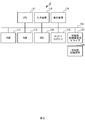
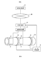
- FIG. 1 is a diagram schematically illustrating a piping diagnosis system according to an embodiment.
- FIG. 2 is a diagram illustrating an example of a hardware configuration of the information processing apparatus.
- FIG. 3 is a functional block diagram of the information processing apparatus.
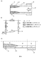
- FIG. 4A is a cross-sectional view showing an example of a pipe where deposits are deposited and thinned
- FIG. 4B is an equivalent modeled on the heat transfer behavior of the pipe shown in FIG.
- FIG. 4C illustrates a section represented by each element illustrated in FIG.
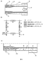
- FIG. 5A is a cross-sectional view showing another example of a pipe in which deposits are accumulated and thinned
- FIG. 5B models the heat transfer behavior of the pipe shown in FIG.
- FIG. 5A is a cross-sectional view showing another example of a pipe in which deposits are accumulated and thinned
- FIG. 5B models the heat transfer behavior of the pipe shown in FIG.
- FIG. 5A is a cross-sectional view showing another example of
- FIG. 5C shows an equivalent circuit, and shows a section represented by each element shown in FIG.
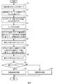
- FIG. 6 is a flowchart of piping diagnosis processing executed by the information processing apparatus.
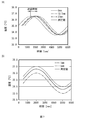
- FIG. 7A is a diagram for explaining the processing in step S21 in FIG. 6, and
- FIG. 7B is a diagram for explaining the processing in step S23 in FIG.
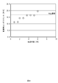
- FIG. 8 is a diagram for explaining the processing in step S25 of FIG.
- FIG. 9 is a diagram schematically showing a modification of the piping diagnosis system.
- FIG. 1 schematically shows the configuration of a piping diagnosis system 100 according to an embodiment.
- a piping diagnosis system 100 includes a temperature sensor 31 and a temperature detection device 33 as measurement devices, a heater 35 as a heating device, a heater control device 37, and an information processing device 10 as a piping diagnosis device. And comprising.
- the piping diagnostic system 100 measured a temperature change of the piping P10 calculated from a model in which the heat transfer behavior inside the piping P10 including deposits is modeled by an equivalent circuit when the piping P10 is heated by the heater 35. By comparing with the temperature change of the pipe, the accuracy of the model is improved, and the state of the pipe P10 is diagnosed using the model. More specifically, the piping diagnosis system 100 is derived from a periodic change in the surface temperature of the piping P10 when the output of the heater 35 is periodically changed and a periodic temperature change is given to the piping P10. By bringing the predetermined parameter closer to the predetermined parameter derived from the measured change in the periodic surface temperature of the pipe P10, a model suitable for the actual pipe condition is obtained, and the risk of thinning from the model is obtained. judge.
- the temperature sensor 31 is arranged on the surface of the pipe P10 so as to measure the surface temperature of the pipe P10 at a point away from the heater 35 in the length direction of the pipe.
- the output signal of the temperature sensor 31 is input to the temperature detection device 33.
- the temperature detection device 33 detects the temperature of the pipe P10 from the output signal of the temperature sensor 31, and outputs the detection result to the information processing device 10.
- the distance between the temperature sensor 31 and the heater 35 may be appropriately set in consideration of the performance of the heater 35, the thickness of the pipe P10, and the like. Further, the number of temperature sensors 31 may be one or plural.
- the heater control device 37 periodically changes the output of the heater 35 based on the output and the frequency f set by the information processing device 10 to be described later.
- the heater 35 periodically heats the pipe P10 at the frequency f under the control of the heater control device 37.
- the information processing apparatus 10 includes an equivalent circuit (model) that models the heat transfer behavior of the pipe P10, the shape of the pipe P10, the shape of the heater 35, the type of fluid that flows through the pipe P10, the fluid pressure, the fluid flow rate, and the outside. Accepts input of temperature data.
- the fluid pressure, the fluid flow rate, and the outside air temperature are input to the information processing apparatus 10 from a sensor (not shown) installed in the pipe P10.
- the information processing apparatus 10 determines the output of the heater 35 and the frequency f based on the received model and various data, and sets them in the heater control device 37.
- the information processing apparatus 10 displays the determined output and frequency f on the display device 119 and the like included in the information processing apparatus 10, and the user who confirms the display sets the output and frequency f in the heater control device 37. Also good.
- the information processing apparatus 10 When the information processing apparatus 10 periodically heats the pipe P10 with the output of the heater 35 and the frequency f determined by the information processing apparatus 10, the surface temperature of the pipe P10 calculated from the model of the heat transfer behavior of the pipe P10. Based on the periodic change and the periodic change of the surface temperature of the pipe P10 actually measured, the thickness of the deposit inside the pipe P10 and the thickness of the pipe P10 are calculated, and the model is updated. Get a model that fits the actual piping conditions. And the information processing apparatus 10 determines the thinning risk of the piping P10 using the updated model. Further, the information processing apparatus 10 notifies information related to ultrasonic diagnosis of the pipe P10 and information related to cleaning of the pipe P10 based on the determination result of the thinning risk.
- the information processing apparatus 10 has a hardware configuration as shown in FIG. Specifically, as shown in FIG. 2, the information processing apparatus 10 includes a central processing unit (CPU) 111, a read only memory (ROM) 112, a random access memory (RAM) 113, and a storage device (hard disk drive: HDD). ) 114, a network interface 115, a portable storage medium drive 117 capable of reading data stored in the portable storage medium 116, an input device 118, a display device 119, and the like. Each component of the information processing apparatus 10 is connected to the bus 120.
- the input device 118 is, for example, a keyboard, a mouse, a touch panel, or the like, but is not limited thereto.
- the CPU 111 causes the information processing apparatus 10 to function as each unit of FIG. 3 by executing a program stored in the ROM 112 or the HDD 114 or a program read from the portable storage medium 116 by the portable storage medium drive 117.
- the information processing apparatus 10 when the CPU 111 executes a program, the information processing apparatus 10 includes a data reception unit 11, a determination unit 12, a diagnosis unit 13, and a determination unit as a determination unit and a notification unit. 15 functions.
- the data reception unit 11 receives an input of an equivalent circuit (model) that models the heat transfer behavior of the pipe P10 from the user, for example, via the input device 118.
- an equivalent circuit that models the heat transfer behavior of the pipe P10 will be described.
- FIG. 4 (A) is a cross-sectional view showing an example of a pipe where deposits are accumulated and the thickness is reduced. It is assumed that the fluid flows in the pipe P11 in the direction indicated by the arrow A1.
- a heater 35 is attached to the upstream side of the pipe P11, and a temperature sensor 31 is attached to the downstream side.
- a deposit L10 is deposited on the downstream side of the pipe P11.
- FIG. 4A when the heat from the heater 35 and the heat transfer path through which the fluid flowing through the pipe P11 and the temperature sensor 31 are transmitted via the pipe P11 are represented by an equivalent circuit, for example, FIG. 4B is obtained.
- the model shown in FIG. 4B is a model of the lower half of the pipe P11 as shown in FIG. 4C.
- the fluid flowing inside the pipe P11 is deposited inside the pipe P11.
- the numbers described adjacent to each element in FIG. 4B represent each section in FIG. 4C that each element models.
- thermal conductance of the pipe P11 the thermal conductance of the deposit L10, and the thermal conductance of the fluid are obtained by the following equation (1).
- G thermal conductance
- ⁇ thermal conductivity
- A area
- L length (or thickness).
- the thermal conductance of the deposit L10 is applied to the corresponding location in the equivalent circuit shown in FIG.
- An element to be expressed is added to modify the equivalent circuit as shown in FIG. It is not necessary to create a model every time, and a model created for a certain pipe can be used for a pipe having the same unevenness or bending of the pipe. Furthermore, it is preferable to register the model as a database in a storage device such as the HDD 114.
- the data receiving unit 11 receives input of physical property data of piping from the user via the input device 118. Specifically, the data receiving unit 11 receives an input of the shape of the pipe, the shape of the heater 35, and the type of fluid flowing through the pipe from the user. The data receiving unit 11 receives inputs of fluid pressure, fluid flow rate, and outside air temperature from various sensors (not shown) installed in the pipe. The data reception unit 11 outputs the received model and various data to the determination unit 12 and the diagnosis unit 13. In addition, the data receiving unit 11 receives the surface temperature data of the pipe measured by the temperature sensor 31 from the temperature detection device 33 and outputs the data to the diagnosis unit 13.
- the determining unit 12 determines the output and the frequency f of the heater 35 based on the received model and various data, and sets them in the heater control device 37.
- the diagnostic unit 13 inputs various data to the model that models the heat transfer behavior of the pipe, and performs a thermal network analysis.
- the diagnostic unit 13 determines the time at the peak value within the period of the change in the surface temperature of the pipe calculated from the model when the pipe is heated periodically, and the period of the change in the surface temperature of the pipe measured by the temperature sensor 31.
- the thickness Ld of the deposit inside the pipe is calculated based on the delay time between the peak value and the peak value.
- diagnosis unit 13 is based on the peak value of the pipe surface temperature obtained from the model when the thickness of the deposit is Ld and the peak value of the actual surface temperature of the pipe measured by the temperature sensor 31. Then, the pipe thickness Lp is calculated. The diagnosis unit 13 outputs the calculated deposit thickness Ld and pipe thickness Lp to the determination unit 15.
- the determination unit 15 calculates the thermal conductance of the pipe in the model when the thickness of the deposit is Ld and the thickness of the pipe is Lp.
- the determination unit 15 compares the threshold registered in the threshold DB 16 with the calculated thermal conductance to determine whether there is a risk of thinning.
- the threshold value DB 16 stores a threshold value determined based on the thermal conductance of the piping when the piping is replaced in another similar piping system in the past. For example, when the calculated thermal conductance is equal to or greater than the threshold value, the determination unit 15 determines that there is a risk of thinning (the possibility that the pipe is thin enough to require replacement of the pipe). For example, if the determination unit 15 determines that there is a risk of thinning, the determination unit 15 notifies information related to ultrasonic diagnosis, and if not, notifies information related to pipe cleaning.
- FIG. 6 is a flowchart illustrating an example of piping diagnosis processing executed by the information processing apparatus 10.
- the process of FIG. 6 is performed regularly (every 6 months), for example. Note that the processing of FIG. 6 may be executed at a timing designated by an administrator of the piping facility, for example.
- a case will be described as an example in which a diagnosis is performed on the piping system A that has passed 6 years since the previous piping was replaced.
- the outer diameter of the piping is 100 mm
- the initial thickness is 5 mm
- the flow rate of water flowing through the piping measured by the flow sensor is 2 m / s.
- the flow velocity distribution of the water flowing in the pipe is uniform and the flow velocity is constant, and that the heat transfer of the pipe and the deposit is constant.
- the data receiving unit 11 receives an input of a model that models the heat transfer behavior of a pipe to be inspected (step S11).
- the data receiving unit 11 receives input of pipe shape data and heater shape data (step S13). Moreover, the data reception part 11 receives the input of sensor data (flow rate / pressure / outside temperature) (step S17).
- the determination unit 12 determines the output and cycle of the heater 35 (step S19). For example, the determination unit 12 determines the period of the heating cycle of the heater 35 as 6000 seconds. The heater 35 starts periodic heating of the pipe with the determined output and cycle.
- the diagnosis unit 13 compares the time in the peak value within the cycle of the change in the surface temperature of the pipe calculated from the heating cycle of the pipe and the model, and the peak value in the cycle of the change in the surface temperature of the measured pipe. Based on the delay time, the deposit thickness Ld in the element representing the thermal conductance of the deposit in the model is calculated (step S21). Specifically, the diagnosis unit 13 assumes that the pipe thickness Lp is an initial thickness of 5 mm, and changes the deposit thickness Ld to minimize the delay time between the model and the actual measurement. The length Ld is calculated. When deposits are accumulated inside the pipe, the way in which heat is transferred from the fluid flowing inside the pipe to the temperature sensor 31 is delayed, and a delay occurs in the peak within the heating cycle of the pipe. Can be used to calculate the thickness Ld.
- the diagnosis unit 13 determines the time at the peak value in the cycle of the temperature change of the surface temperature of the pipe when the thickness of the deposit is 0 mm, 13.5 mm, and 27 mm in the model, and the actually measured temperature. The delay time with respect to the time at the peak value within the period of change is calculated. The diagnosis unit 13 calculates the thickness Ld of the deposit that minimizes the delay time between the time at the peak value calculated from the model and the time at the actually measured peak value. For example, as shown in FIG. 7A, when the thickness of the deposit is assumed to be 0 mm, 13.5 mm, and 27 mm, the time at the peak value calculated from the model is 1500 seconds, 1875 seconds, and 2250, respectively. Suppose that it was seconds. In this case, when the time at the actually measured peak value is 2000 seconds, the diagnosis unit 13 calculates 18 mm as the thickness Ld of the deposit. Since the thickness Ld of the deposit is calculated based on the actually measured value, Ld with high accuracy can be calculated.
- the temperature waveform of the surface temperature of the pipe may be calculated with respect to the blockage rate of the pipe. For example, in the case of a pipe having an outer diameter of 100 mm and an initial thickness of 5 mm, if the deposit thickness is 13.5 mm, the blocking rate is 30%, and if the deposit thickness is 27 mm, the blocking rate is 60. %.
- the diagnosis unit 13 inputs the deposit thickness Ld calculated in step S21 into the model, and updates the model (step S22). Thereby, the state of the deposit actually deposited inside the pipe is reflected in the model. That is, since the model is updated to a model that matches the actual piping state, the accuracy of the model is improved.
- the diagnosis unit 13 uses the model based on the peak value of the surface temperature of the pipe calculated from the model to which the thickness Ld is input (reflected) and the peak value of the actual surface temperature of the measured pipe.
- the pipe thickness Lp in the element representing the thermal conductance of the pipe is calculated (step S23). Specifically, the diagnosis unit 13 changes the pipe thickness Lp to calculate the pipe thickness Lp that minimizes the difference between the peak value calculated from the model and the actually measured peak value. As the pipe is thicker, the heat from the heater 35 diffuses and the peak value of the pipe surface temperature becomes lower. Therefore, the peak value of the pipe surface temperature can be used to calculate the pipe thickness Lp.
- the diagnosis unit 13 calculates the peak value of the surface temperature of the pipe when the pipe thickness Lp is set to 1 mm and 5 mm in the model in which the deposit thickness Ld calculated in step S21 is input, for example. Then, the diagnosis unit 13 calculates the pipe thickness Lp that minimizes the difference between the peak value calculated from the model and the measured peak value of the actual surface temperature of the pipe. For example, as shown in FIG. 7B, the peak values of the surface temperature of the pipe calculated from the model when the pipe thickness Lp is 1 mm and 5 mm are 37.0 ° C. and 36.0 ° C., respectively. Suppose there was.
- the diagnosis unit 13 calculates approximately 3 mm as the pipe thickness Lp. Since the pipe thickness Lp is calculated based on the actually measured value, it is possible to calculate Lp with high accuracy.
- the diagnosis unit 13 inputs the pipe thickness Lp calculated in step S23 into the model, and updates the model (step S24). Thereby, the actual thinning state of the pipe is reflected in the model. That is, since the model is updated to a model that matches the actual piping state, the accuracy of the model is improved.
- step S21 and step S23 the model assumes that the flow velocity distribution of the fluid in the pipe is uniform and the flow velocity is constant, and that the heat transfer of the pipe and the deposit is also constant. Since it is assumed, there is a possibility that an error is included in the calculation result from the model. Therefore, it is preferable that the surface temperature data of the pipe is acquired by performing an experiment in the initial stage of the pipe installation without deposits. The calculation accuracy can be improved by correcting the value calculated from the model based on the experimental data.
- the determination unit 15 determines whether there is a risk of thinning (step S25). Specifically, in a model in which the deposit thickness Ld and the pipe thickness Lp are input (reflected), the thermal conductance of the pipe is calculated. The determination unit 15 determines that there is a risk of thinning when the calculated thermal conductance is equal to or greater than a threshold value registered in the threshold value DB 16. For example, as shown in FIG. 8, the thermal conductance of the pipe calculated when the pipe diagnosis process was performed every six months since the previous pipe was replaced did not exceed the threshold value of 17.0 W / K. This time (six years after pipe replacement), when calculating the thermal conductance of the pipe, it is assumed that it exceeded the threshold value of 17.0 W / K. In this case, the determination unit 15 determines that there is a risk of thinning.
- the determination unit 15 When it is determined that there is a risk of thinning (step S25 / YES), the determination unit 15 notifies information related to the ultrasonic diagnosis (step S27), and ends the process of FIG. For example, the determination unit 15 displays a message on the display device 119 of the information processing apparatus 10 that recommends performing ultrasound diagnosis. Thereby, the user (for example, manager of piping equipment) can secure equipment and personnel necessary for ultrasonic diagnosis.
- the information processing apparatus 10 is calculated from a model when the pipe is heated in a model in which the heat transfer behavior inside the pipe including deposits is modeled by an equivalent circuit.
- a diagnosis unit 13 for diagnosing the state of the pipe from the model updated based on the temperature change of the pipe and the temperature change of the pipe measured when the pipe is heated. Since the temperature change calculated from the model and the actually measured temperature change are used, the accuracy of the model is improved, and the diagnosis accuracy of the piping state using the model is also improved.
- the model includes a fluid flowing inside the pipe, deposits accumulated inside the pipe, and elements representing the pipe, and the diagnosis unit 13 starts from the model when the pipe is heated periodically.
- the state of deposits accumulated in the pipe based on the delay time between the calculated time at the peak value within the period of the temperature change of the pipe and the time at the peak value within the period of the measured temperature change of the pipe Is calculated.
- the delay time between the model and the actual measurement it is possible to calculate the state of the deposit accumulated on the pipe (the thickness of the deposit).
- the accuracy of the model is improved, and the diagnostic accuracy of the state of the pipe using the model is also improved.
- the diagnosis unit 13 updates the model in the state of the deposit accumulated on the calculated pipe, and the peak of the surface temperature of the pipe calculated from the model when the pipe is periodically heated. Based on the value and the peak value of the measured surface temperature of the pipe, the state of thinning of the pipe is calculated. By using the peak value calculated from the model and the actually measured peak value, it is possible to calculate the state of pipe thinning (pipe thickness). Thereby, the accuracy of the model is improved, and the diagnostic accuracy of the state of the pipe using the model is also improved.
- the information processing apparatus 10 updates the model in the calculated pipe thinning state, and determines the conductance value calculated from the updated model and the conductance value when the pipe is replaced.
- the determination part 15 which determines a thinning risk based on the determined threshold value is provided. Since the thinning risk is determined by comparison with the conductance value when the pipe has been replaced in the past, the thinning risk can be accurately determined.
- the determination unit 15 of the information processing apparatus 10 notifies information related to work on the pipe based on the diagnosed pipe state. Thereby, the user of the information processing apparatus 10 can assign tools and personnel necessary for ultrasonic diagnosis and cleaning of the piping.
- the pipe condition is calculated and reflected in the model, but the present invention is not limited to this.
- the pipe state is determined based on the change in the surface temperature of the pipe calculated from the model when the pipe is cooled and the change in the surface temperature of the pipe actually measured. It may be calculated and reflected in the model.
- the model can be adapted to the actual state of the piping by bringing the predetermined parameter value calculated from the model close to the actual measurement value.
- the information processing apparatus 10 may be a cloud.
- the worker is on the information processing apparatus 10 connected to the worker terminal 20 via a wired or wireless network NW, such as the Internet, Local Area Network (LAN), Wide Area Network (WAN), or the like. Diagnosis of piping can be performed by the service provided in.
- NW wireless or wireless network
- LAN Local Area Network
- WAN Wide Area Network
- the above processing functions can be realized by a computer.
- a program describing the processing contents of the functions that the processing apparatus should have is provided.
- the program describing the processing contents can be recorded on a computer-readable recording medium (except for a carrier wave).
- the program When the program is distributed, for example, it is sold in the form of a portable storage medium such as a DVD (Digital Versatile Disc) or CD-ROM (Compact Disc Read Only Memory) on which the program is recorded. It is also possible to store the program in a storage device of a server computer and transfer the program from the server computer to another computer via a network.
- a portable storage medium such as a DVD (Digital Versatile Disc) or CD-ROM (Compact Disc Read Only Memory) on which the program is recorded. It is also possible to store the program in a storage device of a server computer and transfer the program from the server computer to another computer via a network.
- the computer that executes the program stores, for example, the program recorded in the portable storage medium or the program transferred from the server computer in its own storage device. Then, the computer reads the program from its own storage device and executes processing according to the program. The computer can also read the program directly from the portable storage medium and execute processing according to the program. Further, each time the program is transferred from the server computer, the computer can sequentially execute processing according to the received program.
Landscapes
- Physics & Mathematics (AREA)
- General Physics & Mathematics (AREA)
- Life Sciences & Earth Sciences (AREA)
- Immunology (AREA)
- Biochemistry (AREA)
- Pathology (AREA)
- General Health & Medical Sciences (AREA)
- Health & Medical Sciences (AREA)
- Chemical & Material Sciences (AREA)
- Analytical Chemistry (AREA)
- Engineering & Computer Science (AREA)
- Ecology (AREA)
- Environmental Sciences (AREA)
- Biodiversity & Conservation Biology (AREA)
- Environmental & Geological Engineering (AREA)
- Mechanical Engineering (AREA)
- General Engineering & Computer Science (AREA)
- Investigating Or Analyzing Materials Using Thermal Means (AREA)
Abstract
L'invention concerne, afin de prédire l'état d'un tuyau de manière précise, un procédé de diagnostic de tuyau selon lequel un ordinateur exécute le traitement suivant. Dans un modèle dans lequel le comportement de transfert de chaleur à l'intérieur d'un tuyau contenant des sédiments est modélisé avec un circuit équivalent, l'état du tuyau est diagnostiqué à partir du modèle mis à jour sur la base des éléments suivants : un changement de température du tuyau qui est calculé à partir du modèle lorsque le tuyau est chauffé; et un changement de température du tuyau qui est mesuré lorsque le tuyau est chauffé.
Priority Applications (3)
| Application Number | Priority Date | Filing Date | Title |
|---|---|---|---|
| JP2020503159A JP7006766B2 (ja) | 2018-02-28 | 2018-02-28 | 配管診断方法、配管診断装置、及び配管診断システム |
| PCT/JP2018/007483 WO2019167166A1 (fr) | 2018-02-28 | 2018-02-28 | Procédé de diagnostic de tuyau, dispositif de diagnostic de tuyau et système de diagnostic de tuyau |
| US16/932,889 US20200348131A1 (en) | 2018-02-28 | 2020-07-20 | Method of diagnosing pipe, device of diagnosing pipe, and system of diagnosing pipe |
Applications Claiming Priority (1)
| Application Number | Priority Date | Filing Date | Title |
|---|---|---|---|
| PCT/JP2018/007483 WO2019167166A1 (fr) | 2018-02-28 | 2018-02-28 | Procédé de diagnostic de tuyau, dispositif de diagnostic de tuyau et système de diagnostic de tuyau |
Related Child Applications (1)
| Application Number | Title | Priority Date | Filing Date |
|---|---|---|---|
| US16/932,889 Continuation US20200348131A1 (en) | 2018-02-28 | 2020-07-20 | Method of diagnosing pipe, device of diagnosing pipe, and system of diagnosing pipe |
Publications (1)
| Publication Number | Publication Date |
|---|---|
| WO2019167166A1 true WO2019167166A1 (fr) | 2019-09-06 |
Family
ID=67805184
Family Applications (1)
| Application Number | Title | Priority Date | Filing Date |
|---|---|---|---|
| PCT/JP2018/007483 Ceased WO2019167166A1 (fr) | 2018-02-28 | 2018-02-28 | Procédé de diagnostic de tuyau, dispositif de diagnostic de tuyau et système de diagnostic de tuyau |
Country Status (3)
| Country | Link |
|---|---|
| US (1) | US20200348131A1 (fr) |
| JP (1) | JP7006766B2 (fr) |
| WO (1) | WO2019167166A1 (fr) |
Cited By (3)
| Publication number | Priority date | Publication date | Assignee | Title |
|---|---|---|---|---|
| JP2021518905A (ja) * | 2018-03-23 | 2021-08-05 | ローズマウント インコーポレイテッド | 非侵襲性パイプ壁診断法 |
| WO2022061228A1 (fr) * | 2020-09-18 | 2022-03-24 | Watlow Electric Manufacturing Company | Systèmes et procédés de détection de la présence de dépôts dans des conduits d'écoulement de fluide |
| TWI909139B (zh) * | 2021-09-22 | 2025-12-21 | 美商瓦特洛威電子製造公司 | 用於偵測流體流動導管中沉積物之存在之系統及方法 |
Families Citing this family (5)
| Publication number | Priority date | Publication date | Assignee | Title |
|---|---|---|---|---|
| KR101817083B1 (ko) * | 2016-06-03 | 2018-01-11 | 가천대학교 산학협력단 | 압전 센서의 구부림을 분석하는 장치 및 알고리즘 |
| CN114018981B (zh) * | 2021-09-28 | 2023-12-01 | 彩虹显示器件股份有限公司 | 一种铂金通道寿命的估算方法及系统 |
| JP7400790B2 (ja) * | 2021-10-06 | 2023-12-19 | 横河電機株式会社 | 推定装置、推定方法および推定プログラム |
| CN115930873A (zh) * | 2021-10-06 | 2023-04-07 | 横河电机株式会社 | 估计设备、估计方法以及计算机可读记录介质 |
| CN115631066B (zh) | 2022-12-22 | 2023-03-07 | 成都秦川物联网科技股份有限公司 | 智慧燃气管道冻胀安全管理方法和物联网系统 |
Citations (5)
| Publication number | Priority date | Publication date | Assignee | Title |
|---|---|---|---|---|
| JPS6126809A (ja) * | 1984-07-16 | 1986-02-06 | Showa Denko Kk | 流体管内の付着物状況検知方法および装置 |
| JPS6413445A (en) * | 1987-07-07 | 1989-01-18 | Fujitsu Ltd | Method for calculating thermal resistance of heat radiating route from surface packaging type element |
| JP2001176729A (ja) * | 1999-12-20 | 2001-06-29 | Mitsubishi Electric Corp | 電力機器負荷監視装置 |
| US6886393B1 (en) * | 1999-10-01 | 2005-05-03 | 01 Db Metravib | Method and device for detecting deposit in a conduit |
| JP2016024174A (ja) * | 2014-07-24 | 2016-02-08 | 国立大学法人埼玉大学 | 物質の熱拡散率測定方法およびその方法を使った物質の熱電特性評価装置 |
Family Cites Families (3)
| Publication number | Priority date | Publication date | Assignee | Title |
|---|---|---|---|---|
| JP2000161943A (ja) * | 1998-11-26 | 2000-06-16 | Hitachi Ltd | 配管の肉厚測定装置 |
| WO2009135504A1 (fr) * | 2008-05-07 | 2009-11-12 | Siemens Aktiengesellschaft | Dispositif et procédé pour détecter des dépôts |
| NO332832B1 (no) * | 2009-01-30 | 2013-01-21 | Statoil Asa | Fremgangsmate for a male tykkelsen av avsetninger |
-
2018
- 2018-02-28 WO PCT/JP2018/007483 patent/WO2019167166A1/fr not_active Ceased
- 2018-02-28 JP JP2020503159A patent/JP7006766B2/ja not_active Expired - Fee Related
-
2020
- 2020-07-20 US US16/932,889 patent/US20200348131A1/en not_active Abandoned
Patent Citations (5)
| Publication number | Priority date | Publication date | Assignee | Title |
|---|---|---|---|---|
| JPS6126809A (ja) * | 1984-07-16 | 1986-02-06 | Showa Denko Kk | 流体管内の付着物状況検知方法および装置 |
| JPS6413445A (en) * | 1987-07-07 | 1989-01-18 | Fujitsu Ltd | Method for calculating thermal resistance of heat radiating route from surface packaging type element |
| US6886393B1 (en) * | 1999-10-01 | 2005-05-03 | 01 Db Metravib | Method and device for detecting deposit in a conduit |
| JP2001176729A (ja) * | 1999-12-20 | 2001-06-29 | Mitsubishi Electric Corp | 電力機器負荷監視装置 |
| JP2016024174A (ja) * | 2014-07-24 | 2016-02-08 | 国立大学法人埼玉大学 | 物質の熱拡散率測定方法およびその方法を使った物質の熱電特性評価装置 |
Cited By (6)
| Publication number | Priority date | Publication date | Assignee | Title |
|---|---|---|---|---|
| JP2021518905A (ja) * | 2018-03-23 | 2021-08-05 | ローズマウント インコーポレイテッド | 非侵襲性パイプ壁診断法 |
| JP7101256B2 (ja) | 2018-03-23 | 2022-07-14 | ローズマウント インコーポレイテッド | 非侵襲性パイプ壁診断法 |
| WO2022061228A1 (fr) * | 2020-09-18 | 2022-03-24 | Watlow Electric Manufacturing Company | Systèmes et procédés de détection de la présence de dépôts dans des conduits d'écoulement de fluide |
| JP2023545633A (ja) * | 2020-09-18 | 2023-10-31 | ワットロー・エレクトリック・マニュファクチャリング・カンパニー | 流体流導管内の堆積物の存在を検出するためのシステムおよび方法 |
| US12347703B2 (en) | 2020-09-18 | 2025-07-01 | Watlow Electric Manufacturing Company | Systems and methods for detecting the presence of deposits in fluid flow conduits |
| TWI909139B (zh) * | 2021-09-22 | 2025-12-21 | 美商瓦特洛威電子製造公司 | 用於偵測流體流動導管中沉積物之存在之系統及方法 |
Also Published As
| Publication number | Publication date |
|---|---|
| JP7006766B2 (ja) | 2022-01-24 |
| US20200348131A1 (en) | 2020-11-05 |
| JPWO2019167166A1 (ja) | 2020-12-03 |
Similar Documents
| Publication | Publication Date | Title |
|---|---|---|
| JP7006766B2 (ja) | 配管診断方法、配管診断装置、及び配管診断システム | |
| JP6884448B2 (ja) | スケール厚さ推定システム、スケール厚さ推定方法、およびスケール厚さ推定プログラム | |
| Ahmad et al. | The exponentiated Weibull software reliability growth model with various testing‐efforts and optimal release policy: A performance analysis | |
| JP5901140B2 (ja) | システムの高い可用性のためにセンサデータを補間する方法、コンピュータプログラム、システム。 | |
| JP5985653B2 (ja) | 材料の熱物性値を推定するプロセス、該推定プロセスを含む測定プロセス、及び自己調整流量計 | |
| KR102914416B1 (ko) | 열교환 튜브 손상도 평가 장치 | |
| Thöns et al. | On damage detection system information for structural systems | |
| CN112525774B (zh) | 一种基于涡街流量计频谱的流速、密度和粘度的测量方法 | |
| Loyola-Fuentes et al. | Estimation of fouling model parameters for shell side and tube side of crude oil heat exchangers using data reconciliation and parameter estimation | |
| KR20140109596A (ko) | 미검침 구간의 검침 데이터 예측 및 보정 방법과 그 장치 | |
| EP4163587A1 (fr) | Dispositif d'estimation, procédé d'estimation et programme informatique d'estimation pour estimer une épaisseur de précipité | |
| WO2016174958A1 (fr) | Apparition de fuite d'eau, système, dispositif d'estimation de position et procédé | |
| JP2016086521A (ja) | 消費電力予測方法および装置 | |
| JP7014223B2 (ja) | 分析装置、診断装置、分析方法及びプログラム | |
| CN114692322B (zh) | 存储器、重油换热器结垢监测方法、装置和设备 | |
| JP5749422B2 (ja) | 流量計測方法 | |
| US11454529B2 (en) | Augmented flowmeter with a system for simulating fluid parameters | |
| Mazzotti et al. | Restrictions and obstructions detection in pipe networks using incomplete and noisy flow and pressure steady‐state measurements | |
| EP4350310A1 (fr) | Procédé mis en oeuvre par ordinateur pour déterminer des données de résistance thermique de limite, élément de produit informatique et système | |
| JP7780403B2 (ja) | 系統性能監視装置、および、系統性能監視方法 | |
| EP4350309A1 (fr) | Procédé mis en uvre par ordinateur pour déterminer des données de résistance thermique de limite, élément de produit informatique et système | |
| Xavier et al. | Automatic estimation of initial transient in a turbulent flow time series | |
| CN120344931A (zh) | 流体网络的整体多向异常和场景转变检测 | |
| JP6855953B2 (ja) | 配管診断方法、配管診断装置、及び配管診断システム | |
| JP2025094738A (ja) | 学習モデル生成装置、学習モデル生成プログラム、流量推定システム |
Legal Events
| Date | Code | Title | Description |
|---|---|---|---|
| 121 | Ep: the epo has been informed by wipo that ep was designated in this application |
Ref document number: 18907731 Country of ref document: EP Kind code of ref document: A1 |
|
| ENP | Entry into the national phase |
Ref document number: 2020503159 Country of ref document: JP Kind code of ref document: A |
|
| NENP | Non-entry into the national phase |
Ref country code: DE |
|
| 122 | Ep: pct application non-entry in european phase |
Ref document number: 18907731 Country of ref document: EP Kind code of ref document: A1 |