WO2019167202A1 - 配線ダクト用プラグ - Google Patents
配線ダクト用プラグ Download PDFInfo
- Publication number
- WO2019167202A1 WO2019167202A1 PCT/JP2018/007653 JP2018007653W WO2019167202A1 WO 2019167202 A1 WO2019167202 A1 WO 2019167202A1 JP 2018007653 W JP2018007653 W JP 2018007653W WO 2019167202 A1 WO2019167202 A1 WO 2019167202A1
- Authority
- WO
- WIPO (PCT)
- Prior art keywords
- plug
- electrode terminals
- movable electrode
- wiring duct
- movable
- Prior art date
- Legal status (The legal status is an assumption and is not a legal conclusion. Google has not performed a legal analysis and makes no representation as to the accuracy of the status listed.)
- Ceased
Links
Images






Classifications
-
- H—ELECTRICITY
- H01—ELECTRIC ELEMENTS
- H01R—ELECTRICALLY-CONDUCTIVE CONNECTIONS; STRUCTURAL ASSOCIATIONS OF A PLURALITY OF MUTUALLY-INSULATED ELECTRICAL CONNECTING ELEMENTS; COUPLING DEVICES; CURRENT COLLECTORS
- H01R35/00—Flexible or turnable line connectors, i.e. the rotation angle being limited
- H01R35/04—Turnable line connectors with limited rotation angle with frictional contact members
-
- H—ELECTRICITY
- H01—ELECTRIC ELEMENTS
- H01R—ELECTRICALLY-CONDUCTIVE CONNECTIONS; STRUCTURAL ASSOCIATIONS OF A PLURALITY OF MUTUALLY-INSULATED ELECTRICAL CONNECTING ELEMENTS; COUPLING DEVICES; CURRENT COLLECTORS
- H01R13/00—Details of coupling devices of the kinds covered by groups H01R12/70 or H01R24/00 - H01R33/00
- H01R13/66—Structural association with built-in electrical component
- H01R13/70—Structural association with built-in electrical component with built-in switch
- H01R13/71—Contact members of coupling parts operating as switch, e.g. linear or rotational movement required after mechanical engagement of coupling part to establish electrical connection
-
- H—ELECTRICITY
- H01—ELECTRIC ELEMENTS
- H01R—ELECTRICALLY-CONDUCTIVE CONNECTIONS; STRUCTURAL ASSOCIATIONS OF A PLURALITY OF MUTUALLY-INSULATED ELECTRICAL CONNECTING ELEMENTS; COUPLING DEVICES; CURRENT COLLECTORS
- H01R25/00—Coupling parts adapted for simultaneous co-operation with two or more identical counterparts, e.g. for distributing energy to two or more circuits
- H01R25/14—Rails or bus-bars constructed so that the counterparts can be connected thereto at any point along their length
- H01R25/142—Their counterparts
-
- H—ELECTRICITY
- H01—ELECTRIC ELEMENTS
- H01R—ELECTRICALLY-CONDUCTIVE CONNECTIONS; STRUCTURAL ASSOCIATIONS OF A PLURALITY OF MUTUALLY-INSULATED ELECTRICAL CONNECTING ELEMENTS; COUPLING DEVICES; CURRENT COLLECTORS
- H01R41/00—Non-rotary current collectors for maintaining contact between moving and stationary parts of an electric circuit
Definitions
- the present invention relates to a plug for a wiring duct used by being attached to a wiring duct laid on a ceiling.
- a plug 1 that is electrically and mechanically connected to a distribution duct 20 in which a plurality of conductors 21 are housed.
- An insertion portion 2 that is inserted into the distribution duct 20 and locked to the distribution duct 20.
- the plug body 4 includes an exposed portion 3 that is connected to the insertion portion 2 and is exposed to the outside of the distribution duct 20.
- the conductive portion 11 that can be electrically connected to an arbitrary conductor 21 is provided in the insertion portion 2.
- An electrical switching means 10 is provided in the plug body 4 to switch an arbitrary conductor 21 and electrically connect to the conductive portion 11.
- the present invention has been made in view of the above-described circumstances, and an object thereof is to provide a wiring duct plug that does not have a movable part for switching and therefore has high operational reliability.
- the present invention is a wiring duct plug that is used by being attached to a wiring duct in which a plurality of conductive wires are laid, and is a rotatable rotating body, a pair of stationary electrode terminals, and a rotating A plurality of movable electrode terminals that rotate together with the body and electrically connect a plurality of conductors and a pair of stationary electrode terminals and a release position that electrically releases the connection;
- the plurality of movable electrode terminals one or more of the plurality of movable electrode terminals is connected to one or more conductors less than the plurality of conductors and the base end portion is joined to one.
- the remaining movable electrode terminal is connected to the other stationary electrode terminal, and the remaining movable electrode terminal is connected to the other stationary electrode terminal.
- the plurality of movable electrode terminals are joined together at the base end side. Therefore, the plurality of movable electrode terminals electrically connect the plurality of conductive wires and one stationary electrode terminal at the connection position. For this reason, for example, the plurality of movable electrode terminals can be electrically connected to one of the non-moving electrode terminals without selecting one of the plurality of conductive wires. That is, a movable part for selecting (switching) one conductor from a plurality of conductors is not necessary, and the operation reliability can be improved correspondingly. The remaining movable electrode terminal connects the remaining conductive wire and the other stationary electrode terminal.
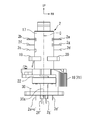
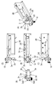
- FIG. 2 is a perspective view of a plug 2.
- FIG. 3 is a front view of the plug 2.
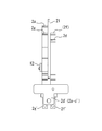
- FIG. 4 is a right side view in which a part of the plug 2 is omitted.
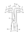
- 4 is a front view for explaining an insulating wall 21, movable electrode terminals 2a to 2d, movable signal terminals 2f and 2g, stationary electrode terminals 2a-c ′ and 2d ′, and stationary signal terminals 2f ′ and 2g ′ of the plug 2.
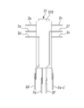
- FIG. 6 is a rear view illustrating the insulating wall 21, the movable electrode terminals 2a to 2d, the movable signal terminals 2f and 2g, the stationary electrode terminals 2a-c ′ and 2d ′, and the stationary signal terminals 2f ′ and 2g ′ of the plug 2. It is a right view explaining the insulating wall 21, the movable electrode terminals 2a, 2d, the movable signal terminal 2g, the stationary electrode terminal 2d ', and the stationary signal terminals 2f', 2g 'of the plug 2.
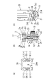
- 7A is a cross-sectional view orthogonal to the longitudinal direction of the wiring duct 1A, and FIG.
- FIG. 7B is a schematic front view for explaining the movable electrode terminals 1a to 1d and the stationary electrode terminals 1a-c ′ and 1d ′ of the plug 1.
- FIG. 7C is a schematic plan view illustrating the movable electrode terminals 1a, 1b, and 1d of the plug 1.
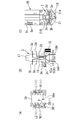
- FIG. 8A is a cross-sectional view orthogonal to the longitudinal direction of the wiring duct 2A
- FIG. 8B is a movable electrode terminal 2a to 2d, movable signal terminals 2f and 2g, and stationary electrode terminals 2a-c 'and 2d of the plug 2.
- the stationary signal terminals 2f' and 2g are schematic front views.
- FIG. 8C is a schematic plan view illustrating the movable electrode terminals 2a, 2b and 2d of the plug 2 and the movable signal terminal 2f.
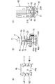
- 9A is a cross-sectional view orthogonal to the longitudinal direction of the wiring duct 3A
- FIG. 9B illustrates the movable electrode terminals 3a, 3b, 3d, and 3e and the stationary electrode terminals 3ab ′ and 3de ′ of the plug 3.
- FIG. 9C is a schematic plan view illustrating the movable electrode terminals 3a, 3b, 3d, and 3e of the plug 3.
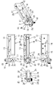
- FIG. 10A is a cross-sectional view orthogonal to the longitudinal direction of the wiring duct 4A, and FIG.
- FIG. 10B illustrates the movable electrode terminals 4a, 4b, 4d, and 4e and the stationary electrode terminals 4ab ′ and 4de ′ of the plug 4.
- FIG. 10C is a schematic plan view illustrating the movable electrode terminals 4a, 4b, 4d, and 4e of the plug 4.
- FIG. 11A is a perspective view for explaining the plug 1 used in the wiring duct 1A of FIG. 7A
- FIG. 11B is a plan view
- FIG. 11C is a right side view
- FIG. (D) is a left side view
- FIG. 11 (E) is a front view.
- 12A is a perspective view for explaining the plug 2 used in the wiring duct 2A of FIG. 8A
- FIG. 12B is a plan view
- FIG. 12A is a perspective view for explaining the plug 2 used in the wiring duct 2A of FIG. 8A
- FIG. 12B is a plan view
- FIG. 12A is a perspective view for explaining the plug
- FIG. 12C is a right side view
- FIG. (D) is a left side view
- FIG. 12 (E) is a front view
- 13A is a perspective view for explaining the plug 3 used in the wiring duct 3A of FIG. 9A
- FIG. 13B is a plan view
- FIG. 13C is a right side view
- FIG. (D) is a left side view
- FIG. 13 (E) is a front view
- 14A is a perspective view for explaining the plug 4 used in the wiring duct 4A of FIG. 10A
- FIG. 14B is a plan view
- FIG. 14C is a right side view
- FIG. (D) is a left side view
- FIG. 14 (E) is a front view.
- FIG. 14A is a perspective view for explaining the plug 4 used in the wiring duct 4A of FIG. 10A
- FIG. 14B is a plan view
- FIG. 14C is a right side view
- FIG. (D) is a left side view
- FIG. 15A is an enlarged view of the wiring duct 1A of FIG. 7A
- FIG. 15B is an enlarged view of the wiring duct 2A of FIG. 8A
- 16A is a right side view of the plug 2
- FIG. 16B is a view taken along the line AA in FIG. 16A
- FIG. 16C is a line BB in FIG. 16A.
- 17A is a perspective view showing the insulating wall 21 of the plug 4, the movable electrode terminals 4a and 4b on the front surface side 21A, and the movable electrode terminals 4d and 4e on the rear surface side 21B.
- FIG. Similarly, it is a left side view.
- a wiring duct plug (hereinafter simply referred to as a plug) 1 to 4 according to a first embodiment to which the present invention is applied will be described with reference to FIGS.
- reference symbols UP, FR, and RH indicated by arrows in FIGS. 1 to 3 indicate the upper, front, and right sides of the plug 2 in this order.
- an outline of the four plugs 1 to 4 will be described.
- the plug 1 is, for example, a plug used for a wiring duct 1A (see FIG. 7A) of Company A for Europe / Asia (hereinafter referred to as CE specifications). The plug 1 will be described later with reference to FIGS.
- the plug 1 has four movable electrode terminals 1a to 1d. Of these, the three movable electrode terminals 1a to 1c are disposed on the front surface side 21A of the insulating wall 21, and the base end portion K1 is joined to one to electrically connect to one of the stationary electrode terminals 1a-c '. Connected to. The remaining movable electrode terminal 1d is disposed on the rear surface side 21B of the insulating wall 21 and is electrically connected to the other stationary electrode terminal 1d ′.
- the plug 2 is, for example, a plug used for a wiring duct 2A (see FIG. 8A) of CE specification B company (different from company A). The plug 2 will be described later with reference to FIGS.
- the plug 2 has four movable electrode terminals 2a to 2d. Of these, the three movable electrode terminals 2a to 2c are disposed on the front surface side 21A of the insulating wall 21, and the base end portion K2 is joined to one to electrically connect to one of the stationary electrode terminals 2a-c '. Connected to.
- the plug 2 has two movable signal terminals 2f and 2g.
- the movable signal terminal 2g is disposed on the front surface 21A of the insulating wall 21 and is electrically connected to the stationary signal terminal 2g ′.
- the remaining movable signal terminal 2f is disposed on the rear surface side 21B of the insulating wall 21 and is electrically connected to the stationary signal terminal 2f ′.
- the plug 3 is, for example, a plug used for a wiring duct 3A (see FIG. 9A) of Company A for the United States and Canada (hereinafter referred to as UL specification). The plug 3 will be described later with reference to FIGS. 9 and 13.
- the plug 3 has four movable electrode terminals 3a, 3b, 3d, and 3e.
- the two movable electrode terminals 3a and 3b are disposed on the front surface side 21A of the insulating wall 21, and the base end portion K3a is joined together to be electrically connected to one of the stationary electrode terminals 3ab '. Is done.
- the remaining two movable electrode terminals 3d and 3e are disposed on the rear surface side 21B of the insulating wall 21, and the base end K3b is joined to one to be electrically connected to the other stationary electrode terminal 3de '. Is done.
- the plug 4 is, for example, a plug used for a wiring duct 4A (see FIG. 10A) of Company B of UL specification.
- the plug 4 will be described later with reference to FIGS. 10 and 14.
- the plug 4 has four movable electrode terminals 4a, 4b, 4d, and 4e.
- the two movable electrode terminals 4a and 4b are disposed on the front surface side 21A of the insulating wall 21, and the base end portion K4a is joined to one to be electrically connected to one of the stationary electrode terminals 4ab '. Is done.
- the remaining two movable electrode terminals 4d and 4e are disposed on the rear surface side 21B of the insulating wall 21, and the base end K4b is joined to one to be electrically connected to the other non-moving electrode terminal 4de '. Is done.
- the four plugs 1 to 4 will be described.
- the plug 2 will be described in detail with reference to FIGS.
- FIG. 1 is a perspective view of the plug 2.
- FIG. 2 is a front view of the plug 2.
- FIG. 3 is a right side view in which a part of the plug 2 is omitted.
- the plug 2 is used by being attached to the wiring duct 2A shown in FIG.
- FIG. 8A is a cross-sectional view orthogonal to the longitudinal direction of the wiring duct 2A.
- the wiring duct 2A is, for example, a wiring duct of company B with CE specifications.
- the wiring duct 2A has a rectangular cross section and has an opening 2Aa at the bottom.
- a conductor L1 (+) is disposed on the right side of the upper inner side
- a conductor L2 (+) is disposed on the left side
- a signal line DB (+) is disposed on the left side of the middle stage
- a signal is disposed on the right side.
- a line DB ( ⁇ ) is disposed, and a conductor L3 (+) is disposed on the left side of the lower stage, and a conductor N1 ( ⁇ ) is disposed on the right side.
- rail portions R and R are laid on the left and right sides of the opening 2Aa, respectively.
- FIG. 4 illustrates the insulating wall 21, the movable electrode terminals 2a to 2d, the movable signal terminals 2f and 2g, the stationary electrode terminals 2a-c ′ and 2d ′, and the stationary signal terminals 2f ′ and 2g ′ of the plug 2.
- FIG. 5 illustrates the insulating wall 21, the movable electrode terminals 2a to 2d, the movable signal terminals 2f and 2g, the stationary electrode terminals 2a-c ′ and 2d ′, and the stationary signal terminals 2f ′ and 2g ′ of the plug 2. It is a rear view.
- FIG. 5 illustrates the insulating wall 21, the movable electrode terminals 2a to 2d, the movable signal terminals 2f and 2g, the stationary electrode terminals 2a-c ′ and 2d ′, and the stationary signal terminals 2f ′ and 2g ′ of the plug 2. It is a rear view.
- FIG. 5 illustrates the insulating wall 21, the movable
- FIG. 6 is a right side view illustrating the insulating wall 21, the movable electrode terminals 2a and 2d, the movable signal terminal 2g, the stationary electrode terminal 2d ′, and the stationary signal terminals 2f ′ and 2g ′ of the plug 2. That is, FIG. 4 to FIG. 6 are a front view, a rear view, and a right side view showing the structure of the inner side (inner space) of the rotating body 17 and the stationary terminal support 30 described later.
- the plug 2 includes a rotating body 17, a pair of stationary electrode terminals 2a-c ′ and 2d ′, and a plurality of movable electrode terminals 2a, 2b, 2c and 2d.
- the “immobility” of the stationary electrode terminals 2a-c ′ and 2d means that the position hardly changes with respect to the adapter 2B.
- the “movable” of the movable electrode terminals 2a to 2d means the adapter 2B. In contrast, the position changes (rotates approximately 90 degrees).
- the rotating body 17 is rotatable around a rotation axis C directed in the vertical direction.
- a substantially rectangular parallelepiped adapter 2B that is long in the front-rear direction and thin in the left-right direction is disposed behind the rotating body 17.
- Two claw members 13 and 14 are arranged on the left wall surface 11 of the adapter 2B, and two claw members 15 and 16 are arranged on the right wall surface 12. Yes.
- the claw members 13 to 16 have flat bottom surfaces that ride on the rail portions R and R in FIG. 8A, and protrude from the left and right wall surfaces 11 and 12 so as to freely enter and exit.
- a support portion 22 extending forward is formed in the lower portion of the adapter 2B.
- the rotating body 17 is rotatably supported by the support portion 22.
- the rotating body 17 has engaging pieces 19 and 20 extending in the left-right direction at the center in the vertical direction, and an operation lever 18 at the lower part in the vertical direction.
- the operation lever 18 is disposed at the connection position R1 shown in FIGS. 1 to 3, the bent portion P on the distal end side of the movable electrode terminals 2a to 2d and the engagement pieces 19 and 20 are positioned substantially in the left-right direction. .
- the operation lever 18 is rotated approximately 90 degrees in the direction of the arrow M1 in FIG.
- the movable electrode terminals 2a to 2d and the engagement pieces 19 and 20 are substantially directed in the front-rear direction.
- the operation lever 18 arranged at the release position almost 90 degrees in the direction of the arrow M2, it can be arranged again at the connection position R1.
- connection position the position of the movable electrode terminals 2a to 2d corresponding to the connection position R1 of the operation lever 18 facing the substantially left-right direction
- release position the position of the movable electrode terminals 2a to 2d facing substantially the front-rear direction.
- the movable electrode terminals 2a to 2d will be described in detail later.
- a stationary terminal support portion 30 is disposed below the support portion 22 of the adapter 2B. As shown in FIG. 1, for example, the fixed terminal support portion 30 is configured such that the outer diameter of a bolt member (not shown) passed through the screw hole 22a of the support portion 22 hits the abutment portion 30a. Is immobile. A pair of plate-like stationary electrode terminals 2 a-c ′ and 2 d ′ and stationary signal terminals 2 f ′ and 2 g ′ are fixed inside the stationary terminal support portion 30.
- the internal space of the rotating body 17 is formed in a substantially cylindrical shape.
- the insulating wall 21 shown in FIGS. 4 to 6 is arranged in the up-down direction with the insulating wall 21 facing in the left-right direction, and the internal space is divided into front and rear.
- a plurality of movable electrode terminals 2a to 2d and a plurality of movable signal terminals 2f and 2g are arranged.
- the three movable electrode terminals 2a to 2c are arranged on the front side (one side) 21A with the insulating wall 21 in between.
- the movable electrode terminal 2a is disposed on the upper right side
- the movable electrode terminal 2b is disposed on the upper left side
- the movable electrode terminal 2c is disposed on the lower left side. Yes.
- the three movable electrode terminals 2a to 2c are joined together at the base end (lower end) K2. Then, after being joined together, they are connected to the above-mentioned stationary electrode terminals 2a-c ′ at the connection position shown in FIG.
- the remaining movable electrode terminals 2d among the plurality of movable electrode terminals 2a to 2d are arranged on the rear surface (the other side) 21B side with the insulating wall 21 interposed therebetween.
- the movable electrode terminal 2d is disposed on the lower right side.
- the movable electrode terminal 2d is connected to the above-described stationary electrode terminal 2d ′ at the connection position shown in FIG.
- the movable signal terminal 2g is disposed on the front side (one side) 21A with the insulating wall 21 in between.
- the movable signal terminal 2g is arranged on the right side of the middle stage.
- the proximal end side of the movable signal terminal 2g is connected to the above-described stationary signal terminal 2g ′ at the connection position shown in FIG.
- the movable signal terminal 2f is disposed on the rear surface (the other side) 21B side with the insulating wall 21 interposed therebetween.
- the movable signal terminal 2f is disposed on the left side of the middle stage.
- the proximal end side of the movable signal terminal 2f is connected to the above-described stationary signal terminal 2f ′ at the connection position shown in FIG.
- the plug 2 having the above-described configuration shown in FIGS. 1 to 3 is used by being attached to the wiring duct 2A shown in FIG.
- the operation lever 18 of the plug 2 is rotated approximately 90 degrees from the connection position R1 in the direction of the arrow M1, and is arranged at the release position. Accordingly, the movable electrode terminals 2a to 2d, the movable signal terminals 2f and 2g, and the engagement pieces 19 and 20 are directed in the front-rear direction.
- the front-rear direction of the plug 2 is aligned with the longitudinal direction of the wiring duct 2A, and the upper side of the plug 2 is inserted from the opening 2Aa of the wiring duct 2A.
- the claw members 13 to 16 ride on the rail portions R and R and support the entire plug 2.
- the operation lever 18 When removing the plug 2 from the wiring duct 2A, the operation lever 18 is rotated from the connection position R1 in the direction of the arrow M1. As a result, a part of the rotating body 17 can push the interlocking mechanism 23 between the rotating body 17 and the adapter 2B rearward to forcibly retract the claw members 13 to 16 to the left and right wall surfaces 11 and 12. ing.
- the operation lever 18 is rotated in the direction of the arrow M2 to return to the original connection position R1.
- the movable electrode terminals 2a to 2c electrically connect the conductive wires L1 (+) to L3 (+) and the stationary electrode terminal 2a-c '
- the movable electrode terminal 2d is connected to the conductive wire N1 (-).
- the stationary electrode terminal 2d ′ are electrically connected to the stationary electrode terminal 2d ′.
- the movable signal terminal 2f electrically connects the signal line DB (+) and the stationary signal terminal 2f ′
- the movable signal terminal 2g connects the signal line DB ( ⁇ ) and the stationary signal terminal 2g ′.
- the plug 2 does not necessarily need to be integrated with the adapter 2B.
- the actions and effects of the plug 2 described mainly with reference to FIGS. 1 to 6, 8, and 12 will be summarized.
- the plurality of movable electrode terminals 2a to 2c are joined together at the base end K2. Therefore, the plurality of movable electrode terminals 2a to 2c electrically connect the plurality of conductive wires L1 (+) to L3 (+) and one stationary electrode terminal 2a-c ′ at the connection position. For this reason, for example, the plurality of movable electrode terminals 2a to 2c can be selected by any of the conductive wires L1 (+) to L3 (+) without selecting one of the multiple conductive wires L1 (+) to L3 (+). Even if it exists, it can be electrically connected to one of the stationary electrode terminals 2a-c ′.
- the remaining movable electrode terminal 2d connects the remaining conductive wire N1 ( ⁇ ) to the other stationary electrode terminal 2d ′.
- the rotating body 17 includes the insulating wall 21 that bisects the internal space, and the movable electrode terminals 2a to 1 are one or more fewer than the plurality of conducting wires L1 (+) to L3 (+) and N1 ( ⁇ ).
- 2c is disposed on the front side (one side) 21A of the internal space with the insulating wall 21 in between, and the remaining movable electrode terminal 2d is disposed on the rear side (the other side) 21B in the internal space with the insulating wall 21 in between. ing. Therefore, for example, the + side movable electrode terminals 2 a to 2 c and the ⁇ side movable electrode terminal 2 d can be exactly separated by the insulating wall 21.
- the plurality of movable electrode terminals 2a to 2d have the deformation center O in the vicinity of the base end portion, and it is possible to ensure a long distance from the bending portion P at the distal end to the deformation center O. it can. Therefore, the stroke S of the bent portion P of the movable electrode terminals 2a to 2d can be made large, and the movable electrode terminals 2a to 2d can be arranged at the contact positions with a relatively small force.
- the plug 2 has a pair of movable signal terminals 2f and 2g in addition to the plurality of movable electrode terminals 2a to 2d, the plurality of movable electrode terminals 2a to 2d, and the pair of movable signal terminals 2f, 2 g are all disposed in a narrow internal space of the rotating body 17.
- one movable signal terminal 2g is disposed on the front surface side (one side) 21A of the insulating wall 21, and the other movable signal terminal 2f is disposed on the rear surface side (the other side) 21B of the insulating wall 21.
- the insulating wall 21 can separate the one movable signal terminal 2g from the other movable signal terminal 2f.
- the pair of movable signal terminals 2f and 2g have the deformation center O in the vicinity of the base end portion, and can ensure a long distance from the bending portion P to the deformation center O at the distal end. .
- the stroke S of the bent portion P of the movable signal terminals 2f and 2g can be made large, and the movable signal terminals 2f and 2g can be arranged at the contact position with a relatively small force.
- FIG. 7A is a cross-sectional view orthogonal to the longitudinal direction of the wiring duct 1A
- FIG. 7B shows the movable electrode terminals 1a to 1d of the plug 1 and the stationary electrode terminals 1a-c ′
- FIG. 7C is a schematic plan view illustrating the movable electrode terminals 1a, 1b, and 1d of the plug 1.
- FIG. 7B the insulating wall 21 is omitted.
- FIG. 8A is a cross-sectional view orthogonal to the longitudinal direction of the wiring duct 2A.
- FIG. 8B shows the movable electrode terminals 2a to 2d, the movable signal terminals 2f and 2g, and the stationary electrode terminals of the plug 2.
- FIG. 8C is a schematic front view for explaining 2a-c ′, 2d ′ and immobile signal terminals 2f ′, 2g ′.
- FIG. 8C is a diagram showing movable electrode terminals 2a, 2b, 2d and movable signal terminal 2f of plug 2. It is a plane schematic diagram explaining these.
- the insulating wall 21 is omitted.
- FIG. 9A is a cross-sectional view orthogonal to the longitudinal direction of the wiring duct 3A
- FIG. 9B shows the movable electrode terminals 3a, 3b, 3d, 3e of the plug 3 and the stationary electrode terminal 3ab ′.
- 3de ′ shows the movable electrode terminals 3a, 3b, 3d, and 3e of the plug 3.
- FIG. 9B the insulating wall 21 is omitted.
- FIG. 10A is a cross-sectional view orthogonal to the longitudinal direction of the wiring duct 4A.
- FIG. 10B shows the movable electrode terminals 4a, 4b, 4d and 4e of the plug 4 and the stationary electrode terminal 4ab ′.
- FIG. 10C is a schematic plan view illustrating the movable electrode terminals 4a, 4b, 4d, and 4e of the plug 4.
- the insulating wall 21 is omitted.
- the wiring duct 1A shown in FIG. 7 (A) is a CE specification company A wiring duct as described above.
- the conductors L1 (+) and L2 (+) are disposed on the inner upper stage, and the conductors L3 (+) and N1 ( ⁇ ) are disposed on the lower stage.
- signal lines DB (+) and DB ( ⁇ ) are arranged further below the lower stage on the left side.
- a plug 1 shown in FIGS. 7B and 7C is attached to the wiring duct 1A.
- the engagement pieces 19 and 20 come from below the wiring duct 1 ⁇ / b> A, and the conductive wires L ⁇ b> 1 (+), L ⁇ b> 2 (+), and L ⁇ b> 3 (+) contact the movable electrode terminals 1 a, 1 b, and 1 c in this order.
- the conducting wire N1 ( ⁇ ) contacts the movable electrode terminal 1d.
- These movable electrode terminals 1a, 1b, and 1c are joined at the base end portion K1, and are arranged on the front side 21A with an insulating wall 21 that bisects the inside of the rotating body 17 in the front and rear directions.
- the movable electrode terminal 1d is disposed on the rear surface side 21B of the insulating wall 21.
- the signal lines DB (+) and DB ( ⁇ ) are in contact with signal terminals 1m and 1n having different shapes arranged outside the rotating body 17.
- the wiring duct 2A shown in FIG. 8 (A) is a CE specification company B wiring duct as described above.
- the wiring duct 2A has conductors L1 (+) and L2 (+) arranged in the upper stage along the longitudinal direction, signal lines DB (+) and DB ( ⁇ ) arranged in the middle stage, and Conductor wires L3 (+) and N1 ( ⁇ ) are arranged on the lower stage.
- the plug 2 shown in FIGS. 8B and 8C is attached to the wiring duct 2A.
- the engagement pieces 19 and 20 come from below the wiring duct 2 ⁇ / b> A, and the conductive wires L ⁇ b> 1 (+), L ⁇ b> 2 (+), and L ⁇ b> 3 (+) contact the movable electrode terminals 2 a, 2 b, 2 c in this order.
- the conducting wire N1 ( ⁇ ) contacts the movable electrode terminal 2d.
- These movable electrode terminals 2a, 2b, and 2c are joined to one base end portion K2, and are arranged on the front side 21A with an insulating wall 21 that bisects the inside of the rotating body 17 in the front-rear direction.
- the movable electrode terminal 2d is disposed on the rear surface side 21B of the insulating wall 21.
- the signal lines DB (+) and DB ( ⁇ ) are in contact with the movable signal terminals 2f and 2g, respectively.
- the movable signal terminal 2f is on the rear surface side 21B of the insulating wall 21, and the movable signal terminal 2g is The insulating wall 21 is disposed on the front side 21A.
- the wiring duct 3A shown in FIG. 9 (A) is a UL-specification company A wiring duct as described above.
- the wiring duct 3A has conductors L1 (+) and L2 (+) disposed on the inner upper stage along the longitudinal direction, and conductors N1 ( ⁇ ) and N2 ( ⁇ ) disposed on the lower stage. Further, signal lines DB (+) and DB ( ⁇ ) are arranged further below the lower stage on the left side.
- a plug 3 shown in FIGS. 9B and 9C is attached to the wiring duct 3A.
- the engagement pieces 19 and 20 come from below the wiring duct 3 ⁇ / b> A, and the lead L ⁇ b> 1 (+) contacts the movable electrode terminal 3 a and the lead L ⁇ b> 2 (+) contacts the movable electrode terminal 3 b.
- the conductive wire N1 ( ⁇ ) contacts the movable electrode terminal 3d
- the conductive wire N2 ( ⁇ ) contacts the movable electrode terminal 3e.
- These movable electrode terminals 3a and 3b are joined to one base end portion K3a, and are arranged on the front side 21A with the insulating wall 21 in between.
- the movable electrode terminals 3d and 3e are joined to one base end portion K3b, and are arranged on the rear surface side 21B with the insulating wall 21 interposed therebetween.
- the signal lines DB (+) and DB ( ⁇ ) are in contact with signal terminals 3m and 3n having different shapes arranged outside the rotating body 17.
- the wiring duct 4A shown in FIG. 10A is a UL-specification company B wiring duct as described above.
- the conductors L1 (+) and L2 (+) are disposed on the inner upper stage, and the conductors N1 ( ⁇ ) and N2 ( ⁇ ) are disposed on the lower stage.
- a plug 4 shown in FIGS. 10B and 10C is attached to the wiring duct 4A.
- the engagement pieces 19 and 20 come from below the wiring duct 4 ⁇ / b> A
- the conductive wire L ⁇ b> 1 (+) contacts the movable electrode terminal 4 a
- the conductive wire L ⁇ b> 2 (+) contacts the movable electrode terminal 4 b.
- the conductive wire N1 ( ⁇ ) contacts the movable electrode terminal 4d
- the conductive wire N2 ( ⁇ ) contacts the movable electrode terminal 4e.
- These movable electrode terminals 4a and 4b are joined to one base end portion K4a and arranged on the front side 21A with the insulating wall 21 in between.
- the movable electrode terminals 4d and 4e are joined to one base end portion K4b, and are arranged on the rear surface side 21B with the insulating wall 21 interposed therebetween.
- the plugs 1 to 4 used in the wiring ducts 1A to 4A will be further described with reference to FIGS.
- FIG. 11A is a perspective view illustrating the plug 1 used in the wiring duct 1A of FIG. 7A
- FIG. 11B is a plan view
- FIG. 11C is a right side view
- FIG. 11 (D) is a left side view
- FIG. 11 (E) is a front view.
- FIG. 12A is a perspective view illustrating the plug 2 used in the wiring duct 2A of FIG. 8A
- FIG. 12B is a plan view
- FIG. 12C is a right side view
- 12D is a left side view
- FIG. 12E is a front view.
- FIG. 13A is a perspective view for explaining the plug 3 used in the wiring duct 3A of FIG. 9A
- FIG. 13B is a plan view
- FIG. 13C is a right side view
- FIG. 13D is a left side view
- FIG. 13E is a front view.
- FIG. 14A is a perspective view illustrating the plug 4 used in the wiring duct 4A of FIG. 10A
- FIG. 14B is a plan view
- FIG. 14C is a right side view
- 14D is a left side view
- FIG. 14E is a front view.
- the plug 1 is formed integrally with an adapter 1B used in the wiring duct 1A shown in FIG. 7A.
- the adapter 1B is formed in a rectangular parallelepiped shape that is long in the front-rear direction (same as the longitudinal direction of the wiring duct 1A), and claw members 13 to 16 that can enter and exit are disposed on the left and right wall surfaces 11 and 12, respectively.
- the adapter 1B is hung at the mounting position of the wiring duct 1A with the claw members 13 to 16 being hooked on the rail portions R and R of the wiring duct 1A so that the upper side is placed inside the wiring duct 1A. .
- the plug 1 is rotatably supported by the adapter 1B.
- the plug 1 includes a substantially cylindrical rotating body 17 having a rotation axis C (see FIG. 1) directed in the vertical direction, and an operation lever 18 fixed near the lower end thereof.
- the movable electrode terminals 1a to 1d protrude from the rotating body 17.
- the movable electrode terminals 1a and 1b protrude in the left-right direction from the upper stage of the rotator 17, and the movable electrode terminals 1c and 1d extend in the left-right direction from the lower stage. From the lower side of the movable electrode terminals 1c and 1d, the engagement pieces 19 and 20 extend in the left-right direction at substantially the same height as the claw members 13 to 16 described above.
- the movable electrode terminals 1a to 1c are located on the front side 21A of the insulating wall 21 so as to sandwich an insulating wall 21 (see FIG. 17) that bisects the inside of the rotating body 17.
- the movable electrode terminal 1 d is disposed on the rear surface side 21 ⁇ / b> B of the insulating wall 21.
- the movable electrode terminals 1a to 1d and the engagement pieces 19 and 20 are directed in the front-rear direction by rotating the operation lever 18 from the connection position R1 shown in FIG. As a result, it is possible to attach the wiring duct 1A via the claw members 13-16. Then, by rotating the operation lever 18 approximately 90 degrees in the direction of the arrow M2 and returning it to the original connection position R1, the movable electrode terminals 1a to 1d and the engagement pieces 19, 20 are directed in the left-right direction. As a result, the movable electrode terminals 1a to 1c come into contact with the conducting wires L1 (+) to L3 (+), and the movable electrode terminal 1d comes into contact with the conducting wire N1 ( ⁇ ).
- the plug 2 is configured integrally with an adapter 2B used in the wiring duct 2A shown in FIG. 8 (A).
- the movable signal terminals 2f and 2g come into contact with the stationary signal terminals 2f ′ and 2g ′, respectively.
- the plug 2 is different from the plug 1 in the structure inside the rotating body 17, that is, the structure of the movable electrode terminal, and the other configuration is the same as the plug 1. Note that this difference is as described with reference to FIGS. 8B and 8C.
- the plug 3 is formed integrally with an adapter 3B used in the wiring duct 3A shown in FIG. 9A.
- the plug 3 is different from the plug 1 in the structure inside the rotating body 17, that is, the structure of the movable electrode terminal, and the other configuration is the same as the plug 1. This difference is as described with reference to FIGS. 9B and 9C.
- the plug 4 is formed integrally with an adapter 4B used in the wiring duct 4A shown in FIG. 10A.
- the plug 4 is different from the plug 1 in the structure inside the rotating body 17, that is, the structure of the movable electrode terminal, and the other configuration is the same as that of the plug 1. This difference is as described with reference to FIGS. 10B and 10C.
- the actions and effects of the plug 1 described mainly with reference to FIGS. 7 and 11 will be summarized.
- the plurality of movable electrode terminals 1a to 1c are joined together at the base end K1. Therefore, the plurality of movable electrode terminals 1a to 1c electrically connect the plurality of conductive wires L1 (+) to L3 (+) and one stationary electrode terminal 1a-c ′ at the connection positions. For this reason, for example, the plurality of movable electrode terminals 1a to 1c can be selected by any of the lead wires L1 (+) to L3 (+) without selecting one of the lead wires L1 (+) to L3 (+). Even if it exists, it can be electrically connected to one of the stationary electrode terminals 1a-c ′.
- the remaining movable electrode terminal 1d connects the remaining conductive wire N1 ( ⁇ ) and the other stationary electrode terminal 1d ′.
- the rotating body 17 includes the insulating wall 21 that bisects the internal space, and the movable electrode terminals 1a to 1 that are one or more fewer than the plurality of conductors L1 (+) to L3 (+) and N1 ( ⁇ ) 1c is arranged on the front side (one side) 21A of the internal space with the insulating wall 21 in between, and the remaining movable electrode terminal 1d is arranged on the rear side (the other side) 21B in the internal space with the insulating wall 21 in between. ing. Therefore, for example, the + side movable electrode terminals 1 a to 1 c and the ⁇ side movable electrode terminal 1 d can be exactly separated by the insulating wall 21.
- the plurality of movable electrode terminals 1a to 1d have the deformation center O in the vicinity of the base end portion, and it is possible to ensure a long distance from the bent portion P at the distal end to the deformation center O. it can. Therefore, the stroke S of the bent portion P of the movable electrode terminals 1a to 1d can be made large, and the movable electrode terminals 1a to 1d can be arranged at the contact positions with a relatively small force.
- the operation and effect of the plug 2 described mainly with reference to FIGS. 8 and 12 are as described above. Subsequently, the actions and effects of the plug 3 described mainly with reference to FIGS. 9 and 13 will be summarized.
- the plurality of movable electrode terminals 3a and 3b are joined together at the base end portion K3a, and the plurality of movable electrode terminals 3d and 3e are joined together at the base end portion K3b. Yes. Therefore, the plurality of movable electrode terminals 3a and 3b electrically connect the plurality of conductors L1 (+) and L2 (+) and one stationary electrode terminal 1ab ′ at the connection position. The plurality of movable electrode terminals 3d and 3e electrically connect the plurality of conductive wires N1 ( ⁇ ) and N2 ( ⁇ ) and the other non-moving electrode terminal 1de ′ at the connection position.
- the plurality of movable electrode terminals 3a and 3b can be selected by any one of the lead wires L1 (+) and L2 (+) without selecting one of the lead wires L1 (+) and L2 (+). Even if it exists, it can electrically connect to one stationary electrode terminal 1ab '. Further, the plurality of movable electrode terminals 3d and 3e may be any of the conductive wires N1 ( ⁇ ) and N2 ( ⁇ ) without selecting one of the multiple conductive wires N1 ( ⁇ ) and N2 ( ⁇ ). , And can be electrically connected to one stationary electrode terminal 1de ′.
- a movable part for selecting (switching) one conductor from the plurality of conductors L1 (+) and L2 (+) is unnecessary, and one conductor from the plurality of conductors N1 ( ⁇ ) and N2 ( ⁇ )
- a movable part for selecting (switching) the conducting wire is not necessary, and the operation reliability can be improved accordingly.
- the rotating body 17 includes the insulating wall 21 that bisects the internal space, and is one or more fewer than the plurality of conductors L1 (+), L2 (+), N1 ( ⁇ ), and N2 ( ⁇ )
- the movable electrode terminals 3a and 3b are arranged on the front side (one side) 21A of the internal space with the insulating wall 21 in between, and the remaining movable electrode terminals 3d and 3e are on the rear side of the internal space with the insulating wall 21 in between ( The other side) 21B.
- the + side movable electrode terminals 3 a and 3 b and the ⁇ side movable electrode terminals 3 d and 3 e can be exactly separated by the insulating wall 21.
- the plurality of movable electrode terminals 3a and 3b have the deformation center O in the vicinity of the base end portion K3a, and the plurality of movable electrode terminals 3d and 3e are in the vicinity of the base end portion K3b. It has the deformation center O, and a long distance from the bent portion P at the tip to the deformation center O can be secured. For this reason, the stroke S of the bent portion P of the movable electrode terminals 3a, 3b, 3d, and 3e can be made large, and the movable electrode terminals 3a, 3b, 3d, and 3e are arranged at the contact positions with a relatively small force. Can do.
- FIG. 14 is an enlarged view of the wiring duct 1A shown in FIG. 7A
- FIG. 15B is an enlarged view of the wiring duct 2A shown in FIG. 8A
- 16 (A) is a right side view of the plug 2
- FIG. 16 (B) is a view taken along the line AA in FIG. 16 (A)
- FIG. 16 (C) is a view in FIG. 16 (A). It is a BB line arrow directional view.
- the distance between the left and right conductors L1 (+) and L2 (+) is, for example, 23 mm.
- the deformation centers O of the movable electrode terminals 2a to 2d and the movable signal terminals 2f and 2g are formed at the respective ends so as to fill this difference of 2 mm.
- the stroke S is secured by setting the position as far as possible from the bent portion P.
- the different plugs 1 and 2 of the same CE specification and the same company A can be made common by simply changing the structure inside each rotary body 17. That is, only by changing the arrangement of the movable electrode terminals 2a to 2d and the movable signal terminals 2f and 2g, the other rotating bodies 17, the adapter, the stationary terminal support portion 30 and the like can be made common as they are.
- the plug 2 when the plug 2 is rotated in the direction of the arrow M2 (see FIG. 11) by setting the deformation center O of the plug 2 as far as possible from the bent portion P at the tip of the plug 2 in this way.
- the resistance due to can be reduced.
- the plugs 3 and 4 of different companies A and B having the same UL specification are the same as described above.
- the base end portions K2 of the movable electrode terminals 2a, 2b, 2c of the plug 2 are joined together, and these movable electrode terminals 2a, 2b, 2c is made to be electrically integrated and located on the front side 21A of the insulating wall 21.
- the movable electrode terminal 2d is positioned on the rear surface side 21B of the insulating wall 21.
- the installer of the wiring duct 2A can conduct the conductive wires L1 (+), L2 (+), L3 ( +) May be laid, or one of them may be laid.
- the plug 2 has been described as an example, but the same applies to the plugs 1, 3, and 4.
- FIG. 17A is a perspective view showing the insulating wall 21 of the plug 4, the movable electrode terminals 4a and 4b on the front surface side 21A, and the movable electrode terminals 4d and 4e on the rear surface side 21B. Is a left side view of the same.
- the insulating wall 21 is provided with insulating ribs 21a and 21b on the front side 21A in order to ensure the creepage distance X, and the rear side 21B. Is provided with an insulating rib 21c.
- the plugs 1 to 4 are respectively configured integrally with the adapters 1B to 4B has been described as an example, but the adapters 1B to 4B may be configured separately.
Landscapes
- Connector Housings Or Holding Contact Members (AREA)
- Details Of Connecting Devices For Male And Female Coupling (AREA)
Priority Applications (5)
| Application Number | Priority Date | Filing Date | Title |
|---|---|---|---|
| EP18907994.0A EP3761460A4 (de) | 2018-02-28 | 2018-02-28 | Kabelkanalstecker |
| PCT/JP2018/007653 WO2019167202A1 (ja) | 2018-02-28 | 2018-02-28 | 配線ダクト用プラグ |
| CN201880089711.7A CN111742453B (zh) | 2018-02-28 | 2018-02-28 | 配线导管用插头 |
| US16/976,097 US11223175B2 (en) | 2018-02-28 | 2018-02-28 | Plug for use in a wiring duct |
| JP2020503188A JP6982678B2 (ja) | 2018-02-28 | 2018-02-28 | 配線ダクト用プラグ |
Applications Claiming Priority (1)
| Application Number | Priority Date | Filing Date | Title |
|---|---|---|---|
| PCT/JP2018/007653 WO2019167202A1 (ja) | 2018-02-28 | 2018-02-28 | 配線ダクト用プラグ |
Publications (1)
| Publication Number | Publication Date |
|---|---|
| WO2019167202A1 true WO2019167202A1 (ja) | 2019-09-06 |
Family
ID=67805216
Family Applications (1)
| Application Number | Title | Priority Date | Filing Date |
|---|---|---|---|
| PCT/JP2018/007653 Ceased WO2019167202A1 (ja) | 2018-02-28 | 2018-02-28 | 配線ダクト用プラグ |
Country Status (5)
| Country | Link |
|---|---|
| US (1) | US11223175B2 (de) |
| EP (1) | EP3761460A4 (de) |
| JP (1) | JP6982678B2 (de) |
| CN (1) | CN111742453B (de) |
| WO (1) | WO2019167202A1 (de) |
Cited By (1)
| Publication number | Priority date | Publication date | Assignee | Title |
|---|---|---|---|---|
| CN112503489A (zh) * | 2020-12-16 | 2021-03-16 | 赛尔富电子有限公司 | 一种轨道适配器、带有该适配器的驱动电源和轨道灯 |
Families Citing this family (4)
| Publication number | Priority date | Publication date | Assignee | Title |
|---|---|---|---|---|
| JP7085765B2 (ja) * | 2020-07-03 | 2022-06-17 | 株式会社 ワン・バイ・ワン | 電源レールシステム |
| CN112856355B (zh) * | 2021-01-11 | 2023-03-28 | 赛尔富电子有限公司 | 一种轨道适配器、带有该适配器的驱动电源和灯具 |
| DE102021202973A1 (de) * | 2021-03-25 | 2022-09-29 | H4X E.U. | Adapter für eine Beleuchtungsanordnung |
| DE102022204265A1 (de) * | 2022-04-29 | 2023-11-02 | H4X E.U. | Adapter zur Verwendung in einem Schienenleuchtensystem, sowie Beleuchtungsanordnung |
Citations (5)
| Publication number | Priority date | Publication date | Assignee | Title |
|---|---|---|---|---|
| JPS51102788U (de) * | 1975-02-15 | 1976-08-18 | ||
| JPS5943086U (ja) * | 1982-09-14 | 1984-03-21 | 松下電工株式会社 | 配線ダクト用プラグ |
| JPH0621187U (ja) * | 1992-08-25 | 1994-03-18 | 松下電工株式会社 | 蛍光灯器具 |
| JP2001155534A (ja) | 1999-11-30 | 2001-06-08 | Matsushita Electric Works Ltd | 配電ダクト用プラグ |
| JP2014022137A (ja) * | 2012-07-17 | 2014-02-03 | Panasonic Corp | 配線ダクトシステム |
Family Cites Families (25)
| Publication number | Priority date | Publication date | Assignee | Title |
|---|---|---|---|---|
| FI45498C (fi) * | 1968-10-24 | 1972-06-12 | Nokia Oy Ab | Virranottolaite lähinnä valaisin- ja pienmoottorisyöttöä varten tarkoi tettuun virtalistajärjestelmään. |
| US3737834A (en) * | 1971-09-20 | 1973-06-05 | Us Industries Inc | Adapter for three conductor electrical power distribution track |
| US3832503A (en) * | 1973-08-10 | 1974-08-27 | Keene Corp | Two circuit track lighting system |
| US4032208A (en) * | 1976-03-22 | 1977-06-28 | Lightcraft Of California | Connector for track lighting system |
| US4822292A (en) * | 1985-01-02 | 1989-04-18 | Thayer George F | Multiple line circuit track lighting system and fixture mounting adapters therefore |
| US4699439A (en) * | 1986-04-10 | 1987-10-13 | Prescolite, Inc. | Track lighting adapter |
| JPS6378836A (ja) * | 1986-09-24 | 1988-04-08 | Matsushita Electric Works Ltd | 配電装置 |
| KR920006921Y1 (ko) * | 1990-04-14 | 1992-09-28 | 삼성전자 주식회사 | 콘베이어 시스템에서의 파렛트 전원공급장치 |
| CN2088297U (zh) * | 1990-09-27 | 1991-11-06 | 无锡市滑导电器厂 | 一种安全滑接输电装置 |
| US5759051A (en) * | 1996-10-23 | 1998-06-02 | The Wiremold Company | Raceway with track mounted electrical receptacles randomly placed |
| US6079992A (en) * | 1997-10-21 | 2000-06-27 | Genlyte Thomas Group Llc | Track lighting fixture |
| JP3674303B2 (ja) * | 1998-04-23 | 2005-07-20 | 松下電工株式会社 | 配線ダクト用プラグおよび電気器具 |
| US6203339B1 (en) * | 1999-06-04 | 2001-03-20 | Nordic Aluminum, Ltd. | Adapter for dual circuit track lighting system |
| CN100448116C (zh) * | 2002-05-08 | 2008-12-31 | 优特私人有限公司 | 用于分配电功率和/或通讯信号的装置 |
| WO2004022458A2 (en) * | 2002-09-04 | 2004-03-18 | Herman Miller, Inc. | Rail system |
| DE10312012A1 (de) * | 2003-03-18 | 2004-11-04 | Erco Leuchten Gmbh | Stromschienen-Adapter |
| US6884095B1 (en) * | 2004-02-20 | 2005-04-26 | W.A.C. Lighting | Adaptor box for mounting fixture to low voltage track |
| US20080090432A1 (en) * | 2006-10-17 | 2008-04-17 | Patterson Brian T | Electrified ceiling framework underside connectors |
| JP5125683B2 (ja) * | 2008-01-21 | 2013-01-23 | 東芝ライテック株式会社 | 導電装置 |
| JP5945772B2 (ja) * | 2012-11-19 | 2016-07-05 | パナソニックIpマネジメント株式会社 | プラグ、該プラグを用いた照明器具、該照明器具を用いた照明システム |
| JP6528298B2 (ja) * | 2013-05-15 | 2019-06-12 | パナソニックIpマネジメント株式会社 | 配線ダクト接続装置 |
| CN103794962A (zh) * | 2014-02-21 | 2014-05-14 | 中冶南方工程技术有限公司 | 适用于恶劣工况下的封闭式组合滑触线装置 |
| KR20170010711A (ko) * | 2014-05-29 | 2017-02-01 | 루이즈 페르난도 데스트로 | 이동식 소켓들을 위한 가압 레일의 배열 |
| CN206774850U (zh) * | 2017-05-11 | 2017-12-19 | 湖南华品轨道交通有限公司 | 一种连接导电轨的接头 |
| DE102018207170B4 (de) * | 2018-05-08 | 2020-12-17 | Magna Seating (Germany) Gmbh | Kontaktierungssystem zum elektrischen Verbinden eines Bordnetzes eines Kraftfahrzeugs mit einem entnehmbaren Fahrzeugsitz oder einer Sitzanlage |
-
2018
- 2018-02-28 US US16/976,097 patent/US11223175B2/en active Active
- 2018-02-28 CN CN201880089711.7A patent/CN111742453B/zh active Active
- 2018-02-28 JP JP2020503188A patent/JP6982678B2/ja active Active
- 2018-02-28 EP EP18907994.0A patent/EP3761460A4/de not_active Withdrawn
- 2018-02-28 WO PCT/JP2018/007653 patent/WO2019167202A1/ja not_active Ceased
Patent Citations (5)
| Publication number | Priority date | Publication date | Assignee | Title |
|---|---|---|---|---|
| JPS51102788U (de) * | 1975-02-15 | 1976-08-18 | ||
| JPS5943086U (ja) * | 1982-09-14 | 1984-03-21 | 松下電工株式会社 | 配線ダクト用プラグ |
| JPH0621187U (ja) * | 1992-08-25 | 1994-03-18 | 松下電工株式会社 | 蛍光灯器具 |
| JP2001155534A (ja) | 1999-11-30 | 2001-06-08 | Matsushita Electric Works Ltd | 配電ダクト用プラグ |
| JP2014022137A (ja) * | 2012-07-17 | 2014-02-03 | Panasonic Corp | 配線ダクトシステム |
Non-Patent Citations (1)
| Title |
|---|
| See also references of EP3761460A4 |
Cited By (3)
| Publication number | Priority date | Publication date | Assignee | Title |
|---|---|---|---|---|
| CN112503489A (zh) * | 2020-12-16 | 2021-03-16 | 赛尔富电子有限公司 | 一种轨道适配器、带有该适配器的驱动电源和轨道灯 |
| EP4016758A1 (de) * | 2020-12-16 | 2022-06-22 | Self Electronics Co., Ltd. | Spuradapter und antriebsstromversorgung und spurlicht davon |
| CN112503489B (zh) * | 2020-12-16 | 2025-07-11 | 赛尔富电子有限公司 | 一种轨道适配器、带有该适配器的驱动电源和轨道灯 |
Also Published As
| Publication number | Publication date |
|---|---|
| US11223175B2 (en) | 2022-01-11 |
| CN111742453B (zh) | 2021-10-08 |
| EP3761460A1 (de) | 2021-01-06 |
| EP3761460A4 (de) | 2021-10-13 |
| JP6982678B2 (ja) | 2021-12-17 |
| US20200403362A1 (en) | 2020-12-24 |
| CN111742453A (zh) | 2020-10-02 |
| JPWO2019167202A1 (ja) | 2021-01-07 |
Similar Documents
| Publication | Publication Date | Title |
|---|---|---|
| JP6982678B2 (ja) | 配線ダクト用プラグ | |
| US8500492B2 (en) | Reconfigurable plug adapter | |
| JP2011060522A (ja) | アース用ジョイントコネクタ及びこれを含むワイヤハーネス | |
| CN107925183B (zh) | 插拔连接器 | |
| TWI625897B (zh) | Connector | |
| JP2017208170A (ja) | 信号端子とグランド端子を備えた電気コネクタ、及び、これを用いた電気コネクタ装置 | |
| JP2017010706A5 (de) | ||
| JP5650316B2 (ja) | 電気プラグイン接触子 | |
| US7534151B1 (en) | Electrical connection terminal | |
| CN104184014B (zh) | 电缆连接方法 | |
| JP6624241B2 (ja) | 配線用接続器具、電気機器及び回路遮断器 | |
| JP3802823B2 (ja) | コネクタ付きフラットケーブル | |
| CN111201580B (zh) | 具有设置有测试端子的固定接触件的切换装置 | |
| JP2018073476A (ja) | コネクタ | |
| KR200485894Y1 (ko) | 다접점 커넥터의 결합구조 | |
| JP6447635B2 (ja) | カセット及び検査ユニット | |
| JP7149799B2 (ja) | 端子台 | |
| CN1306657C (zh) | 接线柱 | |
| JP2017130329A (ja) | コネクタ及びコネクタユニット | |
| CN204596998U (zh) | 压接型铜铝过渡电连接器 | |
| CN112397952B (zh) | 电导体、熔断器和连接器的集成组件 | |
| JP2015220795A (ja) | 電力盤装置 | |
| JP2009134912A (ja) | Lanケーブル用コネクタおよびlanケーブル | |
| CN117678126A (zh) | 母线组件 | |
| CN117424021A (zh) | 插接连接器 |
Legal Events
| Date | Code | Title | Description |
|---|---|---|---|
| 121 | Ep: the epo has been informed by wipo that ep was designated in this application |
Ref document number: 18907994 Country of ref document: EP Kind code of ref document: A1 |
|
| ENP | Entry into the national phase |
Ref document number: 2020503188 Country of ref document: JP Kind code of ref document: A |
|
| NENP | Non-entry into the national phase |
Ref country code: DE |
|
| ENP | Entry into the national phase |
Ref document number: 2018907994 Country of ref document: EP Effective date: 20200928 |