WO2019167204A1 - Dispositif de commande, engin de chantier et programme - Google Patents
Dispositif de commande, engin de chantier et programme Download PDFInfo
- Publication number
- WO2019167204A1 WO2019167204A1 PCT/JP2018/007655 JP2018007655W WO2019167204A1 WO 2019167204 A1 WO2019167204 A1 WO 2019167204A1 JP 2018007655 W JP2018007655 W JP 2018007655W WO 2019167204 A1 WO2019167204 A1 WO 2019167204A1
- Authority
- WO
- WIPO (PCT)
- Prior art keywords
- vibration
- unit
- work
- boundary
- lawn mower
- Prior art date
- Legal status (The legal status is an assumption and is not a legal conclusion. Google has not performed a legal analysis and makes no representation as to the accuracy of the status listed.)
- Ceased
Links
Images


Classifications
-
- G—PHYSICS
- G05—CONTROLLING; REGULATING
- G05D—SYSTEMS FOR CONTROLLING OR REGULATING NON-ELECTRIC VARIABLES
- G05D1/00—Control of position, course, altitude or attitude of land, water, air or space vehicles, e.g. using automatic pilots
- G05D1/0011—Control of position, course, altitude or attitude of land, water, air or space vehicles, e.g. using automatic pilots associated with a remote control arrangement
- G05D1/005—Control of position, course, altitude or attitude of land, water, air or space vehicles, e.g. using automatic pilots associated with a remote control arrangement by providing the operator with signals other than visual, e.g. acoustic, haptic
-
- G—PHYSICS
- G05—CONTROLLING; REGULATING
- G05D—SYSTEMS FOR CONTROLLING OR REGULATING NON-ELECTRIC VARIABLES
- G05D1/00—Control of position, course, altitude or attitude of land, water, air or space vehicles, e.g. using automatic pilots
- G05D1/02—Control of position or course in two dimensions
- G05D1/021—Control of position or course in two dimensions specially adapted to land vehicles
- G05D1/0268—Control of position or course in two dimensions specially adapted to land vehicles using internal positioning means
- G05D1/0274—Control of position or course in two dimensions specially adapted to land vehicles using internal positioning means using mapping information stored in a memory device
-
- A—HUMAN NECESSITIES
- A01—AGRICULTURE; FORESTRY; ANIMAL HUSBANDRY; HUNTING; TRAPPING; FISHING
- A01B—SOIL WORKING IN AGRICULTURE OR FORESTRY; PARTS, DETAILS, OR ACCESSORIES OF AGRICULTURAL MACHINES OR IMPLEMENTS, IN GENERAL
- A01B69/00—Steering of agricultural machines or implements; Guiding agricultural machines or implements on a desired track
-
- A—HUMAN NECESSITIES
- A01—AGRICULTURE; FORESTRY; ANIMAL HUSBANDRY; HUNTING; TRAPPING; FISHING
- A01D—HARVESTING; MOWING
- A01D34/00—Mowers; Mowing apparatus of harvesters
- A01D34/01—Mowers; Mowing apparatus of harvesters characterised by features relating to the type of cutting apparatus
- A01D34/412—Mowers; Mowing apparatus of harvesters characterised by features relating to the type of cutting apparatus having rotating cutters
- A01D34/63—Mowers; Mowing apparatus of harvesters characterised by features relating to the type of cutting apparatus having rotating cutters having cutters rotating about a vertical axis
- A01D34/64—Mowers; Mowing apparatus of harvesters characterised by features relating to the type of cutting apparatus having rotating cutters having cutters rotating about a vertical axis mounted on a vehicle, e.g. a tractor, or drawn by an animal or a vehicle
-
- G—PHYSICS
- G05—CONTROLLING; REGULATING
- G05D—SYSTEMS FOR CONTROLLING OR REGULATING NON-ELECTRIC VARIABLES
- G05D1/00—Control of position, course, altitude or attitude of land, water, air or space vehicles, e.g. using automatic pilots
- G05D1/0011—Control of position, course, altitude or attitude of land, water, air or space vehicles, e.g. using automatic pilots associated with a remote control arrangement
- G05D1/0044—Control of position, course, altitude or attitude of land, water, air or space vehicles, e.g. using automatic pilots associated with a remote control arrangement by providing the operator with a computer generated representation of the environment of the vehicle, e.g. virtual reality, maps
-
- G—PHYSICS
- G05—CONTROLLING; REGULATING
- G05D—SYSTEMS FOR CONTROLLING OR REGULATING NON-ELECTRIC VARIABLES
- G05D1/00—Control of position, course, altitude or attitude of land, water, air or space vehicles, e.g. using automatic pilots
- G05D1/0088—Control of position, course, altitude or attitude of land, water, air or space vehicles, e.g. using automatic pilots characterized by the autonomous decision making process, e.g. artificial intelligence, predefined behaviours
-
- G—PHYSICS
- G05—CONTROLLING; REGULATING
- G05D—SYSTEMS FOR CONTROLLING OR REGULATING NON-ELECTRIC VARIABLES
- G05D1/00—Control of position, course, altitude or attitude of land, water, air or space vehicles, e.g. using automatic pilots
- G05D1/02—Control of position or course in two dimensions
- G05D1/021—Control of position or course in two dimensions specially adapted to land vehicles
- G05D1/0212—Control of position or course in two dimensions specially adapted to land vehicles with means for defining a desired trajectory
- G05D1/0214—Control of position or course in two dimensions specially adapted to land vehicles with means for defining a desired trajectory in accordance with safety or protection criteria, e.g. avoiding hazardous areas
-
- G—PHYSICS
- G05—CONTROLLING; REGULATING
- G05D—SYSTEMS FOR CONTROLLING OR REGULATING NON-ELECTRIC VARIABLES
- G05D1/00—Control of position, course, altitude or attitude of land, water, air or space vehicles, e.g. using automatic pilots
- G05D1/02—Control of position or course in two dimensions
- G05D1/021—Control of position or course in two dimensions specially adapted to land vehicles
- G05D1/0212—Control of position or course in two dimensions specially adapted to land vehicles with means for defining a desired trajectory
- G05D1/0219—Control of position or course in two dimensions specially adapted to land vehicles with means for defining a desired trajectory ensuring the processing of the whole working surface
-
- G—PHYSICS
- G05—CONTROLLING; REGULATING
- G05D—SYSTEMS FOR CONTROLLING OR REGULATING NON-ELECTRIC VARIABLES
- G05D1/00—Control of position, course, altitude or attitude of land, water, air or space vehicles, e.g. using automatic pilots
- G05D1/02—Control of position or course in two dimensions
- G05D1/021—Control of position or course in two dimensions specially adapted to land vehicles
- G05D1/0212—Control of position or course in two dimensions specially adapted to land vehicles with means for defining a desired trajectory
- G05D1/0221—Control of position or course in two dimensions specially adapted to land vehicles with means for defining a desired trajectory involving a learning process
-
- G—PHYSICS
- G05—CONTROLLING; REGULATING
- G05D—SYSTEMS FOR CONTROLLING OR REGULATING NON-ELECTRIC VARIABLES
- G05D1/00—Control of position, course, altitude or attitude of land, water, air or space vehicles, e.g. using automatic pilots
- G05D1/02—Control of position or course in two dimensions
- G05D1/021—Control of position or course in two dimensions specially adapted to land vehicles
- G05D1/0212—Control of position or course in two dimensions specially adapted to land vehicles with means for defining a desired trajectory
- G05D1/0223—Control of position or course in two dimensions specially adapted to land vehicles with means for defining a desired trajectory involving speed control of the vehicle
Definitions
- the present invention relates to a control device, a work machine, and a program.
- Patent Document 1 Japanese Patent Application Laid-Open No. 2016-185099
- Patent Document 2 Japanese Patent Application Laid-Open No. 2013-223531
- the work machine autonomously travels inside the work area by detecting the boundary of the work area and turning around the work area. Therefore, it is desired to develop a method for controlling the operation of the work machine at the boundary of the work area by simple means.
- a control device controls the working machine which has an autonomous running function, for example.
- Said control apparatus is provided with the vibration information acquisition part which acquires the vibration information regarding the vibration which the vibration detection part detected from the vibration detection part mounted in the working machine, for example.
- the control device includes, for example, a control unit that controls at least one of a traveling direction, a traveling speed, a working mode, and a traveling mode of the work implement based on vibration information acquired by the vibration information acquiring unit.
- the control unit is characterized in that (i) the vibration pattern indicated by the vibration information acquired by the vibration information acquisition unit is characterized by a non-working area of the work machine from a vibration pattern characteristic of the work area of the work machine.
- the vibration pattern indicated by the vibration information acquired by the vibration information acquisition unit is (ii) when the characteristic vibration pattern disappears in the work area of the work machine, or (iii)
- a command for changing at least one of the traveling direction, traveling speed, traveling mode, and work mode of the work implement is output.
- the control unit refers to information stored in the storage unit that stores each of the predetermined one or more vibration patterns in association with the operation of the work implement, and stores the information in the storage unit.
- An extraction unit that extracts the operation of the work machine associated with the vibration pattern that matches the vibration pattern indicated by the vibration information acquired by the vibration information acquisition unit from among the one or more predetermined vibration patterns. You can do it.
- the control unit issues a command for controlling at least one of a traveling direction, a traveling speed, a work mode, and a traveling mode of the work machine based on the content of the operation of the work machine extracted by the extraction unit.
- An instruction output unit for outputting may be provided.
- the above control device may include a boundary detection unit that detects a boundary between the work area and the non-work area of the work implement based on the vibration information acquired by the vibration information acquisition unit.
- the control unit outputs a command for outputting a command for changing at least one of the traveling direction, the traveling speed, the working mode, and the traveling mode of the work implement when the boundary detecting unit detects the boundary. May have a part.
- a control device controls the working machine which has an autonomous running function, for example.
- Said control apparatus is provided with the vibration information acquisition part which acquires the vibration information regarding the vibration which the vibration detection part detected from the vibration detection part mounted in the working machine, for example.
- the control device includes, for example, a boundary detection unit that detects a boundary between the work area and the non-work area of the work machine based on the vibration information acquired by the vibration information acquisition unit.
- the boundary detection unit is configured such that (i) the vibration pattern indicated by the vibration information acquired by the vibration information acquisition unit is determined based on the vibration pattern characteristic of the work area.
- the vibration pattern changes to a characteristic vibration pattern in the work area
- the vibration pattern characteristic in the work area of the work machine disappears
- Vibration indicated by the vibration information acquired by the vibration information acquisition unit When the pattern changes from a vibration pattern characteristic of the non-work area to a vibration pattern characteristic of the work area, the boundary between the work area and the non-work area may be detected.
- the boundary detection unit is configured such that (i) the vibration pattern indicated by the vibration information acquired by the vibration information acquisition unit is determined based on the vibration pattern characteristic of the work area.
- the vibration pattern changes to a characteristic vibration pattern in the work area, or (ii) when the characteristic vibration pattern disappears in the work area of the work machine, the progress is made based on the vibration information acquired by the vibration information acquisition unit. It may be determined whether or not to continue.
- the change determination unit causes the work implement to travel in a direction substantially perpendicular to the boundary when the boundary detection unit determines that the progress may be continued. Alternatively, it may be decided to change the traveling direction. In the control device according to the first aspect and the second aspect, when the change determination unit determines that the boundary detection unit should not continue, so that the work implement proceeds toward the inside of the work area, You may decide to change the direction of travel.
- the vibration detector of the work implement may include a first vibration detector and a second vibration detector arranged at different positions of the work implement.
- the vibration information acquisition unit includes first vibration information related to the vibration detected by the first vibration detection unit and second related to the vibration detected by the second vibration detection unit. Vibration information may be acquired.
- the boundary detection unit may estimate the approach angle of the work implement with respect to the boundary based on the first vibration information and the second vibration information.
- the control device associates (i) image data around the work machine, and (ii) a position where vibration is detected, and a position where the image data is captured.
- a peripheral information acquisition unit that acquires peripheral information including information for the purpose may be provided.
- the control device may include an instruction receiving unit that receives an instruction regarding the operation of the work machine at the position where the image data is captured from the user.
- the control device refers to the peripheral information acquired by the peripheral information acquisition unit, the operation of the work machine indicated by the instruction received by the instruction reception unit, and the vibration information acquisition unit You may provide the control information generation part which produces
- a program is provided.
- the above program is a program for causing a computer to function as the control device according to the first aspect and the second aspect, for example.
- the above program is, for example, a program for causing a computer to execute a control method for controlling a work machine having an autonomous running function.
- the control method includes, for example, a vibration information acquisition step of acquiring vibration information related to vibration detected by the vibration detection unit from a vibration detection unit mounted on the work machine.
- the control method includes, for example, a control stage that controls at least one of the traveling direction, the traveling speed, the working mode, and the traveling mode of the work implement based on the vibration information acquired in the vibration information acquiring stage.
- the control method includes, for example, a boundary detection stage that detects a boundary between the work area and the non-work area of the work implement based on the vibration information acquired in the vibration information acquisition stage.
- a computer-readable medium for storing the above program may be provided.
- the computer readable medium may be a non-transitory computer readable medium.
- the computer readable medium may be a computer readable recording medium.
- a work machine is provided.
- the work machine is, for example, an autonomous traveling work machine.
- Said working machine is provided with the control apparatus which concerns on a 1st aspect and a 2nd aspect, for example.
- the work machine includes, for example, a vibration detection unit.
- the vibration detection unit may be disposed on at least one of (i) a vehicle body, (ii) a wheel or an endless track, (iii) an axle, and (iv) a suspension device.
- An example of an internal configuration of work implement 150 is shown roughly.
- An example of a system configuration of management system 200 is shown roughly.
- An example of the internal configuration of the lawn mower 210 is schematically shown.
- An example of an internal configuration of control unit 380 is shown roughly.
- An example of the internal configuration of the control parameter determination unit 450 is schematically shown.
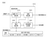
- An example of an internal configuration of change judgment part 510 is shown roughly.
- An example of the method of controlling the operation of the lawn mower 210 will be schematically shown.
- An example of a mode when the lawnmower 210 approachs a boundary is shown roughly.
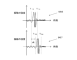
- An example of the vibration data when the lawn mower 210 enters the boundary is schematically shown.
- An example of the internal configuration of the management server 230 is schematically shown.
- An example of the internal configuration of the map management unit 1030 is schematically shown.
- An example of a setting screen 1200 is shown roughly.
- FIG. 1 schematically shows an example of the internal configuration of the work machine 150.
- FIG. 1 schematically shows an example of the internal configuration of the control device 180.
- the work machine 150 includes, for example, a vibration detection unit 160 and a control device 180.
- the work machine 150 may include a plurality of vibration detection units 160.
- the control device 180 includes, for example, a vibration information acquisition unit 182 and at least one of a boundary detection unit 184 and a control unit 186.
- details of the work machine 150 will be described by taking as an example the case where the work machine 150 detects the boundary 106 between the work area 102 and the non-work area 104. Further, the details of the work machine 150 will be described by taking as an example the case where the work machine 150 changes at least one of the traveling direction, the traveling speed, the travel mode, and the work mode in the vicinity of the boundary 106 between the work area 102 and the non-work area 104. Will be described. However, it should be noted that the work machine 150 is not limited to the present embodiment.
- the work area 102 is an area in which the work machine 150 performs a specific work.
- the work area 102 may be an area in which execution of a specific work by the work machine 150 is permitted.
- the non-work area 104 is an area in which the work machine 150 does not perform a specific work.
- the non-work area 104 may be an area in which specific work by the work machine 150 is prohibited.
- a plant 10 that is a target of work grows in the work area 102.
- the plant 10 to be worked does not grow in the non-work area 104.
- the surface state of the work area 102 and the surface state of the non-work area 104 are different. Therefore, the vibration state of the work machine 150 differs between when the work machine 150 is traveling in the work area 102 and when the work machine 150 is traveling in the non-work area 104.
- the boundary 106 separates the inside and the outside of a specific area.
- the boundary 106 divides the inside and outside of the work area 102.
- the non-work area 104 may be an example of an area outside the work area 102.
- a boundary identification member 18 for assisting the detection or identification of the boundary 106 by the work machine 150 is disposed at the boundary 106 between the work area 102 and the non-work area 104.
- the work machine 150 can distinguish between the inside and the outside of the work area 102 by detecting the boundary identification member 18.
- the work machine 150 may distinguish the work area 102, the non-work area 104, and the boundary 106.
- the work machine 150 can distinguish the type of the boundary 106.
- the work machine 150 (i) identifies the type of the boundary 106 and (ii) determines the operation at the boundary 106 based on the type of the boundary 106.
- the boundary identification member 18 is disposed on the boundary 106 and maintains the surface state of the boundary 106 in a state different from the surface state of the work area 102.
- the boundary identification member 18 may maintain the surface state of the boundary 106 in a state different from the surface states of the work area 102 and the non-work area 104.
- the boundary identification member 18 may be made of a material whose surface state is different from the surface state of the work area 102. Examples of the surface state include surface hardness, ease of vibration transmission, and surface roughness.
- various paving materials are used as the boundary identification member 18.
- pavement materials include soil, mud, sand, gravel, pebbles, bricks, concrete, asphalt, blocks, plates, coating films, pellets, particulates, gels and the like.
- the material of the block, the plate, the coating film, the pellet-like substance, and the granular substance may be a resin material, wood, stone, or metal material. Concavities and convexities having specific shapes may be artificially formed on the surfaces of the bricks, blocks, and plates.
- a plant, moss, fungus, slime mold, bacteria, or the like is used as the boundary identification member 18.
- a liquid may be sprayed on the boundary 106 as the boundary identification member 18.
- the boundary identification member 18 is installed so that at least a part thereof is located on the surface of the ground. Thereby, compared with the case where the whole boundary identification member 18 is embed
- the work machine 150 has an autonomous traveling function.
- the work machine 150 may control the movement of the work machine 150 according to the state of the surrounding environment of the work machine 150. For example, the work machine 150 determines whether or not to continue straight ahead, whether to change the direction of travel, whether to stop and turn around, or to change the traveling speed according to the state of the surrounding environment of the work machine 150. Decide whether or not to change.
- the work machine 150 may have a self-position estimation function.
- the work machine 150 may determine a route with reference to the map information.
- the work machine 150 autonomously moves inside the work area 102. It may be determined whether or not entry into the non-work area 104 is permitted in the vicinity of the boundary 106 of the work area 102. For example, when the boundary 106 between the work area 102 and the non-work area 104 is detected, the work machine 150 determines whether or not entry into the non-work area 104 is permitted.
- the work machine 150 may pass through the boundary 106 and enter the non-work area 104.
- the work machine 150 turns around the boundary 106, for example, and moves to the work area 102. Resumes progress toward the inside of.
- the work machine 150 turns around the boundary 106 and proceeds along the boundary 106. You may resume.
- the work machine 150 performs a specific work within the work area 102.
- the work machine 150 stops or interrupts the above work in the non-work area 104.
- the work machine 150 performs a predetermined work while autonomously moving inside the work area 102.
- the work machine 150 may control the work of the work machine 150 according to the state of the surrounding environment of the work machine 150. For example, the work machine 150 determines a work start, work interruption, work stop, work type, work intensity, and the like according to the state of the surrounding environment of the work machine 150.
- the type of work performed by the work machine 150 is not particularly limited.
- the types of work include (i) civil engineering work, (ii) construction work, (iii) cultivation work of plants or agricultural products, (iv) snow removal work, (v) cleaning work, (vi) transporting work, (vii) monitoring Security or security work is exemplified.
- Examples of the cultivation work include sowing seeds, pruning, lawn mowing, mowing, water supply, fertilizing, putting in soil, and weeding.
- the operation of the work machine 150 is controlled based on the vibration state of the work machine 150.
- the vibration state of the work machine 150 changes according to the state of the surface of the ground in contact with the work machine 150. Since the state of the surface of the ground changes in the vicinity of the boundary 106, according to the present embodiment, the operation of the work implement 150 in the vicinity of the boundary 106 can be controlled with a simple configuration. Details of the method for controlling the operation of the work machine 150 will be described later.
- the vibration detection unit 160 is disposed in the work machine 150 and detects the vibration of the work machine 150.
- the vibration detection unit 160 may detect the vibration of the vehicle body of the work machine 150.
- the vibration detection unit 160 may detect the vibration of the wheel of the work machine 150 or the endless track.
- the vibration detection unit 160 is disposed, for example, on at least one of (i) a vehicle body, (ii) a wheel or an endless track, (iii) an axle, and (iv) a suspension device.
- At least one vibration detection unit 160 is arranged at a position ahead of the center of gravity or center of the work implement 150.
- the distance between the vibration detection unit 160 and the outer edge portion of the work implement 150 is greater than the distance between the vibration detection unit 160 and the center of gravity or the center of the work implement 150.
- the distance between the vibration detection unit 160 and the wheel or endless track of the work implement 150 is greater than the distance between the vibration detection unit 160 and the center of gravity or the center of the work implement 150.
- at least two vibration detectors 160 are disposed at positions symmetrical with respect to a central axis that extends in the front-rear direction of the vehicle body through the center of the vehicle body of work implement 150.
- the vibration detection unit 160 a gyro sensor, an acceleration sensor, a combination thereof, and the like are exemplified.
- the gyro sensor may be a uniaxial gyro sensor, a biaxial gyro sensor, or a triaxial gyro sensor.
- the gyro sensor has an angular velocity associated with at least one of a roll axis (an axis extending in the longitudinal direction of the vehicle body), a pitch axis (an axis extending in the horizontal direction of the vehicle body), and a yaw axis (an axis extending in the vertical direction of the vehicle body) It is preferable to output at least one of the angular accelerations.
- the gyro sensor may output a vertical component of at least one of the angular velocity and the angular acceleration of the work machine 150.
- the acceleration sensor may be a uniaxial acceleration sensor, a biaxial acceleration sensor, or a triaxial acceleration sensor.
- the acceleration sensor may output a vertical component of the acceleration of the work machine 150.
- control device 180 controls the work machine 150. More specifically, the control device 180 controls the operation of the work machine 150. Examples of the operation of the work machine 150 include an operation related to the movement of the work machine 150, an operation related to the work of the work machine 150, and the like.
- the control device 180 has at least one of a traveling direction, a traveling speed, a traveling mode, and a working mode of the work implement 150 based on information (sometimes referred to as vibration data) related to vibration detected by the vibration detecting unit 160. Control one. In other embodiments, the controller 180 detects the boundary 106 based on vibration data. The control device 180 may control at least one of the traveling direction, traveling speed, traveling mode, and working mode of the work implement 150 when the boundary 106 is detected.
- the work machine 150 may detect the boundary 106 based on data output from at least one of an inner world sensor and an outer world sensor mounted on the work machine 150. For example, the work machine 150 (i) estimates the position of the work machine 150 and (ii) detects the boundary 106 based on map information including position information of the boundary 106. The work machine 150 may estimate the self-position based on data output from at least one of an internal sensor and an external sensor mounted on the work machine 150. The work machine 150 detects the boundary 106 based on the vibration data output from the vibration detection unit 160 and data output from at least one of the other internal and external sensors mounted on the work machine 150. May be.
- the travel mode defines at least one of (i) a travel pattern and (ii) a travel route interval.
- As the travel pattern (i) position coordinates of a plurality of points on the route are determined in advance, a pattern traveling on the route, and (ii) the shape and size of the route are defined by a predetermined function.
- a pattern that travels on the route (iii) a pattern that travels along the boundary of the work area, (iv) a pattern that travels on a path that has a shape similar to the boundary shape of the work area, and (v) the work area A pattern that travels on a path having a spiral shape from the boundary side to the center side (the shape of the vortex is not particularly limited), (vi) a path having a spiral shape from the center side of the work area toward the boundary side A pattern that travels above (the shape of the vortex is not particularly limited), (vii) a pattern that travels on a path having a zigzag shape, and (viii) a path that has a rectangular wave shape (Ix) a pattern in which the vehicle travels in a direction determined based on an arbitrary probability model (for example, a direction determined randomly) after reaching an arbitrary boundary, x)
- the pattern etc. which drive
- the work mode defines at least one of (i) whether or not work can be performed and (ii) work intensity.
- As the work mode (i) a mode in which work is performed while moving, (ii) a mode in which work is stopped or interrupted during movement, (iii) work is performed during straight travel, but work is stopped during turning operations. Or the mode etc. which are interrupted are illustrated.
- Other examples of the work mode include (i) a mode having a relatively high work intensity, (ii) a mode having a medium work intensity, and (iii) a mode having a relatively low work intensity.
- strength may be represented by the continuous numerical value and may be represented by the step-wise division
- the work mode include (iv) a mode for returning to the home station and (v) a mode for moving from the home station to the work start position of the target work.
- the home station may be a standby place or a storage place for the work machine 150.
- the home station may be provided with a replenishing device for replenishing the work machine 150 with energy or consumables.
- the home station may be arranged inside the work area of the work machine 150 or may be arranged outside the work area.
- the vibration information acquisition unit 182 acquires vibration data from the vibration detection unit 160.
- the vibration data may be information in which information indicating the time is associated with information indicating the magnitude of vibration at the time.
- the vibration information acquisition unit 182 may acquire vibration data output from each of the plurality of vibration detection units 160.
- the vibration information acquisition unit 182 may transmit the above vibration data to the boundary detection unit 184.
- the vibration information acquisition unit 182 may transmit the above vibration data to the control unit 186.
- the boundary detection unit 184 detects the boundary 106 between the work area 102 and the non-work area 104 based on the vibration data acquired by the vibration information acquisition unit 182.
- the boundary detection unit 184 may receive the vibration data output from the one or more vibration detection units 160 and output information indicating whether the boundary 106 is detected.
- the information indicating whether or not the boundary 106 is detected may be information indicating that the boundary 106 is detected.
- the boundary detection unit 184 may receive the vibration data output from the one or more vibration detection units 160 and output information indicating the type of the boundary 106.
- the boundary detection unit 184 may output information indicating the operation of the work machine 150 corresponding to the type of the boundary 106.
- the boundary detection unit 184 receives the vibration data output from the one or more vibration detection units 160, changes the direction of travel while continuing the progress, information indicating whether or not the travel may be continued.
- Information indicating that the traveling is interrupted and turning, information indicating that the vehicle moves along the boundary 106, information indicating that the traveling speed is changed, information indicating that the traveling mode is changed, and work mode.
- the control unit 186 controls at least one of the traveling direction, traveling speed, traveling mode, and working mode of the work implement 150 based on the vibration data acquired by the vibration information acquiring unit 182.
- the control unit 186 receives the vibration data output from the one or more vibration detection units 160, and outputs a command for changing at least one of the traveling direction, traveling speed, working mode, and traveling mode of the work implement 150. It's okay.
- the control unit 186 receives the vibration data output from the one or more vibration detection units 160 and indicates whether or not to continue traveling, and indicates that the traveling direction is changed while continuing the traveling.
- Information information indicating that the traveling is interrupted and turned, information indicating that the vehicle moves along the boundary 106, information indicating that the traveling speed is changed, information indicating that the traveling mode is changed, and change of the work mode Outputs information indicating what to do.
- the control unit 186 includes at least one of a traveling direction, a traveling speed, a traveling mode, and a working mode of the work implement 150 based on the data output by the boundary detecting unit 184 based on the vibration data acquired by the vibration information acquiring unit 182. May be controlled.
- the control unit 186 outputs a command for changing at least one of the traveling direction, traveling speed, traveling mode, and working mode of the work implement 150 when the boundary detecting unit 184 detects the boundary 106.
- the control unit 186 has at least one of the traveling direction, traveling speed, traveling mode, and working mode of the work implement 150 based on information indicating the type of the boundary 106 included in the output data of the boundary detecting unit 184.
- control unit 186 determines the traveling direction, traveling speed, traveling mode, and working mode of the work machine 150 based on information indicating the operation of the work machine 150 included in the output data of the boundary detection unit 184. Output an instruction to change at least one.
- the control device 180 controls at least one of the traveling direction, the traveling speed, the traveling mode, and the working mode of the working machine 150 based on the information related to the vibration of the working machine 150. Further, the control device 180 detects the boundary 106 based on the vibration data. Thereby, the control device 180 can control the operation of the work machine 150 in the vicinity of the boundary 106.
- a conductive wire that generates an artificial magnetic field is embedded in the boundary, or detailed map information indicating the boundary of the work area has been created. It is.
- a part of the wire is cut, there is a problem that no current flows through the wire and the work machine cannot recognize the boundary at all.
- the self-position estimation accuracy in the vicinity of the boundary of the work region is lowered.
- the self-position estimation accuracy decreases, there is a problem that it becomes difficult to detect a boundary using map information indicating the boundary of the work area. In the first place, creating the map information indicating the boundaries of the work area itself requires a lot of labor.
- the control device 180 detects the boundary 106 or detects the boundary 106. It is possible to control the operation of the work machine 150 in the vicinity. Further, even when the boundary identification member 18 is not disposed on the boundary 106, the control device 180 may detect the boundary 106 or control the operation of the work machine 150 in the vicinity of the boundary 106. Can do.
- control device 180 can detect the boundary 106 and control the operation of the work machine 150 in the vicinity of the boundary 106. .
- the control device 180 detects the boundary 106 based on the information indicating the estimated position of the work machine 150 and the information indicating the vibration state of the work machine 150, and the operation of the work machine 150 in the vicinity of the boundary 106. Or may be controlled.
- the boundary identification member 18 is disposed on the boundary 106, and the control device 180 detects the boundary identification member 18 to detect the boundary 106, or a work machine in the vicinity of the boundary 106.
- the details of the control device 180 have been described by taking as an example an embodiment that controls 150 operations.
- the control device 180 is not limited to this embodiment.
- the boundary identification member 18 is not disposed between the work area 102 and the non-work area 104, and the work area 102 and the non-work area 104 may be adjacent to each other.
- the control device 180 detects the boundary 106 based on the difference between (i) the surface state of the work area 102 and (ii) the surface state of the non-work area 104. It is possible to control the operation of the work machine 150 in the vicinity of 106.
- the control device 180 includes (i) a vibration pattern detected by the vibration detection unit 160 when the work machine 150 is traveling in the work area 102, and (ii) the work machine 150 travels in the non-work area 104.
- the boundary 106 can be detected or the operation of the work implement 150 in the vicinity of the boundary 106 can be controlled based on the difference from the vibration pattern of the vibration detected by the vibration detection unit 160 during the operation.
- control device 180 may be an information processing device that can send and receive information to and from work machine 150 via a communication network, and may be realized by the information processing device.
- Each unit of the work machine 150 may be realized by hardware, may be realized by software, or may be realized by hardware and software.
- the constituent elements realized by the software are information processing apparatuses having a general configuration. In the above, it may be realized by starting a program that defines an operation related to the component.
- the information processing apparatus includes (i) a data processing apparatus having a processor such as a CPU and GPU, ROM, RAM, a communication interface, and (ii) a keyboard, a touch panel, a camera, a microphone, various sensors, a GPS receiver, and the like.
- An input device (iii) an output device such as a display device, a speaker, and a vibration device, and (iv) a storage device (including an external storage device) such as a memory and an HDD may be provided.
- the data processing apparatus or the storage device may store the program.
- the above program is executed by a processor to cause the information processing apparatus to execute an operation defined by the program.
- the above program may be stored in a non-transitory computer-readable recording medium.
- the above program may be a program for causing a computer to function as the control device 180.
- the computer described above may be a computer that provides a cloud service or a computer that implements a client-server system.
- the computer may be (i) a computer mounted on the work machine 150, or (ii) a computer external to the work machine 150 and controlling the work machine 150 via a communication network. May be.
- the above program may be a program for causing a computer to execute one or a plurality of procedures related to various types of information processing in the control device 180.
- One or more procedures related to various types of information processing in the control device 180 may be procedures for controlling the work machine 150.
- the procedure for controlling the work machine 150 includes, for example, a vibration information acquisition stage for acquiring vibration information related to vibration detected by the vibration detection unit 160 from the vibration detection unit 160 mounted on the work machine 150.
- the above control method includes, for example, a control stage that controls at least one of the traveling direction, traveling speed, traveling mode, and work mode of the work implement 150 based on the vibration information acquired in the vibration information acquisition stage.
- the above control method includes, for example, a boundary detection stage that detects the boundary 106 between the work area 102 and the non-work area 104 of the work machine 150 based on the vibration information acquired in the vibration information acquisition stage.
- FIG. 2 schematically shows an example of the system configuration of the management system 200.
- the management system 200 includes one or more lawn mowers 210 and a management server 230.
- the management system 200 may include one or a plurality of user terminals 22.
- the lawn mower 210 may be an example of a working machine.
- the computer of the lawn mower 210 may be an example of a control device.
- the lawn mower 210 has an autonomous movement function, and a computer mounted on the lawn mower 210 controls the operation of the lawn mower 210 as an example. Details of the management system 200 will be described. However, the management system 200 is not limited to this embodiment. In another embodiment, at least one of the user terminal 22 and the management server 230 may control the operation of the lawn mower 210. In this case, at least one of the user terminal 22 and the management server 230 may be an example of a control device.
- an operation for growing the turf 12 is performed inside the work area 202.
- the grass 12 may be an example of a plant or an agricultural product.
- the position and range of the work area 202 are not particularly limited.
- the area range may represent the size and shape of the area.
- the work area 202 may have any geographic area.
- the work area 202 may have a predetermined geographic area. Examples of the type of work for growing the turf 12 include sowing, pruning, lawn mowing, mowing, water supply, fertilizing, putting in soil, weeding, and the like.
- the lawn mower 210 having an autonomous running function performs lawn mowing while moving inside the work area 202.
- the work area 202 includes a plurality of subareas 204.
- the sub-area 204 may be an area delimited by a physical geographical boundary or an area delimited by a virtual geographical boundary.
- Physical geographical boundaries include (i) boundaries defined by naturally or artificially formed structures, (ii) boundaries defined by dispersed chemicals, (iii) visible light, infrared Examples include boundaries defined by electromagnetic waves such as ultraviolet rays, (iv) boundaries defined by magnetic fields, and (v) boundaries defined by sound waves or ultrasonic waves.
- naturally formed structures include depressions, steps, slopes, lakes, and rivers.
- artificially formed structure include a passage, a groove, a tunnel, a building, a wire, a rope, a fence, a net, and a braille block.
- Examples of the virtual geographical boundary include a geofence and a virtual wire.
- the virtual wire may be a geographical boundary defined by a virtual line set between a plurality of structures.
- the number of sub areas 204 included in the work area 202 and the size and shape of the sub areas 204 are not particularly limited. However, it is preferable that the plurality of sub-areas 204 be uniformly arranged inside the work area 202 so that there is no arrangement omission and overlapping arrangement.
- the sizes of the plurality of sub-areas 204 may be the same or different.
- the shapes of the plurality of sub-areas 204 may be the same or different.
- the number of sub-areas 204 arranged in the work area 202 may be fixed or variable. For example, the number of sub-areas 204 arranged in a specific area constituting a part of the work area 202 is changed with the occurrence of a predetermined event as a trigger. Specifically, a plurality of adjacent subareas 204 may be virtually combined to form a single subarea 204. A single subarea 204 may be virtually divided into a plurality of subareas 204 arranged adjacent to each other. The number of sub-areas 204 arranged in a specific area inside the work area 202 may be adjusted according to the required accuracy.
- a tile 208 is arranged at a boundary 206 that divides the inside and outside of the work area 202.
- the outside of the work area 202 may be an example of a non-work area.
- the material of the tile 208 is selected so that the vibration state of the lawn mower 210 is different between when the lawn mower 210 travels on the lawn 12 and when the lawn mower 210 travels on the tile 208.
- An artificial uneven pattern may be formed on the surface of the tile 208.
- the boundary 206 will be described by taking as an example a case where a single boundary 206 is formed along the outer periphery of the work area 202.
- the boundary 206 is not limited to this embodiment.
- the work area 202 may be defined by a plurality of boundaries 206, and one or more boundaries 206 may be formed within the work area 202.
- the work area 202 is defined by a plurality of boundaries 206.
- the work area 202 defines a first edge that defines the outer edge of the work area 202.
- a second boundary 206 that defines the outer edge of the obstacle or the like.
- the vibration pattern that appears when the lawn mower 210 runs on the tile 208 is determined by the material of the tile 208 and the uneven pattern. Therefore, the user of the lawn mower 210 can control the operation of the lawn mower 210 in the vicinity of the boundary 206 by selecting at least one of the material of the tile 208 and the uneven pattern.
- the vibration pattern may be identified by a learned learner or may be identified according to a predetermined analysis procedure.
- the vibration pattern is identified based on at least one of the frequency, amplitude, and phase of the vibration waveform, for example.
- the vibration pattern is identified by the frequency distribution of the vibration waveform.
- the vibration pattern is identified based on the distribution shape of the frequency distribution.
- the vibration pattern may be identified by pattern recognition of the distribution shape of the frequency distribution, or may be identified by whether or not vibrations of one or a plurality of specific frequencies are included.
- the vibration pattern may be identified based on the value of at least one frequency of one or more peaks appearing in the frequency distribution of the vibration waveform.
- the vibration pattern may be identified based on a ratio of spectral intensities of a plurality of peaks.
- the vibration pattern is identified by the appearance pattern of one or more specific frequency vibrations.
- vibrations of a specific frequency may repeatedly appear and disappear.
- the vibration pattern may be identified based on at least one of the frequency, amplitude and phase of the appearance pattern of the vibration at a specific frequency.
- the vibration pattern is identified by the magnitude of the vibration amplitude.
- the vibration pattern is identified by at least one of an average value, a median value, and a mode value of the amplitude of vibration sampled during a predetermined period.
- the threshold for identifying each of the plurality of vibration patterns may be determined according to the traveling speed of the lawn mower 210 at the time of sampling.
- the vibration pattern is identified by a vibration intermittent pattern.
- an intermittent pattern may appear due to the repetition of the time when the amplitude of vibration exceeds a specific threshold and the time when the amplitude of vibration falls below the threshold. is there.
- the vibration pattern may be identified based on at least one of the frequency, amplitude, and phase of the intermittent pattern.
- a single boundary 206 may be formed by a single type of tile 208, or may be formed by a plurality of types of tiles 208. More specifically, the tile 208 arranged at the first point on the boundary 206 and the tile 208 arranged at the second point on the boundary 206 include (i) material and (ii) on the surface of the tile 208. At least one of the formed uneven patterns may be different. The first point and the second point may be geographically separated.
- the single boundary 206 may include a plurality of types of boundaries. Even when the single boundary 206 is formed by a plurality of types of tiles 208, the types of boundaries indicated by the plurality of tiles 208 may be the same.
- the boundary types are (i) a boundary indicating that the lawn mower 210 is prohibited from traveling in the area ahead of the boundary, and (ii) the lawn mower 210 allowed to travel in the area beyond the boundary.
- a boundary indicating that the instruction is being performed, and (iii) a boundary for transmitting a specific command to the lawn mower 210 are exemplified.
- the specific command includes a command for instructing to travel in a specific direction, a command for instructing to travel at a specific speed, and a command to instruct to travel in a specific driving mode.
- An instruction, an instruction for instructing an instruction for instructing start or stop of a specific work, and the like are exemplified.
- the boundary 206 may have the same configuration as the boundary 106 as long as no technical contradiction occurs. Similarly, the boundary 106 may have the same configuration as the boundary 206 as long as no technical contradiction occurs.
- the tile 208 may be an example of the boundary identification member 18. The tile 208 may have the same configuration as the boundary identification member 18 as long as no technical contradiction occurs. Similarly, the boundary identification member 18 may have the same configuration as the tile 208 as long as there is no technical contradiction.
- Each part of the management system 200 may send and receive information to and from each other.
- the lawn mower 210 transmits and receives information to and from at least one of the user terminal 22 and the management server 230 via the communication network 20.
- the communication network 20 may be a wired communication transmission line, a wireless communication transmission line, or a combination of a wireless communication transmission line and a wired communication transmission line.
- the communication network 20 may include a wireless packet communication network, the Internet, a P2P network, a dedicated line, a VPN, a power line communication line, and the like.
- the communication network 20 may include (i) a mobile communication network such as a mobile phone network, (ii) a wireless MAN (for example, WiMAX (registered trademark)), a wireless LAN (for example, WiFi (registered trademark)). Or a wireless communication network such as Bluetooth (registered trademark), Zigbee (registered trademark), NFC (Near Field Communication), or the like.
- the user terminal 22 is a communication terminal used by the user of the management system 200 or the lawn mower 210, and details thereof are not particularly limited.
- Examples of the user terminal 22 include a personal computer and a portable terminal.
- Examples of the portable terminal include a mobile phone, a smartphone, a PDA, a tablet, a notebook computer or a laptop computer, and a wearable computer.
- the management system 200 manages the work area 202.
- the management system 200 may manage the state of an object (sometimes referred to as a work target) that is a target of work performed in the work area 202.
- the grass 12 may be an example of a work target.
- the management system 200 may manage work performed in the work area 202.
- the management system 200 manages a work schedule.
- the work schedule may be information that defines at least one of a work execution time, a work execution place, a work execution subject, a work target, and a work content.
- the management system 200 manages the lawn mower 210.
- the lawn mower 210 may be an example of a work execution entity.
- the management system 200 manages the state of the lawn mower 210.
- the management system 200 displays the position of the lawn mower 210, the traveling direction, the traveling speed, the travel mode, the work mode, the remaining energy (for example, the remaining battery power), the schedule of work performed by the lawn mower 210, and the like. to manage.
- the lawn mower 210 has an autonomous running function.
- the vehicle travels autonomously inside the work area 202.
- the lawn mower 210 may be moved by a user's remote operation.
- the lawn mower 210 cuts the lawn 12 growing inside the work area 202.
- the lawn mower 210 may travel while cutting the lawn 12 or may travel without cutting the lawn 12. Details of the lawn mower 210 will be described later.
- the lawn mower 210 may be an example of a work machine (sometimes referred to as a work machine).
- the working machine is not limited to the lawn mower 210.
- the working machine may be a moving body traveling on land, a moving body flying in the air, or a moving body navigating in water or on water.
- Other examples of the work machine include a drone, a helicopter, an airship, and the like flying in the air.
- the work machine described above may have an autonomous movement function. When the work machine is controlled based on the vibration information of the work machine, the work machine is preferably a moving body that travels on land.
- the management server 230 manages various types of information regarding the work area 202.
- the management server 230 manages geographical information about the work area 202 (sometimes referred to as map information).
- the management server 230 manages information indicating the position of the boundary 206 with respect to the work area 202.
- the management server 230 stores information in which information indicating the position of a specific point or region on the boundary 206 is associated with information indicating the type of boundary at the point or region. to manage.
- information in which information indicating the position of a specific point or region on the boundary 206 is associated with information indicating the content of the operation of the lawn mower 210 at the point or region is managed.
- the management server 230 may manage the state of the devices constituting the management system 200.
- the management server 230 may control the operation of the devices that make up the management system 200.
- the management server 230 may manage the growth state of the turf 12.
- the management server 230 may manage various operations performed in the work area 202. For example, the management server 230 creates schedules for the various operations described above.
- the management server 230 may manage the progress of the various work schedules. Details of the management server 230 will be described later.
- Each unit of the management system 200 may be realized by hardware, may be realized by software, or may be realized by hardware and software. At least a part of each part of the management system 200 may be realized by a single server or a plurality of servers. At least a part of each part of the management system 200 may be realized on a virtual server or a cloud system. At least a part of each part of the management system 200 may be realized by a personal computer or a portable terminal. Examples of the portable terminal include a mobile phone, a smartphone, a PDA, a tablet, a notebook computer or a laptop computer, and a wearable computer.
- the management system 200 may store information using a distributed ledger technology such as a block chain or a distributed network.
- the constituent elements realized by the software define operations related to the constituent elements in an information processing apparatus having a general configuration. It may be realized by starting a program.
- the information processing apparatus includes (i) a data processing apparatus having a processor such as a CPU and GPU, ROM, RAM, a communication interface, and (ii) a keyboard, a touch panel, a camera, a microphone, various sensors, a GPS receiver, and the like.
- An input device, (iii) an output device such as a display device, a speaker, and a vibration device, and (iv) a storage device (including an external storage device) such as a memory and an HDD may be provided.
- the data processing apparatus or the storage device may store the program.
- the above program is executed by a processor to cause the information processing apparatus to execute an operation defined by the program.
- the above program may be stored in a non-transitory computer-readable recording medium.
- the above program may be a program for causing a computer to execute one or a plurality of procedures related to various types of information processing in the management system 200.
- the above program may be a program for causing a computer to function as a control device that controls the lawn mower 210.
- the one or more procedures related to various types of information processing in the management system 200 may be procedures for controlling the lawn mower 210.
- the procedure for controlling the lawn mower 210 includes, for example, a vibration information acquisition step of acquiring vibration information related to vibration detected by the vibration detection unit from a vibration detection unit mounted on the lawn mower 210.
- the above control method includes a control step of controlling at least one of the traveling direction, traveling speed, traveling mode, and work mode of the lawn mower 210 based on the vibration information acquired in the vibration information acquisition step, for example.
- the above control method includes, for example, a boundary detection stage that detects the boundary 206 based on the vibration information acquired in the vibration information acquisition stage.
- the computer may be a computer mounted on at least one of the user terminal 22, the lawn mower 210, and the management server 230.
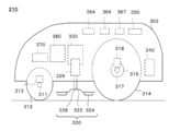
- FIG. 3 schematically shows an example of the internal configuration of the lawn mower 210.
- the lawn mower 210 includes a housing 302.
- the lawn mower 210 includes a pair of front wheels 312 and a pair of rear wheels 314 at the bottom of the housing 302.
- the lawn mower 210 may include a pair of traveling motors 316 that drive each of the pair of rear wheels 314.
- the front wheel 312 is connected to the axle 311.
- the axle 311 is connected to the housing 302 via the suspension device 313.
- the rear wheel 314 is connected to the axle 317.
- the axle 317 is connected to the housing 302 via the suspension device 318.
- the suspension apparatus 318 may be an axle suspension type suspension system (sometimes referred to as a rigid axle) or an independent suspension system suspension system.
- the lawn mower 210 includes a work unit 320.
- the work unit 320 includes, for example, a blade disk 322, a cutter blade 324, a work motor 326, and a shaft 328.
- the lawn mower 210 may include a position adjustment unit 330 that adjusts the position of the work unit 320.
- the blade disk 322 is connected to the work motor 326 via the shaft 328.
- the cutter blade 324 may be a cutting blade for cutting turf.
- the cutter blade 324 is attached to the blade disk 322 and rotates with the blade disk 322.
- the work motor 326 rotates the blade disk 322.
- the blade disk 322 and the cutter blade 324 may be an example of a cutting member for cutting a work target.
- the lawn mower 210 includes a battery unit 340, a user interface 350, an imaging unit 364, a vibration sensor 366, a vibration sensor 367, and a sensor unit inside or on the housing 302. 370 and a control unit 380.
- the imaging unit 364 may be an example of an imaging unit.
- the vibration sensor 366 and the vibration sensor 367 may be an example of a vibration detection unit.
- the vibration sensor 366 may be an example of one of a first vibration detection unit and a second vibration detection unit.
- the vibration sensor 367 may be an example of the other of the first vibration detection unit and the second vibration detection unit.
- the control unit 380 may be an example of a control device.
- the control unit 380 may have the same configuration as the control device 180 within a technically consistent range. Similarly, the control device 180 may have the same configuration as the control unit 380 within a technically consistent range.
- the battery unit 340 supplies power to each part of the lawn mower 210.
- the user interface 350 accepts user input.
- the user interface 350 outputs information to the user. Examples of the user interface 350 include a keyboard, a pointing device, a microphone, a touch panel, a display, and a speaker.
- the imaging unit 364 images the surroundings of the lawn mower 210.
- the imaging unit 364 may image at least a part of the work area 202.
- the imaging unit 364 may transmit captured image data to the management server 230.
- the image may be a moving image or a still image.
- the image may be a wide-angle image, a 180-degree panoramic image, or a 360-degree panoramic image.
- the image may be an image captured by a visible light camera or an image captured by an infrared camera.
- the image data may be information in which captured image data is associated with information indicating a position where the image is captured.
- the image data may be information in which captured image data is associated with information indicating the time when the image was captured.
- the information indicating the position where the image is captured may be an example of information for associating the position where the vibration is detected with the position where the image is captured.
- the information indicating the time when the image is captured may be an example of information for associating the position where the vibration is detected with the position where the image is captured.
- the imaging unit 364 obtains image data of an image captured in a period including a time when the vibration is detected. May be transmitted to the management server 230. For example, the imaging unit 364 transmits image data of an image captured during 30 seconds before and after the time when vibration is detected to the management server management server 230.
- the length of the period is not particularly limited, but the period preferably includes a period from one minute before the time when the vibration is detected to the time when the vibration is detected, and the vibration is detected. It is more preferable to include a period from 30 seconds before the time when the vibration is detected, and it is further preferable to include a period from 30 seconds before the time when the vibration is detected to the time when the vibration is detected.
- the period preferably includes a period from the time when the vibration is detected to one minute after the time when the vibration is detected, and the period from the time when the vibration is detected to 30 seconds after the time when the vibration is detected Is more preferable, and it is further preferable that a period from the time when the vibration is detected to 15 seconds after the time when the vibration is detected is included.
- the imaging unit 364 may transmit information indicating at least one of the imaging direction and the imaging condition to the management server 230.
- imaging conditions include zoom magnification, aperture, presence / absence of optical filter, optical filter type, resolution, shutter speed, frame rate, ISO sensitivity, shooting altitude, angle of view, focal length, rendering settings, etc.
- the imaging unit 364 may execute various processes based on the control signal from the control unit 380. Examples of the processing include start of imaging, stop of imaging, adjustment or change of imaging direction, adjustment or change of imaging conditions, storage of image data, transmission of image data, and the like.
- the vibration sensor 366 and the vibration sensor 367 detect the vibration of the lawn mower 210.
- the vibration sensor 366 and the vibration sensor 367 output information related to the detected vibration (sometimes referred to as vibration data).
- the vibration sensor 366 and the vibration sensor 367 transmit vibration data to the management server 230.
- the vibration data may be data in which information indicating time is associated with information indicating the magnitude of vibration at the time.
- the vibration sensor 366 and the vibration sensor 367 may have the same configuration as that of the vibration detection unit 160 as long as no technical contradiction occurs. Similarly, the vibration detection unit 160 may have the same configuration as that of at least one of the vibration sensor 366 and the vibration sensor 367 as long as there is no technical contradiction.
- the vibration sensor 366 and the vibration sensor 367 may be arranged at a position suitable for detecting vibration that is a main detection target of the sensor. At least one of the vibration sensor 366 and the vibration sensor 367 may mainly detect vibration of the housing 302. At least one of the vibration sensor 366 and the vibration sensor 367 may mainly detect the vibration of the front wheel 312 or the rear wheel 314. For example, the vibration sensor 366 mainly detects the vibration of the right front wheel 312, and the vibration sensor 367 mainly detects the vibration of the left front wheel 312. The vibration sensor 366 may mainly detect the vibration of the right rear wheel 314, and the vibration sensor 367 may mainly detect the vibration of the left rear wheel 314.
- At least one of the vibration sensor 366 and the vibration sensor 367 includes (i) a housing 302, (ii) a front wheel 312 or a rear wheel 314, (iii) an axle 311 or an axle 317, and (iv) a suspension device 313 or a suspension. Located in at least one of the devices 318. At least one of the vibration sensor 366 and the vibration sensor 367 may be disposed on at least one of (i) the front wheel 312 or the rear wheel 314 and (ii) the axle 311 or the axle 317. Thereby, at least one of the vibration sensor 366 and the vibration sensor 367 can more accurately acquire the vibration generated by the contact between the front wheel 312 or the rear wheel 314 and the ground.
- vibration sensor 366 and the vibration sensor 367 are examples of a plurality of vibration sensors, and the arrangement method of the plurality of vibration sensors is not limited to the present embodiment.
- At least one vibration sensor may be disposed on the right side of the center of gravity of the housing 302, and at least one vibration sensor may be disposed on the left side of the center of gravity of the housing 302. At least one vibration sensor is disposed in the vicinity of the center of gravity of the housing 302, at least one vibration sensor is disposed on the right side of the center of gravity of the housing 302, and at least one vibration sensor is disposed on the left side of the center of gravity of the housing 302. Also good.
- At least one vibration sensor may be disposed on the front side of the center of gravity of the housing 302, and at least one vibration sensor may be disposed on the rear side of the center of gravity of the housing 302. At least one vibration sensor is disposed near the center of gravity of the housing 302, at least one vibration sensor is disposed on the front side of the center of gravity of the housing 302, and at least one vibration sensor is disposed on the rear side of the center of gravity of the housing 302. May be.
- At least one vibration sensor may be disposed above the center of gravity of the housing 302, and at least one vibration sensor may be disposed below the center of gravity of the housing 302. At least one vibration sensor is disposed in the vicinity of the center of gravity of the housing 302, at least one vibration sensor is disposed above the center of gravity of the housing 302, and at least one vibration sensor is disposed below the center of gravity of the housing 302. May be.
- the installation positions of a plurality of vibration sensors may be determined by a combination of the above three arrangement methods.
- the member on which the vibration sensor is arranged is not particularly limited.
- the vibration sensor may be arranged in the housing 302, the front wheel 312, the rear wheel 314, the axle 311, the axle 317, the suspension device 313, the suspension device 318, and the like.
- the sensor unit 370 includes various sensors.
- the sensor unit 370 may include various internal sensors.
- the sensor unit 370 may include various external sensors.
- the sensor unit 370 may transmit the outputs of various sensors to the control unit 380. Examples of sensors include millimeter wave sensors, proximity detection sensors, wheel speed sensors, load sensors, idling detection sensors, magnetic sensors, geomagnetic sensors (sometimes called orientation sensors, electronic compass, etc.), soil moisture sensors, and the like. Is done.
- the wheel speed sensor may be a rotary encoder that detects the rotation angle or the rotation speed of the wheel.
- the sensor unit 370 may include a sensor that detects a change in the position of the axle 311 or the axle 317, a sensor that detects an acceleration near the center of gravity of the lawn mower 210, a sensor that detects an angular velocity near the center of gravity of the lawn mower 210, and the like.
- control unit 380 controls the operation of the lawn mower 210. According to one embodiment, the control unit 380 controls the movement of the lawn mower 210 by controlling the pair of travel motors 316. According to another embodiment, the control unit 380 controls the work motor 326 to control the work of the lawn mower 210.
- the control unit 380 may control the operation of the lawn mower 210 based on at least one output of the imaging unit 364, the vibration sensor 366, the vibration sensor 376, and the sensor unit 370.
- the control unit 380 may control the operation of the lawn mower 210 based on an instruction from the management server 230.
- the lawn mower 210 may be controlled based on information indicating the work schedule generated by the management server 230.
- the control unit 380 may control the lawn mower 210 according to the command generated by the management server 230. Details of the control unit 380 will be described later.
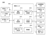
- FIG. 4 schematically shows an example of the internal configuration of the control unit 380.
- the control unit 380 includes a communication control unit 410, a travel control unit 420, a work unit control unit 430, and an input / output control unit 440.
- control unit 380 includes a control parameter determination unit 450.
- the control unit 380 may include a storage unit 460.
- the control parameter determination unit 450 may be an example of a control device.
- the control parameter determination unit 450 may have the same configuration as the control device 180 described with reference to FIG. 1 within a technically consistent range.
- the control device 180 may have the same configuration as the control parameter determination unit 450 within a technically consistent range.
- the communication control unit 410 controls communication with an external device of the lawn mower 210.
- the communication control unit 410 may be a communication interface corresponding to one or a plurality of communication methods. Examples of external devices include the user terminal 22 and the management server 230.
- the traveling control unit 420 controls the traveling motor 316 to control the movement of the lawn mower 210.
- the traveling control unit 420 controls autonomous traveling of the lawn mower 210.
- the traveling control unit 420 controls at least one of the traveling speed, traveling direction, traveling mode, and traveling route of the lawn mower 210.
- the traveling control unit 420 may execute at least one of straight-ahead control, rotation control, and circulation control of the lawn mower 210 using the data output from the sensor unit 370.
- the traveling control unit 420 may monitor the current value of the traveling motor 316.
- the work unit control unit 430 controls the work unit 320.
- the work unit control unit 430 may control at least one of the work mode, the work type, the work intensity, and the work execution timing of the work unit 320.
- the work unit control unit 430 controls the work motor 326 to control the work intensity of the work unit 320.
- the work unit control unit 430 may control the position adjustment unit 330 to control the work intensity of the work unit 320.
- the work unit control unit 430 may monitor the current value of the work motor 326.
- the input / output control unit 440 receives an input from at least one of the user interface 350, the imaging unit 364, the vibration sensor 366, the vibration sensor 367, and the sensor unit 370.
- the input / output control unit 440 may control at least one of the user interface 350, the imaging unit 364, the vibration sensor 366, the vibration sensor 367, and the sensor unit 370.
- the input / output control unit 440 outputs information to the user interface 350.
- the input / output control unit 440 may output information to at least one of the user terminal 22 and the management server 230 via the communication control unit 410.
- the input / output control unit 440 indicates the state of the lawn mower 210 when the estimation accuracy of the self-position of the lawn mower 210 does not satisfy a predetermined reference or when some abnormality occurs in the lawn mower 210.
- Information is output to at least one of the user terminal 22 and the management server 230.
- control parameter determination unit 450 determines a parameter (sometimes referred to as a control parameter) for controlling at least one of the travel control unit 420 and the work unit control unit 430.
- the control parameter determination unit 450 controls at least one of the traveling direction, traveling speed, traveling mode, and working mode of the lawn mower 210 based on the vibration data output by at least one of the vibration sensor 366 and the vibration sensor 367.
- control parameter determination unit 450 receives (i) vibration data output from at least one of the vibration sensor 366 and the vibration sensor 367, and (ii) outputs a control parameter.
- the control parameter determination unit 450 may generate a control parameter for controlling at least one of the traveling direction, traveling speed, work mode, and traveling mode of the lawn mower 210 based on the input vibration data.
- the control parameter determination unit 450 may determine whether or not to change the control parameter.
- the control parameter determination unit 450 is, for example, the control parameter determination unit 450 receives (i) vibration data output from at least one of the vibration sensor 366 and the vibration sensor 367, and (ii) whether to change the control parameter. Outputs information indicating that. Details of the control parameter determination unit 450 will be described later.
- the storage unit 460 stores various types of information.
- the storage unit 460 may store various types of information used by the control parameter determination unit 450 to generate control parameters.
- the storage unit 460 may store geographical information regarding the work area 202. In other embodiments, the storage unit 460 may store setting information for determining the operation of the lawn mower 210. Examples of the setting information include setting information regarding the operation of the lawn mower 210 when a change in vibration pattern is detected, setting information regarding the operation of the lawn mower 210 when a specific vibration pattern is detected, and the like. The setting information may be an example of control information.
- FIG. 5 schematically shows an example of the internal configuration of the control parameter determination unit 450.
- the control parameter determination unit 450 includes a change determination unit 510 and a parameter determination unit 520.
- the parameter determination unit 520 includes a traveling direction determination unit 522, a traveling speed determination unit 524, a travel mode determination unit 526, and a work mode determination unit 528.
- the change determination unit 510 may be an example of a control device, a vibration information acquisition unit, a control unit, and a change determination unit.
- the parameter determination unit 520 may be an example of a control unit.
- the traveling direction determination unit 522 may be an example of a command output unit.
- the change determination unit 510 determines whether or not the control parameter needs to be changed based on vibration data output by at least one of the vibration sensor 366 and the vibration sensor 367.
- the change determination unit 510 may determine a control parameter to be changed among a plurality of types of control parameters. Accordingly, the change determination unit 510 controls at least one of the traveling direction, traveling speed, work mode, and traveling mode of the lawn mower 210 based on the vibration data output by at least one of the vibration sensor 366 and the vibration sensor 367. be able to.
- the change determination unit 510 may determine whether or not a control parameter needs to be changed based on vibration data output by at least one of the vibration sensor 366 and the vibration sensor 367. In another embodiment, the change determination unit 510 may determine whether or not the control parameter needs to be changed when the boundary 206 of the work area 202 is detected. The change determination unit 510 may determine whether or not the control parameter needs to be changed when the boundary 206 of the work area 202 is detected based on the vibration data.
- the boundary 206 of the work area 202 includes (i) a boundary for distinguishing between the inside and the outside of the work area 202, and (ii) a boundary for distinguishing an outer edge such as an obstacle arranged in the work area 202. Etc. are exemplified. Details of the change determination unit 510 will be described later.
- the parameter determination unit 520 determines the contents of various control parameters. For example, when the change determination unit 510 determines that the control parameter needs to be changed, the parameter determination unit 520 determines the content of the control parameter. The parameter determination unit 520 may determine the content of the control parameter determined as the control parameter to be changed by the change determination unit 510 among the plurality of types of control parameters.
- the traveling direction determination unit 522 determines a control parameter for controlling the traveling direction of the lawn mower 210. For example, the traveling direction determination unit 522 determines the control parameter described above when the change determination unit 510 determines that the traveling direction of the lawn mower 210 should be changed. The traveling direction determination unit 522 may output a control parameter indicating the traveling direction after the change. The control parameter output by the traveling direction determination unit 522 is transmitted to the traveling control unit 420, for example. Accordingly, the traveling direction determination unit 522 can control the traveling direction of the lawn mower 210.
- the control parameter may be an example of a command for changing the traveling direction of the lawn mower 210.
- the traveling direction determination unit 522 may determine an angle formed by the traveling direction before the change and the traveling direction after the change using a probability model. “An angle between the direction of travel before the change and the direction of travel after the change” is calculated when the start point of the plane vector that indicates the direction of travel before the change and the start point of the plane vector that indicates the direction of travel after the change overlap. Of the two angles formed by the two vectors, it may mean an angle that is 180 degrees or less.
- the details of the traveling direction determination unit 522 are exemplified by a case where the traveling direction after the change is determined by determining the angle formed by the traveling direction before the change and the traveling direction after the change. Will be explained.
- the method by which the traveling direction determination unit 522 determines the traveling direction after the change is not limited to the present embodiment.
- the traveling direction determination unit 522 may determine the traveling direction after the change by determining (i) the amount of rotation (for example, the rotation angle) of the lawn mower 210 at the turning position.
- You may determine the advancing direction after a change by determining the azimuth
- the traveling direction determination unit 522 randomly determines the changed traveling direction. Thereby, when the change determination unit 510 determines that the traveling direction of the lawn mower 210 should be changed, the traveling direction of the lawn mower 210 is randomly changed. As a result, the frequency with which the lawn mower 210 enters the specific area is adjusted.
- the traveling direction determination unit 522 determines the traveling direction after the change so that the angle formed by the traveling direction before the change and the traveling direction after the change is within a specific numerical range. It's okay.
- the changed traveling direction may be calculated using an arbitrary probability model.
- the advancing direction determining unit 522 has an angle formed by the advancing direction before the change and the advancing direction after the change of 90 degrees or more, preferably more than 90 degrees, more preferably more than 120 degrees, and still more preferably more than 120 degrees.
- the above numerical range is set so that And the advancing direction determination part 522 determines the advancing direction after a change within the range of said numerical range. Thereby, the approach to the area
- the angle formed by the traveling direction before the change and the traveling direction after the change is 90 degrees or less, preferably less than 90 degrees, more preferably 60 degrees or less, and even more preferably less than 60 degrees.
- the above numerical range may be set.
- the advancing direction determination part 522 determines the advancing direction after a change within the range of said numerical range. Thereby, the approach to the area
- the traveling direction determination unit 522 may determine the traveling direction after the change based on the type of the boundary 206. In still another embodiment, the traveling direction determination unit 522 may determine the traveling direction after the change based on the estimated position of the lawn mower 210.
- the travel direction after the change is indicated by, for example, an angle formed by the travel direction before the change and the travel direction after the change.
- the travel direction after the change may be indicated by an angle formed between the extending direction of the adjacent boundary 206 and the travel direction after the change.
- the traveling direction after the change may be indicated by an azimuth or a direction.
- the direction of travel after the change may be indicated by the identification information of the target landmark.
- the traveling direction after the change may be indicated by an angle determined with reference to a specific landmark.
- the traveling speed determination unit 524 determines a control parameter for controlling the traveling speed of the lawn mower 210. For example, the traveling speed determination unit 524 determines the control parameter described above when the change determination unit 510 determines that the traveling direction of the lawn mower 210 should be changed. The traveling speed determination unit 524 may output a control parameter indicating the traveling speed after the change. The control parameter output by the traveling speed determination unit 524 is transmitted to the traveling control unit 420, for example. Thereby, the traveling speed determination unit 524 can control the traveling speed of the lawn mower 210.
- the traveling speed determination unit 524 may determine the traveling speed after the change based on the type of the boundary 206. In another embodiment, the traveling speed determination unit 524 may determine the traveling speed after the change based on the estimated position of the lawn mower 210. In still another embodiment, the traveling speed determination unit 524 may determine the traveling speed after the change based on the time or the time zone.
- the traveling mode determination unit 526 determines a control parameter for controlling the traveling mode of the lawn mower 210. For example, the travel mode determination unit 526 determines the control parameter described above when the change determination unit 510 determines that the travel mode of the lawn mower 210 should be changed. The travel mode determination unit 526 may output a control parameter indicating the travel mode after the change. The control parameter output by the travel mode determination unit 526 is transmitted to the travel control unit 420, for example. Thereby, the traveling mode determination unit 526 can control the traveling mode of the lawn mower 210.
- the travel mode determination unit 526 may determine the travel mode after the change based on the type of the boundary 206. In another embodiment, the travel mode determination unit 526 may determine the changed travel mode based on the estimated position of the lawn mower 210. In still another embodiment, the travel mode determination unit 526 may determine the travel mode after the change based on the time or the time zone.
- the work mode determination unit 528 determines a control parameter for controlling the work mode of the lawn mower 210. For example, the work mode determination unit 528 determines the control parameters described above when the change determination unit 510 determines that the work mode of the lawn mower 210 should be changed. The work mode determination unit 528 may output a control parameter indicating the changed work mode. The control parameter output from the work mode determination unit 528 is transmitted to the work unit control unit 430, for example. Thereby, the work mode determination unit 528 can control the work mode of the lawn mower 210.
- the work mode determination unit 528 may determine the changed work mode based on the type of the boundary 206. In another embodiment, the work mode determination unit 528 may determine the changed work mode based on the estimated position of the lawn mower 210. In still another embodiment, the work mode determination unit 528 may determine the changed work mode based on the time or the time zone.
- FIG. 6 schematically illustrates an example of the internal configuration of the change determination unit 510.
- the change determination unit 510 includes a vibration pattern extraction unit 610, a fluctuation detection unit 620, a setting extraction unit 630, and a determination result generation unit 640.
- the vibration pattern extraction unit 610 may be an example of a vibration information acquisition unit.
- the fluctuation detection unit 620 may be an example of a control unit and a boundary detection unit.
- the setting extraction unit 630 may be an example of an extraction unit.
- the determination result generation unit 640 may be an example of a control unit, a command output unit, and a change determination unit.
- the vibration pattern extraction unit 610 acquires vibration data output by at least one of the vibration sensor 366 and the vibration sensor 367.
- the vibration pattern extraction unit 610 analyzes each of one or a plurality of vibration data, and extracts one or a plurality of vibration patterns included in each vibration data.
- the vibration pattern extraction unit 610 transmits information indicating the extracted vibration pattern to the fluctuation detection unit 620.
- the vibration pattern extraction unit 610 may transmit information indicating the extracted vibration pattern to the setting extraction unit 630.
- the vibration pattern extraction unit 610 analyzes vibration data for the previous 10 seconds every 0.1 seconds, and extracts one or a plurality of vibration patterns included in the vibration data.
- the timing at which the vibration pattern extraction unit 610 analyzes each vibration data is not particularly limited.
- the vibration pattern extraction unit 610 analyzes vibration data at predetermined time intervals and extracts one or a plurality of vibration patterns included in the vibration data.
- the timing at which the vibration pattern extraction unit 610 analyzes each vibration data may be determined according to the traveling speed of the lawn mower 210.
- the length of vibration data used in each analysis is not particularly limited.
- the vibration pattern extraction unit 610 buffers vibration data transmitted every moment from the vibration sensor 366 and the vibration sensor 367, and extracts vibration data acquired from the first time to the second time.
- the second time may be a time later than the first time.
- the vibration pattern extraction unit 610 analyzes the extracted vibration data and extracts one or a plurality of vibration patterns included in the vibration data.
- the vibration pattern extraction unit 610 may determine one or a plurality of vibration patterns included in the vibration data by comparing the characteristics of the vibration pattern included in the vibration data with the characteristics of the predetermined vibration pattern. .
- the vibration pattern extraction unit 610 may determine one or a plurality of vibration patterns included in the vibration data by determining whether or not the vibration data has characteristics of a specific vibration pattern.
- the vibration pattern extraction unit 610 inputs the vibration data output from each of the vibration sensor 366 and the vibration sensor 367 to a learned learner.
- the vibration pattern extraction unit 610 outputs identification information of each of one or a plurality of vibration patterns output from the learning device.
- the vibration pattern extraction unit 610 analyzes the vibration data output from the vibration sensor 366 and the vibration sensor 367, and calculates the frequency distribution of the vibration waveform.
- the vibration pattern extraction unit 610 determines one or more vibration patterns included in the vibration data based on the distribution shape of the frequency distribution.
- the vibration pattern extraction unit 610 outputs identification information of each of one or more vibration patterns determined to be included in the vibration data.
- the vibration pattern extraction unit 610 analyzes vibration data output from the vibration sensor 366 and the vibration sensor 367, and calculates an appearance pattern of vibrations having a specific frequency.
- the vibration pattern extraction unit 610 determines one or a plurality of vibration patterns included in the vibration data based on the appearance pattern of vibrations having a specific frequency.
- the vibration pattern extraction unit 610 outputs identification information of each of one or more vibration patterns determined to be included in the vibration data.
- the vibration pattern extraction unit 610 analyzes vibration data output from the vibration sensor 366 and the vibration sensor 367, and calculates a statistical value of the magnitude of vibration. One or more vibration patterns included in the vibration data are determined based on a statistical value of the magnitude of vibration. The vibration pattern extraction unit 610 outputs identification information of each of one or more vibration patterns determined to be included in the vibration data.
- the vibration pattern extraction unit 610 analyzes vibration data output from the vibration sensor 366 and the vibration sensor 367, and calculates a vibration intermittent pattern.
- the vibration pattern extraction unit 610 determines one or a plurality of vibration patterns included in the vibration data based on the intermittent pattern of vibration.
- the vibration pattern extraction unit 610 outputs identification information of each of one or more vibration patterns determined to be included in the vibration data.
- the vibration pattern extraction unit 610 may analyze each of one or a plurality of vibration data, remove noise included in each vibration data, and extract vibration data reflecting the type or characteristics of the ground.
- the vibration pattern extraction unit 610 may extract data of one or a plurality of vibration patterns by analyzing vibration data reflecting the type or characteristics of the ground.
- the vibration pattern extraction unit 610 travels based on (i) information indicating the current value of the current supplied to the traveling motor 316 or (ii) information indicating whether or not the traveling motor 316 is operating. Noise generated by the motor 316 may be removed. Based on (i) information indicating the current value of the current supplied to the work motor 326 or (ii) information indicating whether or not the work motor 326 is operating, the vibration pattern extraction unit 610 Noise generated by the motor 326 may be removed.
- the vibration pattern extraction unit 610 may remove noise included in each vibration data using the data output from the sensor unit 370.
- the vibration pattern extraction unit 610 may correct each vibration data using the data output from the sensor unit 370. For example, when the moisture detection sensor included in the sensor unit 370 detects that the amount of moisture on the ground is larger than a predetermined value, the vibration pattern extraction unit 610 increases the amplitude of the detected vibration. Correct vibration data.
- the fluctuation detection unit 620 acquires information indicating one or more vibration patterns extracted from each of the one or more vibration data.
- the fluctuation detection unit 620 determines whether or not the vibration pattern has changed for each of one or a plurality of vibration data. When it is determined that the vibration pattern has changed, for example, the fluctuation detection unit 620 outputs information indicating that the vibration pattern has changed to the setting extraction unit 630.
- the fluctuation detection unit 620 determines whether to change at least one of the traveling direction, traveling speed, work mode, and traveling mode of the lawn mower 210. .
- the fluctuation detection unit 620 may determine whether or not the lawn mower 210 may continue to travel based on the change in the vibration pattern.
- the variation detection unit 620 refers to the setting information 602 stored in the storage unit 460 and determines whether to change at least one of the traveling direction, traveling speed, work mode, and traveling mode of the lawn mower 210. You can do it.
- the variation detection unit 620 may determine the content of at least one change in the traveling direction, traveling speed, working mode, and traveling mode of the lawn mower 210 with reference to the setting information 602.
- the setting information 602 may be information indicating settings related to the operation of the lawn mower 210 when a change in the vibration pattern is detected.
- the settings relating to the operation of the lawn mower 210 include: (i) immediately stopping the progress of the lawn mower 210; (ii) immediately stopping the progress of the lawn mower 210 and then moving the lawn mower 210 in the direction opposite to the direction of travel. Rotate or retreat lawn mower 210, (iii) reduce the speed of the lawn mower 210 and continue the process, (iv) continue the process without changing the speed of the lawn mower 210 Etc. are exemplified.
- the variation detection unit 620 determines whether to change at least one of the traveling direction, traveling speed, work mode, and traveling mode of the lawn mower 210.
- the fluctuation detection unit 620 may determine not to continue the progress of the lawn mower 210.
- the fluctuation detection unit 620 determines to change the traveling direction of the lawn mower 210.
- the fluctuation detection unit 620 may decide to stop the turning of the lawn mower 210 immediately and turn.
- a characteristic vibration pattern in the work area 202 is displayed as time passes.
- the fluctuation detection unit 620 changes at least one of the traveling direction, traveling speed, working mode, and traveling mode of the lawn mower 210 when the vibration pattern changes to a characteristic vibration pattern in a non-working area different from the working area 202. You may decide whether or not. In this case, the fluctuation detection unit 620 may determine not to continue the progress of the lawn mower 210.
- a characteristic vibration pattern is included in a non-working area different from the work area 202 in one or a plurality of vibration patterns extracted by the vibration pattern extraction unit 610, and the vibration pattern characteristic of the work area 202 is included.
- the fluctuation detection unit 620 causes the lawn mower 210 to proceed. Whether to change at least one of the direction, the traveling speed, the work mode, and the traveling mode may be determined. It should be understood that the case where it is determined that the vibration pattern has changed is not limited to the above case.
- the fluctuation detecting unit 620 When it is determined to change at least one of the traveling direction, traveling speed, work mode, and traveling mode of the lawn mower 210, the fluctuation detecting unit 620 outputs information indicating the determination result to the determination result generating unit 640. Thereby, the fluctuation
- the fluctuation detection unit 620 determines whether or not the lawn mower 210 exists on the boundary 206 of the work area 202. Thereby, the fluctuation detection unit 620 can detect the boundary 206 of the work area 202.
- the boundary 206 may be a boundary that divides the inside of the work area 202 of the lawn mower 210 from the outside (for example, a non-work area), or may be a boundary that exists inside the work area 202. Good.
- the fluctuation detecting unit 620 detects the boundary 206.
- a characteristic vibration pattern in the work area 202 is displayed as time passes.
- the fluctuation detection unit 620 may detect the boundary 206.
- a characteristic vibration pattern is included in a non-work area different from the work area 202, and the characteristic vibration pattern is included in the work area 202.
- the fluctuation detection unit 620 206 may be detected.
- the fluctuation detection unit 620 may determine the type of the boundary 206 with which the lawn mower 210 is in contact based on the vibration pattern extracted by the vibration pattern extraction unit 610. Specifically, the fluctuation detecting unit 620 refers to the lawn mower 210 with reference to information in which (i) a vibration pattern type or a combination of a plurality of vibration patterns and (ii) a boundary type are associated with each other. The type of the boundary 206 that touches may be determined.
- the fluctuation detection unit 620 may estimate the approach angle of the lawn mower 210 with respect to the boundary 206. For example, the fluctuation detection unit 620 estimates the approach angle of the lawn mower 210 with respect to the boundary 206 based on the vibration data output from the vibration sensor 366 and the vibration data output from the vibration sensor 367. Specifically, the fluctuation detection unit 620 includes a time at which a change in the vibration pattern is detected in the vibration data output from the vibration sensor 366 and a time at which a change in the vibration pattern is detected in the vibration data output from the vibration sensor 367. Based on this time difference, the approach angle of the lawn mower 210 with respect to the boundary 206 may be estimated.
- the fluctuation detection unit 620 estimates the approach angle of the lawn mower 210 with respect to the boundary 206. May be.
- the data output from the sensor unit 370 includes (i) data indicating whether or not the straight-ahead maintenance control has been activated, (ii) data indicating the torque or current value of the motor, and (iii) variation in load balance applied to each wheel. And (iv) data indicating the relative positional relationship (may be referred to as a stroke) between each wheel or each axle and the reference position of the suspension device.
- the fluctuation detection unit 620 includes an output of a vibration sensor that mainly detects vibration of the right wheel, an output of a vibration sensor that mainly detects vibration of the left wheel, and the lawn mower 210.
- the approach angle of the lawn mower 210 with respect to the boundary 206 is estimated based on the output of the sensor that measures the traveling speed.
- the fluctuation detection unit 620 mainly outputs the vibration sensor that detects the vibration of the right wheel, the output of the vibration sensor that mainly detects the vibration of the left wheel, and the output of the sensor that measures the traveling speed of the lawn mower 210.
- the approach angle of the lawn mower 210 with respect to the boundary 206 may be estimated based on the information indicating the width of the vehicle body.
- the information indicating the width of the vehicle body may be information indicating the distance between the left and right wheels.
- the wheel may be a front wheel, a rear wheel, or an endless track.
- the setting extraction unit 630 determines the content of the change related to the operation of the lawn mower 210. For example, the setting extraction unit 630 determines the content of the change related to at least one of the traveling direction, traveling speed, working mode, and traveling mode of the lawn mower 210.
- the setting extraction unit 630 refers to the setting information 604 stored in the storage unit 460, for example, and determines the content of the change related to the operation of the lawn mower 210. More specifically, the setting extraction unit 630 refers to the setting information 604, and the lawn mower associated with the vibration pattern that matches at least one of the one or more vibration patterns extracted by the vibration pattern extraction unit 610. The operation of the machine 210 is extracted.
- the setting information 604 may be information in which (i) one or more predetermined vibration patterns and (ii) the operation of the lawn mower 210 are associated with each other.
- the setting information 604 stores (i) identification information of each of one or more predetermined vibration patterns in association with (ii) information indicating whether or not to enter the area where the vibration pattern is detected. It's okay.
- the setting information 604 includes (i) identification information of each of one or more predetermined vibration patterns, and (ii) information indicating the content of a change regarding at least one of the traveling direction, traveling speed, traveling mode, and work mode. May be stored in association with each other.
- the setting information 604 includes (i) identification information of one or more predetermined vibration patterns, (ii) identification information of vibration patterns detected in the immediately preceding period, (iii) traveling direction, Information indicating the content of the change regarding at least one of the traveling speed, the traveling mode, and the work mode is stored in association with each other.
- the setting information 604 a combination of a plurality of vibration patterns may be associated with the operation of the lawn mower 210.
- the setting information 604 includes (i) identification information of one or more predetermined vibration patterns, (ii) identification information of vibration patterns detected at the same time, and (iii) traveling direction and traveling speed.
- the information indicating the content of the change related to at least one of the travel mode and the work mode is stored in association with each other.
- the setting information 604 may store settings related to the operation of the lawn mower 210 when the vibration pattern extracted by the vibration pattern extraction unit 610 cannot be identified.
- the setting information 604 includes (i) information indicating that the vibration pattern is unknown or indistinguishable, and (ii) information indicating the content of the change related to at least one of the traveling direction, traveling speed, traveling mode, and working mode. Are stored in association with each other.
- the determination result generation unit 640 generates information indicating a determination result regarding whether or not the control parameter needs to be changed.
- the determination result generation unit 640 outputs information indicating the determination result to the parameter determination unit 520.
- the information indicating the determination result may be an example of a command for controlling or changing at least one of a traveling direction, a traveling speed, a work mode, and a traveling mode of the lawn mower 210. Accordingly, the determination result generation unit 640 controls at least one of the traveling direction, traveling speed, work mode, and traveling mode of the lawn mower 210 based on the vibration data output by at least one of the vibration sensor 366 and the vibration sensor 367. can do.
- the determination result generation unit 640 acquires the information output from the fluctuation detection unit 620.
- the determination result generation unit 640 acquires information output from the setting extraction unit 630.
- the determination result generation unit 640 changes at least one of a traveling direction, a traveling speed, a work mode, and a traveling mode of the lawn mower 210 based on information output by at least one of the variation detection unit 620 and the setting extraction unit 630. To decide.
- the determination result generation unit 640 changes the traveling direction so that the lawn mower 210 travels in a direction substantially perpendicular to the boundary 206 when the fluctuation detection unit 620 determines to continue the travel of the lawn mower 210. You may decide that. When the fluctuation detection unit 620 determines that the lawn mower 210 is not allowed to continue traveling, the determination result generation unit 640 changes the traveling direction so that the lawn mower 210 travels toward the inside of the work area 202. You may decide. The specific direction of the traveling direction is determined by the traveling direction determination unit 522, for example.
- control parameter determination unit 450 is arranged in the lawn mower 210 .
- the control parameter determination unit 450 is not limited to this embodiment. In other embodiments, the control parameter determination unit 450 or a part of the control parameter determination unit 450 may be arranged in the management server 230.
- FIG. 7 schematically shows an example of a method for controlling the operation of the lawn mower 210.
- FIG. 8 schematically shows an example of a state when the lawn mower 210 enters the boundary indicated by the tile 712.
- FIG. 9 schematically shows an example of vibration data when the lawn mower 210 enters the boundary indicated by the tile 712.
- the lawn mower 210 cuts the turf 12 growing inside the work area 702 and the work area 722 while autonomously moving inside the work area 702 and the work area 722 included in the site 700.
- the work area 702 and the work area 722 are connected by a passage 710.
- tiles 712 are arranged at the boundary between the work area 702 and the passage 710.
- a tile 714 is arranged at the boundary between the work area 722 and the passage 710.
- the material of the tile 712 and the uneven pattern on the surface are selected so that the surface state of the tile 712 is different from the surface state of the work area 702 and the passage 710.
- the material of the tile 714 and the uneven pattern on the surface are selected such that the surface state of the tile 714 is different from the surface state of the work area 722 and the passage 710.
- the boundary 706 of the work area 702 separates the inside and the outside of the work area 702.
- a boundary 716 of the passage 710 separates the inside and the outside of the passage 710.
- a boundary 726 of the work area 722 separates the inside and the outside of the work area 722.
- the area inside the site 700 and located outside the work area 702, the passage 710, and the work area 722 may be an example of a non-work area.
- Boundary 706, boundary 716, and boundary 726 may be boundaries where lawn mower 210 is prohibited from traveling beyond the boundary.
- the boundary indicated by tile 712 and tile 714 may be a boundary where lawn mower 210 is allowed to travel beyond the boundary. Thereby, the user of the lawn mower 210 can limit the action range of the lawn mower 210 to the inside of the work area 702, the passage 710, and the work area 722.
- the lawn mower 210 moves straight, for example, in an arbitrary direction within the work area 702.
- the lawn mower 210 detects a change in the vibration pattern.
- the setting information 602 when a change in the vibration pattern is detected, it is set to continue the progress without changing the traveling speed of the lawn mower 210 at least until the analysis of the vibration pattern is completed. Good.
- the lawn mower 210 analyzes the vibration pattern and determines the operation of the lawn mower 210.
- the boundary 706 that divides the inside and the outside of the work area 702 indicates that the lawn mower 210 is prohibited from traveling in the area beyond the boundary 706. Therefore, the lawn mower 210 stops traveling and turns at the position. While the lawn mower 210 repeats the above operation, the lawn mower 210 passes over the tile 712. When the lawn mower 210 passes over the tile 712, the change determination unit 510 detects a vibration pattern unique to the tile 712.
- the lawn mower 210 when the lawn mower 210 moves in the passage 710, it is preferable that the lawn mower 210 interrupts the operation. Further, when the lawn mower 210 moves in the passage 710, the lawn mower 210 preferably travels straight along the extending direction of the passage 710.
- Setting information 604 is created in association with settings for traveling in a direction substantially perpendicular to the direction.
- the setting information 604 may include information indicating an azimuth or direction in a direction substantially perpendicular to the boundary indicated by the tile 712.
- the setting information 604 may include a setting related to the traveling speed when the lawn mower 210 moves through the passage 710. Different settings may be specified depending on the time zone.
- the user may: (i) the vibration pattern detected when the lawn mower 210 travels over the tile 714; and (ii) the lawn mower 210 suspends work and the boundary indicated by the tile 714
- Setting information 604 is created in association with settings for traveling in a substantially vertical direction.
- the user also performs (i) a vibration pattern detected when the lawn mower 210 travels on the lawn 12, and (ii) the lawn mower 210 performs lawn mowing work in a specific travel mode and work intensity.
- the setting information 604 in which the setting for this is associated is created.
- the change determination unit 510 when the change determination unit 510 detects a vibration pattern peculiar to the tile 712, the change determination unit 510 is in a direction substantially perpendicular to the boundary indicated by the tile 712 and works from the work area 702. It is decided to change the traveling direction in the direction toward the region 722. For example, the change determination unit 510 changes the traveling direction of the lawn mower 210 according to the following procedure.
- the fluctuation detection unit 620 estimates the approach angle ⁇ of the lawn mower 210 with respect to the boundary indicated by the tile 712.
- the vibration sensor 366 mainly detects the vibration of the front wheel 312 on the right in the traveling direction
- the vibration sensor 367 mainly detects the vibration of the front wheel 312 on the left in the traveling direction. Therefore, as shown in FIGS. 8 and 9, the traveling direction F of the lawn mower 210 is inclined by an angle ⁇ with respect to the extending direction of the boundary indicated by the tile 712 (shown as the x direction in FIG. 8). If there is, a time difference dt occurs between the time when the specific vibration pattern is detected in the vibration data from the vibration sensor 366 and the time when the vibration pattern is detected in the vibration data from the vibration sensor 367.
- a vibration pattern detected when the lawn mower 210 rides on the tile 712 (i) a vibration pattern detected when the lawn mower 210 rides on the tile 712, and (ii) detected when the lawn mower 210 travels on the tile 712.
- Examples include vibration patterns. Note that the extending direction of the boundary indicated by the tile 712 is shown as the x direction in FIG. Further, in FIG. 8, the y direction is the direction of the boundary perpendicular indicated by the tile 712.
- variation detecting unit 620 analyzes the vibration waveform 966, at time t 12 the previous period, to detect a specific vibration pattern when the mower 210 is traveling over the turf 12.
- the change detection unit 620 at time t 14 after the time period detects the specific vibration pattern when the mower 210 is traveling over the tile 712.
- variation detection unit 620 from the time t 12 in the period of t 14, detects the specific vibration pattern when lawn mower 210 over a bump.
- variation detecting unit 620 analyzes the vibration waveform 967, at time t 22 the previous period, to detect a specific vibration pattern when the mower 210 is traveling over the turf 12.
- the change detection unit 620 at time t 24 after the time period detects the specific vibration pattern when the mower 210 is traveling over the tile 712. Further, variation detection unit 620, from the time t 22 in the period of t 24, detects the specific vibration pattern when lawn mower 210 over a bump.
- dt may be an absolute value of the time difference between t 14 and time t 24.
- the fluctuation detection unit 620 uses the mathematical expression (1) to calculate the traveling speed v of the lawn mower 210 and the same vibration pattern in the vibration waveform 966 and the vibration waveform 967. Based on the detected time difference dt, the approach angle ⁇ of the lawn mower 210 with respect to the boundary indicated by the tile 712 can be calculated.
- the variation detection unit 620 includes information indicating that a vibration pattern change has been detected, information indicating that a unique vibration pattern has been detected when the lawn mower 210 has traveled on the tile 712, and the lawn mower 210.
- the information indicating the approach angle ⁇ is transmitted to the setting extraction unit 630.
- the setting extraction unit 630 refers to the setting information 604.
- the vibration pattern detected when the lawn mower 210 travels on the tile 712 and (ii) the lawn mower 210 interrupts the operation and is indicated by the tile 712. It is associated with traveling in a direction substantially perpendicular to the boundary.
- the setting extraction unit 630 determines whether or not the approach angle ⁇ of the lawn mower 210 is substantially vertical. When the approach angle ⁇ of the lawn mower 210 is substantially vertical, the setting extraction unit 630 determines to change the work mode of the lawn mower 210. On the other hand, when the approach angle ⁇ of the lawn mower 210 is not substantially vertical, the setting extraction unit 630 determines to change the traveling direction and the work mode of the lawn mower 210. The setting extraction unit 630 transmits the determination result to the determination result generation unit 640.
- a criterion for determining whether or not the approach angle ⁇ of the lawn mower 210 is substantially vertical may be determined based on the width, length, and shape of the passage 710.
- the above judgment criteria are, for example, a condition that the number of times the lawn mower 210 contacts the boundary 716 while the lawn mower 210 passes through the passage 710 is (i) a condition that the number is less than or equal to a predetermined threshold, and (ii) It is determined so as to satisfy the condition that it is smaller than a predetermined threshold value, or (iii) the condition that it becomes minimum (including 0 times).
- the determination result generation unit 640 generates information indicating the determination result.
- the determination result generation unit 640 transmits information indicating the determination result to the travel control unit 420 and the work unit control unit 430, for example.
- the information indicating the determination result includes, for example, information indicating that the traveling direction of the lawn mower 210 is changed, information indicating the changed traveling direction, and information indicating that the work is interrupted.
- the information indicating the determination result may include information indicating the approach angle ⁇ of the lawn mower 210.
- the information indicating the traveling direction after the change may be information indicating a substantially vertical determination criterion, or information indicating an azimuth or direction.
- the traveling control unit 420 controls the traveling motor 316 to change the traveling direction of the lawn mower 210.
- the traveling control unit 420 determines the turning angle of the lawn mower 210 based on information indicating a substantially vertical determination criterion and information indicating the approach angle ⁇ of the lawn mower 210.
- the traveling control unit 420 determines the turning angle of the lawn mower 210 so that the traveling direction of the lawn mower 210 is the azimuth or direction indicated by the information indicating the determination result.
- the traveling control unit 420 is located in the vicinity of the tile 712 until the time difference dt is equal to or smaller than a predetermined threshold value or until the time difference dt is smaller than a predetermined threshold value. The turning of the lawn mower 210 is repeated.
- the work unit control unit 430 stops the work motor 326 when receiving information indicating that the work is interrupted. In addition, the work unit control unit 430 operates the position adjustment unit 330 to raise the work unit 320.
- the lawn mower 210 can autonomously travel inside the work area 702 and the work area 722 according to a predetermined travel mode.
- the lawn mower 210 can cut the lawn 12 growing inside the work area 702 and the work area 722 in accordance with a predetermined work mode.
- the user can use the tile 712 or the tile 714 to control the operation of the lawn mower 210 at the point where the tile 712 or the tile 714 is disposed.
- the operation of the lawn mower 210 is determined based on the vibration of the lawn mower 210. Therefore, compared with the case where the boundary is detected by the wire in which the lawn mower 210 is embedded, the trouble of installing the wire can be omitted. Further, even if a partial area of the boundary is damaged, the lawn mower 210 can detect other areas of the boundary. Furthermore, the lawn mower 210 can detect the boundary even when the map information indicating the position of the boundary is not completed or when there is no map information.
- the setting extraction unit 630 refers to the setting information 604 to determine the operation of the lawn mower 210 at the point where the tile 712 is arranged has been described.
- the method of determining the operation of the lawn mower 210 at a specific point inside the lawn mower 210 or on the boundary 706 is not limited to the present embodiment.
- the setting extraction unit 630 indicates information indicating the position of a specific point or area inside the work area 202 or on the boundary 706 and settings related to the operation of the lawn mower 210 at the specific point or area. Using the map information associated with the information, the operation of the lawn mower 210 at a specific point in the lawn mower 210 or on the boundary 706 is determined. For example, the setting extraction unit 630 acquires information indicating the estimated position of the lawn mower 210 and refers to the map information to determine the operation of the lawn mower 210 at the estimated position. In still another embodiment, the setting extraction unit 630 may determine the operation of the lawn mower 210 at a specific point inside the lawn mower 210 or on the boundary 706 using the vibration data and the map information. .
- FIG. 10 schematically shows an example of the internal configuration of the management server 230.
- the management server 230 includes a communication control unit 1010, a request processing unit 1020, a map management unit 1030, a device management unit 1040, a growth state management unit 1050, and a work plan management unit 1060.
- the communication control unit 1010 controls communication with a device external to the management server 230.
- the communication control unit 1010 may be a communication interface corresponding to one or a plurality of communication methods. Examples of the external device include the user terminal 22 and the lawn mower 210.
- the request processing unit 1020 receives a request from an external device. The request processing unit 1020 processes a request from an external device.
- the map management unit 1030 manages map information. For example, the map management unit 1030 executes processing such as generation, update, deletion, and search of map information. In one embodiment, the map management unit 1030 manages map information of all subareas 204 included in the work area 202. In another embodiment, the map management unit 1030 manages the map information of a part of the sub-areas 204 included in the work area 202. Details of the map management unit 1030 will be described later.
- the device management unit 1040 manages various devices constituting the management system 200.
- the device management unit 1040 controls the lawn mower 210.
- the device management unit 1040 may manage information regarding various devices related to the management system 200.
- the device management unit 1040 acquires information regarding the state of the lawn mower 210 from the lawn mower 210.
- the device management unit 1040 may manage information regarding the user terminal 22.
- the growth state management unit 1050 manages information regarding the growth state of the turf 12.
- the growth state management unit 1050 may manage information regarding the growth state of the turf 12 in each of the plurality of subareas 204 included in the work area 202.
- the growth state management unit 1050 may manage information regarding the growth state of the turf 12 in at least one of the plurality of subareas 204 included in the work area 202.
- Examples of the growth state of the turf 12 include the growth stage of the turf 12 and the growth state of the turf 12.
- Examples of the information indicating the growth status of the turf 12 include the color of the turf 12, the thickness of the turf 12, and the density of the turf 12. It is conceivable that the load on the work unit 320 increases as the turf 12 grows better. Therefore, the information indicating the growth status of the turf 12 may be information indicating the load on the work unit 320.
- Examples of the load on the work unit 320 include a load on the work motor 326 and a wear level of the cutter blade 324.
- the growth state management unit 1050 may manage information regarding the growth environment of the turf 12. Examples of the growth environment of the turf 12 include information on the soil in the sub-area 204.
- the work plan management unit 1060 manages a work schedule (sometimes referred to as a work schedule) performed by the lawn mower 210.
- the work plan management unit 1060 may plan a work schedule to be performed in each of the plurality of subareas 204 included in the work area 202.
- the work plan management unit 1060 may plan a work schedule for the lawn mower 210.
- the work plan management unit 1060 may manage the progress of the work schedule of the lawn mower 210.
- the work schedule includes (i) identification information indicating each of the plurality of sub-areas 204, (ii) timing for performing work related to grass cultivation in the sub-area, and (iii) types of work in the sub-area. And at least one of the intensities may be associated with each other.
- the type of work may be at least one of sowing, pruning, lawn mowing, mowing, water supply, fertilization, soiling, and weeding.
- the work plan management unit 1060 may update the work schedule based on the acquired information by the growth state management unit 1050.
- FIG. 11 schematically shows an example of the internal configuration of the map management unit 1030.
- the map management unit 1030 includes a position data acquisition unit 1122, a vibration data acquisition unit 1124, an image data acquisition unit 1126, a map information generation unit 1130, a setting screen generation unit 1140, and an input / output control unit. 1150 and a setting information generation unit 1160.
- the map management unit 1030 may be an example of a peripheral information acquisition unit.
- the vibration data acquisition unit 1124 may be an example of a peripheral information acquisition unit.
- the map information generation unit 1130 may be an example of a control information generation unit.
- the input / output control unit 1150 may be an example of an instruction receiving unit.
- the setting information generation unit 1160 may be an example of a control information generation unit.
- the position data acquisition unit 1122 acquires information indicating the estimated position of the lawn mower 210.
- the position data acquisition unit 1122 may acquire information in which information indicating time is associated with information indicating the estimated position of the lawn mower 210 at the time.
- Information indicating the estimated position of the lawn mower 210 may be included in the output data of the sensor unit 370.
- the position data acquisition unit 1122 may calculate the estimated position of the lawn mower 210 based on the output data of the internal sensor of the sensor unit 370.
- the position data acquisition unit 1122 may calculate the estimated position of the lawn mower 210 based on the output data of the external sensor of the sensor unit 370.
- the position data acquisition unit 1122 may calculate the estimated position of the lawn mower 210 based on the output data of the imaging unit 364.
- the vibration data acquisition unit 1124 acquires information related to the vibration of the lawn mower 210.
- the vibration data acquisition unit 1124 acquires vibration data output from the vibration sensor 366.
- the vibration data acquisition unit 1124 may acquire the vibration data output from the vibration sensor 366.
- the vibration data acquisition unit 1124 may acquire information in which information indicating time is associated with information regarding vibration of the lawn mower 210 at the time.
- the vibration data acquisition unit 1124 may acquire information in which information indicating the estimated position of the lawn mower 210 is associated with information regarding vibration of the lawn mower 210 at the estimated position.
- the image data acquisition unit 1126 acquires image data of an image around the lawn mower 210.
- the image data acquisition unit 1126 acquires image data of an image captured by the imaging unit 364.
- the image data acquisition unit 1126 may acquire information in which information indicating time is associated with image data of an image captured at the time.
- the image data acquisition unit 1126 may acquire information in which information indicating the estimated position of the lawn mower 210 is associated with image data of an image captured at the estimated position.
- image data of an image obtained by capturing the surroundings of the lawn mower 210 is associated with at least one of information indicating the shooting time and information indicating the shooting position.
- the vibration data is associated with at least one of information indicating the vibration detection time and information indicating the vibration detection position.
- the information associated with at least one of the image data, the information indicating the shooting time, and the information indicating the shooting position may be an example of peripheral information.
- the map information generation unit 1130 generates various types of map information.
- the map information generation unit 1130 may generate map information in cooperation with the setting screen generation unit 1140 and the input / output control unit 1150.
- the map information may be an example of control information.
- map information As map information, (i) information indicating the position of the boundary, (ii) information indicating the position of a specific point or region on the boundary, and information indicating the vibration pattern at the specific point or region are associated with each other. (Iii) information in which information indicating the position of a specific point or region on the boundary is associated with information indicating the type of boundary at the specific point or region, (iv) specific information on the boundary Information in which information indicating the position of a point or area, information indicating a vibration pattern at the specific point or area, and information indicating the type of boundary at the specific point or area, (v) work area Information in which information indicating the position of a specific point or region inside 202 or on the boundary is associated with information indicating settings related to the operation of the lawn mower 210 at the specific point or region; i) Information indicating the position of a specific point or region on the boundary, information indicating a vibration pattern at the specific point or region, and information indicating settings regarding the operation of the lawn mower 210 at the specific point or region
- the map information generation unit 1130 acquires, from the position data acquisition unit 1122, information in which information indicating time is associated with information indicating the estimated position of the lawn mower 210 at the time.
- the map information generation unit 1130 acquires, from the vibration data acquisition unit 1124, for example, information in which information indicating time is associated with information related to vibration of the lawn mower 210 at the time.
- the map information generation unit 1130 acquires, from the image data acquisition unit 1126, for example, information in which information indicating time is associated with image data of an image captured at the time.
- the map information generation unit 1130 associates the estimated position of the lawn mower 210 with the vibration of the lawn mower 210 and the surrounding image of the lawn mower 210, for example, using information indicating time as a key.
- the map information generation unit 1130 includes information indicating the position of the point where the vibration is detected, vibration data indicating the vibration waveform in a period before and after the vibration is detected, and the time when the vibration is detected. It is possible to generate map information that is associated with image data that shows the surroundings in the period before and after.
- the map information generation unit 1130 outputs the map information to the setting screen generation unit 1140.
- the map information is used in a process in which the user specifies settings related to the operation of the lawn mower 210.
- the map information generation unit 1130 acquires information indicating the operation of the lawn mower 210 indicated by the instruction received by the input / output control unit 1150 from the input / output control unit 1150. Accordingly, the map information generation unit 1130 can generate map information in which information indicating the position of a specific point or region and information indicating the operation of the lawn mower 210 at the point or region are associated with each other.
- the map information generation unit 1130 can generate map information in which a specific vibration pattern is associated with information indicating the operation of the lawn mower 210 when the vibration pattern is detected.
- the setting screen generation unit 1140 generates a setting screen for the user to specify settings related to the operation of the lawn mower 210.
- the setting screen generation unit 1140 generates a setting screen for supporting the creation of at least one of the setting information 602 and the setting information 604 by the user.
- the setting screen generation unit 1140 may generate a screen for presenting at least part of the map information generated by the map information generation unit 1130 to the user.
- the setting screen generation unit 1140 may generate a screen for accepting input from the user.
- the setting screen generation unit 1140 generates a screen including an input form for the user to specify the operation of the lawn mower 210.
- the user refers to a part of the image acquired by (i) the image data acquisition unit 1126 and grasps the position of the lawn mower 210 or the situation around the lawn mower 210 ( ii) The operation of the lawn mower 210 at the position can be designated. Details of the setting screen will be described later.
- the input / output control unit 1150 presents the setting screen generated by the setting screen generation unit 1140 to the user.
- the input / output control unit 1150 transmits setting screen data to the user terminal 22 in response to a request from the user terminal 22.
- the setting screen includes, for example, an area for displaying at least part of the map information generated by the map information generating unit 1130.
- the map information includes information indicating the position of the point or region where the vibration is detected and image data of an image captured at the point or region.
- the image may be (i) a moving image or (ii) one or a plurality of still images captured in a period of an arbitrary length including the time point when the vibration is detected.
- the above area may be an arbitrary subarea 204.
- An input form for accepting user input may be arranged on the setting screen.
- the input / output control unit 1150 receives an instruction from the user regarding the operation of the lawn mower 210.
- the input / output control unit 1150 receives an instruction regarding the operation of the lawn mower 210 at the position where the image data is captured from the user via the user terminal 22.
- the input / output control unit 1150 may receive a user instruction by acquiring information input in the input form provided on the setting screen.
- the input / output control unit 1150 may output information input to the input form by the user to at least one of the map information generation unit 1130 and the setting information generation unit 1160.
- the setting information generation unit 1160 generates setting information in which the vibration pattern and the settings related to the operation of the lawn mower 210 are associated with each other.
- the setting information generation unit 1160 may generate the setting information based on information indicating the input from the user acquired by the input / output control unit 1150.
- the user refers to the setting screen displayed on the display unit of the user terminal 22 and (ii) the operation of the lawn mower 210 at a specific point or area on the input form arranged on the setting screen. Enter. More specifically, first, the user operates the user terminal 22 to display a setting screen. On the setting screen, map information indicating the position of the point or area where the vibration is detected is displayed. Next, the user operates the user terminal 22 to select one of the points or areas where the vibration is detected.
- the input / output control unit 1150 acquires information input by the user to the user terminal 22.
- the setting information generation unit 1160 acquires from the input / output control unit 1150 information indicating the point or area designated by the user and information indicating the operation of the lawn mower 210 at the point or area.
- the setting information generation unit 1160 associates, from the vibration data acquisition unit 1124, information indicating at least one of the position and time at which the vibration is detected and information indicating the vibration pattern of the vibration. Get information.
- the setting information generation unit 1160 matches the information acquired from the vibration data acquisition unit 1124 with the information acquired from the input / output control unit 1150, and includes the vibration pattern included in the information acquired from the vibration data acquisition unit 1124.
- information indicating the operation of the lawn mower 210 included in the information acquired from the input / output control unit 1150 are associated with each other. Thereby, setting information 604 is generated.
- setting information generation unit 1160 acquires from the vibration data acquisition unit 1124 information that associates information indicating the time when the vibration is detected with information indicating the vibration pattern of the vibration
- setting information generation The unit 1160 acquires information indicating the time and information indicating the estimated position of the lawn mower 210 at the time from the position data acquisition unit 1122. Based on the information acquired from the position data acquisition unit 1122 and the information acquired from the vibration data acquisition unit 1124, the setting information generation unit 1160 includes information indicating the position where vibration is detected, and the vibration pattern of the vibration. May be generated in association with the information indicating.
- the setting information generation unit 1160 may generate the setting information 604 using information in which information indicating a position where vibration is detected and information indicating a vibration pattern of the vibration are associated with each other.
- FIG. 12 schematically shows an example of the setting screen 1200.
- the setting screen 1200 includes a map display unit 1220, an image display unit 1232, a playback control unit 1234, a message display unit 1236, and a setting input unit 1240.
- the map display unit 1220 displays at least a part of the map information of the work area 202.
- the map display unit 1220 may display map information regarding a part of the work area 202.
- the map display unit 1220 may change the area displayed on the map display unit 1220 in accordance with a user instruction.
- the map display unit 1220 may display a part of information regarding the work area 202.
- the map information is generated by, for example, the map information generation unit 1130.
- the map information may indicate the position of one or a plurality of points or areas inside the work area 202 or on the boundary 206 where the vibration is detected.
- the map information may indicate the position of one or a plurality of points or areas inside the work area 202 or on the boundary 206 where no vibration is detected.
- the map display unit 1220 may accept a user instruction for a point or area displayed on the map display unit 1220. Information input to the map display unit 1220 may be transmitted to the input / output control unit 1150. For example, the user operates the user terminal 22 to move the pointer 1202 on the setting screen 1200 and select an arbitrary point or region. Map display unit 1220 accepts a selection instruction from the user. As a result, the user can execute an arbitrary operation or process on the point or area selected by the user, for example.
- the image display unit 1232 displays an image captured at a point or region selected by the user.
- the image may be an image captured by the imaging unit 364 during a period having a predetermined length including a time point when vibration is detected.
- the image display unit 1232 may be an image around a spot or region selected by the user. Thereby, for example, the user can view an image around an arbitrary point or region, which is an image for 10 seconds before and after the time when vibration is detected.
- the image may be a moving image or a still image. Accordingly, the user can determine the operation of the lawn mower 210 at the point or region while browsing the above image.
- the playback control unit 1234 receives an instruction for controlling playback processing of an image displayed on the image display unit 1232 from the user.
- Examples of the playback process control method include start, stop, pause, restart of playback, fast forward, rewind, and change of viewpoint. For example, when the user operates an icon for changing the viewpoint while the front image of the lawn mower 210 is displayed, the left front image of the lawn mower 210 is displayed according to the user's operation, An image on the right front of the lawn mower 210 is displayed, an image on the upper front side of the lawn mower 210 is displayed, and an image on the lower front side of the lawn mower 210 is displayed.
- the message display unit 1236 displays a message related to the image displayed on the image display unit 1232.
- the message display unit 1236 may display a message corresponding to the reproduction position of the image displayed on the image display unit 1232.
- Information indicating the content of the message may be stored in the storage unit 460 in association with the identification information of the frame of the moving image.
- the setting input unit 1240 receives input of information indicating settings related to the operation of the lawn mower 210 from the user.
- the setting input unit 1240 receives, for example, settings related to the operation of the lawn mower 210 at a point or region selected by the user.
- Information input to the setting input unit 1240 may be transmitted to the input / output control unit 1150.
Landscapes
- Engineering & Computer Science (AREA)
- Radar, Positioning & Navigation (AREA)
- Physics & Mathematics (AREA)
- Remote Sensing (AREA)
- Automation & Control Theory (AREA)
- General Physics & Mathematics (AREA)
- Aviation & Aerospace Engineering (AREA)
- Life Sciences & Earth Sciences (AREA)
- Environmental Sciences (AREA)
- General Engineering & Computer Science (AREA)
- Acoustics & Sound (AREA)
- Human Computer Interaction (AREA)
- Business, Economics & Management (AREA)
- Health & Medical Sciences (AREA)
- Artificial Intelligence (AREA)
- Evolutionary Computation (AREA)
- Game Theory and Decision Science (AREA)
- Medical Informatics (AREA)
- Mechanical Engineering (AREA)
- Soil Sciences (AREA)
- Control Of Position, Course, Altitude, Or Attitude Of Moving Bodies (AREA)
- Guiding Agricultural Machines (AREA)
Abstract
Afin de développer un procédé selon lequel les limites d'une région de travail peuvent être identifiées par un moyen simple, l'invention concerne un dispositif de commande, commandant un engin de chantier ayant une fonction de déplacement autonome, qui comprend : une unité d'acquisition d'informations de vibration qui obtient des informations de vibration relatives à une vibration détectée par une unité de détection de vibration montée sur l'engin de chantier, en les obtenant à partir de l'unité de détection de vibration ; et une unité de commande qui, sur la base des informations de vibration obtenues par l'unité d'acquisition d'informations de vibration, commande au moins l'un parmi la direction de progression, la vitesse de progression, le mode de déplacement et le mode de travail de l'engin de chantier.
Priority Applications (3)
| Application Number | Priority Date | Filing Date | Title |
|---|---|---|---|
| DE112018007184.7T DE112018007184T5 (de) | 2018-02-28 | 2018-02-28 | Steuervorrichtung, Arbeitsmaschine und Programm |
| PCT/JP2018/007655 WO2019167204A1 (fr) | 2018-02-28 | 2018-02-28 | Dispositif de commande, engin de chantier et programme |
| US16/986,301 US20200363796A1 (en) | 2018-02-28 | 2020-08-06 | Control apparatus, work machine, and computer-readable storage medium |
Applications Claiming Priority (1)
| Application Number | Priority Date | Filing Date | Title |
|---|---|---|---|
| PCT/JP2018/007655 WO2019167204A1 (fr) | 2018-02-28 | 2018-02-28 | Dispositif de commande, engin de chantier et programme |
Related Child Applications (1)
| Application Number | Title | Priority Date | Filing Date |
|---|---|---|---|
| US16/986,301 Continuation US20200363796A1 (en) | 2018-02-28 | 2020-08-06 | Control apparatus, work machine, and computer-readable storage medium |
Publications (1)
| Publication Number | Publication Date |
|---|---|
| WO2019167204A1 true WO2019167204A1 (fr) | 2019-09-06 |
Family
ID=67805990
Family Applications (1)
| Application Number | Title | Priority Date | Filing Date |
|---|---|---|---|
| PCT/JP2018/007655 Ceased WO2019167204A1 (fr) | 2018-02-28 | 2018-02-28 | Dispositif de commande, engin de chantier et programme |
Country Status (3)
| Country | Link |
|---|---|
| US (1) | US20200363796A1 (fr) |
| DE (1) | DE112018007184T5 (fr) |
| WO (1) | WO2019167204A1 (fr) |
Cited By (3)
| Publication number | Priority date | Publication date | Assignee | Title |
|---|---|---|---|---|
| US20210235617A1 (en) * | 2018-10-31 | 2021-08-05 | Honda Motor Co., Ltd. | Autonomous work machine |
| US20210282323A1 (en) * | 2020-12-25 | 2021-09-16 | Ningxia Academy Of Agriculture And Forestry Sciences | Walking power control system for wolfberry picking |
| US20210298229A1 (en) * | 2020-03-27 | 2021-09-30 | Honda Motor Co., Ltd. | Information providing device, mowing vehicle and mowing management system |
Families Citing this family (14)
| Publication number | Priority date | Publication date | Assignee | Title |
|---|---|---|---|---|
| US10687464B2 (en) | 2017-01-12 | 2020-06-23 | Briggs & Stratton Corporation | Zero turn radius mower controls |
| US12145674B2 (en) | 2018-03-26 | 2024-11-19 | Briggs & Stratton, Llc | Electric outdoor ride-on power equipment |
| EP3778147A4 (fr) * | 2018-04-06 | 2022-03-02 | LG Electronics Inc. | Robot mobile et système de robot mobile |
| US11437936B2 (en) * | 2018-07-16 | 2022-09-06 | Briggs & Stratton, Llc | Outdoor power equipment with distributed motor controllers |
| AU2019338528B2 (en) | 2018-09-14 | 2025-02-13 | Agjunction Llc | Using non-real-time computers for agricultural guidance systems |
| US12270168B2 (en) * | 2020-02-23 | 2025-04-08 | Paul Favorito | Auxiliary material moving assembly for snow plow-blower or other material moving device |
| IT202000007852A1 (it) * | 2020-04-14 | 2021-10-14 | Volta Robots S R L | Metodo di controllo di un robot tagliaerba mediante elaborazione di vibrazioni |
| JP7408495B2 (ja) * | 2020-06-18 | 2024-01-05 | 株式会社やまびこ | 作業ロボットシステム |
| JP7567630B2 (ja) * | 2021-04-02 | 2024-10-16 | トヨタ自動車株式会社 | 作業車両の制御装置 |
| US12342751B1 (en) * | 2021-12-03 | 2025-07-01 | Scythe Robotics, Inc. | Adaptive controller |
| TWI827063B (zh) * | 2022-05-23 | 2023-12-21 | 鴻勁精密股份有限公司 | 作業裝置、檢知方法及作業機 |
| CN118805520A (zh) * | 2023-04-21 | 2024-10-22 | 苏州科瓴精密机械科技有限公司 | 割草机器人的控制方法以及割草机器人 |
| US12426528B2 (en) * | 2023-09-15 | 2025-09-30 | Kubota Corporation | Systems and methods for work vehicles |
| CN119342172B (zh) * | 2024-10-15 | 2025-11-18 | 广州地铁设计研究院股份有限公司 | 一种城市轨道交通保护区风险源联合巡检系统及方法 |
Citations (7)
| Publication number | Priority date | Publication date | Assignee | Title |
|---|---|---|---|---|
| JPH0899549A (ja) * | 1994-09-30 | 1996-04-16 | Iseki & Co Ltd | 乗用牽引車両における旋回制御装置 |
| JP2012105557A (ja) * | 2010-11-15 | 2012-06-07 | Original Soft:Kk | 自動芝刈り機 |
| JP2014033523A (ja) * | 2012-08-02 | 2014-02-20 | Kokusan Denki Co Ltd | 電動式作業車両とそのバッテリ装置、並びに、バッテリ監視装置 |
| US20150271991A1 (en) * | 2014-03-31 | 2015-10-01 | Irobot Corporation | Autonomous Mobile Robot |
| WO2016140236A1 (fr) * | 2015-03-04 | 2016-09-09 | 株式会社マキタ | Tondeuse à gazon |
| JP2017168055A (ja) * | 2016-03-18 | 2017-09-21 | 本田技研工業株式会社 | 無人走行作業車 |
| JP2018025880A (ja) * | 2016-08-08 | 2018-02-15 | シャープ株式会社 | 自律走行装置及び自律走行制御方法と制御プログラム |
Family Cites Families (12)
| Publication number | Priority date | Publication date | Assignee | Title |
|---|---|---|---|---|
| US6611738B2 (en) * | 1999-07-12 | 2003-08-26 | Bryan J. Ruffner | Multifunctional mobile appliance |
| JP3627058B2 (ja) * | 2002-03-01 | 2005-03-09 | 独立行政法人科学技術振興機構 | ロボット視聴覚システム |
| EP1996987B1 (fr) * | 2006-03-17 | 2018-10-31 | iRobot Corporation | Confinement de robot |
| US8706297B2 (en) * | 2009-06-18 | 2014-04-22 | Michael Todd Letsky | Method for establishing a desired area of confinement for an autonomous robot and autonomous robot implementing a control system for executing the same |
| US10088317B2 (en) * | 2011-06-09 | 2018-10-02 | Microsoft Technologies Licensing, LLC | Hybrid-approach for localization of an agent |
| CN103284653B (zh) * | 2012-03-02 | 2017-07-14 | 恩斯迈电子(深圳)有限公司 | 清洁机器人及其控制方法 |
| US9055033B2 (en) * | 2012-07-17 | 2015-06-09 | Milwaukee Electric Tool Corporation | Universal protocol for power tools |
| WO2015192901A1 (fr) * | 2014-06-19 | 2015-12-23 | Husqvarna Ab | Visualisation et mappage de jardin par l'intermédiaire de véhicule robotique |
| US10869432B2 (en) * | 2014-12-23 | 2020-12-22 | Husqvarna Ab | Lawn monitoring and maintenance via a robotic vehicle |
| US9944291B2 (en) * | 2015-10-27 | 2018-04-17 | International Business Machines Corporation | Controlling driving modes of self-driving vehicles |
| US10724926B2 (en) * | 2016-03-23 | 2020-07-28 | Chervon (Hk) Limited | Power tool system |
| US10755443B1 (en) * | 2017-05-22 | 2020-08-25 | Alarm.Com Incorporated | Watering vegetation based on video analytics |
-
2018
- 2018-02-28 WO PCT/JP2018/007655 patent/WO2019167204A1/fr not_active Ceased
- 2018-02-28 DE DE112018007184.7T patent/DE112018007184T5/de active Pending
-
2020
- 2020-08-06 US US16/986,301 patent/US20200363796A1/en not_active Abandoned
Patent Citations (7)
| Publication number | Priority date | Publication date | Assignee | Title |
|---|---|---|---|---|
| JPH0899549A (ja) * | 1994-09-30 | 1996-04-16 | Iseki & Co Ltd | 乗用牽引車両における旋回制御装置 |
| JP2012105557A (ja) * | 2010-11-15 | 2012-06-07 | Original Soft:Kk | 自動芝刈り機 |
| JP2014033523A (ja) * | 2012-08-02 | 2014-02-20 | Kokusan Denki Co Ltd | 電動式作業車両とそのバッテリ装置、並びに、バッテリ監視装置 |
| US20150271991A1 (en) * | 2014-03-31 | 2015-10-01 | Irobot Corporation | Autonomous Mobile Robot |
| WO2016140236A1 (fr) * | 2015-03-04 | 2016-09-09 | 株式会社マキタ | Tondeuse à gazon |
| JP2017168055A (ja) * | 2016-03-18 | 2017-09-21 | 本田技研工業株式会社 | 無人走行作業車 |
| JP2018025880A (ja) * | 2016-08-08 | 2018-02-15 | シャープ株式会社 | 自律走行装置及び自律走行制御方法と制御プログラム |
Cited By (6)
| Publication number | Priority date | Publication date | Assignee | Title |
|---|---|---|---|---|
| US20210235617A1 (en) * | 2018-10-31 | 2021-08-05 | Honda Motor Co., Ltd. | Autonomous work machine |
| US12079002B2 (en) * | 2018-10-31 | 2024-09-03 | Honda Motor Co., Ltd. | Autonomous work machine |
| US20210298229A1 (en) * | 2020-03-27 | 2021-09-30 | Honda Motor Co., Ltd. | Information providing device, mowing vehicle and mowing management system |
| US12016259B2 (en) * | 2020-03-27 | 2024-06-25 | Honda Motor Co., Ltd. | Information providing device, mowing vehicle and mowing management system |
| US20210282323A1 (en) * | 2020-12-25 | 2021-09-16 | Ningxia Academy Of Agriculture And Forestry Sciences | Walking power control system for wolfberry picking |
| US12089530B2 (en) * | 2020-12-25 | 2024-09-17 | Ningxia Academy Of Agriculture And Forestry Sciences | Walking power control system for wolfberry picking |
Also Published As
| Publication number | Publication date |
|---|---|
| US20200363796A1 (en) | 2020-11-19 |
| DE112018007184T5 (de) | 2020-12-10 |
Similar Documents
| Publication | Publication Date | Title |
|---|---|---|
| WO2019167204A1 (fr) | Dispositif de commande, engin de chantier et programme | |
| EP3731053B1 (fr) | Dispositif de gestion, système de gestion, corps mobile et programme | |
| EP4179400B1 (fr) | Navigation de machine autonome utilisant des réflexions provenant d'objets souterrains | |
| US11718976B2 (en) | Control apparatus, work machine, control method, and computer readable storage medium | |
| EP3833176B1 (fr) | Navigation et entraînement de machine autonome faisant appel à un système de vision | |
| JP6815557B2 (ja) | 位置推定装置、移動体、位置推定方法及びプログラム | |
| US12197227B2 (en) | Autonomous machine navigation with object detection and 3D point cloud | |
| JP7119061B2 (ja) | 制御装置、作業機、プログラム及び制御方法 | |
| US20200379469A1 (en) | Control apparatus, moving object, control method, and computer readable storage medium | |
| JP6848121B2 (ja) | 情報処理装置及びプログラム | |
| US20200379463A1 (en) | Control apparatus, moving object, control method, and computer readable storage medium | |
| WO2019167201A1 (fr) | Dispositif d'estimation de position, corps mobile, procédé d'estimation de position et programme associé | |
| WO2019167209A1 (fr) | Dispositif de commande, engin de travail et programme | |
| US20260111044A1 (en) | Boundary definition for autonomous machine work region |
Legal Events
| Date | Code | Title | Description |
|---|---|---|---|
| 121 | Ep: the epo has been informed by wipo that ep was designated in this application |
Ref document number: 18907947 Country of ref document: EP Kind code of ref document: A1 |
|
| 122 | Ep: pct application non-entry in european phase |
Ref document number: 18907947 Country of ref document: EP Kind code of ref document: A1 |
|
| NENP | Non-entry into the national phase |
Ref country code: JP |