WO2019167452A1 - Corps d'affichage, feuille de transfert, marqueur adhésif et article ayant un corps d'affichage - Google Patents
Corps d'affichage, feuille de transfert, marqueur adhésif et article ayant un corps d'affichage Download PDFInfo
- Publication number
- WO2019167452A1 WO2019167452A1 PCT/JP2019/001013 JP2019001013W WO2019167452A1 WO 2019167452 A1 WO2019167452 A1 WO 2019167452A1 JP 2019001013 W JP2019001013 W JP 2019001013W WO 2019167452 A1 WO2019167452 A1 WO 2019167452A1
- Authority
- WO
- WIPO (PCT)
- Prior art keywords
- sub
- pixels
- display
- display body
- diffracted light
- Prior art date
- Legal status (The legal status is an assumption and is not a legal conclusion. Google has not performed a legal analysis and makes no representation as to the accuracy of the status listed.)
- Ceased
Links
Images











Classifications
-
- G—PHYSICS
- G09—EDUCATION; CRYPTOGRAPHY; DISPLAY; ADVERTISING; SEALS
- G09F—DISPLAYING; ADVERTISING; SIGNS; LABELS OR NAME-PLATES; SEALS
- G09F19/00—Advertising or display means not otherwise provided for
- G09F19/12—Advertising or display means not otherwise provided for using special optical effects
- G09F19/14—Advertising or display means not otherwise provided for using special optical effects displaying different signs depending upon the view-point of the observer
-
- G—PHYSICS
- G02—OPTICS
- G02B—OPTICAL ELEMENTS, SYSTEMS OR APPARATUS
- G02B30/00—Optical systems or apparatus for producing three-dimensional [3D] effects, e.g. stereoscopic images
- G02B30/20—Optical systems or apparatus for producing three-dimensional [3D] effects, e.g. stereoscopic images by providing first and second parallax images to an observer's left and right eyes
- G02B30/26—Optical systems or apparatus for producing three-dimensional [3D] effects, e.g. stereoscopic images by providing first and second parallax images to an observer's left and right eyes of the autostereoscopic type
-
- G—PHYSICS
- G02—OPTICS
- G02B—OPTICAL ELEMENTS, SYSTEMS OR APPARATUS
- G02B27/00—Optical systems or apparatus not provided for by any of the groups G02B1/00 - G02B26/00, G02B30/00
- G02B27/42—Diffraction optics, i.e. systems including a diffractive element being designed for providing a diffractive effect
- G02B27/4205—Diffraction optics, i.e. systems including a diffractive element being designed for providing a diffractive effect having a diffractive optical element [DOE] contributing to image formation, e.g. whereby modulation transfer function MTF or optical aberrations are relevant
-
- G—PHYSICS
- G02—OPTICS
- G02B—OPTICAL ELEMENTS, SYSTEMS OR APPARATUS
- G02B30/00—Optical systems or apparatus for producing three-dimensional [3D] effects, e.g. stereoscopic images
- G02B30/20—Optical systems or apparatus for producing three-dimensional [3D] effects, e.g. stereoscopic images by providing first and second parallax images to an observer's left and right eyes
- G02B30/34—Stereoscopes providing a stereoscopic pair of separated images corresponding to parallactically displaced views of the same object, e.g. three-dimensional [3D] slide viewers
-
- G—PHYSICS
- G02—OPTICS
- G02B—OPTICAL ELEMENTS, SYSTEMS OR APPARATUS
- G02B30/00—Optical systems or apparatus for producing three-dimensional [3D] effects, e.g. stereoscopic images
- G02B30/20—Optical systems or apparatus for producing three-dimensional [3D] effects, e.g. stereoscopic images by providing first and second parallax images to an observer's left and right eyes
- G02B30/34—Stereoscopes providing a stereoscopic pair of separated images corresponding to parallactically displaced views of the same object, e.g. three-dimensional [3D] slide viewers
- G02B30/36—Stereoscopes providing a stereoscopic pair of separated images corresponding to parallactically displaced views of the same object, e.g. three-dimensional [3D] slide viewers using refractive optical elements, e.g. prisms, in the optical path between the images and the observer
-
- G—PHYSICS
- G02—OPTICS
- G02B—OPTICAL ELEMENTS, SYSTEMS OR APPARATUS
- G02B5/00—Optical elements other than lenses
- G02B5/18—Diffraction gratings
-
- G—PHYSICS
- G02—OPTICS
- G02B—OPTICAL ELEMENTS, SYSTEMS OR APPARATUS
- G02B5/00—Optical elements other than lenses
- G02B5/18—Diffraction gratings
- G02B5/1842—Gratings for image generation
-
- G—PHYSICS
- G02—OPTICS
- G02B—OPTICAL ELEMENTS, SYSTEMS OR APPARATUS
- G02B5/00—Optical elements other than lenses
- G02B5/32—Holograms used as optical elements
-
- G—PHYSICS
- G03—PHOTOGRAPHY; CINEMATOGRAPHY; ANALOGOUS TECHNIQUES USING WAVES OTHER THAN OPTICAL WAVES; ELECTROGRAPHY; HOLOGRAPHY
- G03H—HOLOGRAPHIC PROCESSES OR APPARATUS
- G03H1/00—Holographic processes or apparatus using light, infrared or ultraviolet waves for obtaining holograms or for obtaining an image from them; Details peculiar thereto
- G03H1/02—Details of features involved during the holographic process; Replication of holograms without interference recording
- G03H1/024—Hologram nature or properties
- G03H1/0244—Surface relief holograms
-
- G—PHYSICS
- G03—PHOTOGRAPHY; CINEMATOGRAPHY; ANALOGOUS TECHNIQUES USING WAVES OTHER THAN OPTICAL WAVES; ELECTROGRAPHY; HOLOGRAPHY
- G03H—HOLOGRAPHIC PROCESSES OR APPARATUS
- G03H1/00—Holographic processes or apparatus using light, infrared or ultraviolet waves for obtaining holograms or for obtaining an image from them; Details peculiar thereto
- G03H1/22—Processes or apparatus for obtaining an optical image from holograms
- G03H1/2202—Reconstruction geometries or arrangements
-
- G—PHYSICS
- G03—PHOTOGRAPHY; CINEMATOGRAPHY; ANALOGOUS TECHNIQUES USING WAVES OTHER THAN OPTICAL WAVES; ELECTROGRAPHY; HOLOGRAPHY
- G03H—HOLOGRAPHIC PROCESSES OR APPARATUS
- G03H1/00—Holographic processes or apparatus using light, infrared or ultraviolet waves for obtaining holograms or for obtaining an image from them; Details peculiar thereto
- G03H1/26—Processes or apparatus specially adapted to produce multiple sub- holograms or to obtain images from them, e.g. multicolour technique
- G03H1/2645—Multiplexing processes, e.g. aperture, shift, or wavefront multiplexing
- G03H1/265—Angle multiplexing; Multichannel holograms
-
- G—PHYSICS
- G03—PHOTOGRAPHY; CINEMATOGRAPHY; ANALOGOUS TECHNIQUES USING WAVES OTHER THAN OPTICAL WAVES; ELECTROGRAPHY; HOLOGRAPHY
- G03H—HOLOGRAPHIC PROCESSES OR APPARATUS
- G03H1/00—Holographic processes or apparatus using light, infrared or ultraviolet waves for obtaining holograms or for obtaining an image from them; Details peculiar thereto
- G03H1/26—Processes or apparatus specially adapted to produce multiple sub- holograms or to obtain images from them, e.g. multicolour technique
- G03H1/30—Processes or apparatus specially adapted to produce multiple sub- holograms or to obtain images from them, e.g. multicolour technique discrete holograms only
-
- G—PHYSICS
- G09—EDUCATION; CRYPTOGRAPHY; DISPLAY; ADVERTISING; SEALS
- G09F—DISPLAYING; ADVERTISING; SIGNS; LABELS OR NAME-PLATES; SEALS
- G09F9/00—Indicating arrangements for variable information in which the information is built-up on a support by selection or combination of individual elements
- G09F9/30—Indicating arrangements for variable information in which the information is built-up on a support by selection or combination of individual elements in which the desired character or characters are formed by combining individual elements
- G09F9/302—Indicating arrangements for variable information in which the information is built-up on a support by selection or combination of individual elements in which the desired character or characters are formed by combining individual elements characterised by the form or geometrical disposition of the individual elements
-
- G—PHYSICS
- G03—PHOTOGRAPHY; CINEMATOGRAPHY; ANALOGOUS TECHNIQUES USING WAVES OTHER THAN OPTICAL WAVES; ELECTROGRAPHY; HOLOGRAPHY
- G03H—HOLOGRAPHIC PROCESSES OR APPARATUS
- G03H1/00—Holographic processes or apparatus using light, infrared or ultraviolet waves for obtaining holograms or for obtaining an image from them; Details peculiar thereto
- G03H1/0005—Adaptation of holography to specific applications
- G03H1/0011—Adaptation of holography to specific applications for security or authentication
-
- G—PHYSICS
- G03—PHOTOGRAPHY; CINEMATOGRAPHY; ANALOGOUS TECHNIQUES USING WAVES OTHER THAN OPTICAL WAVES; ELECTROGRAPHY; HOLOGRAPHY
- G03H—HOLOGRAPHIC PROCESSES OR APPARATUS
- G03H1/00—Holographic processes or apparatus using light, infrared or ultraviolet waves for obtaining holograms or for obtaining an image from them; Details peculiar thereto
- G03H1/02—Details of features involved during the holographic process; Replication of holograms without interference recording
- G03H2001/0208—Individual components other than the hologram
- G03H2001/0216—Optical components
-
- G—PHYSICS
- G03—PHOTOGRAPHY; CINEMATOGRAPHY; ANALOGOUS TECHNIQUES USING WAVES OTHER THAN OPTICAL WAVES; ELECTROGRAPHY; HOLOGRAPHY
- G03H—HOLOGRAPHIC PROCESSES OR APPARATUS
- G03H1/00—Holographic processes or apparatus using light, infrared or ultraviolet waves for obtaining holograms or for obtaining an image from them; Details peculiar thereto
- G03H1/22—Processes or apparatus for obtaining an optical image from holograms
- G03H1/2202—Reconstruction geometries or arrangements
- G03H2001/2236—Details of the viewing window
- G03H2001/2242—Multiple viewing windows
-
- G—PHYSICS
- G03—PHOTOGRAPHY; CINEMATOGRAPHY; ANALOGOUS TECHNIQUES USING WAVES OTHER THAN OPTICAL WAVES; ELECTROGRAPHY; HOLOGRAPHY
- G03H—HOLOGRAPHIC PROCESSES OR APPARATUS
- G03H1/00—Holographic processes or apparatus using light, infrared or ultraviolet waves for obtaining holograms or for obtaining an image from them; Details peculiar thereto
- G03H1/22—Processes or apparatus for obtaining an optical image from holograms
- G03H1/2249—Holobject properties
- G03H2001/2273—Pseudo-dynamic holobject, e.g. due to angle multiplexing and viewer motion
-
- G—PHYSICS
- G03—PHOTOGRAPHY; CINEMATOGRAPHY; ANALOGOUS TECHNIQUES USING WAVES OTHER THAN OPTICAL WAVES; ELECTROGRAPHY; HOLOGRAPHY
- G03H—HOLOGRAPHIC PROCESSES OR APPARATUS
- G03H1/00—Holographic processes or apparatus using light, infrared or ultraviolet waves for obtaining holograms or for obtaining an image from them; Details peculiar thereto
- G03H1/26—Processes or apparatus specially adapted to produce multiple sub- holograms or to obtain images from them, e.g. multicolour technique
- G03H1/2645—Multiplexing processes, e.g. aperture, shift, or wavefront multiplexing
- G03H2001/266—Wavelength multiplexing
-
- G—PHYSICS
- G03—PHOTOGRAPHY; CINEMATOGRAPHY; ANALOGOUS TECHNIQUES USING WAVES OTHER THAN OPTICAL WAVES; ELECTROGRAPHY; HOLOGRAPHY
- G03H—HOLOGRAPHIC PROCESSES OR APPARATUS
- G03H1/00—Holographic processes or apparatus using light, infrared or ultraviolet waves for obtaining holograms or for obtaining an image from them; Details peculiar thereto
- G03H1/26—Processes or apparatus specially adapted to produce multiple sub- holograms or to obtain images from them, e.g. multicolour technique
- G03H1/30—Processes or apparatus specially adapted to produce multiple sub- holograms or to obtain images from them, e.g. multicolour technique discrete holograms only
- G03H2001/303—Interleaved sub-holograms, e.g. three RGB sub-holograms having interleaved pixels for reconstructing coloured holobject
Definitions
- the present invention relates to a display body, a transfer foil, an adhesive label, and an article with a display body.
- the relief type hologram is composed of a plurality of relief type diffraction gratings.
- the color and exit angle of the diffracted light emitted by the relief hologram can be appropriately set according to the pitch and the length direction of the grooves. Therefore, when an appropriate design is adopted for the relief type hologram, an image whose shape and / or position changes according to a change in illumination or observation direction, for example, a continuously changing image such as an animation image or a three-dimensional image (three-dimensional image).
- a continuously changing image such as an animation image or a three-dimensional image (three-dimensional image).
- a relief hologram designed to display a continuously changing image within a narrow observation angle range can display a clear image over the entire range within the angle range.
- the present inventors have found that relief holograms designed to display continuously changing images within a wide viewing angle range, in particular, at least one of the shape and position of the image in response to changes in illumination or viewing direction. It has been found that a relief hologram designed to change greatly can cause the viewer to feel uncomfortable with the image it displays.
- An object of the present invention is to make it possible to display a continuously changing image within a wide angle range without giving the viewer a sense of incongruity.
- a plurality of pixels each including a plurality of first sub-pixels and a plurality of second sub-pixels are provided, and each of the plurality of pixels includes the plurality of first sub-pixels.
- Each of the plurality of second sub-pixels does not emit diffracted light or emits first diffracted light within a first angle range when illuminated with illumination light from the normal direction. When illuminated with the illumination light from the normal direction, the diffracted light is not emitted, or the second diffracted light having the same wavelength as the first diffracted light is wider than the first angle range.
- a display body configured to emit a continuous change image by the first and second diffracted lights. The display body is provided with a lower intensity than the first diffracted light.
- the tilt of the display body with respect to these directions is continuously changed while the illumination direction and the observation direction are kept constant, at least one of the position and the shape changes continuously.
- the “continuously changing image” is also referred to as “moving image”.
- the display body that displays “continuously changing images” is designed to sequentially display images with slightly different positions and shapes when the tilt of the display body with respect to the illumination direction and the observation direction is continuously changed. Is done.
- Continuous change image means that when the observation direction is slightly changed while the illumination direction is kept constant, the initially displayed image fades out and at least one of the position and shape is slightly different from the image. Since different images fade in, these images are visually recognized as continuous changes. “Continuously changing images” include animation images, stereoscopic images, and the like.
- one or more sub-pixels included in each pixel are a part of an image (image element to be perceived by an observer when the inclination of the display body with respect to the illumination direction and the observation direction is at an angle. ).
- this display body displays a certain image with a certain sub-pixel group distributed over a plurality of pixels, and displays another image with another sub-pixel group distributed over a plurality of pixels.
- a planar image (or animation image) is displayed.
- binocular parallax is used when pixels are designed so that the right eye image and the left eye image corresponding to images obtained by observing the same object from different angles or different positions are perceived by the right eye and the left eye, respectively.
- the displayed stereoscopic image is displayed.
- the above-mentioned display body can display a continuously changing image within a wide angle range without giving an uncomfortable feeling to the observer. Further, the display body can display a clear continuous change image. That is, the display body can display an image with high visibility and sharpness. This mechanism will be described below.
- the light source used for illumination of the display body is usually not a point light source, nor does it emit parallel rays. That is, normally, light enters the display body from various directions indoors. Therefore, when a display body is observed from a certain direction, an image that should be seen when the display body is observed from that direction (hereinafter referred to as a normal image) and 1 that should be viewed when the display body is observed from another direction
- a normal image an image that should be seen when the display body is observed from that direction
- the above image hereinafter referred to as a ghost image
- the same intensity of light is not incident on the display from all directions.
- the light incident on the display body from a specific direction exhibits the maximum intensity, and the intensity of the incident light decreases as the deviation from the direction increases.
- the difference between the diffraction angle of the diffracted light with respect to the incident light showing the maximum intensity and the diffraction angle of the diffracted light with respect to the incident light that is slightly different from the incident light is accompanied by an increase in the diffraction angle. Increase. That is, under observation conditions for observing an image displayed by diffracted light having a small diffraction angle, the difference in shape and position between the normal image and the ghost image derived from incident light having slightly different incident angles is small. On the other hand, under observation conditions for observing an image displayed by diffracted light having a large diffraction angle, a difference in shape and position is large between a normal image and a ghost image derived from incident light having slightly different incident angles.
- the influence of the above overlap on the clearness of the image is so small that it cannot be perceived under the observation conditions for observing the image displayed by the diffracted light having a small diffraction angle.
- the image may appear blurred due to the overlap. Such an image gives the viewer a sense of incongruity.
- This problem can be solved by, for example, reducing the change in the shape and position of the image according to the change in the illumination or observation direction.
- a large restriction is imposed on the continuously changeable image that can be expressed.
- this problem can also be solved by narrowing the angle range in the observation direction in which changes in the shape and position of the image can be perceived.
- the direction deviates from the above range only by slightly changing the observation direction. That is, the change in the shape and position of the image cannot be perceived only by slightly changing the observation direction. Therefore, the display body adopting such a structure has a narrow range and gives a viewer a sense of incongruity.
- each pixel is composed of, for example, a pair of a first subpixel and a second subpixel.
- the first sub-pixel is a narrow-angle pixel that emits diffracted light in a narrower viewing angle range than the second sub-pixel
- the second sub-pixel is a wide-angle pixel that emits diffracted light in a wider viewing angle range than the first sub-pixel.
- the plurality of pixels are configured to display a continuously changing image by the first and second diffracted lights. That is, the first subpixel array and the second subpixel array can display a single continuous change image.
- the sub-pixel is designed so that the first diffracted light has higher intensity (luminance) than the second diffracted light. Therefore, the observer can observe the clear first image displayed by the first diffracted light emitted from the first sub-pixel when the observation direction is within the first angle range.
- the second image displayed by the second diffracted light is darker than the first image displayed by the first diffracted light. Therefore, for example, when the observation direction is changed from the direction within the first angle range to the direction within the second angle range, the brightness of the image is lowered.
- this display body can display a sharp continuous change image when the observation direction is within the first angle range, and can also display within a wide angle range without giving the viewer a sense of incongruity. It is possible to display a continuously changing image. That is, this display body can display a continuously changing image with high visibility and clarity. Such a continuously changing image may give an observer an artistic impression in some cases.
- the plurality of first sub-pixels included in the plurality of pixels include two or more first sub-pixels having different emission angles of the first diffracted light
- the plurality of second sub-pixels included in the pixel include two or more second sub-pixels having different emission angles of the second diffracted light
- the two or more first sub-pixels emit the second sub-pixels.
- the change in the first image according to the observation direction becomes smooth.
- the minimum value of the difference in the emission angle of the second diffracted light is increased, the smoothness of the change in the second image corresponding to the observation direction is lowered.
- the second image displayed by the second diffracted light is darker than the first image displayed by the first diffracted light. Therefore, even if the smoothness of the change in the second image according to the observation direction is low, it is unlikely that it will give the viewer a sense of discomfort.
- the ratio of the total area of the second sub-pixel occupying the area of each pixel can be reduced, whereby the ratio of the total area of the first sub-pixel occupying the area of each pixel can be reduced. Can be bigger. Therefore, according to this display body, for example, the change of the first image can be made smoother without giving the viewer a sense of incongruity.
- each of the plurality of pixels further includes a plurality of third sub-pixels, and in each of the plurality of pixels, each of the plurality of third sub-pixels is from the normal direction.
- diffracted light is not emitted, or third diffracted light having the same wavelength as the first diffracted light is adjacent to the second angle range with the first angle range in between.
- the first and second diffracted light beams are emitted within a combined third angle range and with a lower intensity than the first diffracted light, and the plurality of pixels are configured to display a continuously changing image by the first to third diffracted light.
- a display according to the side surface is provided.
- this display body can display a continuously changing image within a wide angle range without giving the observer a sense of incongruity even when the observation direction is moved in the horizontal direction or the vertical direction.
- the plurality of first sub-pixels included in the plurality of pixels include two or more first sub-pixels having different emission angles of the first diffracted light
- the plurality of second sub-pixels included in the pixel include two or more second sub-pixels having different emission angles of the second diffracted light
- the plurality of pixels included in the plurality of pixels include two or more first sub-pixels having different emission angles of the first diffracted light
- the three sub-pixels include two or more third sub-pixels having different emission angles of the third diffracted light, and the minimum value of the difference in the emission angles of the first diffracted light emitted by the two or more first sub-pixels Is the minimum value of the difference in the emission angle of the second diffracted light emitted by the two or more second sub-pixels, and the difference in the emission angle of the third diffracted light emitted by the two or more third sub-pixels
- a display body according to the third aspect smaller than each of the minimum values is provided.
- the change in the first image can be made smoother without giving the viewer a sense of incongruity.
- a plurality of pixels each including a plurality of first sub-pixels and a plurality of second sub-pixels, and each of the plurality of pixels includes the plurality of first sub-pixels.
- Each of the plurality of second sub-pixels does not emit diffracted light or emits first diffracted light within a first angle range when illuminated with illumination light from the normal direction. When illuminated with the illumination light from the normal direction, the diffracted light is not emitted, or the second diffracted light having the same wavelength as the first diffracted light is wider than the first angle range.
- the plurality of pixels are configured to display a continuously changing image by the first and second diffracted lights
- the plurality of first sub-pixels included in the plurality of pixels includes Including two or more first sub-pixels having different emission angles of the first diffracted light
- the plurality of second sub-pixels included in the plurality of pixels include two or more second sub-pixels having different emission angles of the second diffracted light, and the two or more first sub-pixels emit.
- a display body is provided in which the minimum value of the difference in exit angle of the first diffracted light is smaller than the minimum value of the difference in exit angle of the second diffracted light emitted by the two or more second subpixels.
- the change in the first image according to the observation direction becomes smooth.
- the minimum value of the difference in the emission angle of the second diffracted light is increased, the smoothness of the change in the second image corresponding to the observation direction is lowered.
- the continuously changing image expressed by the plurality of first images sequentially displayed along with the change in the observation direction or the like becomes brighter.
- the minimum value of the difference in the emission angle of the second diffracted light is increased, the continuously changing image expressed by the plurality of second images sequentially displayed along with the change in the observation direction or the like becomes darker. .
- the ratio of the total area of the second sub-pixel occupying the area of each pixel can be reduced, whereby the ratio of the total area of the first sub-pixel occupying the area of each pixel can be reduced.
- each of the plurality of pixels further includes a plurality of third sub-pixels, and in each of the plurality of pixels, each of the plurality of third sub-pixels is from the normal direction.
- diffracted light is not emitted, or third diffracted light having the same wavelength as the first diffracted light is adjacent to the second angle range with the first angle range in between.
- the plurality of pixels emits within a combined third angle range, and the plurality of pixels are configured to display a continuously changing image by the first to third diffracted lights, and the plurality of pixels include the plurality of the plurality of the first pixels.
- the three sub-pixels include two or more third sub-pixels having different emission angles of the third diffracted light, and the minimum value of the difference in the emission angles of the first diffracted light emitted by the two or more first sub-pixels Is the emission of the third diffracted light emitted by the two or more third sub-pixels.
- Minimum value of the difference between the angular display body is provided according to a small fifth aspect than.
- this display body can display a continuously changing image within a wide angle range without giving the observer a sense of incongruity even when the observation direction is moved in the horizontal direction or the vertical direction.
- a plurality of pixels each including a plurality of first sub-pixels and a plurality of second sub-pixels, and each of the plurality of pixels includes the plurality of first sub-pixels.
- Each of the plurality of second sub-pixels does not include a diffraction grating, or includes a first diffraction grating formed of a ridge or a groove arranged in the width direction and having a length direction in the first range.
- a display body configured to display a continuously changing image by diffracted light emitted by the first and second diffraction gratings is provided in which the area is smaller than each of the pixels and the plurality of pixels are provided.
- this display can also display a continuously changing image within a wide angle range without giving the viewer a sense of incongruity. That is, this display body can display a continuously changing image with high visibility and clarity. Such a continuously changing image may give an observer an artistic impression in some cases.
- each of the plurality of pixels further includes a plurality of third sub-pixels, and in each of the plurality of pixels, each of the plurality of third sub-pixels includes a diffraction grating. Or a third diffraction grating composed of ridges or grooves arranged in the width direction and having a length direction in a third range different from the first and second ranges, and each of the first sub-pixels,
- the display body according to the seventh aspect is configured such that the area is smaller compared to each other, and the plurality of pixels are configured to display a continuously changing image by diffracted light emitted from the first to third diffraction gratings. .
- this display body can display a continuously changing image within a wide angle range without giving the observer a sense of incongruity even when the observation direction is moved in the horizontal direction or the vertical direction.
- a plurality of pixels each including a plurality of first sub-pixels and a plurality of second sub-pixels, and each of the plurality of pixels includes the plurality of first sub-pixels.
- Each of the plurality of second sub-pixels does not include a diffraction grating, or includes a first diffraction grating formed of a ridge or a groove arranged in the width direction and having a length direction in the first range.
- a diffraction grating Does not include a diffraction grating, or includes a second diffraction grating composed of edges or grooves arranged in the width direction and having a length direction in a second range different from the first range, and the plurality of pixels Is configured to display a continuously changing image by diffracted light emitted by the first and second diffraction gratings, and the plurality of first sub-pixels included in the plurality of pixels includes the first diffraction grating.
- the plurality of second sub-pixels included in the plurality of pixels include two or more second sub-pixels having different length directions of the ridges or grooves of the second diffraction grating,
- the minimum value of the difference in the length direction of the ridge or groove between the first diffraction gratings is smaller than the minimum value of the difference in the length direction of the ridges or grooves between the second diffraction gratings.
- this display can also display a continuously changing image within a wide angle range without giving the viewer a sense of incongruity. That is, this display body can display a continuously changing image with high visibility and clarity. Such a continuously changing image may give an observer an artistic impression in some cases.
- each of the plurality of pixels further includes a plurality of third sub-pixels, and in each of the plurality of pixels, each of the plurality of third sub-pixels includes a diffraction grating.
- a third diffraction grating composed of ridges or grooves arranged in the width direction and having a length direction in a third range different from the first and second ranges
- the plurality of pixels include the first
- the plurality of third sub-pixels configured to display a continuously changing image by diffracted light emitted from the first to third diffraction gratings
- the plurality of pixels include the ridges of the third diffraction gratings or
- the minimum value of the difference in the length direction of the ridge or groove between the first diffraction gratings includes two or more third sub-pixels having different groove length directions, and the minimum value of the ridge or groove between the third diffraction gratings Compared with the minimum value of the difference in the length direction of the groove
- the indicator of the present again a ninth aspect is provided.
- this display body can display a continuously changing image within a wide angle range without giving the observer a sense of incongruity even when the observation direction is moved in the horizontal direction or the vertical direction.
- the difference between the minimum difference in the length direction of the ridge or groove between the second diffraction gratings and the minimum value of the difference in the length direction of the ridges or grooves between the first diffraction gratings is 0.1. It is preferably in the range of ° to 2.0 °, more preferably in the range of 0.2 ° to 1.5 °.
- the difference between the minimum difference in the length direction of the ridges or grooves between the third diffraction gratings and the minimum value of the difference in the length direction of the ridges or grooves between the first diffraction gratings is 0 It is preferably within a range of 1 ° to 2.0 °, and more preferably within a range of 0.2 ° to 1.5 °.
- the first area S1 of each of the plurality of first sub-pixels is larger than the second area S2 of each of the plurality of second sub-pixels.
- the display body which concerns on either of 9th side surfaces is provided.
- the intensity of the second diffracted light can be lowered relative to the intensity of the first diffracted light.
- the intensity of the second diffracted light can be lowered relative to the intensity of the first diffracted light.
- the display body according to the eleventh aspect wherein the ratio S1 / S2 between the first area S1 and the second area S2 is 1.2 or more.
- the ratio S1 / S2 is preferably in the range of 1.2 to 5, and more preferably in the range of 1.4 to 3.5.
- the intensity of the second diffracted light can be lowered relative to the intensity of the first diffracted light. However, if this ratio is excessively increased, the intensity of the second diffracted light may be too low.
- the first area S1 of each of the plurality of first sub-pixels is equal to the second area S2 of each of the plurality of second sub-pixels and each of the plurality of third sub-pixels.
- a display according to any one of the third, fourth, sixth, and tenth side surfaces that are larger than each of the third areas S3 is provided.
- the intensity of the second and third diffracted lights can be relatively lowered with respect to the intensity of the first diffracted lights.
- the intensity of the second and third diffracted light is made relatively to the intensity of the first diffracted light. Can be lowered.
- the display body can be easily designed and manufactured.
- each of the ratio S1 / S2 between the first area S1 and the second area S2 and the ratio S1 / S3 between the first area S1 and the third area S3 is 1.2.
- the display body according to the thirteenth aspect as described above is provided.
- Each of the ratio S1 / S2 and the ratio S1 / S3 is preferably in the range of 1.2 to 5, more preferably in the range of 1.4 to 3.5.
- the intensity of the second and third diffracted lights can be lowered relative to the intensity of the first diffracted light. However, if this ratio is excessively increased, the intensity of the second and third diffracted lights may be too low.
- a display body configured to display a full color image as the continuously changing image.
- the “full color image” means an image capable of perceiving three or more colors having different chromaticities when observed with the naked eye.
- a “monochrome image” means an image that is perceived as having a constant chromaticity throughout the whole when observed with the naked eye.
- Each of the full color image and the monochrome image may be a halftone image.
- the blue sub-pixel can diffract light having a wavelength in the range from 400 nm to less than 490 nm, and in another example, from 435 nm to 480 nm. This diffracted light can display an image.
- the green sub-pixel can diffract light having a wavelength in the range of 490 nm to 580 nm, and according to another example, light having a wavelength in the range of 500 nm to 560 nm. This diffracted light can display an image.
- the red sub-pixel can diffract light having a wavelength in the range of 595 nm to 800 nm, and according to another example, the wavelength in the range of 610 nm to 750 nm. This diffracted light can display an image.
- each of the first and second sub-pixels or each of the first to third sub-pixels is a diffraction grating composed of a plurality of edges or grooves arranged in the width direction.
- a display body according to any of the above is provided.
- each of the first and second sub-pixels or each of the first to third sub-pixels includes a plurality of first ridges or grooves arranged in the width direction and a width direction.
- the length direction of the ridge or groove in the first sub-pixel is within an angle range of ⁇ 1 to + ⁇ 1
- the length of the ridge or groove in the second sub-pixel is within an angle range of ⁇ 1 to + ⁇ 1
- the vertical direction is within an angular range of ⁇ 2 to ⁇ 1 or + ⁇ 1 to + ⁇ 2
- the length direction of the ridge or groove in the third subpixel is + ⁇ 1 to + ⁇ 2 or ⁇ 2 to ⁇ Is within an angular range of 1 (0 ° ⁇ 1 ⁇ 2 ⁇ 90 °).
- ⁇ 1 is preferably in the range of 10 ° to 20 °.
- ⁇ 2 is preferably in the range of 15 ° to 30 °.
- the difference between ⁇ 2 and ⁇ 1 is preferably in the range of 3 ° to 12 °.
- a minimum value of a difference in a length direction of the ridge or groove between the first sub-pixels emitting the first diffracted light is 1 ° or less.
- the minimum value of the difference in the length direction of the ridge or groove between the second sub-pixels emitting the second diffracted light is 1 ° or less.
- the minimum value of the difference in the length direction of the ridge or groove between the third sub-pixels emitting the third diffracted light is 1 ° or less.
- a plurality of pixels each including a wide-range display region and a narrow-range display region, and the wide-range display region is diffracted in each of the plurality of pixels.
- the display region does not include a diffraction grating, or includes a diffraction grating for narrow-range display that includes a second ridge or groove curved in an arc shape and arranged in the width direction, and the first ridge or
- the circular arc formed by the groove is a first circular arc having a first central angle or a part thereof, and the circular arc formed by the second ridge or groove has a second central angle smaller than the first central angle. 2 arcs or a part thereof, and the plurality of pixels are the wide area.
- Display member diffraction grating for the narrow range display and diffracted light diffraction grating for circumference display is emitted is configured to display a continuously changing image by the diffracted light emitted is provided.
- the first arc is a minimum arc including one or more curves obtained by translating and overlapping the first ridges or grooves included in a plurality of pixels.
- the second arc is, for example, a minimum arc including one or more curves obtained by translating and overlapping the second ridges or grooves included in the plurality of pixels.
- the pixel has a first ridge or groove and a second ridge or groove extending from one of the first and second ends to the other in a direction (lateral direction) orthogonal to the width direction of the pixel.
- the first ridge or groove and the second ridge or groove that respectively extend from the first end to the second end are the first arc and the second arc, respectively.
- the first central angle is the central angle of the arc formed by the ridge or groove included in the diffraction grating DG1 having the largest dimension in the X direction.
- the second central angle is the central angle of the arc formed by the ridge or groove included in the diffraction grating DG2 having the largest dimension in the X direction.
- first edge or groove extending from the first end to the second end may not exist in the pixel.
- Two first ridges or grooves where such pixels are spaced apart from each other on the same circle, one extending from the first end to the second end and the other extending from the second end to the first end Is included, these arcs including the first ridges or grooves and having the shortest length are the first arcs. That is, one arc obtained by interpolating two arcs corresponding to these two first edges or grooves is the first arc.
- the second edge or groove extending from the first end to the second end may not be present in the pixel.
- Two second edges or grooves in which such pixels are spaced apart from each other on the same circle, one extending from the first end to the second end and the other extending from the second end to the first end Is included, these two second ridges or grooves and the shortest arc are the second arcs. That is, one arc obtained by interpolating two arcs corresponding to these two second edges or grooves is the second arc.
- this display body can display a continuously changing image within a wide angle range without giving the viewer a sense of incongruity. Is possible. That is, this display body can display a continuously changing image with high visibility and clarity. Such a continuously changing image can give an observer an artistic impression in some cases.
- the display body can display a continuously changing image such as an engraving image.
- the display body according to the sixteenth aspect wherein the curvature of the second arc is smaller than the curvature of the first arc.
- the dimensions in the direction perpendicular to the width direction of the diffraction grating for wide-range display and the diffraction grating for narrow-range display can be made substantially equal.
- the ratio of the total area of these diffraction gratings to the area of the pixel can be increased. . That is, in this case, the layout of the diffraction grating for wide-range display and the diffraction grating for narrow-range display is easy.
- a plurality of pixels each including a wide-range display region and a narrow-range display region, and the wide-range display region is diffracted in each of the plurality of pixels. It includes a diffraction grating for wide-range display that does not include a grating, or is formed of a first edge or groove that is curved in an arc shape and is arranged in the width direction, and the region for narrow-range display includes a diffraction grating.
- a diffraction grating for narrow range display that includes a second ridge or groove that is curved in an arc shape and is arranged in the width direction, and the region for wide range display and the region for narrow range display are ,
- the dimensions in the direction perpendicular to the width direction are equal, and the curvature of the arc formed by the second ridge or groove is smaller than the curvature of the arc formed by the first ridge or groove, and the plurality of pixels Is the diffraction emitted by the diffraction grating for wide-range display
- the constructed display body as the diffraction grating for narrow range display to display a continuously changing image by the diffracted light emitted is provided with.
- this display body can display a continuously changing image within a wide angle range without giving the viewer a sense of incongruity. That is, this display body can display a continuously changing image with high visibility and clarity. Such a continuously changing image can give an observer an artistic impression in some cases.
- the display body can display a continuously changing image such as an engraving image.
- the wide display area and the narrow display area have the same dimension in the direction perpendicular to the width direction. Therefore, for example, when the diffraction grating for wide-range display and the diffraction grating for narrow-range display are arranged in the width direction, the ratio of the total area of these diffraction gratings to the area of the pixel can be increased. . That is, the layout of the diffraction grating for wide-range display and the diffraction grating for narrow-range display is easy.
- each of the wide-range display region and the narrow-range display region includes a plurality of subpixels arranged in a direction orthogonal to the width direction.
- a display body according to any of the above is provided.
- the plurality of sub-pixels contribute to the display of a plurality of images observed under different observation directions.
- the ratio of the area of the area where the diffraction grating is provided in the subpixel to the area of each subpixel corresponds to the brightness of the pixel including the subpixel in the image in which the subpixel contributes to display. ing.
- This display body can also display a continuously changing image in a wide angle range without giving a strange feeling to the observer. And this display body can display an image of a rich gradation by a sub pixel.
- a display body configured to display a full color image as the continuously changing image.
- a configuration for displaying a monochrome image or a configuration for displaying a full-color image for the display body for example, a set of red subpixels, green subpixels, and blue subpixels may be arranged in each pixel for each observation direction.
- the angle of a line segment connecting the center of the first arc end and a circle with respect to the above width direction is-gamma 1
- the center of the other end and a circle of the first circular arc the angle segment is formed with respect to the width direction connecting the a + gamma 1
- the angle of a line segment connecting the center of the second arc end and a circle with respect to the above width direction is-gamma 2
- the The angle formed by the line connecting the other end of one arc and the center of the circle with respect to the width direction is + ⁇ 2 (0 ° ⁇ 2 ⁇ 1 ).
- the first central angle is 2 [gamma 1
- the second central angle is 2 [gamma 2.
- a minimum value of a difference in the length direction of the ridge or groove between the sub-pixels included in the wide-range display region and the narrow-range display region are included.
- the difference between the sub-pixels having the minimum difference in the length direction of the ridges or grooves is in the range of 0.1 ° to 2.0 °, preferably 0.2 ° to 1.5 °. It is in the range.
- a ratio of an area of the narrow display area to an area of the wide display area is in a range of 0.5 to 2.0. If this area ratio is reduced, the contribution to the display of the narrow range display region is reduced. When this area ratio is increased, the contribution to the display of the wide-range display region is reduced.
- a display according to the above-described aspect wherein the pitch of the adjacent ridges or grooves is in the range of 500 nm to 2000 nm.
- each of the plurality of pixels has a longitudinal dimension and a lateral dimension each within a range of 10 ⁇ m to 200 ⁇ m, preferably within a range of 50 ⁇ m to 100 ⁇ m.
- a display body according to any of the above is provided.
- the “vertical direction” is the vertical direction of the image displayed by the display body.
- the “lateral direction” is the horizontal direction of the image displayed by the display body.
- each of the sub-pixels has a vertical dimension in a range of 0.5 ⁇ m to 50 ⁇ m, a horizontal dimension in a range of 50 ⁇ m to 0.5 ⁇ m, and an area of 10 ⁇ m 2 ⁇ m 2 to 100 ⁇ m.
- a display body according to any one of the above aspects within the range of 2 is provided.
- each of the sub-pixels includes a sub-pixel (sub-pixel R) that displays red at a specific angle, a sub-pixel (sub-pixel G) that displays green at a specific angle, It can be further divided into sub-pixels (sub-pixels B) that display blue at a specific angle.
- the size ranges of the sub-pixel R, the sub-pixel G, and the sub-pixel B are the same as the above-described size range of the sub-pixel.
- each of the plurality of pixels includes first to third sub-regions as the wide-range display region, and fourth to sixth sub-regions as the narrow-range display region.
- the first and fourth sub-regions are regions for displaying a first color
- the second and fifth sub-regions are regions for displaying a second color different from the first color.
- the display body according to any one of the above aspects is provided in which the third and sixth sub-regions are regions for displaying a third color different from the first and second colors.
- the first to sixth sub-regions intersect the arrangement direction of the first ridge or groove and the arrangement direction of the second ridge or groove.
- Each has a shape extending in a first direction
- the first to third sub-regions are arranged in a second direction intersecting the first direction
- the fourth to sixth sub-regions are the second A column formed by the first to third sub-regions and a column formed by the fourth to sixth sub-regions are arranged in the second direction
- the first sub-region and the first sub-region are arranged in the direction.
- Two of the second, third, fifth, and sixth subregions are interposed between four subregions, and the first subregion is between the second subregion and the fifth subregion.
- Two of the third, fourth and sixth sub-regions are interposed, and between the third sub-region and the sixth sub-region, First, second, two of the fourth and fifth sub-region but display body according to the sides is interposed is provided.
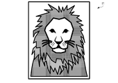
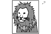
- the display body adopting this structure can display, for example, a face image of a person or an animal (for example, a lion and a zebra) as a diffraction image with high definition and medium vividness. That is, the display body adopting the above structure can display a diffraction image that gives a natural impression to the observer.
- a display body adopting this structure can suitably display an image of a person or an animal, particularly a mammal.
- the first to sixth sub-regions include an arrangement direction of the first ridge or groove and an arrangement direction of the second ridge or groove.
- Each has a shape extending in an intersecting first direction, and the first sub region and the fourth sub region are arranged in a second direction intersecting the first direction, and the second sub region and the The fifth sub-region is arranged in the second direction, the third sub-region and the sixth sub-region are arranged in the second direction, and the first sub-region and the fourth sub-region are The column formed, the column formed by the second sub region and the fifth sub region, and the column formed by the third sub region and the sixth sub region are arranged in the second direction.
- the display body adopting this structure can display an image of a solid or colorful object such as a building, a flower, and an animal (for example, a bird and a tropical fish) as a diffraction image.
- a display body employing this structure can suitably display images of buildings, flowers, birds, tropical fish, and insects.
- the first to sixth sub-regions include an arrangement direction of the first ridge or groove and an arrangement direction of the second ridge or groove.
- Each has a shape extending in an intersecting first direction
- the first to third sub-regions are arranged in a second direction intersecting the first direction
- the fourth to sixth sub-regions are A column formed in the second direction and formed by the first to third sub-regions and a column formed by the fourth to sixth sub-regions are arranged in the first direction and the first sub-region
- the fourth sub-region is adjacent in the first direction
- the second sub-region and the fifth sub-region are adjacent in the first direction
- the third sub-region and the sixth sub-region are the A display body according to the above-mentioned side surface adjacent to the first direction is provided.
- a display body employing this structure is suitable for displaying an image with a weak sense of depth as a diffraction image.
- a display body adopting this structure can suitably display solid characters, cameos, and coin images.
- each of the first to sixth sub-regions is any one of the above-described side surfaces, wherein a ratio of the dimension in the first direction to the dimension in the second direction is in the range of 1 to 5.
- the distance between adjacent ones of the first to sixth sub-regions is 300 ⁇ m or less. Provided.
- the distance between adjacent ones of the first to sixth sub-regions is 300 ⁇ m or less. Provided. According to still another aspect of the present invention, in each of the plurality of pixels, the distance between adjacent ones of the first to sixth sub-regions is 50 ⁇ m or less. Provided.
- a relief structure forming layer having a relief structure on a surface and a reflective layer covering the surface are provided, and the relief structure includes the relief structure forming layer and the reflective layer.
- a relief structure forming layer having a relief structure on a surface and a reflective layer covering the surface are provided, and the relief structure includes the relief structure forming layer and the reflective layer.
- thermoplastic resin for example, a thermoplastic resin, a thermosetting resin, or an ultraviolet ray or an electron beam curable resin
- thermoplastic resin an acrylic resin, an epoxy resin, a cellulose resin, or a vinyl resin
- thermosetting resin urethane resin, melamine resin, or phenol resin obtained by adding polyisocyanate as a crosslinking agent to acrylic polyol or polyester polyol having a reactive hydroxyl group and crosslinking
- an acrylic resin can be used.
- acrylic resin for example, epoxy acryl, epoxy methacryl, urethane acrylate, or urethane methacrylate can be used.
- the relief structure forming layer can be formed by the following method. For example, an original plate provided with a relief structure is pressed against a thermoplastic resin layer while applying heat, and then the original plate is removed (separated) from the thermoplastic resin layer.
- a coating film made of an ultraviolet curable resin is formed on a support or carrier, and the ultraviolet curable resin is cured by irradiating ultraviolet rays while pressing the original plate on the support or carrier, and then the original plate is removed (released) from the coating film. ).
- a coating film made of a thermosetting resin is formed, and the thermosetting resin is cured by heating while pressing the original plate against the original, and then the original plate is removed (released) from the coating film.
- the thickness of the relief structure forming layer can be, for example, 1 ⁇ m or more and 25 ⁇ m or less.
- ⁇ Metal can be used as the material of the reflective layer.
- a metal layer made of a metal material such as aluminum, silver, gold, and alloys thereof can be used.
- a dielectric layer having a refractive index different from that of the relief structure forming layer can be used as the reflective layer.
- a laminate of dielectric layers having different refractive indexes between adjacent ones, that is, a dielectric multilayer film can be used.
- the refractive index of those in contact with the relief structure forming layer is preferably different from the refractive index of the relief structure forming layer.
- the reflective layer can be formed by physical deposition and / or chemical deposition.
- a physical vapor deposition method such as a vacuum evaporation method or a sputtering method can be applied.
- An inorganic compound or an organic compound can be used for the dielectric layer or the dielectric multilayer film.
- a multilayer film formed of a dielectric layer made of an inorganic compound or an organic compound and a metal layer can be used as the reflective layer.
- oxides, sulfides, fluorides and nitrides can be used.
- oxide for example, a metal oxide or silicon oxide (SiO) can be used.
- fluoride a metal fluoride can be used.
- nitride for example, a metal nitride can be used.
- sulfide for example, a metal sulfide can be used.
- metal oxide for example, titanium oxide (TiO), zinc oxide (ZnO), or alumina can be used.
- ZnS zinc sulfide
- AlS aluminum sulfide
- nitride for example, calcium nitride (CaN) or magnesium nitride (MgN) can be used.
- metal fluoride magnesium fluoride (MgF) or calcium fluoride (CaF) can be used.
- the reflective layer covers part or all of the relief structure surface, which is the principal surface on which the relief structure is formed, of the two principal surfaces of the relief structure forming layer.
- a pattern corresponding to the contour shape of the reflective layer can be displayed.
- the pattern displayed by the outline of the reflective layer may be related to the pattern displayed by the relief structure.
- the pattern displayed by the outline of the reflective layer can be a pattern that borders the relief structure.
- the reflective layer may be a layer that does not transmit visible light.
- the reflective layer may be a layer having visible light transparency, for example, a transparent layer such as a transparent vapor deposition layer.
- the “layer having visible light transmission” means a layer having an optical density (OD) of 1.5 or less with respect to light having a wavelength of 550 nm.
- the “optical density (OD)” is a value calculated from the following equation when the intensity of incident light having the above wavelength is I 0 and the intensity of transmitted light having the above wavelength is I 1 .
- the reflective layer is a layer having visible light permeability
- a part of the illumination light is reflected by the reflective layer, and the other part of the illumination light is transmitted through the reflective layer.
- a part of the light transmitted through the reflected light is reflected by the article located behind the display body and is transmitted through the reflective layer again. That is, the light reflected by the article located behind the display body can also contribute to the display.
- an article with a display body described later has a print pattern at the position of the display body, an image formed by superimposing an image displayed on the display body and an image displayed on the print pattern is displayed. It is possible. It is difficult to forge an article with a display body that displays such an image or to reproduce such an image with a duplicate.
- the “article with display” is also referred to as “labeled article”.
- a reflective protective layer may be provided on the surface of the reflective layer opposite to the relief structure surface.
- an inorganic compound, a polymer, or a combination thereof can be used.
- an oxide or a nitride can be used.
- the oxide is, for example, silicon oxide (SiO) or alumina
- the nitride is, for example, calcium nitride (CaN), titanium nitride (TiN), or aluminum nitride (AlN).
- the polymer is, for example, a urethane resin or an acrylic resin.
- the thickness of the reflective layer can be, for example, 10 nm or more and 500 nm or less.
- a transfer foil comprising a transfer material layer including the display body according to any one of the above aspects, and a support or carrier that detachably supports the transfer material layer.
- the transfer material layer includes a transfer portion and a non-transfer portion that are adjacent to each other.
- the transfer portion is a portion of the transfer material layer that is transferred to the article, and includes the display body.
- the non-transfer portion is a portion of the transfer material layer that remains without being transferred to the article.
- the non-transfer portion has the same layer configuration as the transfer portion.
- the support or carrier is, for example, a resin (plastic) film or a resin (plastic) sheet.
- a thermoplastic can be used as the support or carrier.
- a material having excellent heat resistance such as polyethylene terephthalate can be used.
- a release layer containing, for example, a fluororesin or a silicone resin may be provided on the main surface supporting the transfer material layer of the support or carrier.
- the thickness of the support or carrier can be 4 ⁇ m or more and 50 ⁇ m or less.
- the transfer foil according to the above aspect, wherein the transfer material layer further includes a peeling protective layer interposed between the display body and the support.
- the peeling protection layer facilitates peeling of the transfer portion from the support or carrier, and plays a role of protecting the peeled transfer portion, that is, the surface of the display body from damage and deterioration.
- the peeling protective layer has light transmittance, for example.
- the peeling protective layer is made of, for example, a resin.
- the resin constituting the peeling protection layer is, for example, an ultraviolet curable resin, a thermosetting resin, or a thermoplastic resin. As this resin, for example, an acrylic resin can be used.
- the thickness of the peeling protective layer can be set to, for example, 0.5 ⁇ m or more and 5 ⁇ m or less.
- the peeling protective layer may contain a powder.
- the powder can be any of silica powder, silicone powder, fluororesin powder, polyester powder, acrylic powder, and ETFE resin powder, or a blend containing two or more thereof.
- ETFE is an abbreviation for a copolymer of ethylene and tetrafluoroethylene.
- a transfer foil further comprising an adhesive layer covering the transfer material layer.
- the adhesive layer is made of, for example, a thermoplastic resin.
- a thermoplastic resin a polyethylene resin, a polyester resin, an acrylic resin, or an olefin resin can be used.
- the thickness of the adhesive layer can be, for example, not less than 0.5 ⁇ m and not more than 20 ⁇ m.
- an adhesive label comprising a display body according to any of the above aspects and an adhesive layer provided on one main surface of the display body.
- the adhesive layer is made of an adhesive such as a pressure sensitive adhesive.
- an adhesive such as a pressure sensitive adhesive.
- vinyl chloride-vinyl acetate copolymer, polyester polyamide, or acrylic, butyl rubber, natural rubber, silicone or polyisobutyl adhesive can be used.
- the pressure-sensitive adhesive may further contain an additive.
- Additives include aggregation components such as alkyl methacrylates, vinyl esters, acrylonitrile, styrene and vinyl monomers; modifying components such as unsaturated carboxylic acids, hydroxy group-containing monomers and acrylonitrile; polymerization initiators; plasticizers; curing agents Curing accelerators; antioxidants; or mixtures containing two or more thereof can be used.
- an article with a display comprising the display according to any of the above aspects and an article that supports the display.
- the article may support the display body by any method.
- the display body may be affixed on the surface of the article, or may be embedded in the article.
- the article with a display body may be a product obtained by transferring a display body from a transfer foil provided with a display body to the surface of the article, or a label having a display body attached thereto.
- an article with a display body is a product provided with an article surface layer so as to cover the display body by transferring the display body from the transfer foil provided with the display body to the surface of the article body, or a label provided with the display body.
- An article surface layer may be provided so as to be attached to the surface of the main body and cover the label.
- the article has a shape extending in one direction, and the center of the display body is from a plane passing through the center of the article and perpendicular to the length direction of the article.
- the display body according to the above-described side surface, wherein the line segments that are spaced apart and extend from the center of the display body and equally divide the angular range of the diffracted light emitted from the first sub-pixel are inclined toward the plane An attached article is provided.
- the article has a shape extending in one direction, and the center of the display body is from a plane passing through the center of the article and perpendicular to the length direction of the article.
- a line segment that is spaced apart and extends from the center of the display body and equally divides the angle range of the diffracted light emitted from the diffraction grating for wide-range display relates to the side surface that is inclined toward the plane.
- the article includes a printed pattern, the printed pattern displays a character, and the center of the display body passes through the center of the article and the width direction of the character.
- the line segment extending from the center of the display body and equally dividing the angular range of the diffracted light emitted from the first sub-pixel is inclined toward the plane.
- An article with a display body according to a side surface is provided.
- the article includes a printed pattern, the printed pattern displays characters, and the center of the display body passes through the center of the article and is perpendicular to the width direction of the characters.
- the line segment that is separated from the flat plane and extends from the center of the display body and equally divides the angular range of the diffracted light emitted from the diffraction grating for wide-range display is inclined toward the plane.
- An article with a display body according to a side surface is provided.
- the observer When the article includes a printed pattern and the printed pattern displays characters, the observer usually observes the article with the display body so that the width direction of the characters is parallel to the line connecting the eyes of the observer. To do. Then, the observer usually observes the article with the display body so that the center of the article is positioned on a plane that passes through the middle point between both eyes and is perpendicular to the line connecting both eyes. Therefore, when the center of the display body is separated from the plane, if the previous line segment is tilted as described above, the observer can display the display body under normal observation conditions for observing the article, for example. The brightest image to be displayed can be perceived. Therefore, an article with a display body that employs the above configuration is easy to visually recognize an image displayed on the display body.
- the article is provided with the display body according to the above aspect from plastic, metal, paper, or a composite thereof.
- the article includes paper, the display body is inserted into the paper, and the paper is open at the position of the display body.
- An attached article is provided.
- the article with a display body is a package in which a personal authentication medium such as banknotes, securities, certificates, credit cards, passports and ID (identification) cards, and contents are packaged.
- a personal authentication medium such as banknotes, securities, certificates, credit cards, passports and ID (identification) cards, and contents are packaged.
- FIG. 4 is an enlarged schematic plan view illustrating an example of a first sub-pixel included in the pixel of FIG.
- FIG. 4 is an enlarged schematic plan view showing an example of a second sub-pixel included in the pixel of FIG.
- FIG. 4 is an enlarged schematic plan view showing an example of a third sub-pixel included in the pixel of FIG.
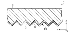
- the expanded sectional view which shows roughly the display body of FIG.1 and FIG.2.
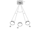
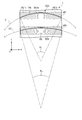
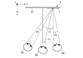
- FIG.1 and FIG.2 Schematic which shows a mode that the observer is observing the display body of FIG.1 and FIG.2.
- FIG. 3 is an enlarged plan view schematically showing an example of a structure that can be adopted for a sub-pixel.
- FIG. 6 is an enlarged plan view schematically showing another example of a structure that can be adopted for a sub-pixel.
- the top view which expands and shows a part of display body which concerns on 3rd Embodiment of this invention The top view which expands and shows an example of the pixel which the display body of FIG. 20 contains.
- the first embodiment is a more specific one of the above-described side surfaces.
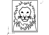
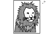
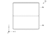
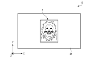
- FIG. 1 is a plan view schematically showing a display body according to a first embodiment of the present invention.
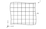
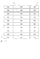
- FIG. 2 is an enlarged plan view showing a part of the display body of FIG.
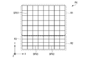
- FIG. 3 is an enlarged plan view showing pixels included in the display body of FIGS. 1 and 2.
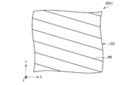
- 4 is an enlarged schematic plan view showing an example of the first sub-pixel included in the pixel of FIG.
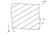
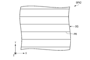
- FIG. 5 is an enlarged schematic plan view showing an example of the second sub-pixel included in the pixel of FIG.
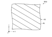
- FIG. 6 is a schematic plan view showing an example of the third sub-pixel included in the pixel of FIG. 3 in an enlarged manner.
- FIG. 7 is an enlarged cross-sectional view schematically showing the display body of FIGS. 1 and 2.
- the cross section shown in FIG. 7 is a cross section taken along the line VII-VII of the structure shown in FIG. 1 to 7, the X direction and the Y direction are directions parallel to the main surface of the display body 1 and orthogonal to each other.
- the X direction and the Y direction are the horizontal direction and the vertical direction of the display body 1, respectively.
- the Z direction is a direction perpendicular to the X direction and the Y direction, and is the thickness direction of the display body 1.
- the display 1 shown in FIGS. 1, 2 and 7 includes a relief structure forming layer 11 and a reflective layer 12 as shown in FIG.
- This display body 1 is the front surface on which the relief structure forming layer 11 side faces the observer, and the reflective layer 12 side is the back surface.
- the display body 1 may be the front surface on the reflective layer 12 side facing the viewer, and the relief structure forming layer 11 side may be the back surface.
- the reflective layer 12 is placed in contact with the relief surface of the relief structure forming layer 11.
- the display body 1 includes a plurality of pixels PX arranged in directions crossing each other.
- the pixels PX are arranged in the X direction and the Y direction. At least one arrangement direction of the pixels PX may be oblique with respect to the X direction and the Y direction.
- Each pixel PX includes a first region R1, a second region R2, and a third region R3 as shown in FIG.
- the area of the first region R1 may be equal to or smaller than the areas of the second region R2 and the third region R3. However, the area of the first region R1 is preferably larger than the areas of the second region R2 and the third region R3.
- the “low-angle observation condition” is an observation condition in which the angle formed by the Z direction with respect to a plane perpendicular to the line segment connecting both eyes of the observer is small.
- the arrangement of the first region R1 is, for example, from the state in which the Z direction is parallel to a plane perpendicular to the line segment connecting the eyes of the observer, while keeping the illumination direction, the observation direction, and the Y direction constant.
- the angle formed by the Z direction with respect to the previous plane is increased, a plurality of images having slightly different shapes and positions are sequentially displayed.
- Each first region R1 includes a plurality of first sub-pixels SPX1.
- Each of the first sub-pixels SPX1 emits no diffracted light or emits the first diffracted light within a first angle range when illuminated with illumination light from the normal direction.
- One first sub-pixel SPX1 included in each pixel PX is used as an image element included in one of a plurality of images to be displayed by the arrangement of the first region R1.
- the other first sub-pixel SPX1 included in each pixel PX is used as an image element included in another one of the plurality of images to be displayed by the arrangement of the first region R1.
- each of the plurality of first sub-pixels SPX1 included in each pixel PX corresponds to an image element of a plurality of images to be displayed by the arrangement of the first region R1.
- the first sub-pixel SPX1 that does not emit diffracted light does not include a diffraction grating.
- the first sub-pixel SPX1 that emits the first diffracted light includes, for example, the diffraction grating DG shown in FIG.
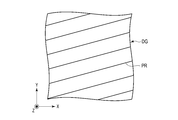
- This diffraction grating DG is a relief type diffraction grating composed of a plurality of edges or grooves PR arranged in the width direction.
- the first sub-pixels SPX1 have slightly different ridges of the diffraction grating DG or length directions of the grooves PR. ing.
- the angle formed by the length direction of the ridge or groove PR with respect to the X direction is, for example, in the range of ⁇ 1 to + ⁇ 1 (0 ° ⁇ 1 ).
- a clockwise angle with respect to the X direction is positive, and a counterclockwise angle with respect to the X direction is negative.
- the “wide-angle observation condition” is an observation condition in which the angle formed by the Z direction with respect to a plane perpendicular to the line segment connecting both eyes of the observer is large.
- the arrangement of the second region R2 is, for example, from the state in which the Z direction is tilted with respect to a plane perpendicular to the line segment connecting both eyes of the observer, while keeping the illumination direction, the observation direction, and the Y direction constant.
- the arrangement of the third region R3, for example, keeps the illumination direction, the observation direction, and the Y direction constant from a state in which the Z direction is tilted in the opposite direction with respect to a plane perpendicular to the line segment connecting the eyes of the observer. If the angle formed by the Z direction with respect to the previous plane is increased, a plurality of images having slightly different shapes and positions are sequentially displayed.
- the second region R2 includes a plurality of second subpixels SPX2.
- Each of the second sub-pixels SPX2 does not emit diffracted light when illuminated with illumination light from the normal direction, or the second diffracted light is emitted within a second angle range wider than the first angle range.
- the light is emitted with an intensity lower than that of the first diffracted light.
- the intensity of the second diffracted light is made lower than the intensity of the first diffracted light by making the area of each second subpixel SPX2 smaller than the area of each first subpixel SPX1.
- One second sub-pixel SPX2 included in each pixel PX is used as an image element included in one of a plurality of images to be displayed by the array of the second region R2.
- the other second sub-pixel SPX2 included in each pixel PX is used as an image element included in the other one of the plurality of images to be displayed by the array of the second region R2.
- each of the plurality of second sub-pixels SPX2 included in each pixel PX corresponds to an image element of a plurality of images to be displayed by the arrangement of the second region R2.
- the second sub-pixel SPX2 that does not emit diffracted light does not include a diffraction grating.
- the second sub-pixel SPX2 that emits the second diffracted light includes, for example, the diffraction grating DG shown in FIG.
- This diffraction grating DG is a relief type diffraction grating composed of a plurality of edges or grooves PR arranged in the width direction.
- the second subpixels SPX2 are slightly different in the length direction of the edges of the diffraction grating DG or the grooves PR. ing.
- the angle formed by the length direction of the ridge or groove PR with respect to the X direction is, for example, in the range of ⁇ 2 to ⁇ 1 ( ⁇ 1 ⁇ 2 ⁇ 90 °). Is in.
- the third region R3 includes a plurality of third sub-pixels SPX3.
- the third sub-pixel SPX3 When each of the third sub-pixels SPX3 is illuminated with illumination light from the normal direction, the third sub-pixel SPX3 does not emit diffracted light, or the third diffracted light is separated from the second angle range with the first angle range in between. The light is emitted within the third angle range adjacent to each other and with lower intensity than the first diffracted light.
- the intensity of the third diffracted light is made lower than the intensity of the first diffracted light by making the area of each third subpixel SPX3 smaller than the area of each first subpixel SPX1.
- One third sub-pixel SPX3 included in each pixel PX is used as an image element included in one of a plurality of images to be displayed by the arrangement of the third region R3.
- the other third sub-pixel SPX3 included in each pixel PX is used as an image element included in another one of the plurality of images to be displayed by the arrangement of the third region R3.
- the plurality of third sub-pixels SPX3 included in each pixel PX correspond to the image elements of the plurality of images to be displayed by the arrangement of the third region R3, respectively.
- the third sub-pixel SPX3 that does not emit diffracted light does not include a diffraction grating.
- the third sub-pixel SPX3 that emits the third diffracted light includes, for example, the diffraction grating DG shown in FIG.
- This diffraction grating DG is a relief type diffraction grating composed of a plurality of edges or grooves PR arranged in the width direction.
- the third sub-pixels SPX3 are slightly different in the length direction of the edge of the diffraction grating DG or the groove PR. ing.
- the angle formed by the length direction of the ridge or groove PR with respect to the X direction is in the range of + ⁇ 1 to + ⁇ 2 , for example.
- the display 1 displays a certain image with a certain sub-pixel group distributed over a plurality of pixels PX, and displays another image with another sub-pixel group distributed over a plurality of pixels PX. Designed to be. And this display body 1 is maintaining the illumination direction, the observation direction, and the Y direction from the state which made the Z direction parallel with respect to the plane perpendicular
- This display body 1 can display a continuously changing image within a wide angle range without giving an uncomfortable feeling to the observer. This will be described with reference to FIGS.
- FIG. 8 is a schematic view showing a state in which an observer observes the display body shown in FIGS. 1 and 2.
- FIG. 9 is a diagram illustrating an example of an image displayed when the display body according to the comparative example is observed from the front.
- FIG. 10 is a diagram illustrating an example of an image displayed when the display body according to the comparative example is observed from the diagonally right direction.
- FIG. 11 is a diagram illustrating an example of an image displayed when the display body according to the comparative example is observed from the left oblique direction.
- FIG. 12 is a diagram illustrating an example of an image displayed when the display body according to the comparative example is observed at a deeper angle from the right oblique direction.
- FIG. 9 is a diagram illustrating an example of an image displayed when the display body according to the comparative example is observed from the front.
- FIG. 10 is a diagram illustrating an example of an image displayed when the display body according to the comparative example is observed from the diagonally right direction.
- FIG. 11
- FIG. 13 is a diagram illustrating an example of an image displayed when the display body according to the comparative example is observed at a deeper angle from the diagonal left direction.
- FIG. 14 is a diagram illustrating an example of an image displayed on the display body in FIGS. 1 and 2 under the same conditions as in FIG.
- FIG. 15 is a diagram illustrating an example of an image displayed on the display body in FIGS. 1 and 2 under the same conditions as in FIG.
- the display according to the comparative example displays an image described below.
- the display body according to the comparative example all of the first sub-pixel SPX1, the second sub-pixel SPX2, and the third sub-pixel SPX3 that emit diffracted light have the same wavelength under the same front condition. Further, it is assumed that the diffracted light having the same intensity is emitted.
- the display body When the normal line of the display body is slightly tilted to the right with respect to a plane perpendicular to the line segment connecting both eyes of the observer, the display body displays, for example, an image I2a shown in FIG. Further, when the normal line of the display body is slightly tilted to the left with respect to a plane perpendicular to the line segment connecting both eyes of the observer, the display body can display, for example, an image I3a shown in FIG.
- the display body displays an image I2b ′ shown in FIG.
- the display body can display an image I3b ′ shown in FIG.
- the display body according to the comparative example displays the normal image and the ghost image. An unclear image is displayed due to the overlap.
- the display body 1 described with reference to FIGS. 1 to 7 has a configuration in which the second and third diffracted lights have lower intensity than the first diffracted light.
- the display body 1 can display the image I2b shown in FIG. That is, the display body 1 can display a darker image I2b as compared with the image I2b 'of FIG.
- the display body 1 can display the image I3b shown in FIG. That is, the display body 1 can display a darker image I3b as compared with the image I3b 'of FIG.
- the display body 1 can display a continuously changing image within a wide angle range without giving the viewer a sense of incongruity.
- the image displayed on the display body 1 can be, for example, a security pattern, an identification pattern, or an authentication pattern.
- the security pattern include a three-dimensional image, a geometric pattern, a landmark, a landscape, and a portrait, a bust, a sculpture, an animal, a bird, a tropical fish, and an insect.
- the portrait is an image that is easy to perceive the difference as a sense of incongruity even if the difference between the portrait displayed by the genuine product and the portrait displayed by the counterfeit product is slight, particularly when the portrait is a high-definition image. Therefore, the display body 1 that displays a portrait easily determines authenticity.
- the display body 1 that displays landmarks, landscapes, and the like is easy to determine authenticity.
- the second embodiment is a more specific one of the above-described side surfaces.
- FIG. 16 is an enlarged plan view showing pixels included in the display body according to the second embodiment of the present invention.
- the display body according to the second embodiment is the same as the display body 1 according to the first embodiment except that the structure described below is adopted for the pixel PX.
- each pixel PX includes a wide area display area RA and a narrow area display area RB.
- a plurality of images to be displayed by the display body 1 are recorded under observation conditions from a low angle to a wide angle.
- the region RA is arranged in such a manner that the illumination direction, the observation direction, and the Y direction are kept constant from a state in which the Z direction is greatly inclined with respect to a plane perpendicular to the line segment connecting both eyes of the observer.
- the direction is greatly tilted in the opposite direction, a plurality of images having slightly different shapes and positions are sequentially displayed.
- the region RA includes a region R1a and the second region R2 and the third region R3 described in the first embodiment.
- the arrangement of the region R1a is, for example, from the state in which the Z direction is parallel to a plane perpendicular to the line connecting the eyes of the observer, while the illumination direction, the observation direction, and the Y direction are kept constant.
- the angle formed by the Z direction with respect to the plane is increased, a plurality of images having slightly different shapes and positions are sequentially displayed.
- Each region R1a includes a plurality of sub-pixels SPX1a.
- Each of the sub-pixels SPX1a emits no diffracted light or emits the first diffracted light within the first angle range when illuminated with illumination light from the normal direction.
- One subpixel SPX1a included in each pixel PX is used as an image element included in one of a plurality of images to be displayed by the array of the region R1a. Further, the other sub-pixel SPX1a included in each pixel PX is used as an image element included in another one of the plurality of images to be displayed by the arrangement of the region R1a. Thus, the plurality of sub-pixels SPX1a included in each pixel PX correspond to the image elements of the plurality of images to be displayed by the arrangement of the region R1a.
- the sub-pixel SPX1a that does not emit diffracted light does not include a diffraction grating.
- the sub-pixel SPX1a that emits the first diffracted light includes, for example, the diffraction grating DG shown in FIG.
- This diffraction grating DG is a relief type diffraction grating composed of a plurality of edges or grooves PR arranged in the width direction.
- the subpixels SPX1a are slightly different in the length direction of the edge of the diffraction grating DG or the groove PR.
- the angle formed by the length direction of the ridge or groove PR with respect to the X direction is in the range of ⁇ 1 to + ⁇ 1 , for example.
- the sub-pixel SPX1a, the second sub-pixel SPX2, and the third sub-pixel SPX3 have the same area.
- the intensity of the first diffracted light emitted from the subpixel SPX1a is equal to, for example, the intensity of the second and third diffracted lights emitted from the second subpixel SPX2 and the third subpixel SPX3, respectively.
- the region RB In the arrangement of the region RB, a plurality of images to be displayed by the display body 1 under a low-angle observation condition are recorded.
- the arrangement of the region RB is, for example, from the state in which the Z direction is parallel to a plane perpendicular to the line segment connecting both eyes of the observer, while keeping the illumination direction, the observation direction, and the Y direction constant.
- the angle formed by the Z direction with respect to the plane is increased, a plurality of images having slightly different shapes and positions are sequentially displayed.
- Each region RB includes a plurality of sub-pixels SPX1b.
- Each of the sub-pixels SPX1b does not emit diffracted light or emits first diffracted light within the first angle range when illuminated with illumination light from the normal direction.
- One subpixel SPX1b included in each pixel PX is used as an image element included in one of a plurality of images to be displayed in the array of the region RB. Further, the other sub-pixel SPX1b included in each pixel PX is used as an image element included in another one of the plurality of images to be displayed in the array of the region RB. Thus, the plurality of sub-pixels SPX1b included in each pixel PX correspond to the image elements of the plurality of images to be displayed by the array of the regions RB.
- the sub-pixel SPX1b that does not emit diffracted light does not include a diffraction grating.
- the sub-pixel SPX1b that emits the first diffracted light includes, for example, the diffraction grating DG shown in FIG.
- This diffraction grating DG is a relief type diffraction grating composed of a plurality of edges or grooves PR arranged in the width direction.
- the subpixels SPX1b are slightly different in the length direction of the edge of the diffraction grating DG or the groove PR.
- the angle formed by the length direction of the ridge or groove PR with respect to the X direction is in the range of ⁇ 1 to + ⁇ 1 , for example.
- the sub-pixel SPX1b that emits the first diffracted light is different from the sub-pixel SPX1a that emits the first diffracted light at an angle formed by the ridge of the diffraction grating DG or the length direction of the groove PR with respect to the X direction.
- One or more of the sub-pixels SPX1b that emit the first diffracted light has the same angle as the sub-pixel SPX1a that emits the first diffracted light and the ridge of the diffraction grating DG or the length direction of the groove PR with respect to the X direction. Also good.
- the area of the sub-pixel SPX1b is equal to the area of the sub-pixel SPX1a.
- the area of the subpixel SPX1b may be different from the area of the subpixel SPX1a.
- the display body according to the second embodiment can also display a continuously changing image within a wide angle range without giving the viewer a sense of incongruity. This will be described below.
- the change in the first image according to the observation direction becomes smooth.
- the smoothness of the change in the second image corresponding to the observation direction is lowered.
- the smoothness of the change in the third image corresponding to the observation direction is reduced.
- the ratio of the total area of the second and third sub-pixels occupying the area of each pixel can be reduced, and thereby the total of the sub-pixels SPX1a and SPX1b occupying the area of each pixel.
- the area ratio can be increased. Therefore, according to this display body, for example, the change in the first image can be smoothed without giving the viewer a sense of incongruity. That is, this display body can display a continuously changing image within a wide angle range without giving the viewer a sense of incongruity.
- Tables 1 and 2 show configurations that can be employed in the display bodies according to Comparative Examples 1 and 2, respectively.
- Table 3 shows the configuration of the display body according to Example 1.
- Tables 4 and 5 show the configurations of the display bodies according to Example 2.
- Table 6 shows an outline of the configuration employed in the display bodies according to Comparative Examples 1 and 2 and Examples 1 and 2.
- angle range represents a difference between the maximum value and the minimum value of the angle formed by the length direction of the ridge or groove of the diffraction grating provided in the sub-pixel with respect to the horizontal direction of the display body.
- angle difference represents a difference between sub-pixels at an angle formed by the length direction of the ridge or groove of the diffraction grating provided in the sub-pixel with respect to the horizontal direction of the display body.
- Table 1 shows an example of a configuration that can be adopted when 30 subpixels are arranged in each pixel as Comparative Example 1. Specifically, Table 1 shows the minimum and maximum angles formed by the ridges or grooves of the diffraction grating provided in 30 subpixels in the display according to the comparative example with respect to the horizontal direction of the display. When the values are ⁇ 25 ° and + 25 °, respectively, it is shown how the previous angle should be set in each sub-pixel.
- the difference in the angle between the sub-pixels is as shown in Table 6. More than 1.7 °. That is, in this configuration, the difference in the emission angle of diffracted light between the sub-pixels is large. Therefore, the image displayed by the display body adopting this configuration does not change smoothly when the observation direction or the like is changed. In addition, when this configuration is employed, the image may appear blurred due to the overlap between the normal image and the ghost image.
- the display body adopting this configuration can diffract light only in a low angle region. Eject. For this reason, the influence of the overlap between the normal image and the ghost image on the sharpness of the image is sufficiently small.
- the difference in angle between the sub-pixels can be made smaller than that in the display body according to Comparative Example 1.
- the difference in angle between sub-pixels exceeds 1 °. That is, even in this configuration, the difference in the exit angle of the diffracted light between the sub-pixels is large. Therefore, the image displayed by the display body adopting this configuration does not change smoothly when the observation direction or the like is changed.
- the display body adopting such a configuration gives a viewer a sense of incongruity.
- Table 2 shows an example of a configuration that can be adopted as Comparative Example 2 when 50 subpixels are arranged in each pixel. Specifically, Table 2 shows the minimum value and the maximum value of the angle formed by the length direction of the ridge or groove of the diffraction grating provided in the 50 sub-pixels with respect to the horizontal direction of the display body in the comparative example. When the values are ⁇ 25 ° and + 25 °, respectively, it is shown how the previous angle should be set in each sub-pixel.
- Table 3 shows an example of a configuration that can be employed in the pixel PX of FIG.
- six second subpixels SPX2, six third subpixels SPX3, eighteen subpixels SPX1a, and thirty subpixels SPX1b are arranged in each pixel PX.
- the first to sixth sub-pixels are the third sub-pixel SPX3
- the seventh to 24th sub-pixels are the sub-pixel SPX1a
- the 25th to 30th sub-pixels are the 2 sub-pixels SPX2.
- the 31st to 60th sub-pixels are sub-pixels SPX1b.
- the angle formed by the ridge of the diffraction grating DG or the length direction of the groove PR included in each of the sub-pixels SPX1a and SPX1b with respect to the X direction is in the range of ⁇ 15 ° to + 15 °.
- the difference in angle between the subpixels SPX1a and SPX1b is less than 1 ° on average. That is, the difference in the exit angle of the diffracted light is sufficiently small between the sub-pixels SPX1a and SPX1b. Therefore, the image displayed by the display body adopting this configuration changes smoothly when the observation direction or the like is changed in the low angle region.
- the display body adopting this configuration since the sub-pixels SPX1a and SPX1b emit diffracted light only in the low angle region, the clearness of the image displayed by the sub-pixels SPX1a and SPX1b is increased between the normal image and the ghost image. The effect of overlap is small enough.
- the sub-pixels SPX1a and SPX1b emit diffracted light in a low angle region, while the second sub-pixel SPX2 and the third sub-pixel SPX3 emit diffracted light in a wide angle region. Therefore, even if the observation direction or the like is greatly changed, the observer can perceive changes in the shape and position of the image.
- the continuous change image expressed in the wide angle range is darker than the continuous change image expressed in the low angle range. Therefore, in the wide angle range, even if the smoothness of the change in the image is low, it is unlikely that the observer will feel uncomfortable, and blurring due to the overlap between the normal image and the ghost image is not perceived.
- the ratio of the total area of the second subpixel SPX2 and the third subpixel SPX3 occupying the area of each pixel PX can be reduced.
- the ratio of the total area of the subpixels SPX1a and SPX1b in the area can be increased. Therefore, according to this display body, for example, the change of the image can be smoothed without giving the viewer a sense of incongruity. That is, this display body can display a continuously changing image within a wide angle range without giving the viewer a sense of incongruity.
- Table 4 and Table 5 show other examples of configurations that can be employed in the pixel PX of FIG.
- ten second subpixels SPX2, ten third subpixels SPX3, thirty subpixels SPX1a, and fifty subpixels SPX1b are arranged in each pixel PX.
- the first to tenth sub-pixels are the third sub-pixel SPX3
- the eleventh to fortieth sub-pixels are the sub-pixel SPX1a
- the 41st to 50th sub-pixels are the 2 sub-pixels SPX2.
- the 51st to 100th sub-pixels are sub-pixels SPX1b.
- this display body similarly to the display body according to the first embodiment, for example, it is possible to smooth the change of the image without giving an uncomfortable feeling to the observer. That is, this display body can display a continuously changing image within a wide angle range without giving the viewer a sense of incongruity.
- this display body more sub-pixels are arranged in each pixel as compared with the display body according to the first embodiment. Therefore, according to this display body, compared with the display body according to the first embodiment, it is possible to make the image change more smoothly when the observation direction or the like is changed.
- FIG. 17 is an enlarged plan view schematically showing an example of a structure that can be employed in the sub-pixel.
- FIG. 18 is an enlarged plan view schematically showing another structure that can be employed in the sub-pixel.
- the diffraction grating DG is composed of linear ridges or grooves PR.
- the ridge or groove PR may not be linear.
- the ridge or groove PR may have a curved shape such as an arc shape.
- the length direction of the ridge or groove PR is the length direction of the approximate straight line of the curve.
- the third embodiment is a more specific one of the above-described side surfaces.
- FIG. 19 is an enlarged plan view showing pixels included in the display body according to the third embodiment of the present invention.
- FIG. 20 is an enlarged plan view showing a part of the display body according to the third embodiment of the present invention.
- FIG. 21 is an enlarged plan view showing an example of a pixel included in the display body of FIG.
- FIG. 22 is an enlarged plan view showing another example of pixels included in the display body of FIG.
- FIG. 23 is a plan view showing the relationship between the pixel shown in FIG. 21 and the first and second arcs.
- FIG. 24 is a plan view illustrating a relationship between a pixel and first and second arcs according to a modification.
- the wide-range display area RA and the narrow-range display area RB are drawn away from each other for easy viewing.
- the wide display area RA and the narrow display area RB may be separated from each other or may be adjacent to each other.
- the display body according to the third embodiment is the same as the display body according to the second embodiment except that the structure described below is adopted for the pixel PX.
- the wide-range display region RA shown in FIG. 19 does not include the diffraction grating, or the wide-range display diffraction grating DG1 shown in FIGS. Contains.
- the diffraction grating DG1 includes ridges or grooves PR (first ridges or grooves) that are curved in an arc shape and arranged in the width direction (Y direction). Arc first edge or the groove is formed, either a first arc AR1 having a first central angle phi 1 shown in FIG. 23, or a part of the first arc AR1.
- the narrow range display region RB shown in FIG. 19 does not include the diffraction grating, or includes the narrow range display diffraction grating DG2 shown in FIGS.
- the diffraction grating DG2 includes ridges or grooves PR (second ridges or grooves) that are curved in an arc shape and are arranged in the width direction (Y direction). Arc second edge or a groove is formed, or a second arc AR2 having a second central angle phi 2 as shown in FIG. 23, or a part of the second arc AR2.
- the first arc AR1 translates the ridge or groove PR included in the plurality of pixels PX and the one included in the wide-range display region RA (first ridge or groove) shown in FIG.
- the smallest arc including one or more curves obtained by superimposing them.
- any pixel PX as shown in FIGS. 21 and 23, when the diffraction grating DG1 for wide-range display is designed to emit diffracted light with the maximum brightness over the entire angle range, There may be a first ridge or groove extending from one of the first and second ends arranged in the horizontal direction (Y direction) of the pixel PX to the other of the pixel PX.
- the first arc AR1 is a first ridge or groove extending from the first end to the second end.
- the first edge or groove extending from the first end to the second end may not exist in the pixel PX.
- One or more of these pixels PX are spaced apart from each other on the first circle C1, as shown in FIG. 24, one extending from the first end to the second end, and the other from the second end to the first end.
- the arc including the two first ridges or grooves and having the shortest length is the first arc AR1. That is, one arc obtained by interpolating two arcs corresponding to these two first edges or grooves is the first arc AR1.
- the second arc AR2 translates the ridge or groove PR included in the plurality of pixels PX and the one included in the narrow area display region RB (second ridge or groove) shown in FIG.
- the pixel PX may have a second ridge or groove extending from one to the other of the first and second ends arranged in the horizontal direction (Y direction) of the pixel PX.
- the second arc AR2 is a second ridge or groove extending from the first end to the second end.
- the second ridge or groove extending from the first end to the second end may not exist in the pixel PX. As shown in FIG. 24, one or more of these pixels PX are separated from each other on the second circle C2, one extends from the first end to the second end, and the other extends from the second end to the first end.
- the arc including the two second ridges or grooves and having the shortest length is the second arc AR2. That is, one arc obtained by interpolating two arcs corresponding to these two second ridges or grooves is the second arc AR2.
- Second central angle phi 2 of the second arc AR2 is smaller than the first central angle phi 1 of the first arc AR1. Further, the curvature of the second arc AR2 is smaller than the curvature of the first arc AR1. That is, the radius of the second circle C2 including the second arc AR2 is larger than the radius of the first circle C1 including the first arc AR1.
- Each of the regions RA and RB shown in FIG. 19 includes a plurality of sub-pixels arranged in a direction (X direction) orthogonal to the width direction (Y direction).
- the plurality of subpixels contribute to the display of a plurality of images observed under different observation directions.
- those arranged at the position of the central portion DG1a of the diffraction grating DG1 shown in FIGS. 21 and 23 correspond to the subpixel SPX1a described with reference to FIG.
- those arranged at the position of the end portion DG1b of the diffraction grating DG1 shown in FIGS. 21 and 23 correspond to the sub-pixel SPX2 described with reference to FIG.
- What is arranged at the position of the end portion DG1c of the diffraction grating DG1 shown in FIG. 23 corresponds to the sub-pixel SPX3 described with reference to FIG.
- those arranged at the position of the diffraction grating DG2 shown in FIGS. 21 and 23 correspond to the sub-pixel SPX1b described with reference to FIG.
- the display body 1 according to the third embodiment can smooth the change of the image without giving an uncomfortable feeling to the observer, for example. That is, the display body 1 can display a continuously changing image within a wide angle range without giving the viewer a sense of incongruity.
- the display 1 according to the first to third embodiments can adopt a configuration for displaying a monochrome image or a configuration for displaying a full-color image.
- FIG. 25 is a plan view schematically showing an example of a structure that can be used for displaying a full-color image.
- the structure shown in FIG. 25 is the same as the structure described with reference to FIGS. 19 to 22 except for the following points.
- each pixel PX displays the first sub-region RAR for wide-range display for displaying red as the wide-range display region RA described with reference to FIG.
- the wide display sub-regions RAR, RAG, and RAB each have a shape extending in a first direction that intersects the arrangement direction of the ridges or grooves PR, and each of the first regions intersects the first direction. They are arranged in two directions.
- the wide display sub-regions RAR, RAG, and RAB each have a shape extending in the X direction, and are arranged in the Y direction.
- the sub-regions RAR, RAG, and RAB are arranged in this order.
- Each of the wide display sub-regions RAR, RAG, and RAB is provided with the diffraction grating DG1 described with reference to FIGS. 20 to 24, or is not provided with a diffraction grating.
- Diffraction grating DG1 provided in the first sub-region RAR, the first central angle phi 1 are equal to each other, the pitch of the ridges or grooves PR are equal to each other.
- Diffraction grating DG1 provided in the second sub-region RAG, the first central angle phi 1 are equal to each other, the pitch of the ridges or grooves PR are equal to each other.
- Diffraction grating DG1 provided in the third sub-region RAB is first central angle phi 1 are equal to each other, the pitch of the ridges or grooves PR are equal to each other.
- the diffraction grating DG1 provided in the first sub-region RAR, the diffraction grating DG1 provided in the second sub-region RAG, and the diffraction grating DG1 provided in the third sub-region RAB have a first central angle ⁇ 1.
- the pitches of the ridges or grooves PR are different from each other.
- each pixel PX displays the fourth sub-region RBR for narrow range display for displaying red as the region RB for narrow range display described with reference to FIG. 19, and green.
- each pixel PX the sub-regions RBR, RBG, and RBB for narrow range display each have a shape extending in the first direction, and are arranged in the second direction.
- each of the narrow-area display sub-regions RBR, RBG, and RBB has a shape extending in the X direction, and is arranged in the Y direction.
- the sub-regions RBR, RBG, and RBB are arranged in this order.
- a column composed of the sub-regions RAR, RAG, and RAB and a column composed of the sub-regions RBR, RBG, and RBB are adjacent to each other in the Y direction.
- a second sub-region RAG and a third sub-region RAB are interposed between the first sub-region RAR and the fourth sub-region RBR.
- a third sub-region RAB and a fourth sub-region RBR are interposed between the second sub-region RAG and the fifth sub-region RBG.
- a fourth sub region RBR and a fifth sub region RBG are interposed between the third sub region RAB and the sixth sub region RBB.
- Each of the sub-regions RBR, RBG, and RBB for narrow range display is provided with the diffraction grating DG2 described with reference to FIGS. 20 to 24, or is not provided with a diffraction grating.
- the diffraction grating DG2 provided in the fourth sub-region RBR has the same pitch of the ridges or grooves PR as the diffraction grating DG1 provided in the first sub-region RAR.
- Diffraction grating DG2 provided in the fifth sub region RBG is the second central angle phi 2 are equal to each other, the pitch of the ridges or grooves PR are equal to each other.
- the diffraction grating DG2 provided in the fifth sub-region RBG has the same pitch of the ridges or grooves PR as the diffraction grating DG1 provided in the second sub-region RAG.
- the diffraction grating DG2 provided in the sixth sub-region RBB has the same pitch of the ridges or grooves PR as the diffraction grating DG1 provided in the third sub-region RAB.
- the diffraction grating DG2 provided in the fourth sub-region RBR, the diffraction grating DG2 provided in the fifth sub-region RBG, and the diffraction grating DG2 provided in the sixth sub-region RBB have a second central angle ⁇ 2.
- the pitches of the ridges or grooves PR are different from each other. Similar to the above, the second central angle ⁇ 2 is smaller than the first central angle ⁇ 1 .
- the pixel PX is designed so that the display body 1 displays a full-color image as a diffraction image.
- the intensity ratio of diffracted light emitted from the sub-regions RAR, RAG and RAB for wide-range display and the intensity ratio of diffracted light emitted from the sub-regions RBR, RBG and RBB for narrow-range display It can be appropriately different between PXs.
- the wide display sub-regions RAR, RAG, and RAB each have a shape extending in the first direction, and are arranged in the second direction, which is the width direction thereof. Therefore, when the sub-regions RAR, RAG, and RAB are arranged close to each other in each pixel PX, color mixing of diffracted light emitted from them tends to occur.
- the sub-regions RBR, RBG, and RBB for narrow range display each have a shape extending in the first direction, and are arranged in the second direction that is the width direction thereof. Therefore, when the sub-regions RBR, RBG, and RBB are arranged close to each other in each pixel PX, color mixing of diffracted light emitted from them tends to occur.
- the display body 1 adopting this structure can display, for example, a face image of a person or an animal (for example, a lion and a zebra) as a diffraction image with high definition and medium vividness.
- the display body 1 adopting the above structure can display a diffraction image that gives a natural impression to the observer.
- FIG. 27 is a plan view schematically showing another example of a structure that can be used for displaying a full-color image.
- the structure shown in FIG. 27 is the same as the structure described with reference to FIG. 25 except for the following points. That is, in each pixel PX having the structure shown in FIG. 27, the first sub-region RAR and the fourth sub-region RBR are arranged in the second direction, and the second sub-region RAG and the fifth sub-region RBG are arranged in the second direction. The third sub-region RAB and the sixth sub-region RBB are arranged in the second direction. A column formed by the first sub-region RAR and the fourth sub-region RBR, a column formed by the second sub-region RAG and the fifth sub-region RBG, a third sub-region RAB, a sixth sub-region RBB, Are arranged in the second direction.
- the sub-regions RAR, RAG, and RAB for wide-range display and the sub-regions RBR, RBG, and RBB for narrow-range display are those that display the same color in the width direction. Are arranged next to each other.
- the sub-regions RAR, RBR, RAG, RBG, RAB, and RBB are arranged in this order.
- the wide display sub-regions RAR, RAG, and RAB each have a shape extending in the first direction, and are arranged in the second direction, which is the width direction thereof.
- a fourth sub-region RBR for narrow range display is interposed between the sub-regions RAR and RAG for wide-range display
- a fifth sub-region RBG for narrow-range display is interposed between the sub-regions RAG and RAB for wide-range display. Is intervening. Therefore, when this structure is adopted, even if the sub-regions RAR, RAG, and RAB are arranged close to each other in each pixel PX, the color mixture of the diffracted light emitted from them is the structure described with reference to FIG. It is hard to occur compared with the case where is adopted.
- the sub-regions RBR, RBG, and RBB for narrow range display each have a shape extending in the first direction, and are arranged in the second direction that is the width direction thereof.
- the second sub-region RAG for wide-range display is interposed between the sub-regions RBR and RBG for narrow-range display
- the third sub-region RAB for wide-range display is interposed between the sub-regions RBG and RBB for narrow-range display. Is intervening. Therefore, when this structure is adopted, even if the sub-regions RBR, RBG, and RBB are arranged close to each other in each pixel PX, the color mixture of the diffracted light emitted from them is the structure described with reference to FIG. It is hard to occur compared with the case where is adopted.
- the display body 1 adopting this structure, for example, displays images of solid or colorful objects such as buildings, flowers, and animals (for example, birds and tropical fish) as diffraction images. Suitable for displaying as.
- the width direction of the sub-regions RAR, RAG, and RAB for wide-range display and the sub-regions RBR, RBG, and RBB for narrow-range display is equal to the arrangement direction of the ridges or grooves PR.
- the sub-regions RAR, RAG, and RAB for wide-range display and the sub-regions RBR, RBG, and RBB for narrow-range display display the same color in the width direction.
- the areas that are adjacent to each other and display the same color can be arranged close to each other. Therefore, the above-described wavelength shift can be made difficult to occur. Therefore, the display body 1 adopting this structure is suitable for displaying a solid or colorful object image as a diffraction image.
- FIG. 28 is a plan view schematically showing still another example of a structure that can be used for displaying a full-color image.
- the structure shown in FIG. 28 is the same as the structure described with reference to FIG. 25 except for the following points. That is, in each pixel PX having the structure shown in FIG. 28, the sub-regions RAR, RAG, and RAB are arranged in the second direction, the sub-regions RBR, RBG, and RBB are arranged in the second direction, and the sub-regions RAR, RAG, and RAB are arranged. And the columns formed by the sub-regions RBR, RBG, and RBB are arranged in the first direction.
- the first sub-region RAR and the fourth sub-region RBR are adjacent to each other in the first direction
- the second sub-region RAG and the fifth sub-region RBG are adjacent to each other in the first direction
- the third sub-region RAB and the sixth sub-region RAB are The sub-region RBB is adjacent to the first direction.
- the sub-regions RAR, RAG, and RAB for wide-range display and the sub-regions RBR, RBG, and RBB for narrow-range display have the same length. Those that are adjacent in the direction and display different colors are arranged so as to be adjacent in the width direction.
- the sub-regions RAR, RAG, and RAB are arranged in this order in the Y direction
- the sub-regions RBR, RBG, and RBB are arranged in this order in the Y-direction, and are composed of the sub-regions RAR, RAG, and RAB.
- the column and the column composed of the sub-regions RBR, RBG, and RBB are adjacent to each other in the X direction.
- the wide display sub-regions RAR, RAG, and RAB each have a shape extending in the first direction, and are arranged in the second direction, which is the width direction thereof. Therefore, if the sub-regions RAR, RAG, and RAB are arranged close to each other in each pixel PX, it is possible to easily cause color mixing of diffracted light emitted from them.
- the sub-regions RBR, RBG, and RBB for narrow range display each have a shape extending in the first direction, and are arranged in the second direction that is the width direction thereof. Therefore, if the sub-regions RBR, RBG, and RBB are arranged close to each other in each pixel PX, it is possible to easily cause color mixing of diffracted light emitted from them.
- the width direction of the sub-regions RAR, RAG, and RAB for wide-range display and the sub-regions RBR, RBG, and RBB for narrow-range display are equal to the arrangement direction of the ridges or grooves PR.
- those that display the same color have their lengths. Adjacent to the direction.
- the sub-regions RAR, RAG, and RAB for wide-range display and the sub-regions RBR, RBG, and RBB for narrow-range display display the same color. Adjacent in their length direction. Therefore, the direction of the diffracted light emitted from one of the adjacent regions toward the right eye is different from the direction of the diffracted light emitted from the other of the adjacent regions toward the right eye. Similarly, the direction of diffracted light emitted from one of the adjacent areas toward the left eye is also different from the direction of diffracted light emitted from the other of the adjacent areas toward the left eye.
- the display body 1 adopting this structure is suitable for displaying, as a diffraction image, an image with a weak sense of depth, such as a three-dimensional character, a cameo, and a coin image.
- An image with a weak sense of depth is a solid character, a cameo, a coin image, or the like.
- the structure described with reference to FIGS. 25 to 28 is for displaying a full-color image as a diffracted image on the display body 1, but a monochrome image is displayed on the display body 1 by a similar structure. Is also possible.
- the structure described with reference to FIGS. 25 to 28 is, for example, the intensity ratio of the diffracted light emitted from the wide display sub-regions RAR, RAG, and RAB and the narrow-range display sub-region.
- the intensity ratio of the diffracted light emitted from RBR, RBG, and RBB is changed so as to be constant within the pixels PX and between the pixels PX.
- a monochrome image and a monochrome image can be displayed as a diffraction image on the display body 1.
- the structure described with reference to FIG. 25 has the mixed color of diffracted light emitted from the sub-regions RAR, RAG, and RAB and the diffracted light emitted from the sub-regions RBR, RBG, and RBB in each pixel PX. It is suitable for producing a mixed color. Therefore, the display body 1 obtained by changing the structure as described above is also suitable for displaying a monochrome image with high definition and medium saturation, for example, a monochrome image, as a diffraction image.
- FIG. 29 is a cross-sectional view schematically showing a transfer foil according to an embodiment of the present invention.
- the transfer foil 2 shown in FIG. 29 includes a support 21, a transfer material layer 22, and an adhesive layer 23.
- the support 21 supports the transfer material layer 22 in a peelable manner.
- the adhesive layer 23 covers the transfer material layer 22.
- the transfer material layer 22 includes a relief structure forming layer 221, a reflective layer 222, and a peeling protective layer 223.
- the peeling protective layer 223, the relief structure forming layer 221, and the reflective layer 222 are laminated on the support 21 in this order.
- the transfer material layer 22 includes a transfer portion TP1 and a non-transfer portion TP2 that are adjacent to each other.
- the transfer portion TP1 is a portion of the transfer material layer 22 that is transferred to the article, and includes the display body 1 described above.
- the non-transfer portion TP2 is a portion of the transfer material layer 22 that remains without being transferred to the article.
- FIG. 30 is a cross-sectional view schematically showing an adhesive label according to an embodiment of the present invention.
- FIG. 30 includes a base material 31, a display body 1, and an adhesive layer 32.
- the base material 31 is, for example, a transparent resin film.
- the base material 31 supports the display body 1 on one main surface thereof.
- the adhesive layer 32 is provided on one main surface of the display body 1.
- the adhesive layer 32 faces the base material 31 with the display body 1 interposed therebetween.
- the adhesive layer 32 is protected by the mount 4 until just before using the adhesive label 3.
- FIG. 31 is a plan view schematically showing an article with a display body according to an embodiment of the present invention.
- the article 5 with a display body shown in FIG. 31 is a printed matter.
- Examples of the article 5 with a display body include gift certificates, securities, banknotes, ID (identification) cards, and passports.
- the article 5 with a display body includes the display body 1 and an article 51 that supports the display body 1.
- the article 51 includes a printing substrate such as paper and a printing layer provided on the printing substrate.
- a printing substrate for example, a paper substrate, a transparent resin substrate, or an opaque resin substrate can be used.
- the display body 1 is supported by the article 51 by being attached to the surface of the article 51 or being embedded in the article 51, for example. According to an example, the display body 1 is attached to the article 51 using an adhesive label or a transfer foil.
- the display body 1 may be embedded in the article 51.
- Such a structure can be obtained, for example, by sandwiching the display body 1 between a plurality of transparent resin substrates and laminating these transparent resin substrates.
- the above structure can be obtained by the following method, for example. First, the display body 1 is sandwiched between a plurality of paper substrates or opaque resin substrates, and these are integrated. Next, a window is provided in a portion of the base material corresponding to one or more display bodies 1 so that the display bodies 1 can be visually recognized.
- the print layer of the article 51 may display a print image created using an image that is the basis of the image displayed on the display body 1.
- an illegal act is performed. Can be detected.
- the same image of an animal or a person is used as a print image and an original image displayed on the display body 1.
- FIG. 32 is a plan view schematically showing an article with a display body according to another embodiment of the present invention.
- the article 51 has a shape extending in one direction, here, a shape extending in the X direction.
- the article 51 includes a printing substrate 52 such as paper and a printing layer 53 provided on the printing substrate 52.
- the print layer 53 constitutes a print pattern that displays a plurality of characters.
- the width direction of the character is parallel to the X direction.
- the display body 1 is supported by the article 51 by being attached to the surface of the article 51 or being embedded in the article 51, for example.
- the center of the display body 1 is separated from a plane that passes through the center of the article 51 and is perpendicular to the X direction.
- FIG. 33 is a schematic diagram illustrating a state in which an observer observes the article with the display body in FIG. 32.
- the angular range of the diffracted light extending from the center of the display body 1 and emitted from the first subpixel is equally divided.
- the line segment CL is inclined toward a plane passing through the center of the article 51 and perpendicular to the X direction. This configuration can be achieved by adopting the following structure for the sub-pixel.
- FIG. 34 is an enlarged schematic plan view showing an example of a structure that can be employed for the first sub-pixel and the like in the display body included in the article with the display body of FIG.
- FIG. 35 is an enlarged schematic plan view showing an example of a structure that can be employed for the second sub-pixel in the display body included in the article with the display body of FIG.
- FIG. 36 is an enlarged schematic plan view showing an example of a structure that can be employed for the third sub-pixel in the display body included in the article with a display body in FIG. 32.
- the first sub-pixel SPX1 or the sub-pixels SPX1a and SPX1b that emit the first diffracted light is the ridge or groove PR of the diffraction grating DG. Is in the range of ⁇ 1 to ⁇ 2 ( ⁇ 1 ⁇ 2 , 0 ° ⁇ 1 + ⁇ 2 ).
- the second sub-pixel SPX2 that emits the second diffracted light has an angle formed by the ridge of the diffraction grating DG or the length direction of the groove PR with respect to the X direction, ⁇ 0 to ⁇ 1 ( ⁇ 0 ⁇ ⁇ 1 ).
- the third sub-pixel SPX3 that emits the third diffracted light has an angle formed by the ridge of the diffraction grating DG or the length direction of the groove PR with respect to the X direction, ⁇ 2 to ⁇ 3 ( ⁇ 2 ⁇ ⁇ 3 ).
- the article 51 is designed so that an image is correctly displayed when observed so that the X direction is parallel to a line connecting the eyes of the observer.
- the observer usually displays the display body so that the center of the article is located on a plane that passes through the middle point of both eyes and is perpendicular to the line connecting the eyes.
- the attached article 5 is observed.
- the center of the display body 1 is separated from a plane passing through the center of the article 51 and perpendicular to the X direction. Therefore, when the article 5 with a display body is observed in the above arrangement, the center of the display body 1 is located away from a plane that passes through the middle point between both eyes and is perpendicular to the line connecting both eyes. . Therefore, when the configuration described in the first or second embodiment is adopted for the display body 1, that is, the angular range of the diffracted light extending from the center of the display body 1 and emitted from the first sub-pixel is equally divided.
- the display-equipped article 5 is arranged such that the center of the display body 1 is binocular. It is necessary to perform an additional operation such as moving the image so as to be positioned on a plane passing through the intermediate point and perpendicular to the line connecting both eyes.
- the line segment CL for equally dividing the angular range of the diffracted light emitted from the first sub-pixel is obtained. Tilt as above. Therefore, the observer OB can perceive the brightest image displayed on the display body 1 under normal observation conditions for observing the article 51, for example. Therefore, the article 5 with a display body that employs the above configuration is easy to visually recognize the image displayed on the display body 1.
Landscapes
- Physics & Mathematics (AREA)
- General Physics & Mathematics (AREA)
- Optics & Photonics (AREA)
- Engineering & Computer Science (AREA)
- Theoretical Computer Science (AREA)
- Business, Economics & Management (AREA)
- Accounting & Taxation (AREA)
- Marketing (AREA)
- Diffracting Gratings Or Hologram Optical Elements (AREA)
- Credit Cards Or The Like (AREA)
- Nonlinear Science (AREA)
Abstract
Priority Applications (4)
| Application Number | Priority Date | Filing Date | Title |
|---|---|---|---|
| EP19760293.1A EP3761074B1 (fr) | 2018-03-01 | 2019-01-16 | Corps d'affichage, feuille de transfert, marqueur adhésif et article ayant un corps d'affichage |
| JP2020502846A JP7400711B2 (ja) | 2018-03-01 | 2019-01-16 | 表示体、転写箔、粘着ラベル及び表示体付き物品 |
| KR1020207026745A KR102753594B1 (ko) | 2018-03-01 | 2019-01-16 | 표시체, 전사박, 점착 라벨 및 표시체가 부착된 물품 |
| US16/939,869 US12111483B2 (en) | 2018-03-01 | 2020-07-27 | Display, transfer foil, adhesive label, and article having display |
Applications Claiming Priority (2)
| Application Number | Priority Date | Filing Date | Title |
|---|---|---|---|
| JP2018-036534 | 2018-03-01 | ||
| JP2018036534 | 2018-03-01 |
Related Child Applications (1)
| Application Number | Title | Priority Date | Filing Date |
|---|---|---|---|
| US16/939,869 Continuation US12111483B2 (en) | 2018-03-01 | 2020-07-27 | Display, transfer foil, adhesive label, and article having display |
Publications (1)
| Publication Number | Publication Date |
|---|---|
| WO2019167452A1 true WO2019167452A1 (fr) | 2019-09-06 |
Family
ID=67805737
Family Applications (1)
| Application Number | Title | Priority Date | Filing Date |
|---|---|---|---|
| PCT/JP2019/001013 Ceased WO2019167452A1 (fr) | 2018-03-01 | 2019-01-16 | Corps d'affichage, feuille de transfert, marqueur adhésif et article ayant un corps d'affichage |
Country Status (5)
| Country | Link |
|---|---|
| US (1) | US12111483B2 (fr) |
| EP (1) | EP3761074B1 (fr) |
| JP (1) | JP7400711B2 (fr) |
| KR (1) | KR102753594B1 (fr) |
| WO (1) | WO2019167452A1 (fr) |
Cited By (1)
| Publication number | Priority date | Publication date | Assignee | Title |
|---|---|---|---|---|
| JP2025528339A (ja) * | 2022-08-10 | 2025-08-28 | ビーワイディー カンパニー リミテッド | 装飾プレート、その作製方法、および電子デバイス |
Citations (10)
| Publication number | Priority date | Publication date | Assignee | Title |
|---|---|---|---|---|
| JPH0682612A (ja) * | 1992-08-28 | 1994-03-25 | Toppan Printing Co Ltd | 回折格子アレイおよびそれを用いた立体像表示装置 |
| JPH06281804A (ja) | 1993-03-26 | 1994-10-07 | Toppan Printing Co Ltd | 回折格子アレイおよびそれを用いた立体像表示装置 |
| JPH07104211A (ja) | 1993-09-30 | 1995-04-21 | Toppan Printing Co Ltd | 回折格子パターンを有するディスプレイ |
| JP2001116908A (ja) * | 1999-10-19 | 2001-04-27 | Toppan Printing Co Ltd | 光学シートおよびそれを用いたディスプレイ |
| JP2002311383A (ja) * | 2001-04-19 | 2002-10-23 | Toppan Printing Co Ltd | 立体像表示体およびその観察方法 |
| JP2013078891A (ja) * | 2011-10-04 | 2013-05-02 | Toppan Printing Co Ltd | 画像表示体、個人認証媒体及びブランク媒体 |
| WO2013132024A2 (fr) * | 2012-03-08 | 2013-09-12 | MAX-PLANCK-Gesellschaft zur Förderung der Wissenschaften e.V. | Procédé de production de plaque à zone de fresnel destinée à des applications de rayonnement à haute énergie |
| WO2017073611A1 (fr) * | 2015-10-26 | 2017-05-04 | 凸版印刷株式会社 | Corps d'affichage |
| JP2017122836A (ja) * | 2016-01-07 | 2017-07-13 | 凸版印刷株式会社 | 回折格子表示体及び回折格子表示体を備えた情報印刷物 |
| JP2017207593A (ja) * | 2016-05-17 | 2017-11-24 | 凸版印刷株式会社 | 表示体およびその真贋判定方法 |
Family Cites Families (4)
| Publication number | Priority date | Publication date | Assignee | Title |
|---|---|---|---|---|
| EP0375833B1 (fr) * | 1988-12-12 | 1993-02-10 | Landis & Gyr Technology Innovation AG | Modèle horizontal optiquement variable |
| DE10333469A1 (de) * | 2003-07-22 | 2005-02-10 | Giesecke & Devrient Gmbh | Sicherheitselement |
| GB201313362D0 (en) | 2013-07-26 | 2013-09-11 | Rue De Int Ltd | Security Devices and Methods of Manufacture |
| JP6695533B1 (ja) * | 2019-05-09 | 2020-05-20 | 凸版印刷株式会社 | 表示体 |
-
2019
- 2019-01-16 EP EP19760293.1A patent/EP3761074B1/fr active Active
- 2019-01-16 KR KR1020207026745A patent/KR102753594B1/ko active Active
- 2019-01-16 WO PCT/JP2019/001013 patent/WO2019167452A1/fr not_active Ceased
- 2019-01-16 JP JP2020502846A patent/JP7400711B2/ja active Active
-
2020
- 2020-07-27 US US16/939,869 patent/US12111483B2/en active Active
Patent Citations (10)
| Publication number | Priority date | Publication date | Assignee | Title |
|---|---|---|---|---|
| JPH0682612A (ja) * | 1992-08-28 | 1994-03-25 | Toppan Printing Co Ltd | 回折格子アレイおよびそれを用いた立体像表示装置 |
| JPH06281804A (ja) | 1993-03-26 | 1994-10-07 | Toppan Printing Co Ltd | 回折格子アレイおよびそれを用いた立体像表示装置 |
| JPH07104211A (ja) | 1993-09-30 | 1995-04-21 | Toppan Printing Co Ltd | 回折格子パターンを有するディスプレイ |
| JP2001116908A (ja) * | 1999-10-19 | 2001-04-27 | Toppan Printing Co Ltd | 光学シートおよびそれを用いたディスプレイ |
| JP2002311383A (ja) * | 2001-04-19 | 2002-10-23 | Toppan Printing Co Ltd | 立体像表示体およびその観察方法 |
| JP2013078891A (ja) * | 2011-10-04 | 2013-05-02 | Toppan Printing Co Ltd | 画像表示体、個人認証媒体及びブランク媒体 |
| WO2013132024A2 (fr) * | 2012-03-08 | 2013-09-12 | MAX-PLANCK-Gesellschaft zur Förderung der Wissenschaften e.V. | Procédé de production de plaque à zone de fresnel destinée à des applications de rayonnement à haute énergie |
| WO2017073611A1 (fr) * | 2015-10-26 | 2017-05-04 | 凸版印刷株式会社 | Corps d'affichage |
| JP2017122836A (ja) * | 2016-01-07 | 2017-07-13 | 凸版印刷株式会社 | 回折格子表示体及び回折格子表示体を備えた情報印刷物 |
| JP2017207593A (ja) * | 2016-05-17 | 2017-11-24 | 凸版印刷株式会社 | 表示体およびその真贋判定方法 |
Non-Patent Citations (1)
| Title |
|---|
| See also references of EP3761074A4 |
Cited By (1)
| Publication number | Priority date | Publication date | Assignee | Title |
|---|---|---|---|---|
| JP2025528339A (ja) * | 2022-08-10 | 2025-08-28 | ビーワイディー カンパニー リミテッド | 装飾プレート、その作製方法、および電子デバイス |
Also Published As
| Publication number | Publication date |
|---|---|
| JP7400711B2 (ja) | 2023-12-19 |
| KR20200127197A (ko) | 2020-11-10 |
| KR102753594B1 (ko) | 2025-01-10 |
| JPWO2019167452A1 (ja) | 2021-03-18 |
| US20200355935A1 (en) | 2020-11-12 |
| US12111483B2 (en) | 2024-10-08 |
| EP3761074B1 (fr) | 2026-05-06 |
| EP3761074A4 (fr) | 2021-06-16 |
| EP3761074A1 (fr) | 2021-01-06 |
Similar Documents
| Publication | Publication Date | Title |
|---|---|---|
| EP2466345B1 (fr) | Corps d'affichage d'image et articles étiquetés | |
| JP6007195B2 (ja) | 高い反射率を有するカラーレーザ画像を形成する方法、及び、カラーレーザ画像がこの方法で作製されたドキュメント | |
| US20190212481A1 (en) | Display and article with label | |
| US10598833B2 (en) | Display | |
| CN107850707B (zh) | 显示体、物品、底板以及底板的制造方法 | |
| CN107835949B (zh) | 显示体、物品、原版以及原版的制造方法 | |
| JP2012159589A (ja) | 表示体及びラベル付き物品 | |
| JP7586250B2 (ja) | 光学素子、転写箔、および、認証体 | |
| CN111070938B (zh) | 一种设置全息防伪标识的证卡及其制作方法 | |
| JP7400711B2 (ja) | 表示体、転写箔、粘着ラベル及び表示体付き物品 | |
| JP7338630B2 (ja) | 表示体、転写箔、粘着ラベル及びラベル付き物品 | |
| EP4019269B1 (fr) | Corps d'affichage et article doté d'un corps d'affichage | |
| JP6695533B1 (ja) | 表示体 | |
| CN105158830B (zh) | 显示体及带标签物品 | |
| JP6886662B2 (ja) | 潜像印刷物 | |
| JP2014172357A (ja) | 表示体 | |
| JP2013120259A (ja) | 表示体、転写箔、及び表示体付き物品 |
Legal Events
| Date | Code | Title | Description |
|---|---|---|---|
| 121 | Ep: the epo has been informed by wipo that ep was designated in this application |
Ref document number: 19760293 Country of ref document: EP Kind code of ref document: A1 |
|
| ENP | Entry into the national phase |
Ref document number: 2020502846 Country of ref document: JP Kind code of ref document: A |
|
| NENP | Non-entry into the national phase |
Ref country code: DE |
|
| ENP | Entry into the national phase |
Ref document number: 20207026745 Country of ref document: KR Kind code of ref document: A |
|
| WWE | Wipo information: entry into national phase |
Ref document number: 2019760293 Country of ref document: EP |
|
| ENP | Entry into the national phase |
Ref document number: 2019760293 Country of ref document: EP Effective date: 20201001 |